

Page 1

Nokia Customer Care
Service Manual
RM-170; RM-171 (Nokia E50)
Mobile Terminal
Part No: 9251885 (Issue 1)
COMPANY CONFIDENTIAL
Copyright © 2006 Nokia. All rights reserved.
Page 2

RM-170; RM-171
Nokia Customer Care Amendment Record Sheet
Amendment Record Sheet
Amendment No Date Inserted By Comments
Issue 1 July 2006 Merja Hautaniemi
Page ii COMPANY CONFIDENTIAL Issue 1
Copyright © 2006 Nokia. All rights reserved.
Page 3

RM-170; RM-171
Copyright Nokia Customer Care
Copyright
Copyright © 2006 Nokia. All rights reserved.
Reproduction, transfer, distribution or storage of part or all of the contents in this document in any form
without the prior written permission of Nokia is prohibited.
Nokia, Nokia Connecting People, and Nokia X and Y are trademarks or registered trademarks of Nokia
Corporation. Other product and company names mentioned herein may be trademarks or tradenames of
their respective owners.
Nokia operates a policy of continuous development. Nokia reserves the right to make changes and
improvements to any of the products described in this document without prior notice.
Under no circumstances shall Nokia be responsible for any loss of data or income or any special, incidental,
consequential or indirect damages howsoever caused.
The contents of this document are provided "as is". Except as required by applicable law, no warranties of
any kind, either express or implied, including, but not limited to, the implied warranties of merchantability
and fitness for a particular purpose, are made in relation to the accuracy, reliability or contents of this
document. Nokia reserves the right to revise this document or withdraw it at any time without prior notice.
The availability of particular products may vary by region.
IMPORTANT
This document is intended for use by qualified service personnel only.
Issue 1 COMPANY CONFIDENTIAL Page iii
Copyright © 2006 Nokia. All rights reserved.
Page 4

RM-170; RM-171
Nokia Customer Care Warnings and cautions
Warnings and cautions
Warnings
• IF THE DEVICE CAN BE INSTALLED IN A VEHICLE, CARE MUST BE TAKEN ON INSTALLATION IN VEHICLES FITTED
WITH ELECTRONIC ENGINE MANAGEMENT SYSTEMS AND ANTI-SKID BRAKING SYSTEMS. UNDER CERTAIN FAULT
CONDITIONS, EMITTED RF ENERGY CAN AFFECT THEIR OPERATION. IF NECESSARY, CONSULT THE VEHICLE DEALER/
MANUFACTURER TO DETERMINE THE IMMUNITY OF VEHICLE ELECTRONIC SYSTEMS TO RF ENERGY.
• THE PRODUCT MUST NOT BE OPERATED IN AREAS LIKELY TO CONTAIN POTENTIALLY EXPLOSIVE ATMOSPHERES,
FOR EXAMPLE, PETROL STATIONS (SERVICE STATIONS), BLASTING AREAS ETC.
• OPERATION OF ANY RADIO TRANSMITTING EQUIPMENT, INCLUDING CELLULAR TELEPHONES, MAY INTERFERE
WITH THE FUNCTIONALITY OF INADEQUATELY PROTECTED MEDICAL DEVICES. CONSULT A PHYSICIAN OR THE
MANUFACTURER OF THE MEDICAL DEVICE IF YOU HAVE ANY QUESTIONS. OTHER ELECTRONIC EQUIPMENT MAY
ALSO BE SUBJECT TO INTERFERENCE.
• BEFORE MAKING ANY TEST CONNECTIONS, MAKE SURE YOU HAVE SWITCHED OFF ALL EQUIPMENT.
Cautions
• Servicing and alignment must be undertaken by qualified personnel only.
• Ensure all work is carried out at an anti-static workstation and that an anti-static wrist strap is worn.
• Ensure solder, wire, or foreign matter does not enter the telephone as damage may result.
• Use only approved components as specified in the parts list.
• Ensure all components, modules, screws and insulators are correctly re-fitted after servicing and
alignment.
• Ensure all cables and wires are repositioned correctly.
• Never test a mobile phone WCDMA transmitter with full Tx power, if there is no possibility to perform the
measurements in a good performance RF-shielded room. Even low power WCDMA transmitters may disturb
nearby WCDMA networks and cause problems to 3G cellular phone communication in a wide area.
• During testing never activate the GSM or WCDMA transmitter without a proper antenna load, otherwise
GSM or WCDMA PA may be damaged.
Page iv COMPANY CONFIDENTIAL Issue 1
Copyright © 2006 Nokia. All rights reserved.
Page 5

RM-170; RM-171
ESD protection Nokia Customer Care
ESD protection
Nokia requires that service points have sufficient ESD protection (against static electricity) when servicing
the phone.
Any product of which the covers are removed must be handled with ESD protection. The SIM card can be
replaced without ESD protection if the product is otherwise ready for use.
To replace the covers ESD protection must be applied.
All electronic parts of the product are susceptible to ESD. Resistors, too, can be damaged by static electricity
discharge.
All ESD sensitive parts must be packed in metallized protective bags during shipping and handling outside
any ESD Protected Area (EPA).
Every repair action involving opening the product or handling the product components must be done under
ESD protection.
ESD protected spare part packages MUST NOT be opened/closed out of an ESD Protected Area.
For more information and local requirements about ESD protection and ESD Protected Area, contact your local
Nokia After Market Services representative.
Issue 1 COMPANY CONFIDENTIAL Page v
Copyright © 2006 Nokia. All rights reserved.
Page 6

RM-170; RM-171
Nokia Customer Care Care and maintenance
Care and maintenance
This product is of superior design and craftsmanship and should be treated with care. The suggestions below
will help you to fulfil any warranty obligations and to enjoy this product for many years.
• Keep the phone and all its parts and accessories out of the reach of small children.
• Keep the phone dry. Precipitation, humidity and all types of liquids or moisture can contain minerals that
will corrode electronic circuits.
• Do not use or store the phone in dusty, dirty areas. Its moving parts can be damaged.
• Do not store the phone in hot areas. High temperatures can shorten the life of electronic devices, damage
batteries, and warp or melt certain plastics.
• Do not store the phone in cold areas. When it warms up (to its normal temperature), moisture can form
inside, which may damage electronic circuit boards.
• Do not drop, knock or shake the phone. Rough handling can break internal circuit boards.
• Do not use harsh chemicals, cleaning solvents, or strong detergents to clean the phone.
• Do not paint the phone. Paint can clog the moving parts and prevent proper operation.
• Use only the supplied or an approved replacement antenna. Unauthorised antennas, modifications or
attachments could damage the phone and may violate regulations governing radio devices.
All of the above suggestions apply equally to the product, battery, charger or any accessory.
Page vi COMPANY CONFIDENTIAL Issue 1
Copyright © 2006 Nokia. All rights reserved.
Page 7

RM-170; RM-171
Company Policy Nokia Customer Care
Company Policy
Our policy is of continuous development; details of all technical modifications will be included with service
bulletins.
While every endeavour has been made to ensure the accuracy of this document, some errors may exist. If
any errors are found by the reader, NOKIA MOBILE PHONES Business Group should be notified in writing/email.
Please state:
• Title of the Document + Issue Number/Date of publication
• Latest Amendment Number (if applicable)
• Page(s) and/or Figure(s) in error
Please send to:
NOKIA CORPORATION
Nokia Mobile Phones Business Group
Nokia Customer Care
PO Box 86
FIN-24101 SALO
Finland
E-mail: Service.Manuals@nokia.com
Issue 1 COMPANY CONFIDENTIAL Page vii
Copyright © 2006 Nokia. All rights reserved.
Page 8

RM-170; RM-171
Nokia Customer Care Battery information
Battery information
Note: A new battery's full performance is achieved only after two or three complete charge and
discharge cycles!
The battery can be charged and discharged hundreds of times but it will eventually wear out. When the
operating time (talk-time and standby time) is noticeably shorter than normal, it is time to buy a new battery.
Use only batteries approved by the phone manufacturer and recharge the battery only with the chargers
approved by the manufacturer. Unplug the charger when not in use. Do not leave the battery connected to
a charger for longer than a week, since overcharging may shorten its lifetime. If left unused a fully charged
battery will discharge itself over time.
Temperature extremes can affect the ability of your battery to charge.
For good operation times with Ni-Cd/NiMh batteries, discharge the battery from time to time by leaving the
product switched on until it turns itself off (or by using the battery discharge facility of any approved accessory
available for the product). Do not attempt to discharge the battery by any other means.
Use the battery only for its intended purpose.
Never use any charger or battery which is damaged.
Do not short-circuit the battery. Accidental short-circuiting can occur when a metallic object (coin, clip or
pen) causes direct connection of the + and - terminals of the battery (metal strips on the battery) for example
when you carry a spare battery in your pocket or purse. Short-circuiting the terminals may damage the battery
or the connecting object.
Leaving the battery in hot or cold places, such as in a closed car in summer or winter conditions, will reduce
the capacity and lifetime of the battery. Always try to keep the battery between 15°C and 25°C (59°F and 77°
F). A phone with a hot or cold battery may temporarily not work, even when the battery is fully charged.
Batteries' performance is particularly limited in temperatures well below freezing.
Do not dispose of batteries in a fire!
Dispose of batteries according to local regulations (e.g. recycling). Do not dispose as household waste.
Page viii COMPANY CONFIDENTIAL Issue 1
Copyright © 2006 Nokia. All rights reserved.
Page 9

RM-170; RM-171
Nokia E50 Service Manual Structure Nokia Customer Care
Nokia E50 Service Manual Structure
1 General Information
2 Parts Lists and Component Layouts
3 Service Software Instructions
4 Service Tools and Service Concepts
5 Disassembly/reassembly instructions
6 BB Troubleshooting and Manual Tuning Guide
7 RF Troubleshooting and Manual Tuning Guide
8 Camera Module Troubleshooting
9 System Module
10 Schematics
Glossary
Issue 1 COMPANY CONFIDENTIAL Page ix
Copyright © 2006 Nokia. All rights reserved.
Page 10

RM-170; RM-171
Nokia Customer Care Nokia E50 Service Manual Structure
(This page left intentionally blank.)
Page x COMPANY CONFIDENTIAL Issue 1
Copyright © 2006 Nokia. All rights reserved.
Page 11
Nokia Customer Care
1 — General Information
Issue 1 COMPANY CONFIDENTIAL Page 1 –1
Copyright © 2006 Nokia. All rights reserved.
Page 12

RM-170; RM-171
Nokia Customer Care General Information
(This page left intentionally blank.)
Page 1 –2 COMPANY CONFIDENTIAL Issue 1
Copyright © 2006 Nokia. All rights reserved.
Page 13

RM-170; RM-171
General Information Nokia Customer Care
Table of Contents
Product selection....................................................................................................................................................1–5
Product features and sales package.....................................................................................................................1–5
Product and module list........................................................................................................................................1–6
Mobile enhancements............................................................................................................................................1–6
Technical specifications.........................................................................................................................................1–8
Transceiver general specifications..................................................................................................................1–8
Main RF characteristics for GSM850/900/1800/1900 (quadband) and EDGE phones.................................1–8
Battery endurance.............................................................................................................................................1–9
Environmental conditions................................................................................................................................1–9
List of Tables
Table 1 Audio..........................................................................................................................................................1–6
Table 2 Car...............................................................................................................................................................1–7
Table 3 Data............................................................................................................................................................1–7
Table 4 Imaging......................................................................................................................................................1–7
Table 5 Messaging..................................................................................................................................................1–8
Table 6 Power.........................................................................................................................................................1–8
List of Figures
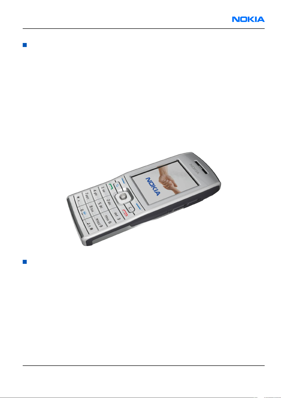
Figure 1 View of RM-170/171................................................................................................................................1–5
Issue 1 COMPANY CONFIDENTIAL Page 1 –3
Copyright © 2006 Nokia. All rights reserved.
Page 14

RM-170; RM-171
Nokia Customer Care General Information
(This page left intentionally blank.)
Page 1 –4 COMPANY CONFIDENTIAL Issue 1
Copyright © 2006 Nokia. All rights reserved.
Page 15
RM-170; RM-171
General Information Nokia Customer Care
Product selection
Nokia RM-170/171 is the first GSM quadband mobile phone in ES supporting 850/900/1800/1900 MHz bands.
RM-170/171 supports EGPRS packet data connection (EDGE) in all these bands. Supported multislot class for
both GPRS and EGPRS is MSC 10. RM-170/171 is based on G3.1S, RAP GSM engine.
According to GSM standard 05.05 it responds to class 4 (max. 2W) in EGSM 900, class 1 (1W) in GSM 1800 and
class 1 in GSM 1900. It also supports Bluetooth 1.2 standard. The handset has a full phase 2 Type Approval
and it complies with the GSM Type Approval. RM-170/171 also has a full CE approval and FCC approval.
RM-170 has a 1.3 megapixel camera with digital zoom up to 5x, there is no camera in RM-171.
Note: All subsequent references to camera concern RM-170 only.
Imaging is supported in familiar landscape camera mode with dedicated camera key. Display resolution is
320x240 and supports 262, 144 colours.
The MMS implementation follows the OMA MMS 1.2, AMR and SMIL.
WAP 2.0 compatible XHTML browser over HTTP/TCP/IP stack communicates with a gateway in network.
The supported UI is S60 release 3.0.
Figure 1 View of RM-170/171
Product features and sales package
Imaging
• Active QVGA colour display, 262,144 colours
• High Resolution 320x240 pixels, active area 33.48mm x 44.64mm
• 1.3MPix camera with integrated camera light
• Landscape mode for image capturing
• MicroSD card socket (hot swap)
Bearers & transport
• Quadband EGSM 900, GSM 850/1800/1900 supporting EDGE (rel. 99)
Software platform
• SW platform: Nokia Series 60
Issue 1 COMPANY CONFIDENTIAL Page 1 –5
Copyright © 2006 Nokia. All rights reserved.
Page 16
RM-170; RM-171
Nokia Customer Care General Information
Connectivity
• USB 2.0 full-speed
• Bluetooth 1.2
• Pop-Port™ connector with ACI
• IrDA (115 kbps)
Productivity
• SMS, MMS and email
• MS Word, PowerPoint , Excel and Adobe PDF viewers
• PIM (Calendar & Contacts)
• Internet browser
• Video streaming (3GPP)
• Push to Talk
• Logs (last calls , timers and history list)
• Audio messaging
•
JavaTM MIDP 2.0, CLDC 1.13D API, PIM API, File access API
• MP3
• Data Transfer
• Settings Wizard/Access Point Configurator
Sales package
• Transceiver RM-170/171
• BL-5C Li-Po Battery Cell
• AC Charger AC-4
• All-in-one User Guide (warranty card + accessory info + getting started sheet + invitational module for Club
Nokia )
• CD-ROM
• Mono Headset HS-5 (Hong Kong HS-23)
• USB Cable CA-53
• MicroSD card MU-26
• Add-on application guide
Product and module list
Module name Type code Notes
System/RF Module 1UT Main PWB with components.
Mobile enhancements
Table 1 Audio
Enhancement Type
Boom mono headset HDB-4
Page 1 –6 COMPANY CONFIDENTIAL Issue 1
Copyright © 2006 Nokia. All rights reserved.
Page 17
RM-170; RM-171
General Information Nokia Customer Care
Enhancement Type
Mono headset HS-5
Classic stereo headset HS-23
Loopset LPS-4
Wireless headset HDW-3
HS-4W
HS-11W
HS-58W
HS-25W
Wireless clip-on headset HS-21W
Wireless stereo headset HS-12W
Music stand MD-1
Table 2 Car
Enhancement Type
Nokia car kit phone N616
Headrest handsfree BHF-3
Basic handsfree HF-3
Advanced car kit (sales pack) (EURO 1) CK-7W
Car kit CK-10
Plug-in car handsfree HF-6W
Mobile holder CR-66
Table 3 Data
Enhancement Type
USB cable CA-53
(USB cable) (DKU-2)
PC suite
Table 4 Imaging
Enhancement Type
Nokia image album PD-1
Nokia remote camera PT-6
Issue 1 COMPANY CONFIDENTIAL Page 1 –7
Copyright © 2006 Nokia. All rights reserved.
Page 18
RM-170; RM-171
Nokia Customer Care General Information
Table 5 Messaging
Enhancement Type
Nokia digital pen (Eur/US) SU-1B
Nokia digital pen (Eur/US) SU-27W
Bluetooth QWERTY keypad (Scandinavian EURO 1) SU-8W
Table 6 Power
Enhancement Type
Compact charger AC-3
Battery Li-on BL-5C
Travel charger AC-4
Retractable charger AC-1
Charger adapter AC-44
Mobile charger DC-4
Technical specifications
Transceiver general specifications
Unit Dimensions (L x W x T) Weight (g)
Transceiver with BL-5C
battery
113 x 43.5 x 15.5 104 70
Volume (cm3)
Main RF characteristics for GSM850/900/1800/1900 (quadband) and EDGE phones
Parameter Unit
Cellular system GSM850, EGSM900, GSM1800/1900 and EDGE
Rx frequency band GSM850: 869 - 890 MHz
EGSM900: 925 - 960 MHz
GSM1800: 1805 - 1880 MHz
GSM1900: 1930 - 1990 MHz
Tx frequency band GSM850: 824 - 849 MHz
EGSM900: 880 - 915 MHz
GSM1800: 1710 - 1785 MHz
GSM1900: 1850 - 1910 MHz
Output power GSM850: +5 … +33dBm/3.2mW … 2W
GSM900: +5 … +33dBm/3.2mW … 2W
GSM1800: +0 … +30dBm/1.0mW … 1W
GSM1900: +0 … +30dBm/1.0mW … 1W
Page 1 –8 COMPANY CONFIDENTIAL Issue 1
Copyright © 2006 Nokia. All rights reserved.
Page 19
RM-170; RM-171
General Information Nokia Customer Care
Parameter Unit
EDGE output power EDGE850: +5 … +29dBm/3.2mW … 2W
EDGE900: +5 … +29dBm/3.2mW … 2W
EDGE1800: +0 … +26dBm/1.0mW … 1W
EDGE1900:+0 … +26dBm/1.0mW … 1W
Number of RF channels GSM850: 124
GSM900: 194
GSM1800: 374
GSM1900: 299
Channel spacing 200 kHz
Number of Tx power levels GSM850: 15
GSM900: 15
GSM1800: 16
GSM1900: 16
Number of EDGE Tx power levels GSM850 EDGE: 12
GSM900 EDGE: 12
GSM1800 EDGE: 14
GSM1900 EDGE: 14
Battery endurance
Battery Capacity (mAh) Talk time Stand-by
BL-5C 970mAh up to 6.8 hrs up to 200 hours
Charging times
AC-4
Up to 1 h 40 min
Environmental conditions
Environmental condition Ambient temperature Notes
Normal operation
Reduced performance
Intermittent operation
Issue 1 COMPANY CONFIDENTIAL Page 1 –9
-15oC...+55oC
-25oC...-15oC
+55oC...+70oC
-40oC...-25oC
+70oC...+85 oC
Copyright © 2006 Nokia. All rights reserved.
Specifications fulfilled
Operational for shorts periods
only
Operation not guaranteed but an
attempt to operate does not
damage the phone.
Page 20
RM-170; RM-171
Nokia Customer Care General Information
Environmental condition Ambient temperature Notes
No operation or storage
Charging allowed
Long term storage conditions
<-40oC...>+85oC
-25oC...+50oC
0oC...+85oC
No storage or operation: an
attempt may damage the phone.
Page 1 –10 COMPANY CONFIDENTIAL Issue 1
Copyright © 2006 Nokia. All rights reserved.
Page 21

Nokia Customer Care
2 — Parts Lists and Component
Layouts
Issue 1 COMPANY CONFIDENTIAL Page 2 –1
Copyright © 2006 Nokia. All rights reserved.
Page 22

RM-170; RM-171
Nokia Customer Care Parts Lists and Component Layouts
(This page left intentionally blank.)
Page 2 –2 COMPANY CONFIDENTIAL Issue 1
Copyright © 2006 Nokia. All rights reserved.
Page 23

RM-170; RM-171
Parts Lists and Component Layouts Nokia Customer Care
Table of Contents
Exploded view.........................................................................................................................................................2–5
Parts lists.................................................................................................................................................................2–6
Mechanical spare parts list...............................................................................................................................2–6
Component parts list.........................................................................................................................................2–7
Component layouts..............................................................................................................................................2–15
Component layout - bottom ..........................................................................................................................2–15
Component layout - top .................................................................................................................................2–16
Issue 1 COMPANY CONFIDENTIAL Page 2 –3
Copyright © 2006 Nokia. All rights reserved.
Page 24

RM-170; RM-171
Nokia Customer Care Parts Lists and Component Layouts
(This page left intentionally blank.)
Page 2 –4 COMPANY CONFIDENTIAL Issue 1
Copyright © 2006 Nokia. All rights reserved.
Page 25
RM-170; RM-171
Parts Lists and Component Layouts Nokia Customer Care
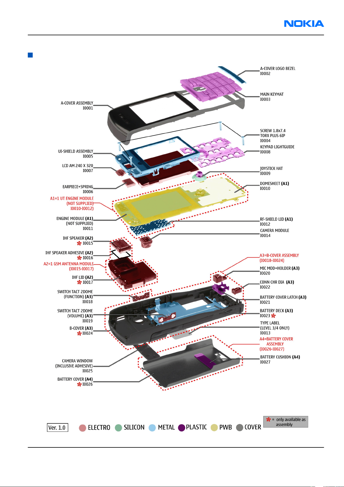
Exploded view
Issue 1 COMPANY CONFIDENTIAL Page 2 –5
Copyright © 2006 Nokia. All rights reserved.
Page 26
RM-170; RM-171
Nokia Customer Care Parts Lists and Component Layouts
Parts lists
Mechanical spare parts list
ITEM/ CIRCUIT REF. Part Name
I0001 A-COVER ASSEMBLY WHITE
I0002 A-COVER LOGO BEZEL
I0003 MAIN KEYMAT
I0004 SCREW 1.8x7.4 TORX PLUS 6IP
I0005 UI-SHIELD ASSEMBLY
I0006 EARPIECE+SPRING
I0007 LCD AM 240 X 320
I0008 KEYPAD LIGHTGUIDE
I0009 JOYSTICK HAT
A1 1 UT ENGINE MODULE (I0010 - I0012)
I0010 DOMESHEET
I0011 ENGINE MODULE
I0012 RF-SHIELD LID
I0013 TYPE LABEL
I0014 CAMERA MODULE ,RM-170 only
A2 1 GSM ANTENNA MODULE (I0015 - I0017)
I0015 IHF SPEAKER
I0016 IHF SPEAKER ADHESIVE
I0017 IHF LID
A3 B-COVER ASSEMBLY (I0018 - I0024)
I0018 SWITCH TACT 2DOME (FUNCTION)
I0019 SWITCH TACT 2DOME (VOLUME)
I0020 MIC MOD+HOLDER
I0021 BATTERY COVER LATCH
I0022 CONN CHR DIA
I0023 BATTERY DECK
I0024 B-COVER
I0025 CAMERA WINDOW ,RM-170
Camera Window blind ,RM-171
A4 BATTERY COVER ASSEMBLY (I0026 - I0027)
I0026 BATTERY COVER
Page 2 –6 COMPANY CONFIDENTIAL Issue 1
Copyright © 2006 Nokia. All rights reserved.
Page 27
RM-170; RM-171
Parts Lists and Component Layouts Nokia Customer Care
ITEM/ CIRCUIT REF. Part Name
I0027 BATTERY CUSHION
Component parts list
Component parts list 1ut_06a
Item Side Grid ref. Type Description and value
Resistor 5%
R7506 Bot B 17 0402R
R7507 Bot D 17 0402R
R7508 Bot B 16 0402R
R2030 Bot E 2 0402R
63mW 10R ~
Resistor 5%
63mW 10R ~
Resistor 5%
63mW 10R ~
Resistor 5%
63mW 100R ~
R2307 Bot D 15 0402R
R2101 Bot G 3 0402R
R2404 Top B 21 0402R
R2415 Bot E 22 0402R
R2440 Bot F 8 0402R
R2441 Bot F 8 0402R
R3213 Bot D 5 0402R
R7503 Bot B 17 0402R
R7509 Bot B 16 0402R
R2200 Bot E 11 0402R
Resistor 5%
63mW 100R ~
Resistor 5%
63mW 220R ~
Resistor 5%
63mW 220R ~
Resistor 5%
63mW 220R ~
Resistor 5%
63mW 220R ~
Resistor 5%
63mW 220R ~
Resistor 5%
63mW 2k2 ~
Resistor 5%
63mW 4k7 ~
Resistor 5%
63mW 22k ~
Resistor 5%
63mW 100k ~
Resistor 5%
R3214 Bot D 5 0402R
R7502 Bot D 18 0402R
R2008 Bot E 2 0404_RP
Issue 1 COMPANY CONFIDENTIAL Page 2 –7
Copyright © 2006 Nokia. All rights reserved.
63mW 100k ~
CHIPRES 0W06 10K
F 0402 10k ~
RES NETWORK
0W06 220K/120K J
0404
220k/
120k ~
Page 28
RM-170; RM-171
Nokia Customer Care Parts Lists and Component Layouts
Item Side Grid ref. Type Description and value
NTC RES 47K J
0402_NTH
R2071 Bot E 10
R2006 Bot E 2 0405_2
R2070 Bot F 16 0402_VAR
R2102 Top C 21 0402_VAR
R2103 Top C 21 0402_VAR
R2119 Bot D 19 0402_VAR
5
B=4050+-3%
0402 47k ~
VARISTOR ARRAY
2XVWM16V VC50
0405
CHIP VARISTOR
VWM14V VC50V
0402 14V/50V ~
CHIP VARISTOR
VWM14V VC50V
0402 14V/50V ~
CHIP VARISTOR
VWM14V VC50V
0402 14V/50V ~
CHIP VARISTOR
VWM14V VC50V
0402 14V/50V ~
2XVWM16
V ~
R2120 Bot D 20 0402_VAR
R2416 Bot F 22 0402_VAR
R2420 Bot A 17 0402_VAR
R2421 Bot A 17 0402_VAR
R2422 Bot A 17 0402_VAR
R2423 Bot H 17 0402_VAR
R2424 Bot H 17 0402_VAR
CHIP VARISTOR
VWM14V VC50V
0402 14V/50V ~
CHIP VARISTOR
VWM14V VC50V
0402 14V/50V ~
CHIP VARISTOR
VWM14V VC50V
0402 14V/50V ~
CHIP VARISTOR
VWM14V VC50V
0402 14V/50V ~
CHIP VARISTOR
VWM14V VC50V
0402 14V/50V ~
CHIP VARISTOR
VWM14V VC50V
0402 14V/50V ~
CHIP VARISTOR
VWM14V VC50V
0402 14V/50V ~
CHIP VARISTOR
VWM14V VC50V
R2425 Bot H 17 0402_VAR
Page 2 –8 COMPANY CONFIDENTIAL Issue 1
Copyright © 2006 Nokia. All rights reserved.
0402 14V/50V ~
Page 29
RM-170; RM-171
Parts Lists and Component Layouts Nokia Customer Care
Item Side Grid ref. Type Description and value
CHIP VARISTOR
VWM14V VC50V
R3210 Bot D 4 0402_VAR
C2102 Bot G 3 0603C
C2200 Bot G 11 0603C
C2306 Bot E 15 0603C
C3300 Bot G 16 0603C
C3301 Bot H 16 0603C
C7503 Bot B 17 0603C
0402 14V/50V ~
CHIPCAP X5R 2U2 K
6V3 0603 2u2 6V3
CHIPCAP X5R 1U K
6V3 0603 1u0 6.3V
CHIPCAP X5R 1U K
6V3 0603 1u0 6.3V
CHIPCAP X5R 4U7 K
6V3 0603 4u7 6.3V
CHIPCAP X5R 4U7 K
6V3 0603 4u7 6.3V
CHIPCAP X5R 4U7 K
6V3 0603 4u7 6.3V
CHIPCAP X5R 4U7 K
C7504 Bot D 17 0603C
C7506 Bot B 16 0603C
C7552 Bot D 22 0402C
C7501 Bot C 17 0402C
C7509 Bot B 17 0402C
C7520 Bot C 20 0402C
C6050 Bot H 6 0402C
C7553 Bot D 21 0402C Chipcap 5% NP0 10p 50V
C7554 Bot D 22 0402C Chipcap 5% NP0 10p 50V
C2404 Top C 21 0402C Chipcap 5% NP0 15p 50V
C2405 Top G 21 0402C Chipcap 5% NP0 15p 50V
6V3 0603 4u7 6.3V
CHIPCAP X5R 4U7 K
6V3 0603 4u7 6.3V
Chipcap +-0.25pF
NP0 1p0 50V
Chipcap +-0.25pF
NP0 2p7 50V
Chipcap +-0.25pF
NP0 2p7 50V
Chipcap +-0.25pF
NP0 3p3 50V
Chipcap +-0.25pF
NP0 6p8 50V
C2250 Top B 21 0402C Chipcap 5% NP0 22p 50V
C2415 Bot E 22 0402C Chipcap 5% NP0 22p 50V
C2000 Bot D 2 0402C Chipcap 5% NP0 27p 50V
C3100 Bot F 8 0402C Chipcap 5% NP0 27p 50V
C2402 Top F 21 0402C Chipcap 5% NP0 56p 50V
C7550 Bot D 22 0402C Chipcap 5% NP0 56p 50V
C7551 Bot D 22 0402C Chipcap 5% NP0 56p 50V
Issue 1 COMPANY CONFIDENTIAL Page 2 –9
Copyright © 2006 Nokia. All rights reserved.
Page 30
RM-170; RM-171
Nokia Customer Care Parts Lists and Component Layouts
Item Side Grid ref. Type Description and value
C2030 Bot E 2 0402C Chipcap 5% X7R 270p 50V
C7513 Bot B 16 0402C Chipcap 5% X7R 820p 50V
C7508 Bot B 17 0402C Chipcap 5% NP0 18p 50V
Chipcap X7R 10%
C2202 Bot E 10 0402C
C2205 Bot G 10 0402C
C2206 Bot F 10 0402C
C3314 Bot H 15 0402C
C7507 Bot B 16 0402C
C3313 Bot H 15 0402C
50V 0402 1n0 50V
Chipcap X7R 10%
50V 0402 1n0 50V
Chipcap X7R 10%
50V 0402 1n0 50V
Chipcap X7R 10%
16V 0402 10n 16V
Chipcap X7R 10%
16V 0402 10n 16V
CHIPCAP X5R 1U K
6V3 0402 1u0 6.3V
C3315 Bot H 16 0402C
0402C_H0.6CHIPCAP X5R 100N
C2400 Top F 21
0402C_H0.6CHIPCAP X5R 100N
C2401 Top F 22
0402C_H0.6CHIPCAP X5R 100N
C2700 Bot F 3
0402C_H0.6CHIPCAP X5R 100N
C3210 Bot D 5
0402C_H0.6CHIPCAP X5R 100N
C3311 Bot G 16
0402C_H0.6CHIPCAP X5R 100N
C3312 Bot H 17
0402C_H0.6CHIPCAP X5R 100N
C7518 Bot B 17
C7505 Bot B 16 0402C
C7530 Bot B 16 0402C
CHIPCAP X5R 1U K
6V3 0402 1u0 6.3V
M 16V 0402 100n 16V
M 16V 0402 100n 16V
M 16V 0402 100n 16V
M 16V 0402 100n 16V
M 16V 0402 100n 16V
M 16V 0402 100n 16V
M 16V 0402 100n 16V
CHIPCAP X5R 1U5 K
4V 0402 1u5 4V
CHIPCAP X5R 1U5 K
4V 0402 1u5 4V
0603C_H0
C2001 Bot C 2
C2070 Bot E 15
Page 2 –10 COMPANY CONFIDENTIAL Issue 1
Copyright © 2006 Nokia. All rights reserved.
.95
TANT_C_6.
2X3.4_H1.7CHIPTCAP 150U M
CHIPCAP X5R 470N
K 25V 0603 470n 25V
10V 6X3.2X1.5 150u_10V 10V
Page 31

RM-170; RM-171
Parts Lists and Component Layouts Nokia Customer Care
Item Side Grid ref. Type Description and value
FERRITE BEAD 0.6R
L2004 Bot E 2
L2005 Bot D 2
L2006 Bot D 2
L2401 Top F 22
L3300 Bot G 16
L3302 Bot D 16
FERRITE_0
402
FERRITE_0
402
FERRITE_0
402
FERRITE_0
402
FERRITE_0
402
FERRITE_0
402
600R/100MHZ
0402
FERRITE BEAD 0.6R
600R/100MHZ
0402
FERRITE BEAD 0.6R
600R/100MHZ
0402
FERRITE BEAD 0.6R
600R/100MHZ
0402
FERRITE BEAD 0.6R
600R/100MHZ
0402
FERRITE BEAD 0.6R
600R/100MHZ
0402
600R/
100MHz ~
600R/
100MHz ~
600R/
100MHz ~
600R/
100MHz ~
600R/
100MHz ~
600R/
100MHz ~
FERRITE_0
L7502 Bot B 17
L2000 Bot D 2 0603_BLM
Z7520 Bot D 20
L2001 Bot E 2
L2002 Bot F 2
L2003 Bot F 2
L2100 Top B 21
L7504 Bot C 18 0402L
402
FERRITE_F
BMJ1608
0405_2_M
ATSU
0405_2_M
ATSU
0405_2_M
ATSU
0405_2_M
ATSU
FERRITE BEAD 0.6R
600R/100MHZ
0402
FERR.BEAD 220R/
100M 2A 0R05
0603
FERRITE BEAD
0R01 28R/100MHZ
0603
CHIP BEAD ARRAY
2X1000R 0405
CHIP BEAD ARRAY
2X1000R 0405
CHIP BEAD ARRAY
2X1000R 0405
CHIP BEAD ARRAY
2X1000R 0405
CHIP COIL 22N J
Q28/800M 0402 22nH ~
600R/
100MHz ~
220R/
100MHz ~
28R/
100MHz ~
2x1000R/
100MHz ~
2x1000R/
100MHz ~
2x1000R/
100MHz ~
2x1000R/
100MHz ~
CHIP COIL 22N J
L7505 Bot C 19 0402L
L7500 Bot C 18 0402L
L7501 Bot C 19 0402L
Issue 1 COMPANY CONFIDENTIAL Page 2 –11
Copyright © 2006 Nokia. All rights reserved.
Q28/800M 0402 22nH ~
CHIP COIL 12N J
Q31/800M 0402 12nH ~
CHIP COIL 12N J
Q31/800M 0402 12nH ~
Page 32

RM-170; RM-171
Nokia Customer Care Parts Lists and Component Layouts
Item Side Grid ref. Type Description and value
CHIP COIL 4N7
0402L_H0
L7550 Bot D 22
L2102 Bot D 19 0402CS
V2302 Bot D 15 SOD323F
R2700 Bot G 8
V2000 Bot D 2
Z2002 Bot F 2 BGA11
.45
uBGA8_1.
47X1.47
BGA4_1.0
1X1.07 ASIP TVS BGA4 ~ ~
+-0N1 Q29/1GHZ
0402 4n7H ~
CHIP COIL WW 33N
J Q25/250MHZ
260MA 0402 33nH ~
SCH DI 30V 2A
SOD323F ~ ~
ASIP SIM
INTERFACE **LOW
CAP**BGA8 ~ ~
ASIP 4 LINES
AUDIO FILTER
BGA11 ~ ~
R2007 Bot E 2
R2100 Bot F 3
Z2401 Top F 21
Z2402 Top E 21
Z2403 Top E 21
Z2405 Top E 21
Z2406 Top E 21
Z2407 Top E 22
Z2409 Top C 9
uBGA11_1
.6X2.15
FLIP_CHIP
_8_1.7X1.
7
FC6_1.27X
0.86_P0.4
FC6_1.27X
0.86_P0.4
FC6_1.27X
0.86_P0.4
FC6_1.27X
0.86_P0.4
FC6_1.27X
0.86_P0.4
FC6_1.27X
0.86_P0.4
FC6_1.27X
0.86_P0.4
ASIP SILIC USB
OTG / ESD BGA11 ~ ~
ASIP SINGLE
ENDED
MICROPHONE
INTERF BGA8 ~ ~
ASIP 2-LINES EMI/
ESD FILTER BGA6 ~ ~
ASIP 2-LINES EMI/
ESD FILTER BGA6 ~ ~
ASIP 2-LINES EMI/
ESD FILTER BGA6 ~ ~
ASIP 2-LINES EMI/
ESD FILTER BGA6 ~ ~
ASIP 2-LINES EMI/
ESD FILTER BGA6 ~ ~
ASIP 2-LINES EMI/
ESD FILTER BGA6 ~ ~
ASIP 2-LINES EMI/
ESD FILTER BGA6 ~ ~
TRX2+RX4 PEMD9
N & P10K/47K
N2440 Bot E 8 SOT_666
USMD5_1.
47X1.04_
N3301 Bot H 15
Page 2 –12 COMPANY CONFIDENTIAL Issue 1
Copyright © 2006 Nokia. All rights reserved.
H0.675
0W12 SOT666 ~ ~
VREG
LP3985ITLX-2.8
NOPB USMD5 ~ 3V
Page 33

RM-170; RM-171
Parts Lists and Component Layouts Nokia Customer Care
Item Side Grid ref. Type Description and value
SC70_6_F
N7550 Bot D 22
N7520 Bot B 20
N7505 Bot C 18 TFBGA144
Z7501 Bot C 19
Z7521 Bot D 20
G2200 Top B 21
AIR
RF9282E3
.6
FILTER_2.
1X1.7_10
P_H0.6
FILTER_LF
TC10N
BATTER_E
ECEP
HIGH POWER SPDT
RF SW SC70 ~ ~
PW AMP
RF9282E6.3 VDET
SCREENED
VERSION ~ ~
RFIC AHNE400A
TRANSCEIVER
TFBGA144 ~ ~
DUAL RX SAW
FILTER
1800/1900MHZ
2016
CER FILT
LFL181699TC1
2400-2483MHZ
1.6
RTC BACUP CAPAC
311 SIZE FOR 2.6V
4UAH 2.6V ~
1800/190
0MHz ~
2400-248
3MHz ~
V2410 Top F 1
V2411 Top C 1
V2440 Top E 9
V2441 Top E 7
F2000 Bot D 2
S2425 Bot F 22
S2412 Top E 8
LED WHITE
LED_CL27
0
LED_CL27
0
LED_SML_
510
LED_SML_
510
0402_FUS
E_AVX_H0.5SM FUSE FF 2A 32V
SWITCH_E
VQP7A01KSM SW TACT SPST
SKRHAAE010SM SW 5WAY
100MCD 20MA
0DEG ~ ~
LED WHITE
100MCD 20MA
0DEG ~ ~
LED
SML-512MWT86
MIN 14MCD ~ ~
LED
SML-512MWT86
MIN 14MCD ~ ~
0402 2.0A ~
12V SIDE KEY 2.2N ~ ~
NAVIGATION KEY ~ ~
SOCKET_3
D114111
6_NS12_7
X3300 Bot G 17
Issue 1 COMPANY CONFIDENTIAL Page 2 –13
Copyright © 2006 Nokia. All rights reserved.
F
SOCKET COMPACT
ON-BOARD FOR
SMIA85 ~ ~
Page 34

RM-170; RM-171
Nokia Customer Care Parts Lists and Component Layouts
Item Side Grid ref. Type Description and value
LYNX_BAT
X2070 Bot F 15
X2000 Bot E 1
X2400 Top F 21
T_CONN_H
7.0
SYSCON_M
Q202_NK_
14R3
JST_R_JAV
K_G_1_R3
SM BATTERY CONN
3POL SPR 12V 2A ~ ~
SM SYSTEM
CONNECTOR 14POL ~ ~
SM CONN 2X12F
P0.4 30V .3A PWB/
PWB ~ ~
X2701 Bot F 6
X3200 Bot B 5
X2002 Bot B 1
M2100 Bot C 3
SIM_CONN
_P04_100
157_001
MOLEX_RS
D_501885
CON_JACK_
HR33NK_2
DJA_2S
VIBRA_M_
KHN4NX1
RA
SM SIM CONN
2X3POL P2.54 50V
0.5A ~ ~
CONN SMC
TRANSFLASH MMC ~ ~
CONN DC-JACK
2.0MM 3POL SPR
90DEG ~ ~
SMD VIBRA MOTOR
1.3V 80MA
9000RPM ~ ~
Page 2 –14 COMPANY CONFIDENTIAL Issue 1
Copyright © 2006 Nokia. All rights reserved.
Page 35

RM-170; RM-171
Parts Lists and Component Layouts Nokia Customer Care
Component layouts
Component layout - bottom
Issue 1 COMPANY CONFIDENTIAL Page 2 –15
Copyright © 2006 Nokia. All rights reserved.
Page 36

RM-170; RM-171
Nokia Customer Care Parts Lists and Component Layouts
Component layout - top
Page 2 –16 COMPANY CONFIDENTIAL Issue 1
Copyright © 2006 Nokia. All rights reserved.
Page 37

Nokia Customer Care
3 — Service Software
Instructions
Issue 1 COMPANY CONFIDENTIAL Page 3 –1
Copyright © 2006 Nokia. All rights reserved.
Page 38

RM-170; RM-171
Nokia Customer Care Service Software Instructions
(This page left intentionally blank.)
Page 3 –2 COMPANY CONFIDENTIAL Issue 1
Copyright © 2006 Nokia. All rights reserved.
Page 39

RM-170; RM-171
Service Software Instructions Nokia Customer Care
Table of Contents
Phoenix installation steps in brief........................................................................................................................3–5
Installing Phoenix...................................................................................................................................................3–6
Updating Phoenix installation..............................................................................................................................3–8
Uninstalling Phoenix..............................................................................................................................................3–9
Repairing Phoenix installation...........................................................................................................................3–11
Phone data package overview............................................................................................................................3–11
Installing phone data package...........................................................................................................................3–12
Uninstalling phone data package.......................................................................................................................3–15
Configuring users in Phoenix..............................................................................................................................3–17
Managing connections in Phoenix......................................................................................................................3–17
Installing flash support files for FPS-8 and FPS-10...........................................................................................3–19
Updating FPS-8 and FPS-10 flash prommer software.......................................................................................3–22
Activating FPS-8....................................................................................................................................................3–23
Deactivating FPS-8................................................................................................................................................3–24
List of Figures
Figure 2 Dongle not found.....................................................................................................................................3–6
Figure 3 Disclaimer text.........................................................................................................................................3–7
Figure 4 InstallShield Wizard Complete...............................................................................................................3–8
Figure 5 Installation interrupted..........................................................................................................................3–9
Figure 6 Remove program...................................................................................................................................3–10
Figure 7 Finish uninstallation.............................................................................................................................3–10
Figure 8 Repair program.....................................................................................................................................3–11
Figure 9 Data package setup information.........................................................................................................3–13
Figure 10 Data package destination folder.......................................................................................................3–14
Figure 11 InstallShield Wizard Complete...........................................................................................................3–15
Figure 12 Uninstalling phone data package......................................................................................................3–16
Figure 13 Finishing data package uninstallation..............................................................................................3–16
Figure 14 Phoenix login.......................................................................................................................................3–17
Figure 15 New user configured..........................................................................................................................3–17
Figure 16 Select mode: Manual...........................................................................................................................3–18
Figure 17 Connections list...................................................................................................................................3–19
Figure 18 Connection information.....................................................................................................................3–19
Figure 19 Product support module information (example from RM-1)..........................................................3–19
Figure 20 Flash update welcome dialog............................................................................................................3–20
Figure 21 Flash installation interrupted............................................................................................................3–20
Figure 22 Flash destination folder......................................................................................................................3–21
Figure 23 Finish flash update..............................................................................................................................3–22
Figure 24 Flash directory window......................................................................................................................3–22
Figure 25 Prommer software update finished..................................................................................................3–23
Figure 26 Prommer Maintenance window........................................................................................................3–23
Figure 27 Box activation......................................................................................................................................3–24
Figure 28 Deactivation warning.........................................................................................................................3–24
Issue 1 COMPANY CONFIDENTIAL Page 3 –3
Copyright © 2006 Nokia. All rights reserved.
Page 40

RM-170; RM-171
Nokia Customer Care Service Software Instructions
(This page left intentionally blank.)
Page 3 –4 COMPANY CONFIDENTIAL Issue 1
Copyright © 2006 Nokia. All rights reserved.
Page 41

RM-170; RM-171
Service Software Instructions Nokia Customer Care
Phoenix
installation steps in brief
Prerequisites
Recommended hardware requirements:
• Computer processor: Pentium 700 MHz or higher
• RAM 256 MB
• Disk space 100-300 MB
Supported operating systems:
•
Windows 2000
•
Windows XP
Service Pack 3 or higher
Service Pack 1 or higher
Context
Phoenix
is a service software for reprogramming, testing and tuning phones.
Phoenix
• Service software support for all phone models included in the package
• Flash update package files for programming devices
• All needed drivers for:
The phone model specific data package includes all changing product specific data:
• Product software binary files
• Files for type label printing
• Validation file for the faultlog repair data reporting system
• All product specific configuration files for
To use
installation contains:
• PKD-1 (DK2) dongle
• DKU-2 USB cable
Note: Separate installation packages for flash update files and drivers are also available, but it is
not necessary to use them unless there are updates between
separate update packages are used, they should be used after
installed.
Note:
Uninstallation should be made from the
Phoenix
Phoenix
, you need to:
and phone data packages should only be used as complete installation packages.
Phoenix
software components
Windows
Control Panel.
Phoenix
Phoenix
service software releases. If
and data packages have been
Steps
1. Connect a PKD-1 (DK2) dongle to the computer parallel port.
2. Install
3. Install the phone-specific data package.
4. Configure users.
5. Manage connection settings (depends on the tools you are using).
Issue 1 COMPANY CONFIDENTIAL Page 3 –5
Phoenix
If you use FPS-8: • Update FPS-8 software
.
• Activate FPS-8
Copyright © 2006 Nokia. All rights reserved.
Page 42

RM-170; RM-171
Nokia Customer Care Service Software Instructions
If you use FPS-10: • Update FPS-10 software
Note: There is no need to activate FPS-10.
• Activate SX-4 smart card, if you need tuning and
testing functions.
Note: When FPS-10 is used only for
product software updates, SX-4 smart
card is not needed.
Results
Phoenix
is ready to be used with FPS-8 or FPS-10 flash prommers and other service tools.
Installing
Phoenix
Prerequisites
• Check that a dongle is attached to the parallel port of your computer.
• Download the
computer (in
• Close all other programs.
• Depending on your operating system, administrator rights may be required to install
• If uninstalling or rebooting is needed at any point, you will be prompted by the InstallShield program.
Phoenix
C:\TEMP
installation package (for example,
, for instance).
phoenix_service_sw_2004_39_x_xx.exe
Phoenix
) to your
.
Context
At some point during the installation procedure, you may get the following message:
Figure 2 Dongle not found
This may be a result of a defective or too old PKD-1 dongle.
Check the COM/parallel ports used. After correcting the problem, you can restart the installation.
For more detailed information, please refer to
Tip: Each feature in
program. Press the F1 key or the feature’s Help button to activate a Help file.
Phoenix
has its own Help function, which can be activated while running the
Phoenix
Help files.
Steps
1. To start the installation, run the application file (for example,
2. In the
Page 3 –6 COMPANY CONFIDENTIAL Issue 1
Welcome
dialogue, click Next.
Copyright © 2006 Nokia. All rights reserved.
phoenix_service_sw_2004_39_x_xx.exe
).
Page 43

RM-170; RM-171
Service Software Instructions Nokia Customer Care
3. Read the disclaimer text carefully and click Yes.
Figure 3 Disclaimer text
4. Choose the destination folder.
The default folder
C:\ProgramFiles\Nokia\Phoenix
is recommended.
5. To continue, click Next.
To choose another location, click Browse (not recommended).
6. Wait for the components to be copied.
The progress of the installation is shown in the
Setup Status
window.
7. Wait for the drivers to be installed and updated.
The process may take several minutes to complete.
If the operating system does not require rebooting, the PC components are registered right away.
If the operating system requires restarting your computer, the Install Shield Wizard will notifies about it.
Select Yes... to reboot the PC immediately or No... to reboot the PC manually afterwards.
After the reboot, all components are registered.
Note:
Phoenix
does not work, if the components have not been registered.
Issue 1 COMPANY CONFIDENTIAL Page 3 –7
Copyright © 2006 Nokia. All rights reserved.
Page 44

RM-170; RM-171
Nokia Customer Care Service Software Instructions
8. To end the installation, click Finish.
Figure 4 InstallShield Wizard Complete
Next actions
After the installation,
• installing phone model specific data package for
• configuring users and connections
FPS-8 and FPS-10 flash prommers can be used after updating their flash update package files.
Updating
Phoenix
Phoenix
can be used after:
Phoenix
installation
Context
• If you already have the
software when new versions are released.
• To update
• When you are updating, for example, from version a14_2004_16_4_47 to a15_2004_24_7_55, the update
will take place automatically without uninstallation.
• Always use the latest available versions of both
can be found in the phone model specific Technical Bulletins and phone data package
(shown during installation).
• If you try to update
to a15_2004_24_7_55), you are asked if you want to uninstall the existing version. In this case you can
choose between a total uninstallation or a repair installation in a similar way when choosing to uninstall
the application from the
Phoenix
Phoenix
, you need to follow the same steps as when installing it for the first time.
Phoenix
Windows
service software installed on your computer, you need to update the
Phoenix
with the same version you already have (for example, a15_2004_24_7_55
Control Panel.
and the phone-specific data package. Instructions
readme.txt
files
• If you try to install an older version (for example, downgrade from a15_2004_24_7_55 to
a14_2004_16_4_47), installation will be interrupted.
Page 3 –8 COMPANY CONFIDENTIAL Issue 1
Copyright © 2006 Nokia. All rights reserved.
Page 45

RM-170; RM-171
Service Software Instructions Nokia Customer Care
Figure 5 Installation interrupted
• Always follow the instructions on the screen.
Steps
1. Download the installation package to your computer hard disk.
2. Close all other programs.
3. Run the application file (for example,
phoenix_service_sw_2004_39_x_xx.exe
).
Results
A new
Phoenix
version is installed and driver versions are checked and updated.
Uninstalling
Phoenix
Context
You can uninstall
Phoenix
service software manually from the
Windows
Control Panel.
Steps
1. Open the Windows Control Panel, and choose Add/Remove Programs.
Issue 1 COMPANY CONFIDENTIAL Page 3 –9
Copyright © 2006 Nokia. All rights reserved.
Page 46

RM-170; RM-171
Nokia Customer Care Service Software Instructions
2. To uninstall
Phoenix
, choose Phoenix Service Software→Change/Remove→Remove .
Figure 6 Remove program
The progress of the uninstallation is shown.
3. If the operating system does not require rebooting, click Finish to complete.
Figure 7 Finish uninstallation
Page 3 –10 COMPANY CONFIDENTIAL Issue 1
Copyright © 2006 Nokia. All rights reserved.
Page 47

RM-170; RM-171
Service Software Instructions Nokia Customer Care
If the operating system requires rebooting, InstallShield Wizard will notify you. Select Yes... to reboot the
PC immediately and No... to reboot the PC manually afterwards.
Repairing
Phoenix
installation
Context
If you experience any problems with the service software or suspect that files have been lost, use the repair
function before completely reinstalling
Note: The original installation package (for example,
must be found on your PC when you run the repair setup.
Phoenix
.
phoenix_service_sw_a15_2004_24_7_55.exe
Steps
1. Open Windows Control Panel→Add/Remove Programs .
2. Choose Phoenix Service Software→Change/Remove .
3. In the following view, select Repair.
)
Figure 8 Repair program
Phoenix
The procedure is the same as when updating
4. To complete the repair, click Finish.
reinstalls components and registers them.
Phoenix
.
Phone data package overview
Each product has its own data package (DP). The product data package contains all product-specific data files
to make the Phoenix service software and tools usable with a certain phone model.
The phone data package contains the following:
• Product software binary files
Issue 1 COMPANY CONFIDENTIAL Page 3 –11
Copyright © 2006 Nokia. All rights reserved.
Page 48

RM-170; RM-171
Nokia Customer Care Service Software Instructions
• Files for type label printing
• Validation file for the fault log repair data reporting system
• All product-specific configuration files for Phoenix software components
Data files are stored in C:\Program Files\Nokia\Phoenix (default).
Installing phone data package
Prerequisites
• A phone-specific data package contains all data required for the
to be used with a certain phone model.
• Check that a dongle is attached to the parallel port of your computer.
• Install
Phoenix
service software.
Phoenix
service software and service tools
• Download the installation package (for example,
in C:\TEMP).
• Close all other programs.
(XX-XX = type designator of the product)
If you already have
released.
Note: Often
version of
available versions of both. Instructions can be found in phone-specific Technical Bulletins and
readme.txt
Phoenix
Phoenix
Phoenix
files of data packages.
installed on your computer, you will need to update it when a new version is
and the phone-specific data package come in pairs, meaning that a certain
can only be used with a certain version of a data package. Always use the latest
XX-XX_dp_EA_v_1_0.exe
Steps
1. To start the installation, run the application file (for example,
Wait for the installation files to be extracted.
) to your computer (for example,
XX-XX_dp_EA_ v_1_0.exe
),
Page 3 –12 COMPANY CONFIDENTIAL Issue 1
Copyright © 2006 Nokia. All rights reserved.
Page 49

RM-170; RM-171
Service Software Instructions Nokia Customer Care
2. Click Next.
3. In the following view you can see the contents of the data package. Read the text carefully. There is
information about the
Phoenix
version required with this data package.
Figure 9 Data package setup information
4. To continue, click Next.
Issue 1 COMPANY CONFIDENTIAL Page 3 –13
Copyright © 2006 Nokia. All rights reserved.
Page 50

RM-170; RM-171
Nokia Customer Care Service Software Instructions
5. Choose the destination folder, and click Next to continue.
Figure 10 Data package destination folder
The InstallShield Wizard checks where
6. To start copying the files, click Next.
Phoenix
is installed, and the directory is shown.
Page 3 –14 COMPANY CONFIDENTIAL Issue 1
Copyright © 2006 Nokia. All rights reserved.
Page 51

RM-170; RM-171
Service Software Instructions Nokia Customer Care
Phone model specific files are installed. Please wait.
7. To complete the installation, click Finish.
Figure 11 InstallShield Wizard Complete
Next actions
Phoenix
• Configuring users
• Managing connections
FPS-8 and FPS-10 can be used after updating their flash update package files.
can be used for flashing phones and printing type labels after:
Uninstalling phone data package
Context
There is no need to uninstall an older version of a data package, unless instructions to do so are given in
the
readme.txt
Please read all related documents carefully.
file of the data package and bulletins related to the release.
Steps
1. Locate the data package installation file (e.g.
2. To start the uninstallation procedure, double-click the data package installation file.
XX-XX_dp_EA_v_1_0.exe
) from your computer.
Issue 1 COMPANY CONFIDENTIAL Page 3 –15
Copyright © 2006 Nokia. All rights reserved.
Page 52

RM-170; RM-171
Nokia Customer Care Service Software Instructions
3. To uninstall the data package, click OK or to interrupt the uninstallation, click Cancel.
Figure 12 Uninstalling phone data package
4. When the data package is uninstalled, click Finish.
Figure 13 Finishing data package uninstallation
Alternative steps
• You can also uninstall the data package manually from
Control Panel→Add/Remove Programs→xx-xx* Phone Data Package . (*= type designator of the
phone).
Page 3 –16 COMPANY CONFIDENTIAL Issue 1
Copyright © 2006 Nokia. All rights reserved.
Page 53

RM-170; RM-171
Service Software Instructions Nokia Customer Care
Configuring users in
Phoenix
Steps
1. Start
2. To add a new user, or to edit existing ones, click Maintain.
3. To add a new user, click New.
4. Type in the name and initials of the user, and click OK.
5. Select the desired user from the
Phoenix
If the user ID is already configured, select s/he from the
The user is added to the user name list.
service software, and log in.
Figure 14 Phoenix login
User name
drop-down list, and click OK.
User name
drop-down list, and click OK.
Figure 15 New user configured
Managing connections in
Phoenix
Context
With the Manage Connections feature you can edit and delete existing connections or create new ones.
Note: After choosing the desired connection, and connecting the phone to a PC for the first time,
allow the PC to install the USB device drivers first. Please note that this may take some time to
complete.
If there are problems after the driver installation, check that the USB connection is active from
the Windows Control Panel. If the problem persists, contact the local PC support.
Steps
1. Start
2. Choose File→Manage Connections... .
Issue 1 COMPANY CONFIDENTIAL Page 3 –17
Phoenix
, and log in.
Copyright © 2006 Nokia. All rights reserved.
Page 54

RM-170; RM-171
Nokia Customer Care Service Software Instructions
3. To add a new connection, click Add.
4. Select Manual mode, and click Next to continue.
If you want to create the connection using the Connection Wizard, connect the tools and a phone to your
PC. The wizard will automatically try to configure the correct connection.
Figure 16 Select mode: Manual
i For an FPS-10 flash prommer with a USB Connection, choose the following connection settings:
• Media: FPS-10 USB
• DEVICE_INDEX: 0
• SERIAL_NUM: See Serial No from the label attached to the bottom of FPS-10
• ACTIVE_MEDIA: USB
ii For an FPS-10 flash prommer with a LAN connection, choose the following connection settings:
• Media: FPS-10 TCP/IP
• NET_SERV_NAME: Click Scan.... Choose your own FPS-10 device based on the correct MAC address.
See Serial No from the label attached to the bottom of your FPS-10.
• PORT_NUM: Use the default value, and click Next.
• PROTOCOL_FAMILY: Use the default value, and click Next.
• SOCKET TYPE: Use the default value, and click Next.
• TX_BUFFER_SIZE: Use the default value, and click Next.
• RX_BUFFER_SIZE: Use the default value, and click Next.
iii For an FPS-8 flash prommer, choose the following connection settings:
• Media: FPS-8
• PORT_NUM: COM Port where FPS-8 is connected
• COMBOX_DEF_MEDIA: FBUS
Page 3 –18 COMPANY CONFIDENTIAL Issue 1
Copyright © 2006 Nokia. All rights reserved.
Page 55

RM-170; RM-171
Service Software Instructions Nokia Customer Care
iv For a plain USB connection, choose the following connection settings:
Note: First connect the DKU-2 USB cable between the PC USB port and phone.
• Media: USB
5. To complete the configuration, click Finish.
6. Click the connection you want to activate. Use the up/down arrows located on the right hand side to move
it on top of the list, then click Apply.
Figure 17 Connections list
The connection is activated, and it can be used after closing the
The connection information is shown at the right hand bottom corner of the screen.
Figure 18 Connection information
7. To use the connection, connect the phone to your PC with correct service tools. Make sure the phone is
switched on, and then choose File→Scan Product .
Manage Connection
window.
Results
The product support module information appears in the status bar:
Figure 19 Product support module information (example from RM-1)
Installing flash support files for FPS-8 and FPS-10
Prerequisites
• Install
• Install phone model specific data package for
• If you want to update the flash support files, they are delivered in the same installation package with
Phoenix
Phoenix
or newer
service software.
Phoenix
packages beginning from December 2004.
Phoenix
.
In case you want to update the MCU files, install the latest data package (see Technical Bulletins for
information on the latest one).
Normally, it is enough to install
always includes the latest flash update package files for FPS-8 and FPS-10.
• A separate installation package for flash support files is available. The files can be updated according to
these instructions, if updates appear between
Issue 1 COMPANY CONFIDENTIAL Page 3 –19
Phoenix
Copyright © 2006 Nokia. All rights reserved.
and the phone-specific data package because the installation
Phoenix
data package releases.
Page 56

RM-170; RM-171
Nokia Customer Care Service Software Instructions
Context
If you are not using a separate installation package, you can skip this section and continue with "Updating
FPS-8 and FPS-10 flash prommer software" (page 3–22) after installing a new phone data package.
Steps
1. To begin the installation, double-click the flash update file (for example,
flash_update_03_183_0014.exe
).
Figure 20 Flash update welcome dialog
If the same version of the flash update package already exists, and you want to reinstall it, the previous
package is first uninstalled.
Restart installation again after the uninstallation.
2. If you try to downgrade the existing version to older ones, the setup will be aborted. If there is a need to
downgrade the version, uninstall newer files manually from the Windows Control Panel, and then rerun
the installation.
Figure 21 Flash installation interrupted
If an older version exists on your PC and it needs to be updated, click Next to continue installation.
Page 3 –20 COMPANY CONFIDENTIAL Issue 1
Copyright © 2006 Nokia. All rights reserved.
Page 57

RM-170; RM-171
Service Software Instructions Nokia Customer Care
3. It is recommended to install the files to the default destination folder
To continue, click Next.
C:\Program Files\Nokia\Phoenix
.
Figure 22 Flash destination folder
When installing the flash update files for the first time, you may choose another location by selecting
Browse (not recommended).
Issue 1 COMPANY CONFIDENTIAL Page 3 –21
Copyright © 2006 Nokia. All rights reserved.
Page 58

RM-170; RM-171
Nokia Customer Care Service Software Instructions
4. To complete the installation procedure, click Finish .
Figure 23 Finish flash update
Next actions
FPS-8 and FPS-10 flash prommers must be updated using
Updating FPS-8 and FPS-10 flash prommer software
Phoenix
.
Steps
1. Start
2. Choose the correct connection for your flash prommer: File→Manage Connections...
3. Choose Flashing→Prommer maintenance .
4. To update the FPS-8/FPS-10 software, click Update, and select the appropriate file
Phoenix
or
fpsxupd.ini
service software, and log in.
(for FPS-10) from
C:\Program Files\Nokia\Phoenix\Flash
fps8upd.ini
.
(for FPS-8)
Figure 24 Flash directory window
Page 3 –22 COMPANY CONFIDENTIAL Issue 1
Copyright © 2006 Nokia. All rights reserved.
Page 59

RM-170; RM-171
Service Software Instructions Nokia Customer Care
Tip: All files can be loaded separately to the prommer used. To do this, click the right mouse button
in the
Flash Box Files
pane and select the file type(s) to be loaded.
5. Click OK.
Figure 25 Prommer software update finished
6. To close the
Prommer Maintenance
window, click Close.
Figure 26
Prommer Maintenance
window
Activating FPS-8
Context
Before FPS-8 can be successfully used for phone programming, it must first be activated.
First fill in the
When activation file is received (for example,
\BoxActivation
Issue 1 COMPANY CONFIDENTIAL Page 3 –23
FPS-8 activation request
sheet in the FPS-8 sales package, and follow the instructions given.
00000.in
), copy it to the
C:\ProgramFiles\Nokia\Phoenix
directory on your computer (this directory is created when
Copyright © 2006 Nokia. All rights reserved.
Phoenix
is installed).
Page 60

RM-170; RM-171
Nokia Customer Care Service Software Instructions
Steps
1. Start
2. Choose Flashing→Prommer Maintenance .
Phoenix
service software.
3. In the
4. To find the activation file, click Browse.
5. To activate the prommer, select the activation file and click Open.
6. To complete the activation, restart FPS-8.
Prommer Maintenance
window, click Activate.
Figure 27 Box activation
Deactivating FPS-8
Context
If there is, for example, a need to send the FPS-8 box for repair, it must be deactivated first.
Steps
1. Start
2. Choose Flashing→Prommer Maintenance .
3. In the
4. To confirm the deactivation, click Yes.
Phoenix
service software.
Prommer Maintenance
window, click Deactivate.
Figure 28 Deactivation warning
Page 3 –24 COMPANY CONFIDENTIAL Issue 1
Copyright © 2006 Nokia. All rights reserved.
Page 61

RM-170; RM-171
Service Software Instructions Nokia Customer Care
The box is deactivated.
5. To complete the deactivation, restart FPS-8.
Issue 1 COMPANY CONFIDENTIAL Page 3 –25
Copyright © 2006 Nokia. All rights reserved.
Page 62

RM-170; RM-171
Nokia Customer Care Service Software Instructions
(This page left intentionally blank.)
Page 3 –26 COMPANY CONFIDENTIAL Issue 1
Copyright © 2006 Nokia. All rights reserved.
Page 63

Nokia Customer Care
4 — Service Tools and Service
Concepts
Issue 1 COMPANY CONFIDENTIAL Page 4 –1
Copyright © 2006 Nokia. All rights reserved.
Page 64

RM-170; RM-171
Nokia Customer Care Service Tools and Service Concepts
(This page left intentionally blank.)
Page 4 –2 COMPANY CONFIDENTIAL Issue 1
Copyright © 2006 Nokia. All rights reserved.
Page 65

RM-170; RM-171
Service Tools and Service Concepts Nokia Customer Care
Table of Contents
Service tools............................................................................................................................................................4–5
CA-35S.................................................................................................................................................................4–5
CA-53...................................................................................................................................................................4–5
CU-4.....................................................................................................................................................................4–6
DKU-2..................................................................................................................................................................4–7
FLS-4S..................................................................................................................................................................4–7
FPS-10.................................................................................................................................................................4–8
FS-42...................................................................................................................................................................4–8
MJ-100.................................................................................................................................................................4–8
PCS-1...................................................................................................................................................................4–9
PKD-1..................................................................................................................................................................4–9
RJ-136.................................................................................................................................................................4–9
SA-119.................................................................................................................................................................4–9
SS-46...................................................................................................................................................................4–9
SS-62.................................................................................................................................................................4–10
XCS-4.................................................................................................................................................................4–10
XRF-1.................................................................................................................................................................4–10
Service concepts...................................................................................................................................................4–11
Flash concept with FPS-10..............................................................................................................................4–11
Flash concept with FPS-10 (USB)....................................................................................................................4–12
MJ-100 module jig concept............................................................................................................................4–13
POS (Point of Sale) flash concept...................................................................................................................4–14
Service concept for RF testing and RF/BB tuning.........................................................................................4–15
RF testing concept with RF coupler...............................................................................................................4–16
List of Figures
Figure 29 Basic flash concept with FPS-10.........................................................................................................4–11
Figure 30 Basic flash concept with FPS-10.........................................................................................................4–12
Figure 31 MJ-100 module jig service concept....................................................................................................4–13
Figure 32 POS flash concept................................................................................................................................4–14
Figure 33 Service concept for RF testing and RF/BB tuning.............................................................................4–15
Figure 34 RF testing concept with RF coupler...................................................................................................4–16
Issue 1 COMPANY CONFIDENTIAL Page 4 –3
Copyright © 2006 Nokia. All rights reserved.
Page 66

RM-170; RM-171
Nokia Customer Care Service Tools and Service Concepts
(This page left intentionally blank.)
Page 4 –4 COMPANY CONFIDENTIAL Issue 1
Copyright © 2006 Nokia. All rights reserved.
Page 67

RM-170; RM-171
Service Tools and Service Concepts Nokia Customer Care
Service tools
The table below gives a short overview of service tools that can be used for testing, error analysis and repair
of product RM-170; RM-171, refer to various concepts.
CA-35S Power cable CA-35S is a power cable for connecting, for example, the FPS-10 flash
prommer to the Point-Of-Sales (POS) flash adapter.
CA-53 USB connectivity
cable
USB to system connector cable.
Issue 1 COMPANY CONFIDENTIAL Page 4 –5
Copyright © 2006 Nokia. All rights reserved.
Page 68

RM-170; RM-171
Nokia Customer Care Service Tools and Service Concepts
CU-4 Control unit CU-4 is a general service tool used with a module jig and/or a flash
adapter. It requires an external 12 V power supply.
The unit has the following features:
• software controlled via USB
• EM calibration function
• Forwards FBUS/Flashbus traffic to/from terminal
• Forwards USB traffic to/from terminal
• software controlled BSI values
• regulated VBATT voltage
• 2 x USB2.0 connector (Hub)
• FBUS and USB connections supported
When using CU-4, note the special order of connecting cables and
other service equipment:
Instructions
1 Connect a service tool (jig, flash adapter) to CU-4.
2 Connect CU-4 to your PC with a USB cable.
3 Connect supply voltage (12 V)
4 Connect an FBUS cable (if necessary).
5 Start Phoenix service software.
Note: Phoenix enables CU-4 regulators via USB when it is
started.
Reconnecting the power supply requires a Phoenix restart.
Page 4 –6 COMPANY CONFIDENTIAL Issue 1
Copyright © 2006 Nokia. All rights reserved.
Page 69

RM-170; RM-171
Service Tools and Service Concepts Nokia Customer Care
DKU-2 USB connectivity
cable
USB to system connector cable.
FLS-4S Flash device FLS-4S is a dongle and flash device incorporated into one package,
developed specifically for POS use.
Issue 1 COMPANY CONFIDENTIAL Page 4 –7
Copyright © 2006 Nokia. All rights reserved.
Page 70

RM-170; RM-171
Nokia Customer Care Service Tools and Service Concepts
FPS-10 Flash prommer FPS-10 interfaces with:
• PC
• Control unit
• Flash adapter
• Smart card
FPS-10 flash prommer features:
• Flash functionality for BB5 and DCT-4 terminals
• Smart Card reader for SX-2 or SX-4
• USB traffic forwarding
• USB to FBUS/Flashbus conversion
• LAN to FBUS/Flashbus and USB conversion
• Vusb output switchable by PC command
FPS-10 sales package includes:
• FPS-10 prommer
• Power Supply with 5 country specific cords
• USB cable
FS-42 Flash adapter
Flash adapter FS-42 is used for phone testing and flashing. FS-42 is
used with the generic flash adapter base and control unit CU-4 or
interface adapter.
When flashing or system testing the phone, the adapter is attached to
replace the phone own battery. All functions (as well as the calibration
voltages, current and the protections for over voltages, over current
and voltage polarity), are performed by CU-4.
MJ-100 Module jig MJ-100 is meant for component level troubleshooting.
The jig includes an RF interface for GSM, WCDMA and Bluetooth. In
addition, it has the following features:
• Provides mechanical interface with Engine module
• Provides galvanic connection to all needed test pads in module
• Multiplexing between USB and FBUS media, controlled by Vusb
• UI test interface
• MMC interface
• Duplicated SIM connector
• Audio components: IHF, MIC, earpiece
• Connector for control unit
• Access for the system connector
Note: In the picture CU-4 is connected to MJ-100 . CU-4 is not
part of the MJ-100 sales package and has to be ordered
separately.
Page 4 –8 COMPANY CONFIDENTIAL Issue 1
Copyright © 2006 Nokia. All rights reserved.
Page 71

RM-170; RM-171
Service Tools and Service Concepts Nokia Customer Care
PCS-1 Power cable The PCS-1 power cable (DC) is used with a docking station, a module
jig or a control unit to supply a controlled operating voltage.
PKD-1 SW security device SW security device is a piece of hardware enabling the use of the
service software when connected to the parallel (LPT) port of the PC.
Without the device, it is not possible to use the service software.
Printer or any such device can be connected to the PC through the
device if needed.
RJ-136 Rework jig RJ-136 is a soldering jig used for soldering and as a rework jig for the
engine module.
SA-119 RF coupler SA-119 is a coupler for GSM RF testing. It is used together with FS-42
flash adapter.
SS-46 Interface adapter SS-46 acts as an interface adapter between the flash adapter and
FPS-10.
Issue 1 COMPANY CONFIDENTIAL Page 4 –9
Copyright © 2006 Nokia. All rights reserved.
Page 72

RM-170; RM-171
Nokia Customer Care Service Tools and Service Concepts
SS-62 Flash adapter base Generic base for flash adapters and couplers.
XCS-4 Modular cable XCS-4 is a shielded (one specially shielded conductor) modular cable
for flashing and service purposes.
XRF-1 RF cable The RF cable is used to connect, for example, a module repair jig to
the RF measurement equipment.
SMA to N-Connector ca. 610mm.
Attenuation for:
• GSM850/900: 0.3+-0.1 dB
• GSM1800/1900: 0.5+-0.1 dB
• WLAN: 0.6+-0.1dB
Page 4 –10 COMPANY CONFIDENTIAL Issue 1
Copyright © 2006 Nokia. All rights reserved.
Page 73

RM-170; RM-171
Service Tools and Service Concepts Nokia Customer Care
Service concepts
Flash concept with FPS-10
Figure 29 Basic flash concept with FPS-10
Description Type
FS-42 Flash adapter
SS-46 Interface adapter
CA-35S Power cable
XCS-4 Modular cable
FPS-10 Flash prommer box
CA-31D USB cable
PKD-1 SW security device
Issue 1 COMPANY CONFIDENTIAL Page 4 –11
Copyright © 2006 Nokia. All rights reserved.
Page 74

RM-170; RM-171
Nokia Customer Care Service Tools and Service Concepts
Flash concept with FPS-10 (USB)
Figure 30 Basic flash concept with FPS-10
Description Type
FS-42 Flash adapter
SS-62 Flash adapter base
CA-35S Power cable
CU-4 Control unit
FPS-10 Flash prommer box
CA-31D Standard USB cable
PKD-1 SW security device
Page 4 –12 COMPANY CONFIDENTIAL Issue 1
Copyright © 2006 Nokia. All rights reserved.
Page 75

RM-170; RM-171
Service Tools and Service Concepts Nokia Customer Care
MJ-100 module jig concept
Figure 31 MJ-100 module jig service concept
Type Description
MJ-100 Module jig
CU-4 Control unit
FPS-10 Flash prommer
SX-4 Smart card
XCS-4 Modular cable
PCS-1 DC power cable
CA-31D USB cable
GPIB control cable
XRS-6 RF cable
PKD-1 SW security device
Issue 1 COMPANY CONFIDENTIAL Page 4 –13
Copyright © 2006 Nokia. All rights reserved.
Page 76

RM-170; RM-171
Nokia Customer Care Service Tools and Service Concepts
POS (Point of Sale) flash concept
Figure 32 POS flash concept
Type Description
CA-53 Cable
FLS-4S POS flash dongle
Page 4 –14 COMPANY CONFIDENTIAL Issue 1
Copyright © 2006 Nokia. All rights reserved.
Page 77

RM-170; RM-171
Service Tools and Service Concepts Nokia Customer Care
Service concept for RF testing and RF/BB tuning
Figure 33 Service concept for RF testing and RF/BB tuning
Description Type
MJ-100 Module jig
CU-4 Control unit
CA-31D USB cable
PCS-1 DC power cable
Standard USB cable + smart card reader
SX-4 Smart card
XRS-6 RF cable
GPIB control cable
PKD-1 SW security device
Issue 1 COMPANY CONFIDENTIAL Page 4 –15
Copyright © 2006 Nokia. All rights reserved.
Page 78

RM-170; RM-171
Nokia Customer Care Service Tools and Service Concepts
RF testing concept with RF coupler
Figure 34 RF testing concept with RF coupler
Type Description
FS-42 Flash adapter
CU-4 Control unit
SA-119 RF coupler
PCS-1 Power cable
XCS-4 Cable
SS-62 Jig
CA-31D USB cable
SX-4 Smart card
GPIB control cable
XRS-6 RF cable
PKD-1 SW security device
Page 4 –16 COMPANY CONFIDENTIAL Issue 1
Copyright © 2006 Nokia. All rights reserved.
Page 79

Nokia Customer Care
5 — Disassembly/reassembly
instructions
Issue 1 COMPANY CONFIDENTIAL Page 5 –1
Copyright © 2006 Nokia. All rights reserved.
Page 80

RM-170; RM-171
Nokia Customer Care Disassembly/reassembly instructions
(This page left intentionally blank.)
Page 5 –2 COMPANY CONFIDENTIAL Issue 1
Copyright © 2006 Nokia. All rights reserved.
Page 81

RM-170; RM-171
Disassembly/reassembly instructions Nokia Customer Care
Table of Contents
Disassembly instructions.......................................................................................................................................5–5
Reassembly instructions......................................................................................................................................5–14
List of Figures
Figure 35 Needed tools: a bit holding screwdriver, a Torque screwdriver, a Torx PLUS size 6 bit, metal
tweezers, a DC plug, the SS-93 opening tool, the SS-102 camera removal tool and a dental pick.
.......................................................................................................................................................................5–5
Issue 1 COMPANY CONFIDENTIAL Page 5 –3
Copyright © 2006 Nokia. All rights reserved.
Page 82

RM-170; RM-171
Nokia Customer Care Disassembly/reassembly instructions
(This page left intentionally blank.)
Page 5 –4 COMPANY CONFIDENTIAL Issue 1
Copyright © 2006 Nokia. All rights reserved.
Page 83

RM-170; RM-171
Disassembly/reassembly instructions Nokia Customer Care
Disassembly instructions
Prerequisites
Figure 35 Needed tools: a bit holding screwdriver, a Torque screwdriver, a Torx PLUS size 6 bit, metal tweezers, a DC plug,
the SS-93 opening tool, the SS-102 camera removal tool and a dental pick.
Steps
1. Press the BATTERY COVER LATCH and lift a bit the BATTERY COVER ASSEMBLY.
Issue 1 COMPANY CONFIDENTIAL Page 5 –5
Copyright © 2006 Nokia. All rights reserved.
Page 84

RM-170; RM-171
Nokia Customer Care Disassembly/reassembly instructions
2. Now remove the BATTERY COVER ASSEMBLY.
3. Unlock the A-COVER with the SS-93 starting on the top side of the phone.
4. Slide the SS-93 along the edge to unlock the snaps.
Page 5 –6 COMPANY CONFIDENTIAL Issue 1
Copyright © 2006 Nokia. All rights reserved.
Page 85

RM-170; RM-171
Disassembly/reassembly instructions Nokia Customer Care
5. Do the same on the other side.
6. Separate the parts from each other.
7. Remove the KEYMAT from the A-COVER.
Issue 1 COMPANY CONFIDENTIAL Page 5 –7
Copyright © 2006 Nokia. All rights reserved.
Page 86

RM-170; RM-171
Nokia Customer Care Disassembly/reassembly instructions
8. Undo the screws in the order shown and remove them.
Note: For assembly: Use the same order and a torque of 20 Ncm for re-assembly.
9. Unlock the UI SHIELD ASSEMBLY with the SS-93.
10. Unlock the second snap of the UI SHIELD.
Page 5 –8 COMPANY CONFIDENTIAL Issue 1
Copyright © 2006 Nokia. All rights reserved.
Page 87

RM-170; RM-171
Disassembly/reassembly instructions Nokia Customer Care
11. Remove the ENGINE MODULE from the B-COVER.
12. Use the SS-93 to open the snaps of the UI SHIELD.
13. Now, remove the UI SHIELD.
Issue 1 COMPANY CONFIDENTIAL Page 5 –9
Copyright © 2006 Nokia. All rights reserved.
Page 88

RM-170; RM-171
Nokia Customer Care Disassembly/reassembly instructions
14. Remove the EARPIECE.
15. Carefully, open the LCD connector with the SS-93 paying attention to the surrounding components.
16. Remove the LCD.
Page 5 –10 COMPANY CONFIDENTIAL Issue 1
Copyright © 2006 Nokia. All rights reserved.
Page 89

RM-170; RM-171
Disassembly/reassembly instructions Nokia Customer Care
17. Use tweezers to remove the JOYSTICK HAT. Note the right position to JOYSTICK HAT when assembling the
unit.
18. Unlock and remove the CAMERA MODULE with the SS-102 camera removal tool.
19. Note the right position of the CAMERA MODULE when assembling the unit.
Issue 1 COMPANY CONFIDENTIAL Page 5 –11
Copyright © 2006 Nokia. All rights reserved.
Page 90

RM-170; RM-171
Nokia Customer Care Disassembly/reassembly instructions
20. Remove the 1GSM ANTENNA MODULE.
21. Gently, remove the VOLUME and FUNCTION switches using tweezers.
22. Remove the MICROPHONE avoiding bending the spring contacts.
Page 5 –12 COMPANY CONFIDENTIAL Issue 1
Copyright © 2006 Nokia. All rights reserved.
Page 91

RM-170; RM-171
Disassembly/reassembly instructions Nokia Customer Care
23. Use the DC-plug to unlock and remove the DC-JACK.
24. Remove the BATTERY COVER LATCH.
25. The disassembly procedure is now complete.
Issue 1 COMPANY CONFIDENTIAL Page 5 –13
Copyright © 2006 Nokia. All rights reserved.
Page 92

RM-170; RM-171
Nokia Customer Care Disassembly/reassembly instructions
Reassembly instructions
For reassembly, follow the disassembly instructions, but in reversed order, unless otherwise stated.
Page 5 –14 COMPANY CONFIDENTIAL Issue 1
Copyright © 2006 Nokia. All rights reserved.
Page 93

Nokia Customer Care
6 — BB Troubleshooting and
Manual Tuning Guide
Issue 1 COMPANY CONFIDENTIAL Page 6 –1
Copyright © 2006 Nokia. All rights reserved.
Page 94

RM-170; RM-171
Nokia Customer Care BB Troubleshooting and Manual Tuning Guide
(This page left intentionally blank.)
Page 6 –2 COMPANY CONFIDENTIAL Issue 1
Copyright © 2006 Nokia. All rights reserved.
Page 95

RM-170; RM-171
BB Troubleshooting and Manual Tuning Guide Nokia Customer Care
Table of Contents
Baseband troubleshooting....................................................................................................................................6–5
General power checking troubleshooting...........................................................................................................6–7
Clocking troubleshooting......................................................................................................................................6–8
Display module troubleshooting..........................................................................................................................6–9
General instructions for display troubleshooting..........................................................................................6–9
Display fault troubleshooting........................................................................................................................6–11
Display and keyboard backlight troubleshooting........................................................................................6–12
USB troubleshooting............................................................................................................................................6–14
Charging troubleshooting...................................................................................................................................6–15
Dead or jammed phone troubleshooting..........................................................................................................6–16
Vibra troubleshooting..........................................................................................................................................6–17
MicroSD troubleshooting.....................................................................................................................................6–18
Power key troubleshooting.................................................................................................................................6–19
SIM troubleshooting.............................................................................................................................................6–20
Irda troubleshooting............................................................................................................................................6–21
Keyboard troubleshooting..................................................................................................................................6–22
Battery current measuring fault troubleshooting............................................................................................6–24
Flash programming fault troubleshooting........................................................................................................6–25
Backup battery troubleshooting.........................................................................................................................6–25
Bluetooth troubleshooting..................................................................................................................................6–26
Introduction to Bluetooth troubleshooting.................................................................................................6–26
Bluetooth settings for Phoenix......................................................................................................................6–26
Bluetooth self tests in Phoenix......................................................................................................................6–27
Bluetooth BER failure troubleshooting.........................................................................................................6–29
BT audio failure troubleshooting..................................................................................................................6–30
Audio troubleshooting.........................................................................................................................................6–31
Audio troubleshooting test instructions......................................................................................................6–31
Internal earpiece troubleshooting................................................................................................................6–34
Internal microphone troubleshooting..........................................................................................................6–35
IHF troubleshooting........................................................................................................................................6–36
External microphone troubleshooting..........................................................................................................6–37
External earpiece troubleshooting................................................................................................................6–38
Introduction to acoustics troubleshooting..................................................................................................6–39
Acoustics earpiece troubleshooting..............................................................................................................6–40
Acoustics IHF troubleshooting.......................................................................................................................6–41
Acoustics microphone troubleshooting........................................................................................................6–42
Baseband manual tuning guide.........................................................................................................................6–43
Energy management calibration...................................................................................................................6–43
List of Tables
Table 7 Display module troubleshooting cases................................................................................................6–10
Table 8 Pixel defects............................................................................................................................................6–10
Table 9 Calibration value limits..........................................................................................................................6–43
List of Figures
Figure 36 SleepCLK..................................................................................................................................................6–9
Figure 37 SYSCLK.....................................................................................................................................................6–9
Figure 38 Flashing pic 1. Take single trig measurement for the rise of the BSI signal.................................6–25
Issue 1 COMPANY CONFIDENTIAL Page 6 –3
Copyright © 2006 Nokia. All rights reserved.
Page 96

RM-170; RM-171
Nokia Customer Care BB Troubleshooting and Manual Tuning Guide
Figure 39 Flashing pic 2. Take single trig measurement for the rise of the BSI signal.................................6–25
Figure 40 Charging backup battery....................................................................................................................6–26
Figure 41 Discharging backup battery...............................................................................................................6–26
Figure 42 BER test result......................................................................................................................................6–27
Figure 43 Bluetooth self tests in Phoenix..........................................................................................................6–28
Figure 44 Single-ended output waveform of the Ext_in_HP_out measurement when earpiece is
connected...................................................................................................................................................6–33
Figure 45 Differential output waveform of the Ext_in_IHF_out out loop measurement when speaker is
connected...................................................................................................................................................6–33
Figure 46 Single-ended output waveform of the HP_in_Ext_out loop when microphone is connected....
6–33
Page 6 –4 COMPANY CONFIDENTIAL Issue 1
Copyright © 2006 Nokia. All rights reserved.
Page 97

RM-170; RM-171
BB Troubleshooting and Manual Tuning Guide Nokia Customer Care
Baseband troubleshooting
Context
This section is intended to be a guide for localising and repairing electrical faults. The fault repairing is divided
into troubleshooting paths.
The following main troubleshooting tree describes the different baseband troubleshooting paths to be
followed in fault situations.
Issue 1 COMPANY CONFIDENTIAL Page 6 –5
Copyright © 2006 Nokia. All rights reserved.
Page 98

RM-170; RM-171
Nokia Customer Care BB Troubleshooting and Manual Tuning Guide
Troubleshooting flow
Page 6 –6 COMPANY CONFIDENTIAL Issue 1
Copyright © 2006 Nokia. All rights reserved.
Page 99

RM-170; RM-171
BB Troubleshooting and Manual Tuning Guide Nokia Customer Care
General power checking troubleshooting
Troubleshooting flow
Issue 1 COMPANY CONFIDENTIAL Page 6 –7
Copyright © 2006 Nokia. All rights reserved.
Page 100

RM-170; RM-171
Nokia Customer Care BB Troubleshooting and Manual Tuning Guide
Clocking troubleshooting
Troubleshooting flow
Page 6 –8 COMPANY CONFIDENTIAL Issue 1
Copyright © 2006 Nokia. All rights reserved.
 Loading...