

Page 1

DNT2Mi-fp
Data Network Terminal
User manual
C33999.21 B0
DN0445814 © Nokia Corporation 1 (60)
Issue 2-0 en Nokia Proprietary and Confidential
Page 2
DNT2Mi-fp Data Network Terminal User manual
The information in this documentation is subject to change without notice and describes only
the product defined in the introduction of this documentation. This documentation is intended
for the use of Nokia's customers only for the purposes of the agreement under which the
documentation is submitted, and no part of it may be reproduced or transmitted in any form or
means without the prior written permission of Nokia. The documentation has been prepared to
be used by professional and properly trained personnel, and the customer assumes full
responsibility when using it. Nokia welcomes customer comments as part of the process of
continuous development and improvement of the documentation.
The information or statements given in this documentation concerning the suitability, capacity,
or performance of the mentioned hardware or software products cannot be considered binding
but shall be defined in the agreement made between Nokia and the customer. However, Nokia
has made all reasonable efforts to ensure that the instructions contained in the documentation
are adequate and free of material errors and omissions. Nokia will, if necessary, explain issues
which may not be covered by the documentation.
Nokia's liability for any errors in the documentation is limited to the documentary correction of
errors. NOKIA WILL NOT BE RESPONSIBLE IN ANY EVENT FOR ERRORS IN THIS
DOCUMENTATION OR FOR ANY DAMAGES, INCIDENTAL OR CONSEQUENTIAL
(INCLUDING MONETARY LOSSES), that might arise from the use of this documentation or
the information in it.
This documentation and the product it describes are considered protected by copyright
according to the applicable laws.
NOKIA logo is a registered trademark of Nokia Corporation.
Other product names mentioned in this documentation may be trademarks of their respective
companies, and they are mentioned for identification purposes only.
Copyright © Nokia Corporation 2005. All rights reserved.
The following products comply with the protection requirements of the European Union Council
Directive 89/336/EEC relating to electromagnetic compatibility (EMC), provided that installed
using EMC-compatible installation practices (installation in mechanical housings stated to be
EMC-compatible and using cabling material [at least as well shielded] and practices as stated
in relevant Nokia user manuals):
Product code Product versions
T65690.01 DNT2Mi-fp 2w G.704
T65690.02 DNT2Mi-fp 4w G.704
2 (60) © Nokia Corporation DN0445814
Nokia Proprietary and Confidential Issue2-0en
Page 3

Contents
1 About this document 7
2 Introduction to DNT2Mi-fp 9
3 Front view 11
4 Rear panel 13
4.1 Line interface 14
4.2 Power supply 14
4.3 Terminal interface 21
5 Management 23
6 Commissioning 27
6.1 Management 28
6.2 Timing source 28
6.3 Line settings 29
6.4 Port settings 30
6.5 Protection settings 30
6.6 Measurements 31
Contents 3
Summary of changes 5
7 Maintenance 33
7.1 Getting general information 33
7.2 Monitoring alarms 34
7.3 Testing 35
7.4 Checking measurements and statistics 37
8 Technical specifications 39
9 Factory settings 45
Appendix A. Q1 menu diagrams 47
DN0445814 © Nokia Corporation 3 (60)
Issue 2-0 en Nokia Proprietary and Confidential
Page 4

DNT2Mi-fp Data Network Terminal User manual
4 (60) © Nokia Corporation DN0445814
Nokia Proprietary and Confidential Issue2-0en
Page 5
Summary of changes
Prod
Document Date Comment
DN0445814 issue 2–0 en Aug 2005
DN0445814 Issue 1–0 en Mar 2004
Product collection and disposal within the European Union
Guidelines for product collection and safe disposal of the equipment are indicated
with a sticker placed on the equipment, shown in the figure below.
uct collection and disposal within European Union
Do not dispose the
product as unsorted
municipal waste.
The crossed-out
wheeled bin means that
at the product end-of life
the product must be taken
to separate collection.
Note: this is applicable only
within European Union
(see WEEE Directive 2002/96/EC)
DN0577953
Figure 1. Product collection and disposal within the European Union
DN0445814 © Nokia Corporation 5 (60)
Issue 2-0 en Nokia Proprietary and Confidential
Page 6

DNT2Mi-fp Data Network Terminal User manual
6 (60) © Nokia Corporation DN0445814
Nokia Proprietary and Confidential Issue2-0en
Page 7

1 About this document
This manual introduces the DNT2Mi-fp network terminal and provides
information needed for its installation and use.
This manual is intended for those who use DNT2Mi-fp as a network terminal. If
you use it in a ACL2i-DNT2Mi-fp connection, refer to the ACL2i User Manual,
which contains descriptions of the ACL2i, its functions and Q1 menus.
About this document
DN0445814 © Nokia Corporation 7 (60)
Issue 2-0 en Nokia Proprietary and Confidential
Page 8

DNT2Mi-fp Data Network Terminal User manual
8 (60) © Nokia Corporation DN0445814
Nokia Proprietary and Confidential Issue2-0en
Page 9
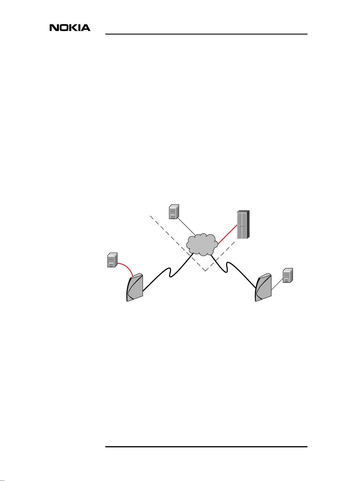
2 Introduction to DNT2Mi-fp
Nokia DNT2Mi-fp is a fixed port data access network terminal intended for
customer premises. It provides a two-wire or four-wire SHDSL line interface
(ITU-T G.991.2) and symmetrical 2M data interface (ITU-T G.704).
The DNT2Mi-fp Data Network Terminal can be used for example for BTS and
PABX (E1) connections (see Figure 2). DNT2Mi-fp can be controlled,
configured, and tested using Nokia’s common network management system
(NMS). It can also be controlled locally using MSTE or Craft Terminal running
on a PC or ST (hand held service terminal).
Introduction to DNT2Mi-fp
BSC
PDH
Network
PABX
SHDSL
DNT2Mi-fp
Figure 2. Example of DNT2Mi-fp connection
Local
Exchange
BTS
DNT2Mi-fp
DN0445814 © Nokia Corporation 9 (60)
Issue 2-0 en Nokia Proprietary and Confidential
Page 10
DNT2Mi-fp Data Network Terminal User manual
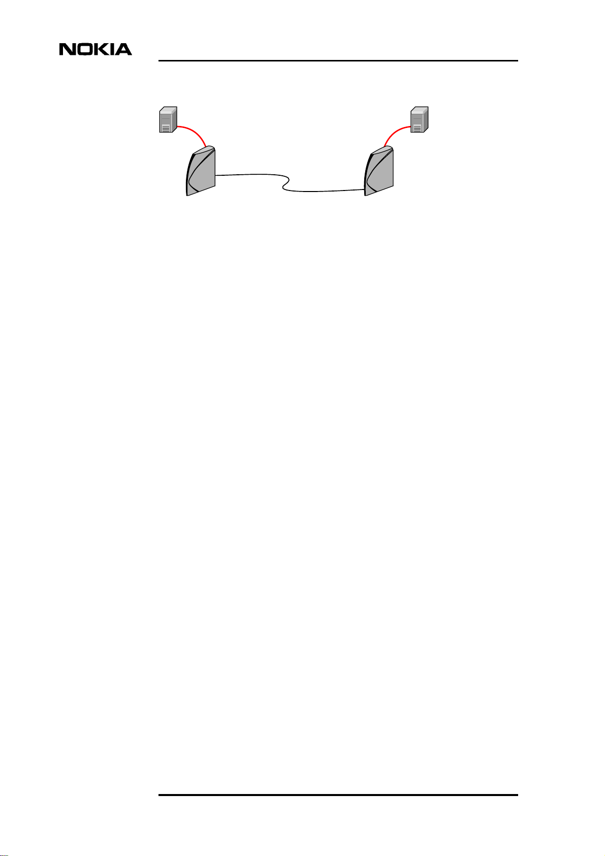
BTS
BTS
SHDSL
DNT2Mi-fpDNT2Mi-fp
Figure 3. DNT2Mi-fp used in a point-to-point application
DNT2Mi-fp can also be used in point-to-point connections with a DNT2Mi-fp
terminal at both ends of the line (see Figure 3)
10 (60) © Nokia Corporation DN0445814
Nokia Proprietary and Confidential Issue2-0en
Page 11
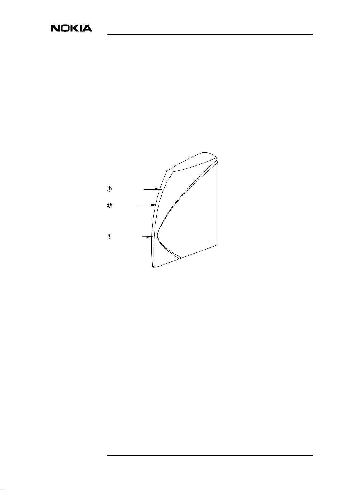
3 Front view
Figure 4 presents DNT2Mi-fp front view with LED indicators.
Power LED
Front view
DSL LED
Alarm LED
Figure 4. Front view of DNT2Mi-fp
When power is switched on, the unit performs an automatic self test, which is
used to check the most vital operational functions of the equipment. After the test,
the device is ready for use.
During the power-up test, the LEDs are lit in the following sequence:
1. All 3 LEDs are lit for 10 seconds.
2. The green power LED is blinking and others are off for 10 seconds during
startup and self test.
3. The green power LED is lit and DNT2Mi-fp is ready for use.
The green DSL LED indicates state of the line.
DN0445814 © Nokia Corporation 11 (60)
Issue 2-0 en Nokia Proprietary and Confidential
Page 12

DNT2Mi-fp Data Network Terminal User manual
• If there is no line signal, the DSL LED is off.
• If line is handshaking, the DSL LED is blinking.
• If the line is up and running, the DSL LED is lit.
The yellow Alarm LED indicates alarm situation.
• If there is no alarm situation, the LED is off.
• The Alarm LED is lit for instance if:
• no line signal or handshaking is ongoing or too high bit error ration
(BER).
• no E1 data signal or framing error or too high bit error ration (BER).
For more information see the Maintenance chapter.
12 (60) © Nokia Corporation DN0445814
Nokia Proprietary and Confidential Issue2-0en
Page 13
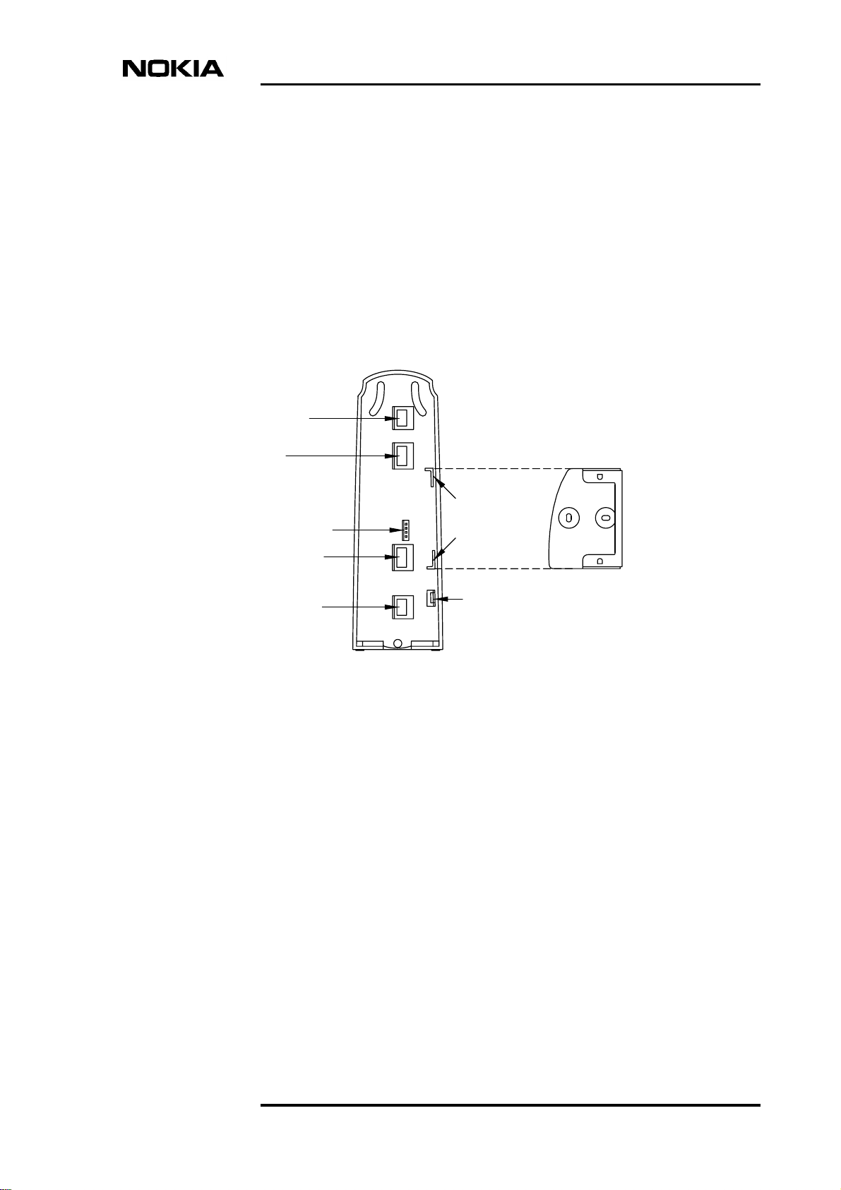
4 Rear panel
Figure 5 shows connector locations on the rear panel of a DNT2Mi-fp.
48VDC
Rear panel
LMI
Slots for wall
DIP Switch
G.704/2M
DSL Line
Figure 5. Rear panel connectors of the DNT2Mi-fp unit
mounting
fastener
Earthing
connector
Wall mounting
fastener
DN0445814 © Nokia Corporation 13 (60)
Issue 2-0 en Nokia Proprietary and Confidential
Page 14
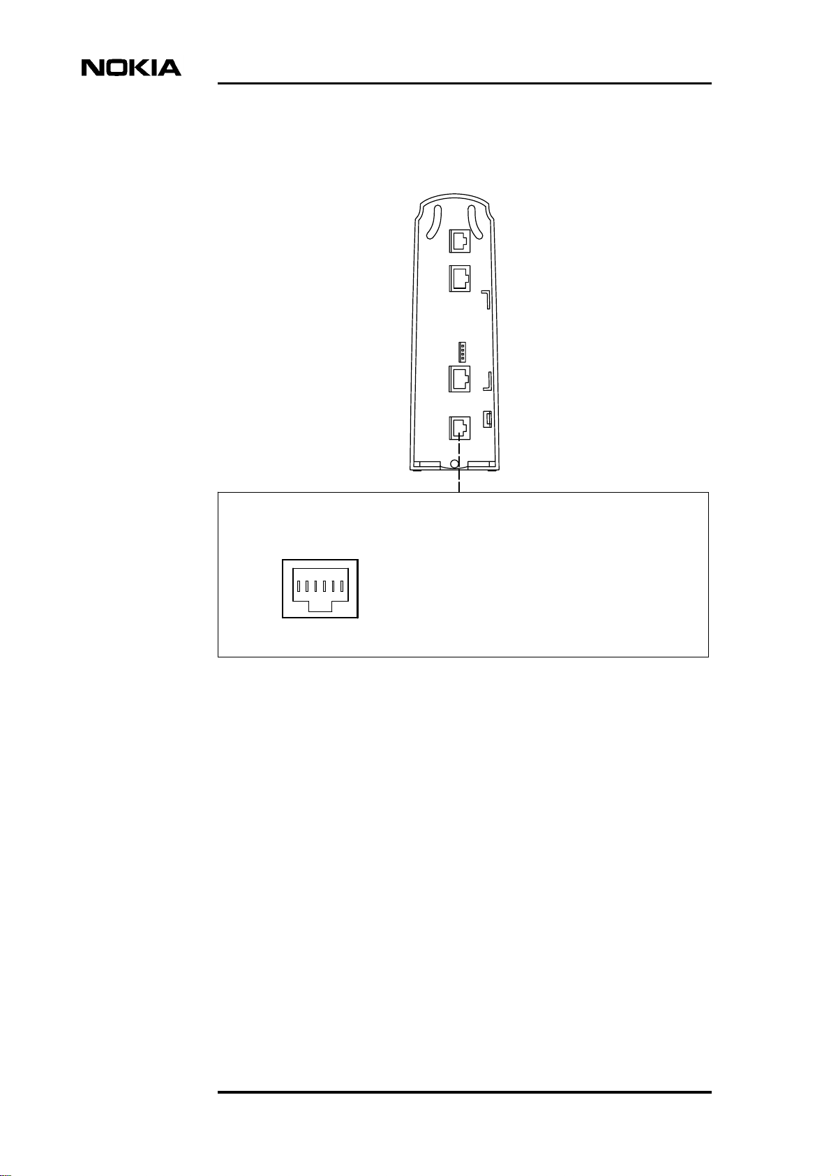
4.1 Line interface
DNT2Mi-fp Data Network Terminal User manual
6-pin modular jack, RJ-11
DSL Line
1
Figure 6. Line interfaces of DNT2Mi-fp
4.2 Power supply
DNT2Mi-fp can be fed with either, 48VDC or remotely via ACL2i through the
line. It is also possible to use a AC to DC converter (110/230VAC to 48VDC) to
feed power to the DNT2Mi-fp.
Pin
Line interface
1.
6
-
Line 1a
Line 1b
2.
3. Not connected
4. Not connected
5.
Line 2a (not in use in 2-w mode)
Line 2b (not in use in 2-w mode) *)
6.
not connected in T65690.01
*)
*)
14 (60) © Nokia Corporation DN0445814
Nokia Proprietary and Confidential Issue2-0en
Page 15
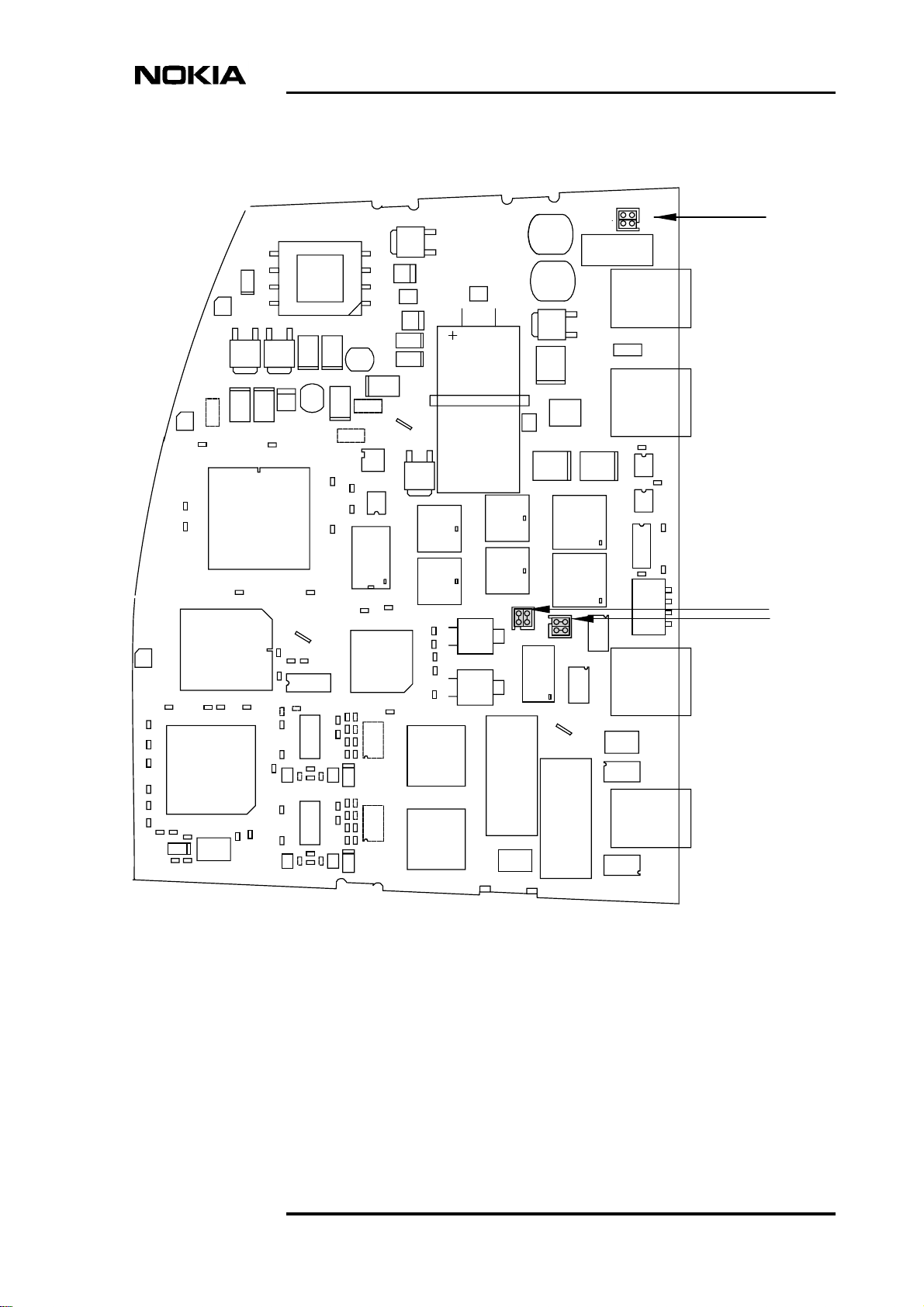
Selection of Power Supply option is done by strapping
Rear panel
Q4
L8
NR4
NR4
VDR1
D4
T4
D7
C23
C18
L9
LD1
D8
C42
D5
L11
C43
C33
C34
D6
C35
L10
C28
ST3
LD2
C186
17
18
C180
C181
50
51
C183
13
14
LD3
C105
72
R223
73
R287
C104
TP13
C103
R241
108
109
TP14
R245
C102
TP15
R270
C123
R232
R235
IC9
20
21
C106
C109
IC29
C122
OSC1
R240
D9
C27
C188
117
1
116
IC10
84
83
C184
5
4
C147
1
C85
R136
IC5
30
29
R135
R229
TP10
C107
R226
TP11
1
37
TP12
C131
36
IC25
14
C128
R261
C108
R262
C138
R268
1
1
C117
144
C101
IC26
14
C114
R236
C126
R237
R266
ST2
C29
ST1
NR1
C187
R199
C148
C185
Q2
IC17
OSC2
C61
C62
40
41
60
61
R246
R244
28
C130
R250
R252
C129
R247
R248
15
R256
R255
C136
C127
R267
R210
28
R209
C116
R215
R216
C115
R211
R212
R225
15
R224
C124
C113
R265
L22
L21
IC7
21
C71
20
C64
C69
1
80
C70
C63
C17
Banduit
L24
L26
X2
C73
X1
T3
T2
L25
L27
NR3
C58
GA1
Q1
~
DB1
+-~
L1
C2
-
+
DB3
~
~
T1
C53
6
1
F1
18
-
+
DB2
~
~
L3
C139
L6
NR2
L12
L13
18
GA2
L20
16
L23
J1
J3
C161
IC24
C160
IC23
R304
IC22
R286
SW1
1
NR3
NR2
J4
J2
Figure 7. Strapping instruction for Power Supply
DN0445814 © Nokia Corporation 15 (60)
Issue 2-0 en Nokia Proprietary and Confidential
Page 16
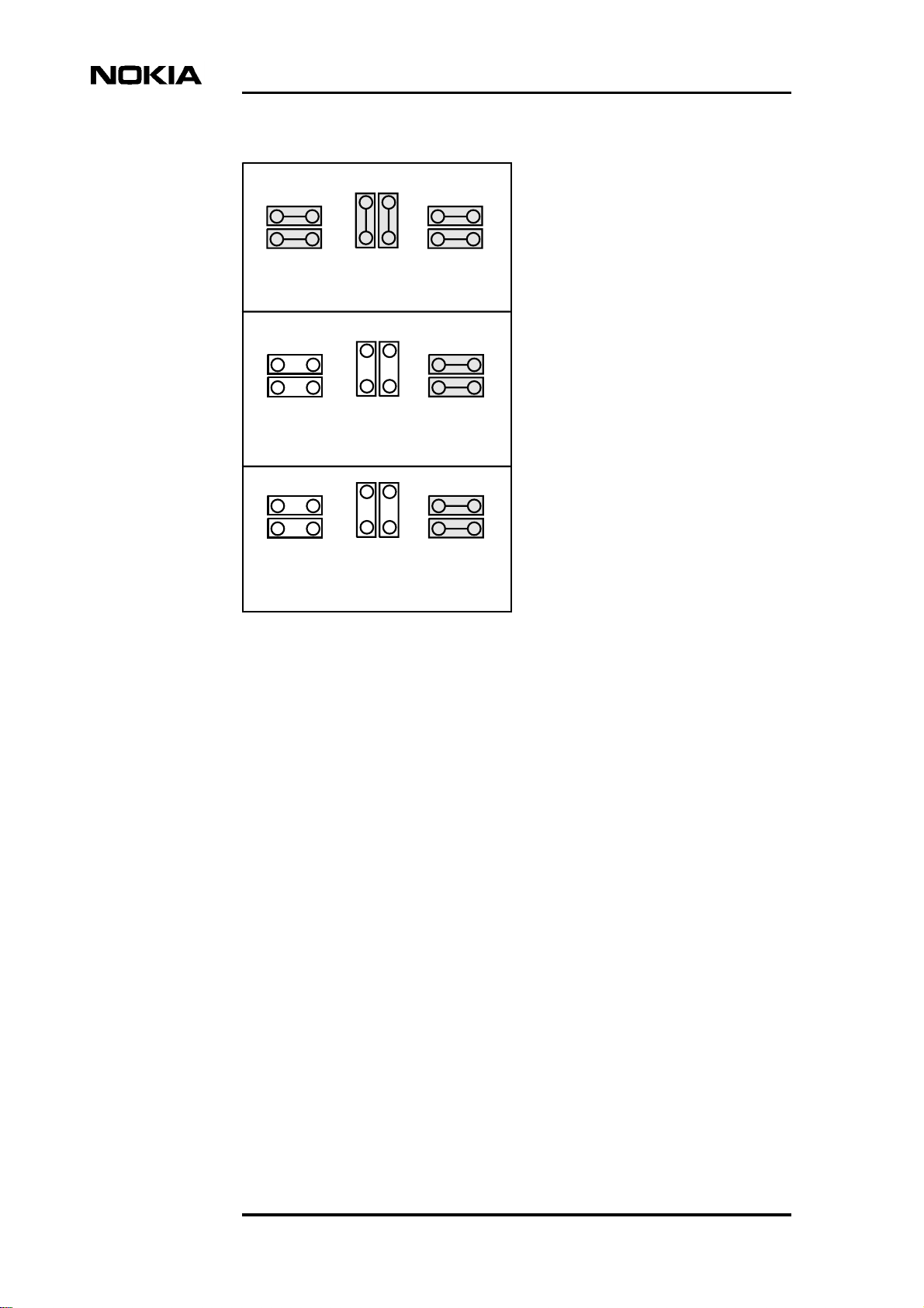
NR2 NR3 NR4
Remote Power Supply (default)
NR2 NR3 NR4
48V DC Supply
DNT2Mi-fp Data Network Terminal User manual
NR2 NR3 NR4
External AC/DC converter Supply
Figure 8. Power supply options
16 (60) © Nokia Corporation DN0445814
Nokia Proprietary and Confidential Issue2-0en
Page 17
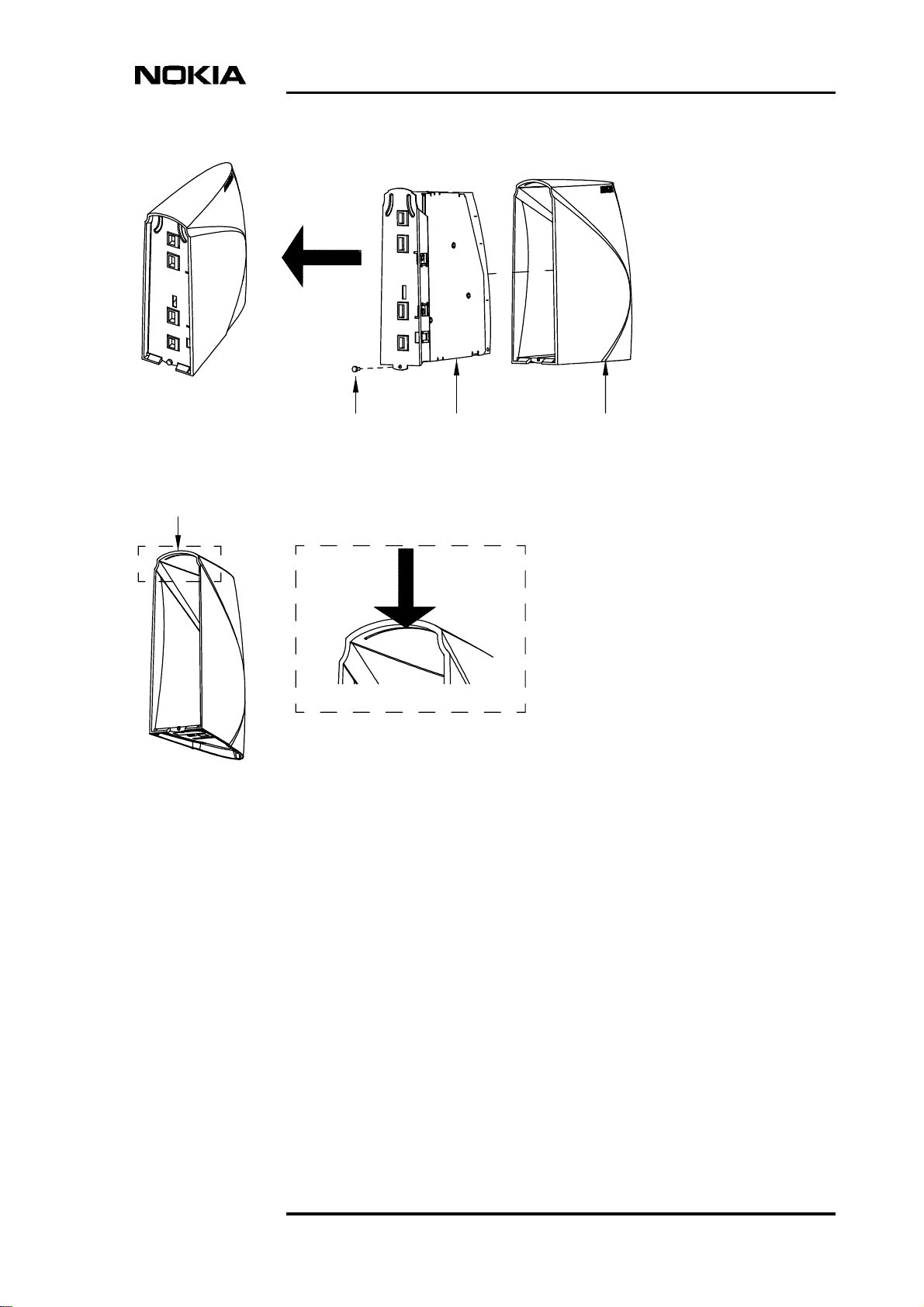
Assembled state
Torx 8 - screw1
2
Motherboard
Shell
3
Rear panel
1
2 3
Groove that supports
the back plate
(see detail)
Removal instruction:
1. Remove torx-screw with specified tool
2. Pull back plate along with motherboard using reasonable force out of the shell
3. Note that the back plate is supported from its upper end to the shell
Figure 9. How to open the DNT2Mi-fp
DN0445814 © Nokia Corporation 17 (60)
Issue 2-0 en Nokia Proprietary and Confidential
Page 18
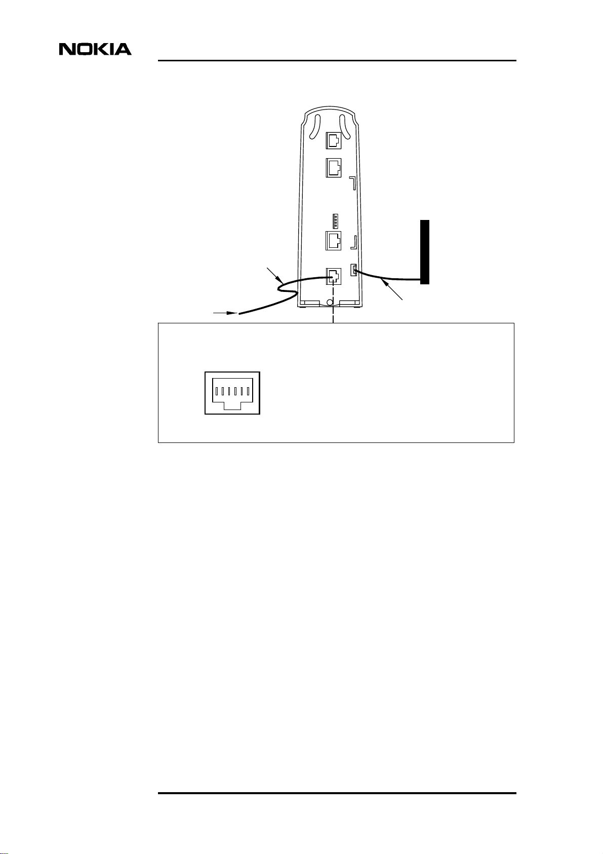
DSL Line
cable
DNT2Mi-fp Data Network Terminal User manual
Earthing bar
Remote power
supply
6-pin modular jack, RJ-11
DSL Line
1
6
-
Pin
Line interface
1.
Line 1a
Line 1b
2.
3. Not connected
4. Not connected
5.
Line 2a (not in use in 2-w mode)
Line 2b (not in use in 2-w mode) *)
6.
not connected in T65690.01
*)
Figure 10. Remote power feed through line
1.0 mm wire
2
*)
18 (60) © Nokia Corporation DN0445814
Nokia Proprietary and Confidential Issue2-0en
Page 19

48VDC
Rear panel
Earthing bar
6-pin modular jack, RJ-11
48VDC
1
6
-
Figure 11. 48VDC supply connector
1.0 mm wire
2
Pin+48VDC interface
1.
2.
3.
N.C 48VDC
4.
5.
-
6.
DN0445814 © Nokia Corporation 19 (60)
Issue 2-0 en Nokia Proprietary and Confidential
Page 20

110/230 V AC
DNT2Mi-fp Data Network Terminal User manual
48VDC
AC/DC
converter
Earthing bar
2
1.0 mm
wire
Figure 12. AC 110/230V supply through external AC/DC converter
20 (60) © Nokia Corporation DN0445814
Nokia Proprietary and Confidential Issue2-0en
Page 21

4.3 Terminal interface
G.704/2M
Rear panel
8-pin modular jack,
RJ-45
G.704/2M
18
-
Pin Data interface
1.
TX (OUT)
2.
3. SHIELD
4.
RX (IN)
5.
6. SHIELD
Not connected
7.
Not connected
8.
Figure 13. Symmetrical G.704/2M interface
DN0445814 © Nokia Corporation 21 (60)
Issue 2-0 en Nokia Proprietary and Confidential
Page 22

DNT2Mi-fp Data Network Terminal User manual
22 (60) © Nokia Corporation DN0445814
Nokia Proprietary and Confidential Issue2-0en
Page 23

5 Management
The Local Management Interface (LMI) is located at the rear panel (see Figure
12). The interface is used to manage DNT2Mi-fp with Service Terminal (V.11)
and Macro Service Terminal Emulator (typically V.28) running on a PC or with
other Nokia management software.With ST it is also possible to manage other
network elements through the DNT2Mi-fp
Use of signal 108 when using MSTE
If signal 108 is on it will disconnect the DNT2Mi-fp from the management
network and no other network elements can be managed through the DNT2Mi-fp.
Management
If signal 108 is off then it is possible to manage the network elements through the
DNT2Mi-fp.
Electrically, management interface signals comply with ITU-T V.28 or V.11. The
selection is made using rear panel DIP switch.
DN0445814 © Nokia Corporation 23 (60)
Issue 2-0 en Nokia Proprietary and Confidential
Page 24

DNT2Mi-fp Data Network Terminal User manual
LMI
DIP Switch
Local management connector
(RJ-45)
1
8
-
LMI Interface type selection
V.11
1
V.28
1
V.28
V.11
1. 107 (HiZ) Tx b (OUT)
2. 108 (IN)
3. 109 (HiZ) Tx a (OUT)
4. SG SG
5. 103 (IN) Rx b (IN)
6. 104 (OUT)
7. 105
8. 106
]
Rx a (IN)
Figure 14. Local management connector
Table 1. Management interface cables
Code Name Connector type Length
E64320.01 Management cable (PC
–> DNT2Mi-fp)
E62731.01 Management cable (ST
–> DNT2Mi-fp)
ST = Service Terminal
PC = PC + Service Terminal Emulator
D9F/RJ45 3 m
D15/RJ45 3 m
24 (60) © Nokia Corporation DN0445814
Nokia Proprietary and Confidential Issue2-0en
Page 25

DIP
-switc
h
Management
DNT2Mi-fp
- - -
Tx Rx
Tx
Tx Rx Tx Rx
Rx
Q1 management bus
DNT2Mi-fp
DSL Line
Q1 management through Line
Figure 15. Q1 management bus
Up to 32 DNT2Mi-fp units can be connected to the same Q1 bus of V.11-type via
a local management interface.
DN0445814 © Nokia Corporation 25 (60)
Issue 2-0 en Nokia Proprietary and Confidential
Page 26

DNT2Mi-fp Data Network Terminal User manual
26 (60) © Nokia Corporation DN0445814
Nokia Proprietary and Confidential Issue2-0en
Page 27

6 Commissioning
This chapter describes the most common items that need to be checked before
DNT2Mi-fp is taken into use.
DNT2Mi-fp is ready to operate after the power supply (AC/DC converter, DC or
remote power) and port and line cables are connected. However, identifications
and settings should be checked and, if required, statistics and error counter should
be reset.
DNT2Mi-fp can be configured, tested and controlled via:
Commissioning
• Service Terminal (using Q1)
• Macro Service Terminal Emulator or Craft Terminal running on a PC
(using Q1)
• Other Nokia management products, such as Nokia NMS, can be used for
the same purpose.
Menu structure for Q1 management is shown in chapter Factory Settings.
Note
It can take up to 60 seconds to save the altered settings. If the power is switched
off during this time, the new settings will be lost. During the saving process, you
can use the equipment normally.
Automatic power-up test
When the power is switched on, the unit performs an automatic self test, which is
used to check the most vital operational functions of the equipment.
During the power-up test, the LEDs are lit in the following sequence:
1. All 3 LEDs are lit for 10 seconds.
2. The green power LED is blinking and other are off for 10 seconds during
startup and self test.
3. The green power LED is lit and DNT2Mi-fp is ready for use.
DN0445814 © Nokia Corporation 27 (60)
Issue 2-0 en Nokia Proprietary and Confidential
Page 28

If errors were found during the power-up test, more information on this can be
found in the Self test menu (Q1: 5,4,0).
6.1 Management
DNT2Mi-fp can be managed through the line connection or local management
port LMI.
The following items need to be checked:
Q1 transmission speed (Q1: 6,1,1)
The Q1 transmission speed needs to be set to match the system management
speed.
Q1 address (Q1: 6,1,2)
The equipment needs a Q1 address to be visible in the NMS systems. You must
give a unique address to each equipment.
DNT2Mi-fp Data Network Terminal User manual
You can also enter a name for the equipment by using the command 4,7,2,1
Q1 management via line (Q1: 6,1,3)
The routing of the management must be defined to correspond with the system.
Note
The address setting has the following restrictions:
• The address 4095 must not be given if the equipment is connected to an
NMS bus. This address is a common (broadcast) address.
• The address 4094 is reserved for PC-TMC/STE use (general address for the
PC interface unit).
• The address 0 is reserved for PC-TMC/STE use (default address for the PC
interface unit).
6.2 Timing source
Before connecting DNT2Mi to a network, you need to know how the network is
timed.
DNT2Mi-fp can receive timing information through the Line or Port interfaces.
28 (60) © Nokia Corporation DN0445814
Nokia Proprietary and Confidential Issue2-0en
Page 29

DNT2Mi-fp can also be used as a network timing source using the unit's Internal
timing circuits.
DNT2Mi-fp can also be used as Transparent timing. This means that both E1
transmission directions are independent.
6.3 Line settings
You have to check the following items:
Line interface (Q1: 6,3,3)
The line interface settings determine line SHDSL mode, connection rate and use
of wires.
Typically, DNT2Mi-fp is configured as STU-R, Rate Adaptive. The Rate
Adaptive mode automatically adapts the requested fixed line rate to STU-C.
Commissioning
Line interface
SHDSL mode
STU-C Fixed
4-wire
Line Rate
n=3...32
Figure 16. Principle of the line interface menu
Line Rate
n=6...32
2-wire2-wire
STU-R Rate Adaptive
4-wire
Power backoff (Q1: 6,3,6)
Select this option to enable or disable transmit power reduction on short loops.
DN0445814 © Nokia Corporation 29 (60)
Issue 2-0 en Nokia Proprietary and Confidential
Page 30

Line alarms (Q1: 6,3,8 and 6,3,9)
The BER alarm limit and alarm severity have to be checked.
6.4 Port settings
You have to check the following items:
Port framing (Q1: 6,4,1)
Check that the 2M data interface settings are compatible with the equipment they
are connected to.
No frame (Q1: 6,4,1,1)
Alternative if full 2M is needed and no framing is required. Port statistics is not
available. Only UAT is calculated if there is no G.703 signal present at the port.
DNT2Mi-fp Data Network Terminal User manual
Basic frame of CRC multiframe (Q1: 6,4,1,2 or 6,4,1,3)
Alternative if fractinal 2M is needed. In this case payload rate is n
31) and one time slot is reserved for framing. Frame is terminated at DNT2Mi-fp
port interface. Port statistics is available.
Monitoring Basic frame or CRC multiframe (Q1: 6,4,1,4 or 6,4,1,5)
Alternative if fractinal 2M is needed. In this case payload rate is n
31) and one time slot is reserved for framing. Frame is not terminated at
DNT2Mi-fp port interface, and all T0 bits (Sa, A, E and framing bits) goes
through the port interface. Port statistics is available.
Port alarms (Q1: 6,4,8 and 6,3,9)
The BER alarm limit and alarm severity have to be checked.
6.5 Protection settings
Password (Q1: 10,1 and 10,4)
DNT2Mi-fp settings can be protected with a password.
*
64 (n = 1 to
*
64 (n = 1 to
If password is required (Q1: 10,4,2,2) and correct password has given (Q1:
10,1,[password] ), then the Q1 user has privileges to make configurations.
Privileges time out is defined by Q1 menu 10,4,1 (1 to 1000 min).
30 (60) © Nokia Corporation DN0445814
Nokia Proprietary and Confidential Issue2-0en
Page 31

Default password for DNT2Mi-fp protection is DNT2Mi, and it can change by
menu option (Q1: 10,4,3).
6.6 Measurements
After all the settings have been checked, it is recommended that you carry out a
line quality and BER test.
Note
Before starting the BER test, reset all statistics and error counters. Read statistics
and error counters after the BER test.
Noise margins, Rx and Tx line levels, and attenuations (Q1: 7,1...4)
Establish a link between two units. After the line is up, check the noise margin,
Rx level, and line attenuation from the Measurements menu.
Commissioning
After the tests
Check that all alarms have disappeared and the statistics are still correct.
DN0445814 © Nokia Corporation 31 (60)
Issue 2-0 en Nokia Proprietary and Confidential
Page 32

DNT2Mi-fp Data Network Terminal User manual
32 (60) © Nokia Corporation DN0445814
Nokia Proprietary and Confidential Issue2-0en
Page 33

7 Maintenance
This chapter describes what general information and statistics you can get on the
equipment to be monitored. It also deals with possible alarms and faults. You can
access all this information using Q1 menus. The menus are described in figure 20
and onwards.
7.1 Getting general information
Maintenance
The Identifications menu, branch 4 on the Q1 main menu, gives the name and
type of the unit to be monitored, the codes and versions of HW unit and program
to be used and some installation information.
Identifications
Equipment type:
DNT2Mi-fp G.704 2w (T65690)
Equipment name:
DNT2Mi-fp
Installation date
First:
Last:
Installed by
HW:
E65691.01
ASW:
S65692.01 A0
Serial number:
4H0415
Figure 17. Example of general information
DN0445814 © Nokia Corporation 33 (60)
Issue 2-0 en Nokia Proprietary and Confidential
Page 34

In this menu the name of the supervised unit, installation date and installer are
changeable. To change these parameters select Modify: Q1 menu option 4,7,2,1
for name, 4,7,4,1,1 for date and 4,7,4,1,2 for installer. Note that the maximum
lengths are 15 characters for date and name and 20 characters for installer. There
are two dates for installation date, First and Last. In very first time the First and
Last gets the same date (Q1: 4,7,4,1,1), and after that only the Last gets new value
(Q1: 4,7,4,1,1).
7.2 Monitoring alarms
The Fault display (see the figure below) gives error information concerning the
unit chosen. The information includes the name, which the user has given to the
supervised device, supervision block, for example line or port, the type of a fault,
and the fault status shown by the alarm class (A = urgent, B = non-urgent, AS =
urgent, service alarm).
*DNT2Mi (AS)
Line:
-no incoming signal
DNT2Mi-fp Data Network Terminal User manual
Figure 18. Example of Fault display
In the example above, the first line consists of the name given to the supervised
device and alarm class (AS), the second line shows the supervision block, and the
third line the type of the fault.
Table below shows alarm information from Port and Line interfaces and alarms
from the equipment itself.
DNT2Mi-fp
SB 0, MODEM
Code Severity Q1 message
0x7c AS Sync. fault in clock recovery
0x80 AS Fault equipment
0x91 A,B Temperature error
34 (60) © Nokia Corporation DN0445814
Nokia Proprietary and Confidential Issue2-0en
Page 35

SB 1, Port
Code Severity Q1 message
0x15 B Loop to interface
0x32 AS Loss of incoming 2 M signal
0x42 B Ais 2 M
0x51 AS Loss of frame alignment
0x56 B CRC multiframe alignment lost
0x63 AS, A, B BER > 1 E-3
0x66 AS, A, B BER > 1 E-6
0xb3 B Far-end alarm
Maintenance
SB 2, Line
Code Severity Q1 message
0x15 B Loop to interface
0x30 AS Loss of incoming signal
0x51 AS Loss of frame alignment
0x63 AS, A, B BER > 1 E-3
0x66 AS, A, B BER > 1 E-3
0xb0 B Far-end alarm 1
0xb3 B Far-end alarm
7.3 Testing
DNT2Mi-fp tests can be controlled using Q1 menus. The following tests are
available for testing a DNT2Mi terminal:
DN0445814 © Nokia Corporation 35 (60)
Issue 2-0 en Nokia Proprietary and Confidential
Page 36

DNT2Mi-fp Data Network Terminal User manual
Q1 management Automatic controll Note
Equipment tests
Power up test After power is switched on
Self test Self test (5.4) During self test
management and line
connection is
disconnected.
Line interface test
Network test
loop
Data coming
from the line is
looped back to
the line.
Port interface test
Local test loop
Data coming
from the DTE is
looped back to
the DTE.
Loop to Line(5,3,2) See Figure “Network
test loop” after this
table.
Loop to Port(5,2,3) See Figure “Local test
loop” after this table.
DTE
Port
Interface
Line
Interface
AIS
Figure 19. Local test loop
DTE
AIS
Port
Interface
Line
Interface
Figure 20. Network test loop
36 (60) © Nokia Corporation DN0445814
Nokia Proprietary and Confidential Issue2-0en
Page 37

7.4 Checking measurements and statistics
The parameters that can be viewed through the Q1 menus Measurement (main
menu branch 7 and Statistics (main menu branch 8) are listed below.
Measurements via Q1
• Noise margin
• Rx level
• Tx level
• Line attenuation
• Line voltage (remote-powered)
Attenuation can be 0 to 41 dB.
Maintenance
Monitoring a line
Tx level
Line 1 or 2: xx dBm xx = +7.5 to +14.5 dBm
Rx level
Line 1 or 2: xx dBm xx = +14.5 to -35 dBm
Noise margin
Line 1 or 2: xx dB xx = 0 to +15 dB
Attenuation
Line 1 or 2: xx dB xx = 0 to 50 dB
Noise margin
+15...1 dB, expected BER < 10
0 dB, expected BER 10
-7
-7
DNT2Mi-fp statistics
Signal qualities of the selected 15-minute periods (100) and 24-hour periods (30)
and since the last reset, according to Rec. G.826, are indicated by the quality
parameters in the table below.
DN0445814 © Nokia Corporation 37 (60)
Issue 2-0 en Nokia Proprietary and Confidential
Page 38

Table 2. Statistics values via Q1
DNT2Mi-fp Data Network Terminal User manual
Information Abbreviation
Description
and/or ratio
Total time TT Time passed since the last reset.
Unavailability
time
Errored seconds ES
Severely errored
seconds
Backgroundblock
errors
Unavailability
time ratio
Errored seconds
ratio
UAT
(Rx, Tx)
(Rx, Tx)
SES
(Rx, Tx)
BBE
(Rx)
UATR
(Rx, Tx)
ESR
(Rx, Tx)
Time during which severely
errored seconds have occurred.
Number of errored seconds.
Number of seconds during which
e 30% blocks are errored.
Number of errored blocks except
blocks during severely errored
seconds and unavailable time.
The block size depends on the
used line rate.
Ratio of unavailability time to the
total time during the last 15
minutes or 24 hours.
Ratio of errored seconds to the
total of seconds in the available
time during the last 15 minutes
or 24 hours.
Severely errored
seconds ratio
Backgroundblock
error ratio
SESR
(Rx, Tx)
BBER
(Rx)
Ratio of severely errored
seconds to the total of seconds
in the available time during the
last 15 minutes or 24 hours.
Ratio of background block errors
to the total of blocks during the
last 15 minutes or 24 hours,
except blocks during severely
errored blocks and unavailable
time.
System counters (Q1: 8,3)
Number of CPU resets and the time passed since the last reset.
38 (60) © Nokia Corporation DN0445814
Nokia Proprietary and Confidential Issue2-0en
Page 39

8 Technical specifications
Table 3. DNT2Mi-fp dimensions
Width 56 mm
Height 173 mm
Depth 138 mm
Weight 510g
Technical specifications
Table 4. Environmental and mechanical
Storage ETSI ETS 300 019-2-1 class 1.2
Operation ETSI ETS 300 019-2-3 class 3.2
Transportation ETSI ETS 300 019-2-2 class 2.3
Table 5. Line interface (in accordance with ITU-T G.991.2
Recommendation)
Connector RJ-11
Line type 2 – wire or 4 – wire
Nominal impedance 135 ohms
Line code TC-PAM
Tx power (0 dB power backoff) 11,5 dBm @ 135 ohm (192 and 256
kbit/s)
13,5 dBm @ 135 ohm (320 to 1984
kbit/s)
14,5 dBm @ 135 ohm (2048 kbit/s)
Signal bandwidth 0...300 kHz (2048 kbit/s, 2-w, -3 dB)
Line interface 192 kbit/s to 2048 kbit/s (n x 64 bit/s)
DN0445814 © Nokia Corporation 39 (60)
Issue 2-0 en Nokia Proprietary and Confidential
Page 40

DNT2Mi-fp Data Network Terminal User manual
Table 6. 2 M data interface
Interface type G.703 (2 Mbit/s) 120-ohm symmetrical
Maximum allowed timing jitter at receiver
timing
Maximum generated timing jitter at
receiver timing
Frame structure According to ITU-T G.704
Relevant ETSI ONP standards ETS 300 246, ETS 300 247,
Electrical characteristics According to ITU-T G.703 2048 kbit/s
Common mode rejection 50 dB
Return loss (120 or 75 ohms;1 kHz to 4.5
MHz)
Connector RJ-45
According to ITU-T G.823
According to ITU-T G.823
ETS 300 418, ETS 300 419
20 dB
Data lead time
Data lead-time means the time which is needed to transfer the data from the
incoming 2M data interface of ACL2i to the outgoing 2M data interface of
DNT2Mi-fp at the other end of the line.
The lead-time of the data from ACL2i to DNT2Mi-fp depends on the line rate
selected as follows:
40 (60) © Nokia Corporation DN0445814
Nokia Proprietary and Confidential Issue2-0en
Page 41

)
)
ms
4.0
3.5
3.0
2.5
2.0
1.5
1.0
0.5
Technical specifications
Data lead-time (ACL2i to DNT2Mi-fp
0.0
0
81216
4
20 24
28
32
n = 3 to 32 (192 kbit/ to 2048 kbit/s
DN0445814 © Nokia Corporation 41 (60)
Issue 2-0 en Nokia Proprietary and Confidential
Page 42

DNT2Mi-fp Data Network Terminal User manual
Figure 21. Max SHDSL reach with Remote Powering
The values marked in bold means that remote powering is limiting maximum
length.
Table 7. DNT2Mi-fp power supply
Power consumption
DNT2Mi-fp 5,5 W 4 - wire mode
4,5 W 2 - wire mode
Power supply (external AC/DC converter).
42 (60) © Nokia Corporation DN0445814
Nokia Proprietary and Confidential Issue2-0en
Page 43

Table 7. DNT2Mi-fp power supply (Continued)
Technical specifications
Voltage 90 to 264 V
Frequency 47 to 65 Hz
DC power supply
Voltage 48V (40V to 70V)
Remote power supply
Voltage 50 to 150 V on both pairs as generated through ACL2i
at central site
Start-up voltage Min. 90 V
AC
DC
Table 8. Mean time between failure (MTBF)
DNT2Mi-fp > 75 years
Electromagnetic compatibility (EMC) of DNT2Mi-fp complies with the
following specifications:
Table 9. Electromagnetic compatibility
EN 55022: 1998 Class B Emission, Information technology equipment
EN 55024: 1988 Immunity, Terminal equipment
EN 300286: 2000 EMC, Telecommunications equipment
Table 10. Safety
Safety IEC 60950-1 and IEC 60950-21 RFT-C
• Protective earthing and Basic insulation
AC Power supply:
• Surge protection: 2.5kV according to ITU-T Rec. K.45
DC Power supply:
• Surge protection: 0.5kV according to EN61000–4–5
Line Interface:
• Surge protection: 1.5kV according to ITU-T Rec. K.45
• 50 Hz common mode test according to ITU-T Rec. K.45
• 600V RMS common mode according to ITU-T Rec. K.45
DN0445814 © Nokia Corporation 43 (60)
Issue 2-0 en Nokia Proprietary and Confidential
Page 44

DNT2Mi-fp Data Network Terminal User manual
44 (60) © Nokia Corporation DN0445814
Nokia Proprietary and Confidential Issue2-0en
Page 45

9 Factory settings
The factory default values can be recalled from the Q1 menu path 6,7. The default
values are marked bold in Q1 menu chart.
Note
Recalling of factory settings can take up to 60 seconds.
Factory settings
Table 11. Service settings
Q1 speed: 4800
Q1 address: 2
Q1 via line: On
Table 12. Line interface settings
PSD symmetric
2 – wire
STU – R
Power backoff: On
Table 13. Data interface settings (E1)
No frame
National bits: 11111
Timing source: Line
DN0445814 © Nokia Corporation 45 (60)
Issue 2-0 en Nokia Proprietary and Confidential
Page 46

Table 14. Alarm limits
DNT2Mi-fp Data Network Terminal User manual
Temperature alarm:
Limit: 75
Severity: No alarm
Port BER alarm: Limit: E-3
Severity: B-level
Line BER alarm: Limit: E-3
Severity: B-level
o
C
46 (60) © Nokia Corporation DN0445814
Nokia Proprietary and Confidential Issue2-0en
Page 47

Appendix A. Q1 menu diagrams
General
The Q1 Main menu level contains the following 11 menus, of which those
available in DNT2Mi-fp are typed in boldface in the list below:
1. Fault display
2. Local alarm cancel
3. Reset local cancel
4. Identifications
5. Controls
6. Settings
7. Measurements
8. Statistics
Q1 menu diagrams
9. Testing
10. User priviliges
11. Miscellaneous
Factory settings are marked within brackets on the Q1 menus diagrams below.
DN0445814 © Nokia Corporation 47 (60)
Issue 2-0 en Nokia Proprietary and Confidential
Page 48

1 Fault display
2 Local alarm cancel *)
3 Reset local cancel *)
4 Identifications
5 Controls
6 Settings
7 Measurements
8 Statistics
9 Testing *)
10 User privileges
11 Miscellaneous *)
DNT2Mi-fp Data Network Terminal User manual
DNT-fp Identifications:
0 Display
1 Eq type
2 Eq name
4
4 Installation info
5 HW version
6 SW version
7 Modify
8 Serial number
DNT-fp controls:
0 Display
5
1 All test loops off
2 Port test loop
3 Line test loop
4 Self test
DNT-fp settings:
0 Display
1 Service options
6
2 Timing source
3 Line settings
4 Port settings
7 Load factory settings
DNT-fp measurements:
0 Display all
1 Noise margins
7
2 Rx levels
3 Tx levels
4 Attenuations
5 Supply voltage
6 Temperature
*) not implemented
Figure 22. Main Q1 menu structure
DNT-fp statistics:
1 Port statistics
8
2 Line statistics
3 System counters
99 Reset all statistics
DNT-fp privileges:
1 Password for privileges
10
3 Cancel privileges
4 Setting parameters
48 (60) © Nokia Corporation DN0445814
Nokia Proprietary and Confidential Issue2-0en
Page 49

4
DNT-fp Identifications:
0 Display
1 Eq type
2 Eq name
4 Installation info
5 HW version
6 SW version
7 Modify
8 Serial number
Q1 menu diagrams
4,0
Identifications
Equipment type:
DNT2Mi-fp G.704 4w (T65690)
Equipment name:
DNT2Mi-fp
Installation date:
First:2004-20-02
Last:2004-20-02
Installed by:
Installer
HW:
E65691.01 A
SW:
S65692.01 A0
Serial number:
4H04....
4,1
DNT2Mi-fp(G.704)
4,2
DNT2Mi-fp
4,4
Installation info:
Date:
First: 2004-02-20
Last: 2004-02-20
Installed by:
Installer
4,5
HW version:
E65691.01 A
4,6
SW version:
S65692.01 A0
4,7
4,8
Figure 23. Identifications menu
DN0445814 © Nokia Corporation 49 (60)
Issue 2-0 en Nokia Proprietary and Confidential
Page 50

4,7
Modify:
2 Eq name
4 Installation info
4,8
Serial number:
4H04...
4,7,2
Eq name:
0 Display
1 Modify
4,7,4
Installation info:
0 Display
1 Modify
DNT2Mi-fp Data Network Terminal User manual
4,7,2,1
Give new eq name:
Max 15 characters
4,7,4,1
Modify:
1 Date
2 Installed by
4,7,4,1,1
Give new Installation date:
yyyy-mm-dd
4,7,4,1,2
Give new Installer:
Max 20 characters
Figure 24. Identifications menu (continued)
50 (60) © Nokia Corporation DN0445814
Nokia Proprietary and Confidential Issue2-0en
Page 51

5
DNT-fp controls:
0 Display
1 All test loops off
2 Port test loop
3 Line test loop
4 Self test
Q1 menu diagrams
5,2
Port test loop:
0 Display
1 Port test loop off
2 Loop to Port
5,3
Line test loop:
0 Display
1 Line test loop off
2 Loop to Line
5,4
Self test:
0 Result of last ST
1 Start Self Test
Figure 25. Controls menu
5,4,1
Run Self test:
1 Yes
2 No
DN0445814 © Nokia Corporation 51 (60)
Issue 2-0 en Nokia Proprietary and Confidential
Page 52

The factory settings are marked within brackets.
6
DNT-fp settings:
0 Display
1 Service options
2 Timing source
(Line)
3 Line settings
4 Port settings
7 Load factory settings
6,1
Service options:
0 Display
1 Q1 Speed
2 Q1 Address
3 Q1 via line
7 Test time out limit
(4800)
(2)
(On)
(10)
12 Temperature alarm limit
13 Temperature alarm severity
6,1,1
Q1 speed:
0 Display
Set speed
600 ...9600
DNT2Mi-fp Data Network Terminal User manual
(75C)
(No alarm)
6,2
6,3
6,4
6,7
6,1,2
Q1 address:
0 Display
1 Modify
6,1,3
6,1,7
6,1,12
6,1,13
Figure 26. Settings menu structure
6,1,2,1
Give new address:
0 to 4094
52 (60) © Nokia Corporation DN0445814
Nokia Proprietary and Confidential Issue2-0en
Page 53

6,1,3
Q1 via line:
0 Display
1 On
2 Off
6,1,7
Test time out limit:
0 Display
1 to 64999 min
65000 no limit
6,1,12
Temperarure alarm limit:
0 Display
1 50C
2 55C
3 60C
4 65C
5 70C
6 75C
7 80C
8 85C
9 90C
Q1 menu diagrams
6,1,13
Temperarure alarm severity:
0 Display
1 No alarm
2 A-level alarm
3 B-level alarm
6,2
Timing source:
0 Display
1 Internal
2 Line
3 Port
4 Transparent
6,3
6,4
6,7
Figure 27. Settings menu structure (continued)
DN0445814 © Nokia Corporation 53 (60)
Issue 2-0 en Nokia Proprietary and Confidential
Page 54

DNT2Mi-fp Data Network Terminal User manual
6,4
6,7
6,100
6,3
Line settings:
0 Display
3 Line interface
6 Power backoff
8 BER alarm limit
9 BER alarm severity
6,3,3
6,3,3
Line interface
SHDSL mode:
1 STU-C (fixed)
2 STU-R (rate adaptive)
6,3,6
0 Display
1 On
2 Off
6,3,3
6,3,8
BER alarm limit:
0 Display
1 E-3
2 E-6
6,3,9
BER alarm severity:
0 Display
1 No alarm
2 A-level alarm
3 B-level alarm
4 AS-level alarm
(STU-R, 2w)
(On)
(E-3)
(B-level alarm)
6,3,3,1
Line if: STU-C
2/4-wire mode:
2 Two-wire
4 Four-wire
6,3,3,2
Line if: STU-R
2/4-wire mode:
2 Two-wire
4 Four-wire
The factory settings are marked within brackets.
psdS = Power spectral density mask,
Symmetric
32 = Line rate, the value of n x 64k
*) not in T65690.01
*)
6,3,3,1,2
Line if: STU-C, 2w, psdS
Give line rate
n = 3 .. 32
6,3,3,1,4
Line if: STU-C, 4w, psdS
*)
Give line rate
n = 6 .. 32 (even number)
*)
Figure 28. Settings menu structure (continued)
54 (60) © Nokia Corporation DN0445814
Nokia Proprietary and Confidential Issue2-0en
Page 55

Q1 menu diagrams
6,4
Port settings:
0 Display
1 Framing format
2 Sa bits usage
8 BER alarm limit
9 BER alarm severity
6,7
Load factory settings:
Are you sure?
1 Cancel
99 Yes
The factory settings are marked within brackets.
(No frame)
(E-3)
(B-level alarm)
6,4,1
Framing format:
0 Display
1 No frame
2 Basic frame
3 CRC multiframe
4 BF monitoring
5 CRC monitoring
6,4,2
Sa bits usage:
0 Display
1 Fill Sa4
2 Fill Sa5
3 Fill Sa6
4 Fill Sa7
5 Fill Sa8
6,4,8
BER alarm limit:
0 Display
1 E-3
2 E-6
6,4,9
BER alarm severity:
0 Display
1 No alarm
2 A-level alarm
3 B-level alarm
4 AS-level alarm
6,4,2,1..5
Give filling value:
0 or 1
Figure 29. Settings menu structure (continued)
DN0445814 © Nokia Corporation 55 (60)
Issue 2-0 en Nokia Proprietary and Confidential
Page 56

7
DNT-fp measurements:
0 Display all
1 Noise margins
2 Rx levels
3 Tx levels
4 Attenuations
5 Supply voltage
6 Temperature
DNT2Mi-fp Data Network Terminal User manual
NM = Noise margin
At = Attenuation
P = Pair
*) Not in T65690.01
7,0
At
NM
P
dB
#
xx
1:
2: xx xx xx xx *)
Line voltage xxV
Temperature xxC
7,1
Noise margins:
Pair 1 xx dB
Pair 2 xx dB *)
7,2
Rx levels:
Pair 1 xx dBm
Pair 2 xx dBm *)
7,3
Tx levels:
Pair 1 xx dBm
Pair 2 xx dBm *)
7,4
Attenuations:
Pair 1 xx dB
Pair 2 xx dB *)
7,5
Supply voltage:
xxV
7,6
Temperature:
xxC
dB
xx
Tx
dBm
xx
Rx
dBm
xx
Figure 30. Measurements menu structure
56 (60) © Nokia Corporation DN0445814
Nokia Proprietary and Confidential Issue2-0en
Page 57

8
DNT-fp statistics:
1 Port statistics
2 Line statistics
3 System counters
99 Reset all statistics
8,1
Port statistics:
3 Relative values
4 Absolute values
5 Reset statistics
8,1,3
Port stat relative:
1 15 min periods
2 24h periods
8,1,4
Port stat absolute:
1 15 min periods
2 24h periods
3 Since last reset
1) You can choose up to 100 15 min
periods or up to 30 24h periods
8,1,3,1..2
Give period 0 to 100:
(0=curr., 1=last, 2=prev., etc.)
1)
8,1,3,1..2, 0
15 min relative statistics:
P0 xxd xxh xxmin xxs
UATR
ESR
SESR
BBER
UATR
ESR
SESR
Q1 menu diagrams
(Rx):
(Rx):
(Rx):
(Rx):
(Tx):
(Tx):
(Tx):
xxxxx
xxxxx
xxxxx
xxxxx
xxxxx
xxxxx
xxxxx
8,2
8,3
8,1,4,1..2
8,1,4,3
Statistics since last reset:
TT xxd xxh xxmin xxs
UAT
ES
SES
BBE
UAT
ES
SES
(Rx):
(Rx):
(Rx):
(Rx):
(Tx):
(Tx):
(Tx):
xx
xx
xx
xx
xx
xx
xx
Figure 31. Statistics menu structure
Give period 0 to 100
(0=curr., 1=last, 2=prev., etc.)
1)
8,1,4,1..2,0
15 min absolute statistics:
P0 xxd xxh xxmin xxs
UAT
ES
SES
BBE
UAT
ES
SES
(Rx):
(Rx):
(Rx):
(Rx):
(Tx):
(Tx):
(Tx):
xx
xx
xx
xx
xx
xx
xx
DN0445814 © Nokia Corporation 57 (60)
Issue 2-0 en Nokia Proprietary and Confidential
Page 58

DNT2Mi-fp Data Network Terminal User manual
8,2
Line statistics:
1 Line status
3 Relative values
4 Absolute values
5 Reset statistics
8,2,3
8,2,4
8,3
System counters:
1 CPU reset counter
2 Time since reset
8,3,1
Line stat relative:
1 15 min periods
2 24h periods
Line stat absolute:
1 15 min periods
2 24h periods
3 Since last reset
8,2,4,3
RX statistics since last reset:
TT: xxd xxh xxmin xxs
UAT
ES
SES
BBE
CPU reset counter:
0 Display
1 Reset counter
Line1
xx
xx
xx
xx
8,2,3,1..2
Give period 0 to 100
(0=curr., 1=last, 2=prev., etc.)
8,2,4,1..2
Give period 0 to 100
(0=curr., 1=last, 2=prev., etc.)
Line2*)
xx
xx
xx
xx
1) You can choose up to 100 15 min
periods or up to 30 24h periods
*) Not in T65690.01
8,2,3,1..2,0
15 min relative statistics:
P0 xxd xxh xxmin xxs
UATR
ESR
SESR
BBER
8,2,4,1..2,0
15 min absolute RX statistics:
P0 xxd xxh xxmin xxs
UAT
ES
SES
BBE
Line1
xx
xx
xx
xx
(Rx):
(Rx):
(Rx):
(Rx):
Line2*)
xx
xx
xx
xx
Line1
xx
xx
xx
xx
Line2*)
xx
xx
xx
xx
Figure 32. Statistics menu structure (continued)
58 (60) © Nokia Corporation DN0445814
Nokia Proprietary and Confidential Issue2-0en
Page 59

Q1 menu diagrams
The factory settings are marked within brackets.
10
DNT-fp privileges:
1 Password for privileges
3 Cancel privileges
4 Setting parameters
10,1
Password for privileges:
Give password
10,3
Privileges cancelled
10,4
Setting parameters:
1 Password time out
2 Protections
(10)
(No protection)
3 New password
10,4,1
Password time out:
0 Display
1..1000 min
10,4,2
Protections
0 Display
1 No protection
2 Password required
10,4,3
Give new password:
1...7 characters
Figure 33. Privileges menu structure
DN0445814 © Nokia Corporation 59 (60)
Issue 2-0 en Nokia Proprietary and Confidential
Page 60

DNT2Mi-fp Data Network Terminal User manual
60 (60) © Nokia Corporation DN0445814
Nokia Proprietary and Confidential Issue2-0en
 Loading...