

Page 1
Installation Guide for
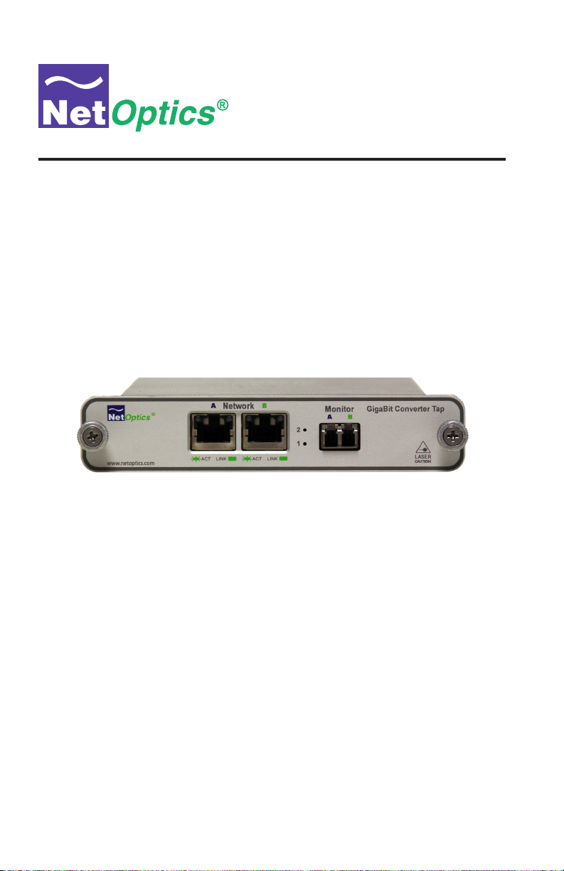
GigaBit TX to SX Tap
Model CVT-GCU/SX
Doc. PUBCVTGCUSXU Revised 03/07
Page 2

Page 3

Page 4

Table of Contents
Introduction . . . . . . . . . . . . . . . . . . . . . . . . . . . . . . . . . . . . . . . . . . . . . . . . . . . . . 1
Installation Guide for Gigabit TX/SX Tap
Key Features
Product Diagram
Connecting a GigaBit TX to SX Tap to the Network
Connecting a GigaBit TX to SX Tap to the Monitoring Device
Specications . . . . . . . . . . . . . . . . . . . . . . . . . . . . . . . . . . . . . . . . . . . . . . . . . . . 7
Warranty . . . . . . . . . . . . . . . . . . . . . . . . . . . . . . . . . . . . . . . . . . . . . . . . . . . . . . . 8
. . . . . . . . . . . . . . . . . . . . . . . . . . . . . . . . . . . . . . . . . . . . . . . . . . . . 1
. . . . . . . . . . . . . . . . . . . . . . . . . . . . . . . . . . . . . . . . . . . . . . . . . 2
. . . . . . . . . . . . . . . . . . . . . 3
. . . . . . . . . . . . . 5
Page 5

Installation Guide for Gigabit TX/SX Tap
PLEASE READ THESE LEGAL NOTICES CAREFULLY.
By using a Net Optics Tap you agree to the terms and conditions of usage set forth by Net Optics, Inc.
No licenses, express or implied, are granted with respect to any of the technology described in this
manual. Net Optics retains all intellectual property rights associated with the technology described in
this manual. This manual is intended to assist with installing Net Optics products into your network.
Trademarks and Copyrights
© 2007 by Net Optics, Inc. Net Optics® is a registered trademark of Net Optics, Inc. Additional company and product names may be trademarks or registered trademarks of the individual companies and
are respectfully acknowledged.
Additional Information
Net Optics, Inc. reserves the right to make changes in specications and other information contained
in this document without prior notice. Every effort has been made to ensure that the information in this
document is accurate. Net Optics is not responsible for typographical errors.
Page 6

Introduction
Net Optics GigaBit TX to SX Tap simplies connecting FX ber monitoring
and security devices to GigaBit copper network links. Convert TX to SX and
tap into the link with one device, reducing cost and complexity at the same
time. GigaBit TX to SX Taps support passive monitoring of GigaBit links at
speeds at 1000 Mbps.
Transparent Access
GigaBit TX to SX Taps establish permanent passive access ports without
introducing a point of failure or disturbing other network connections. These
passive Taps deliver full-duplex monitoring with zero impact on network traf-
c around the clock.
Security and Visibility
Without an IP address, monitoring devices are isolated from the network,
dramatically reducing their exposure to attacks. However, the monitoring
device connected to the Tap still sees all full-duplex trafc as if it were in-line,
including Layer 1 and Layer 2 errors.
Simply Plug It In
Full-duplex monitoring is a snap with supplied cables. All networking and
monitoring cables necessary for plug and play deployment are included with
the Tap
Installation Guide for Gigabit TX/SX Tap
Reliability
For extra uptime protection, Net Optics GigaBit TX to SX Taps offer
redundant power connections. Should the primary power source fail, the Tap
automatically switches to the backup power source. Power LEDs on the front
of the Tap indicate the current power source – even if power is lost and reap-
plied, there is always zero delay to network trafc.
Key Features
Passive, Secure Technology
• Provides passive access at speeds at 1000 Mbps without data stream
interference or introducing a point of failure
• Access GigaBit copper links with SX ber devices without a separate
converter
• Permanent in-line installation without affecting network performance
1
Page 7

Monitor A/B
SX
Network B
TX
Network A
TX
LED
Indicators
BA
www.netoptics.com
GigaBit TX to SX Converter Tap
LINK ACT
1
2
LASER
CAUTION!
BA
Monitor
®
Network
LINK ACT
Key Features (continued)
Passive, Secure Technology
• Passes all full-duplex trafc (including errors) from all layers for
comprehensive troubleshooting
• No IP address is needed for the Tap or monitoring device, enhancing
monitoring security
• Redundant power ensures monitoring uptime
• Fully IEEE 802.3 compliant
Ease of Use
• LED indicators show redundant power and link status
• Front-mounted connectors make installation and operation quick and easy
• Silk-screened application diagram illustrates all connections for easy
deployment
• Optional 19-inch rack frames hold up to 3 or 12 Taps
• Tested and compatible with all major manufacturers’ monitoring devices,
including protocol analyzers, probes, and intrusion detection/prevention
systems
Support
• Net Optics offers free technical support throughout the lifetime of your
purchase. Our technical support team is available from 8 am to 5 pm Pacic
Time, Monday through Friday at +1 (408) 737-7777 and via email at
ts-support@netoptics.com. FAQs are also available on Net Optics website
at www.netoptics.com.
Installation Guide for Gigabit TX/SX Tap
Product Diagram
Figure 1.
2
Page 8

Installation Guide for Gigabit TX/SX Tap
®
www.netoptics.com
Network
Monitor
1
2
GigaBit Converter TapGigaBit Converter Tap
A
ABB
ACT LINK ACT LINK
LASER
CAUTION!
To network switch or router
To network switch or router
Connecting a GigaBit TX to SX Tap to the Network
1. Unpack the Tap and verify that you have all components, and obtain the
required cables needed to successfully install the unit.
2. Connect Network Port A to the appropriate switch, server or router using a
CAT5E RJ45 straight-thru cable. This will act as your DCE interface.
3. Connect Network Port B to the appropriate switch, server or router using a
CAT5E RJ45 straight-thru cable. This will act as your DTE interface.
4. Verify that the Tap Network Ports are cabled in-line between two devices.
Link Fault Signaling
The Tap negotiates separately with each side of the full-duplex link,
detecting if either side fails. In the event of a failure, the Tap ceases negotiation with the remaining side, enabling a clean fail-over to a redundant
network connection (if one is available).
Figure 2.
3
Page 9

Installation Guide for Gigabit TX/SX Tap
Connecting a GigaBit TX to SX Tap to the Monitoring
Device
1. Supply power to the Tap using the 2 redundant power supplies included
with the unit. Verify that the Power LED illuminates.
2. Using a Net Optics Custom Monitor Cable, connect the single-duplex end
to the Tap Monitor Port A/B.
3. Connect the twin-duplex end of the cable labeled DCE into the appropriate
monitoring device port to monitor the DCE link.
4. Connect the other twin-duplex end to the appropriate monitoring device
port to monitor the DTE link.
5. Compare the LEDs on the Tap to the chart below to verify correct setup:
PWR1: Power 1. This LED illuminates (Green) when device is powered
up.
PWR2: Power 2. This LED illuminates (Green) when redundancy is
powered up.
LK: Link. This LED illuminates (Green) when link is established with
another device
Tx: Transmit. This LED illuminates (Green) when UTP port is transmitting
a signal.
Rx: Receive. This LED illuminates (Green) when UTP port is receiving a
signal.
Additional GigaBit TX/SX Tap LEDs are located in the upper left and
right hand corners of the RJ45 connectors for Port A and Port B.
• Link Indicator: Located in the upper right hand corner. If a good link is
established, the LED illuminates a steady green. If there is current activity
on this link, the LED ashes.
Note: The SC connectors on the Custom Analyzer Cable contain
RX connections only.
4
Page 10

Installation Guide for Gigabit TX/SX Tap
To monitoring device
®
www.netoptics.com
Network
Monitor
1
2
GigaBit Converter TapGigaBit Converter Tap
A
ABB
ACT LINK ACT LINK
LASER
CAUTION!
Connecting a GigaBit TX to SX Tap to the Monitoring
Device
Figure 3.
5
Page 11

Specications
Splitter Specications:
Split Ratio: 50/50
Fiber Type: Multimode Corning 62.5/125µm, wavelength 850nm
Insertion Loss: Network Port: ≤ 4.5 dB
Monitor Port: ≤ 4.5 dB
Operating Specications:
Operating Temperature: 10˚C to 55˚C
Storage Temperature: 0˚C to 70˚C
Relative Humidity: 10% min, 95% max, non-condensing
Mechanical Specications:
Power Supply: Input: 100-240 VAC, 47-63 Hz, 0.5A
(AC100-125V, 50-60Hz, 30VA for Japan)
Output: 12V, 1.5A (5V, 2.4A for UK and Japan)
Dimensions: 1.125" high x 6.5" deep x 4.5” wide
Connectors:
(1) Duplex SC connector (monitoring port)
(2) RJ45, 8 pin connectors (network ports)
Installation Guide for Gigabit TX/SX Tap
Cable Interface:
Copper Cable Type: 22-24 AWG unshielded twisted pair cable, CAT5E
Fiber Optic Interface:
Laser: Class I, eye-safe, laser emitter type. These Class I Lasers conform
to the applicable requirements per US 21 CFR (J) and EN 60825-1, also
UL 1950 applications.
Optical Transmitter Wave Length: 850 nm nominal
Output Power: -9.5 dB min, -4.0 dB max
Optical Receiver Input Sensitivity: 0 dB min, -17 dB max
6
Page 12

Installation Guide for Gigabit TX/SX Tap
Limitations on Warranty and Liability
Net Optics offers a limited warranty for all its products. IN NO EVENT SHALL NET OPTICS, INC.
BE LIABLE FOR ANY DAMAGES INCURRED BY THE USE OF THE PRODUCTS (INCLUDING BOTH HARDWARE AND SOFTWARE) DESCRIBED IN THIS MANUAL, OR BY ANY
DEFECT OR INACCURACY IN THIS MANUAL ITSELF. THIS INCLUDES BUT IS NOT LIM-
ITED TO LOST PROFITS, LOST SAVINGS, AND ANY INCIDENTAL OR CONSEQUENTIAL
DAMAGES ARISING FROM THE USE OR INABILITY TO USE THIS PRODUCT, even if Net
Optics has been advised of the possibility of such damages. Some states do not allow the exclusion
or limitation of implied warranties or liability for incidental or consequential damages, so the above
limitation or exclusion may not apply to you.
Net Optics, Inc. warrants this Tap to be in good working order for a period of ONE YEAR from the
date of purchase from Net Optics or an authorized Net Optics reseller.
Should the unit fail anytime during the said ONE YEAR period, Net Optics will, at its discretion,
repair or replace the product. This warranty is limited to defects in workmanship and materials and
does not cover damage from accident, disaster, misuse, abuse or unauthorized modications.
If you have a problem and require service, please call the number listed at the end of this section and
speak with our technical service personnel. They may provide you with an RMA number, which must
accompany any returned product. Return the product in its original shipping container (or equivalent)
insured and with proof of purchase.
Additional Information
Net Optics, Inc. reserves the right to make changes in specications and other information contained
in this document without prior notice. Every effort has been made to ensure that the information in
this document is accurate. Net Optics is not responsible for typographical errors.
THE WARRANTY AND REMEDIES SET FORTH ABOVE ARE EXCLUSIVE AND IN LIEU OF
ALL OTHERS, EXPRESS OR IMPLIED. No Net Optics reseller, agent, or employee is authorized
to make any modication, extension, or addition to this warranty.
Net Optics is always open to any comments or suggestions you may have about its products and/or
this manual.
Send correspondence to
Net Optics, Inc.
5303 Betsy Ross Drive
Santa Clara, CA 95054 USA
Telephone: +1 (408) 737-7777
Fax: +1 (408) 745-7719
Email: info@netoptics.com/Internet: www.netoptics.com
All Rights Reserved. Printed in the U.S.A. No part of this publication may be reproduced, transmitted, transcribed, stored in a retrieval system, or translated into any language or computer language,
in any form, by any means, without prior written consent of Net Optics, Inc., with the following
exceptions: Any person is authorized to store documentation on a single computer for personal use
only and that the documentation contains Net Optics’ copyright notice.
7
Page 13

Notes:
Installation Guide for Gigabit TX/SX Tap
8
Page 14

Notes:
Installation Guide for Gigabit TX/SX Tap
9
Page 15

Page 16

www.netoptics.com
© 2007 by Net Optics, Inc. All Rights Reserved.
 Loading...