

Page 1

APPLICANT: Lucent Technologies EXHIBIT 3 FCC ID: AS5CMP-40
EXHIBIT 3
Section 2.1033 (c)(3) INSTALLATION AND OPERATING INSTRUCTIONS
A copy of the installation and operating instructions to be furnished the user. A draft copy of the
instructions may be submitted if the actual document is not available. The actual document shall be
furnished to the FCC when it becomes available.
Response
A copy of the “AUTOPLEX Cellular Telecommunications Systems, System 1000, Series II Cell Site
Description, Operation, and Maintenance” manual is attached to this exhibit.
This is the manual for the Series II cell site with EDRU transceivers. Because the SBEDRU is backward
compatible to the EDRU, this manual is also applicable to the SBEDRU. Therefore, Lucent Technologies
will not issue a new manual. Customers using the SBEDRU will be provided with this current document.
Page 1 of 1
Page 2

AUTOPLEX® Cellular
Telecommunications Systems
System 1000
Series II Cell Site
Description, Operation, and
Maintenance
401-660-100
Issue 11
August 2000
Lucent Technologies — Proprietary
This document contains proprietary information of
Lucent Technologies and is not to be disclosed or used
except in accordance with applicab le agreements
Copyright © 2000 Lucent Technologies
Unpublished and Not for Publication
All Rights Reserved
Page 3

This material is protected by the copyright and trade secret laws of the United States and other countries. It
may not be rep rodu ced, distrib uted or al ter ed in an y f a shi on b y a n y en ti ty ( either internal or external to Lucent
Technologies), except in accordance with applicable agreements, contracts, or licensing, without the express
written consent of the Customer Training and Information Products organization and the business
management owner of the material.
For permission to reproduce or distribute please contact:
Product Development Manager 1 888-LTINFO6 (1 888-584-6366)
Notice
Every effort was made t o ensu re th at the information in this document w a s comp lete a nd accu r ate a t the t ime
of printing. However, information is subject to change.
Mandatory Customer Information
Federal Communications Commission (FCC) Statement
None for this document but here to illustrate the feature.
Security
This is a sample security statement.
Trademarks
Warranty
Lucent Technologies provides no warranty for this product.
Lucent Technologies — Proprietary
See notice on first page
Page 4
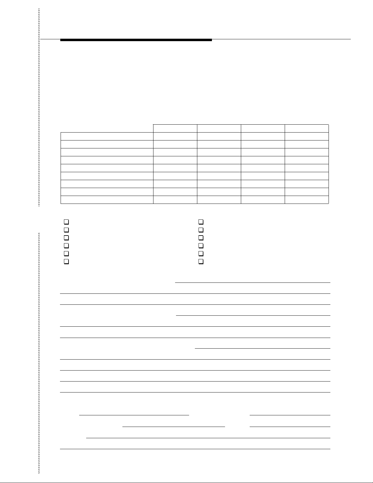
Lucent Technologies Wants Your Opinion
Lucent Technologies welcomes your feedback on this document. Your comments can be of great value in
helping us improve this document.
AUTOPLEX Cellular Telecommunications Systems System 1000 Series II Cell Site Description,
Operation, and Maintenance
1. Please rate the effectiveness of this document in the following areas:
Excellent Good Fair Poor
Ease of finding information
Clarity
Completeness
Accuracy
Organization
Appearance
Examples
Illustrations
Overall satisfaction
2. Please check the ways that you think this document could be improved:
Cut Here
Improve the preface/introduction. Make it more concise.
Improve the table of contents. Add more step-by-step procedures/tutorials.
Improve the organization. Add more troubleshooting information.
Include more illustrations. Make it less technical.
Add more examples. Add more or better quick reference aids.
Add more detail. Improve the index.
Please add details about your major concerns.
3. What do you like most about this document?
4. Write any comments below or on an attached sheet.
If we may contact you concerning your comments, please complete the following:
Name:
Company/Organization:
Address:
Telephone Number:
()
Date:
After completing this fo rm, please return it (postage-free) to the address on the reverse side. Thank you.
Page 5
10
Do Not Cut Fold Here And Tape
BUSINESS REPLY MAIL
FIRST CLASS PERMIT NO. 5 NEW PROVIDENCE N. J.
POSTAGE WILL BE PAID BY ADDRESSEE
Lucent Technologies
Customer Training and Information Products
1000 E. WARRENVILLE ROAD
IHC 1A-410
P.O. BOX 3013
NAPERVILLE, IL 60566-7013
NO POSTAGE
NECESSARY
IF MAILED
IN THE
UNITED STATES
Page 6

Contents
1 Introduction
Contents 1-1
■
Introduction 1-2
■
General 1-2
Organization 1-2
n
2 Introduction to Series II Cell Technology
Contents 2-1
■
Introduction 2-2
■
Overview 2-2
Advanced Mobile Phone Service (AMPS) 2-3
■
Time Divi si o n Mu lt ip le A cce s s (TDMA) 2-4
■
TDMA Description 2-4
TDMA Call Processing 2-4
Communication From TDMA Cell Site to TDMA Subscriber Unit2 -5
Communication From TDMA Subscriber Unit to TDMA Cell Site2-6
Code Division Multiple Access (CDMA) 2-6
CDMA Cell Site Description 2-7
Cellular Frequency Spectrum Allocation 2-10
■
Advantages of Series II Hardware and Software 2-11
■
Cell Site Equipment Functional Overview 2-12
■
Equipment Frames 2-12
Radio Channel Frames and Radio Equipment Functional Overview2-13
Facilities Interf ace Frame (FIF) 2-18
1-1
1-5
2-1
Lucent Technologies — Proprietary
See notice on first page
401-660-100 Issue 11 August 2000
v
Page 7

Contents
Figure 2-5.
3 Time Division Multi pl e Ac cess (TDMA)
Contents 3-1
■
TDMA Overview 3-3
■
TDMA/AMPS Dual-Mode Operation 3-3
TDMA System Access 3-4
TDMA Radio Interface 3- 4
Radio Channel Types 3-4
Digital Control Channel 3-5
Digital Control Channel (DCCH) Forward Link, or
Downlink, Logical Channels 3-5
DCCH Feature Offerings 3-6
Channel Organization for Forward DCCH Superframes3-6
Digital Traffic Channels 3-7
DTC Dedicated Control Channels 3-7
Digital Verification Color Code Channels 3-8
Handoff and Handoff Types 3-8
Mobile-Assisted Handoff Procedure 3-9
HandOff Based on Interference (HOBIT) / INt erference
■
Look-Ahead (INLA) Enhancement s3-11
Switch-Based TDMA Voice Coder/ Decoder (Vocoder) 3-15
■
Facilities Concentration 3-15
Cell Sites Supported by the Switch-Based Vocoder feature3-18
Operation, Administration, and Maintenance (OA&M) 3-19
Feature Activation and Install ati on 3-22
Separate Access Thresholds for DCCHs and DTCs (SEPA)3-23
■
Two-Branch Intelligent Anntenna (TBIA) 3-27
■
EDRU and DRM implementation of TBIA 3-27
2-19
3-1
vi
401-660-100 Issue 11 August 2000
Lucent Technologies — Proprietary
See notice on first page
Page 8

Contents
TBIA Performance 3-27
TBIA Availability 3-28
TBIA Activation 3-28
n
4 Code Division Multipl e Access (CDMA)
Contents 4-1
■
CDMA Overview 4-4
■
Transition to CDMA 4-4
CDMA Advantages Compared with AMPS and TDMA 4-5
Capacity 4-7
CDMA/AMPS Dual-Mode Operation 4-8
■
Lucent Technologies CDMA Architectur e 4-9
■
Hardware Requirements 4-9
Speech-Handling Equipment at the DCS 4-10
Call Setup 4-12
Radio Equipment 4-14
Cabinet Configurations 4-15
Radios and Radio Equipment 4-24
CRTU Components 4-31
CDMA Series II Configuration Options 4-34
Timing Requirements 4-35
New Features and Upgrades 4-40
■
Cell Site Synchronization Failure Warni ng &
Correction: Phase 1 4-40
New CDMA Cluster Controller (CCC) Board with
Increased SRAM 4 -40
Code Division Multiple Access (CDMA) Double Density Growth Frame (DDGF)4-42
■
3-29
4-1
Lucent Technologies — Proprietary
See notice on first page
401-660-100 Issue 11 August 2000
vii
Page 9

Contents
CDMA DDGF Description 4-42
DDGF Architecture 4-42
Using the DDGF in a Series II Analog Cell Site 4-47
RFTG 4-52
CDMA DDGF Power Requirements, Distribution, and Calibration4-55
Grounding Requirements 4-59
Connecting the DDGF to Frames in a Series II 4-63
CDMA Radio Test Unit Module and Interface 4-69
Alarms 4-73
n
5 Series II Cellular CDMA Adjunct to Sm all Cells
Contents 5-1
■
CDMA Adjunct 5-3
■
Overview 5-3
High Level Interface for the CDMA Adjunct 5-3
Supported Technologies 5-4
Traffic Capacity 5-5
RF Coverage Area 5-5
Physical Aspects of CDMA Adjunct 5-5
CDMA Adjunct Physical Positioning and External Equipment5-8
CDMA Adjunct to Host Cell Inter-frame Hardware Interfaces5-10
RF Distribution Paths 5-11
Radio Testing 5-16
Transmit Amplifiers 5-19
Input Voltage and Power 5-20
Environmental, Safety, and Handling Requirements 5-21
4-76
5-1
viii
401-660-100 Issue 11 August 2000
Lucent Technologies — Proprietary
See notice on first page
Page 10

Contents
UL and Cell Site A 5-23
Suggested DFI and DS-1 Configurations for use with the CDMA Adjunct5-24
Table 5-7.
6 Series II Cellular Digital Packet Data (CDPD)
Contents 6-1
■
CDPD Overview 6-3
■
Interfaces 6-3
Typical Configurations 6-6
Hardware 6-8
Detailed Diagrams of Supported Configurations 6-10
Grounding and Lightning Protection 6-23
Related Documentation 6-23
Table 6-2.
5-25
6-1
6-25
7 Mini, Micro, and Fiber-Link Series II Cell Site Options
Contents 7-1
■
General 7-2
■
Series IIe Cell Site 7-4
■
Compact Base Station (CBS) 7-6
■
CBS Documents 7-7
Series IIm T1/E1 MiniCell 7-8
■
Lucent Technologies — Proprietary
See notice on first page
401-660-100 Issue 11 August 2000
7-1
ix
Page 11

Contents
Installing the TRTU and DRU(s) 7-8
Installing the T-EDRU and EDRU(s) 7-8
Cabinet Descriptions 7-8
Series IIm T1/E1 Minicell Documentation 7-8
Series IImm T1/E1 MicroCell 7-9
■
AMPS/TDMA Mix with DRU Radios 7 -9
AMPS/TDMA Mix with EDRU Radios 7-10
Radio Self Power Upgade 7-10
Restoring Cell to Service 7 -12
f.
8 Series II Cell Site Equipment Desc ript ion s
Contents 8-1
■
General 8-4
■
Radio Channel Frame (RCF) Description 8-5
■
Series II Cell Site Radio Control Complex (RCC) Buses8-11
Series II Cell Site Radio Channel Unit Shelves ED-2R833-308-17
Radio Shelf Power Upgrade 8-20
Series II Cell Site Fan Panel Assembly
ED-2R824-31 8-28
Series II Cell Site Radio Test Unit Shelf 3
ED-2R835-30 8-29
Series II Cell Site Radio Channel Unit Shelves 4 and 5 ED-2R834-308-30
Series II Cell Site Interconnection Panel Assembly ED-2R831-308-31
Series II Cell Site Busbar Assembly Unit, KS24355, L18-39
Series II Mobile Switching Center (MSC) Int e rface 8-41
■
Series II Cell Site Linear Amplifi er Frame (LAF) 8-44
■
Series II Cell Site Linear Amplifier Circuit J41660CA-18-46
7-13
8-1
x
401-660-100 Issue 11 August 2000
Lucent Technologies — Proprietary
See notice on first page
Page 12

Contents
Series II Cell Site Linear Amplifier Module ED-2R840-308-52
Series II Cell Site Linear Amplifier Unit (LAU) 8-53
Series II Cell Site, 20-LAM LAC Versus 10-LAM LAC 8- 55
Series II Cell Site Linearizer Unit ED-2R841-30 8-56
Series II Cell Site Frame Interface Assembly ED-2R838-308-61
■
Series II Cell Site Antenna Interface Frame (AIF), Overview8-64
■
Series II Cell Site Reference Frequency Generator (RFG) Shelf8-69
Series II Cell Site Radio Switch Panel 8-76
Series II Cell Site Receive, Alarm, and Power Distribution Panel ED 2R851-30
8-76
Series II Cell Site Receive and Power Distribution Panel ED-2R853-318-77
Series II Cell Site Duplexer Filter Panel
ED-2R848-31 8-77
Series II Cell Site Receive Filter Panel
ED-2R846-31 8-78
Series II Cell Site Transmit Filter Panel ED-2R847-31 8-79
Series II Cell Site Equipment Summary 8-83
■
Series II Cell Site, Related Documentation 8-84
Table 8-16.
9 Radios
Contents 9-1
■
Introduction 9-3
■
AMPS Radio Units and Personality Types 9-4
■
TDMA Radio Units and Personality Types 9-8
■
8-86
9-1
Radio Channel Unit (RCU) 9-4
Radio Test Unit (RTU) 9-7
Digital Radio Unit (DRU) 9-8
Lucent Technologies — Proprietary
See notice on first page
401-660-100 Issue 11 August 2000
xi
Page 13

Contents
Enhanced Digital Radio Unit (EDRU) 9-8
Digital Radio Personality Types 9-8
DRU - Detailed Description 9-10
EDRU - Detailed Description 9-11
Series II Cell Site, Enhanced Digital Radio Unit (EDRU) Interfaces9-14
Enhanced Digital Radio Unit (EDRU) Reliabi lity, Feder al Communications Com-
mission (FCC), and Safety Features 9-16
Directional Setup and Beacon Channels 9-16
TDMA Radio Test Unit (TRTU) 9-17
Test Enhanced Digital Radio Unit (T-EDRU), Feature I Dentif ication (FI D) # 2775
9-18
CDMA Radio Maintenance Units and Personality Types 9-23
■
Pilot/Sync/Access Channel Element (CE) 9-24
Page CE 9-24
Traffic CE 9-24
Orthogonal-channel Noise Simulator CE 9-25
Figure 9-2.
10 Antenna Hardware Configurations
Contents 10-1
■
Introduction 10-3
■
Fixed Antenna Connection Configuration 10-5
3-Sector Directive Plus Omni Antenna Switching Configuration10-8
6-Sector Directive Plus Omni Antenna Switching with Dual-Radio Solution10-9
3- or 6-Sector Directional Antenna Switchi ng wit h Simul cast Setup10-9
All-Omnidirectional Configuration 10-9
All-Directional Configuration 10-10
Radio Transmission and Reception 10-13
■
Lucent Technologies — Proprietary
See notice on first page
9-26
10-1
xii
401-660-100 Issue 11 August 2000
Page 14

Contents
RF Transmitter Interfaces 10-13
R F R eceiver Interf ace s 10-14
2 Branch Intelligent Antenna, Featur e IDentification (FID) #314510-14
The Adaptive Interference Rejection Technique 10-15
0
11 Cell Site Hardware Functions and Interconnections
Contents 11-1
■
Introduction 11-5
■
Radio Control Complex (RCC) 11-5
Digital Signal (DS1) Units 11-6
Digital Facilities Int erface (DFI) Units 11-6
Clock And Tone (CAT) Units 11-7
Radio Frame Set 11-7
RCF Architecture and Bus Structure 11-9
Data Link and Voice
■
Path Connections1 1-14
T1/E1 Communications 11-14
Line Interface Connections at t he Cell 11-17
■
Data Link Configurations 11-21
■
One DS1/DFI Unit and One Data Link 11-21
One DS1/DFI Unit and Two Data Links 11-21
Two DS1/DFI Units and Two Data Links 11-21
Remote Data Link Reconfiguration 1 1-21
External Interfaces to the Series II Cell Site 11-22
■
Voice Trunks from the Digital Cellular Switch (DCS) 11-22
Time Division Multiplexed Buses 11-22
10-18
11-1
Lucent Technologies — Proprietary
See notice on first page
401-660-100 Issue 11 August 2000
xiii
Page 15

Contents
TDM Bus Communications: the Archangel/Angel Concept 11-26
■
Angel 11-27
Archangel 11-27
Sanity And Control Interface 11-28
■
NPE and SNPE 11-31
■
Synchronization of the Cell Site to the MSC 11-32
■
TDMCKSEL 11-36
TDMCKFAIL 11-36
TDMCLK 11-36
TDMFR 11-36
TDMSYNC1 11-36
TDMSYNC2 11-36
Mobile Switching Center (MSC) to Cell Site Communications11-37
■
DS1, DFI, and CAT Circuit Descriptions 11-38
■
DS1 (TN171) Circuit Description 11-38
DFI (TN3500) Circuit Description 11-38
DFI (TN1713B) Circuit Operation 11-40
DFI Initialization Message for T1 Operation 11-42
■
D 4 o r ES F F raming 11-42
DFI Initialization Message for E1 Operation 11-48
■
CEPT Framing with or without CRC-4 Error Checking 11-48
CCS or CAS Signaling Mode 11-48
HDB3 or Transparent Line Format 11-50
Enable or Disable On-demand LLB or BLB Control 11-50
Select Synchronization Reference 11-50
Select Idle Code 11-50
DFI Network-Update Talk Message 11-50
DFI Network-Update Listen Message 11-50
DFI Status Indicators 11-51
■
R ed LED 11-51
Yellow LED 11-51
Green LED 11- 51
xiv
401-660-100 Issue 11 August 2000
Lucent Technologies — Proprietary
See notice on first page
Page 16

Contents
CAT (TN170) Circuit Description 11-52
■
Bus Clock Generation and Monitoring for the TDM Bus 11-55
■
Maintenance Tone Generation 11-56
■
Maintenance Tone Detection and Measurement 11-57
CAT Status Indicators 11-58
■
R ed LED 11-58
Green LED 11- 58
Automatic Recovery Actions 11-59
■
Hardware Error Handling Strategy 11-60
■
Immediate Action 11-60
All Tests Pass (ATP) Analysis 11-60
Single Time-period Analysis 11- 60
Fail/Pass Analysis 1 1-60
Leaky Bucket Analysis 11 -61
RCC Hardware Errors and Recovery Actions 11-62
■
DS1/DFI Hardware Errors and Recovery Actions 11-63
■
DS1/DFI and T1 Errors—Detailed Description 11-64
■
Loss Of Signal (LOS) 11-64
Blue Alarm 11-64
R ed Ala rm 11-64
M ajor Alarm 11-65
Yellow Alarm 11-65
Fan Alarms 11-66
■
Preamp Fan 11-66
LineariZeR Fan Procedure 11-66
LAU Fan Procedure 11-67
Measuring the Linear Amplifier Unit (LAU) Fan Voltage11-67
DS1 E rro rs 11-68
■
Minor Alarm 11-68
Misframe Count 11-68
DFI and E1 Errors - Detailed Description 11-69
■
Loss Of Signal (LOS) 11-69
Lucent Technologies — Proprietary
See notice on first page
401-660-100 Issue 11 August 2000
xv
Page 17

Contents
Alarm Indication Signal (AIS) 11-69
Loss of Frame Alignment (LFA) 11-69
Loss of Multiframe Alignment (LMA) 11-70
10e-3 Error-ratio Alarm 11-70
Remote Frame Alarm (RFA) 11-70
Remote Multiframe Alarm (RMA) 1 1-71
10e-6 Error-Ratio Alarm 11-71
Slip Count 11-71
CAT Hardware Errors and Recovery Actions 11-72
■
Call-Processing Errors and Recover y Actions 11-72
12 Routine Maintenance and Radio Performance Tests
Contents 12-1
■
Maintenance Process 12-3
■
Maintenance Objective 12-3
Maintenance Activities 12-3
Preventive Maintenance 12-3
Routine Maintenance 12-3
Maintenance Assumptions 12-4
Routine Maintenance Procedures List 12-5
Fan Screen Cleaning 12-6
Radio Performance Testing 12-7
■
Radio Test Overview 12-7
Radio Pretest Procedure 12-7
Cable Loss Measurement 12-9
Power Measurement 12-12
Voice 1004 Hz Deviation Measurement 12-13
Post Test Procedure 12-15
Transmitter Output Power Verification 12-16
Transmitter Output Power Adjustment 12-16
12-1
xvi
401-660-100 Issue 11 August 2000
Lucent Technologies — Proprietary
See notice on first page
Page 18

Contents
Table 12-8.
13 Enhanced Maintenance Features
Contents 13-1
■
Improved Boot Read-Only Memory (ROM) / Non-Volatile Memory (NVM) Update
■
13-2
NVM Image for Single-Board RCU (SBRCU) 13-3
■
Keying Multiple RCU Transmitters 13-4
■
Opening Transmit and Receive Audio 13-5
■
Cell Site Power Measurements 13-6
■
Transmit and Receive Audio Level Measurements 13-7
■
Supervisory Audio and Signaling Tone Detecti on 13-8
■
Remote Data Link Reconfiguration 13-9
■
n
12-40
13-1
13-10
14 Corrective Maintenance - Introdu ction
Contents 14-1
■
Status Display Pages 14-2
ECP Craft Shell 14-2
Maintenance Request Administrator 14-3
Maintenance Units 14-4
■
AMPS Radio Maintenance Units and Personality Types14-6
TDMA Radio Maintenance Units and Personality Types14-7
CDMA Radio Maintenance Units and Personality Types14-9
Lucent Technologies — Proprietary
See notice on first page
14-1
401-660-100 Issue 11 August 2000
xvii
Page 19

Contents
Maintenance States 14-12
■
Maintenance states 14-12
Figure 14-3.
15 Corrective Maintenance usin g MRA
Contents 15-1
■
Maintenance Request Administrator (MRA) 15-2
■
Diagnose 15-3
■
Related Documents 15-4
Stop a Diagnostic 15-4
Obtain Status 15-4
Related Documents 15-4
Qualifiers Associated with the Out-Of-Service (OOS) State1 5-4
Dual Server Group Out-Of-Service (OOS) Limits 15-6
■
New RC/V Translation Parameters 15-6
Remove/Restore/Switch Actions 15-7
■
Conditional Remove 15-7
Unconditional Remove 15-11
Conditional and Unconditional Restore 15-13
Related Documents 15-16
Switch to a Redundant Unit 15-16
Related Documents 15-17
14-14
15-1
xviii
Lucent Technologies — Proprietary
See notice on first page
401-660-100 Issue 11 August 2000
Page 20

Contents
Figure 15-11.
16 Corrective Maintenance using Status Display Page s
Contents 16-1
■
Status Display Pages 16-3
■
2130 - Cell Site Status Summary Display Page 16-3
2131 - Cell Equipment Status Display Page 16-5
2131 - Removing Cell Site Units 16-9
2131 - Restoring Cell Site Units 16-11
2131 - Diagnosing Cell Equipment 16-12
2131 - Generating Cell Equipment Status Repor ts 1 6-14
2132 - Cell Software Status Display Page 16-15
2133 - Cell Voice Radio (VR) Status Display Page 16-18
2134 - Cell DS-1 Unit Status Display Page 16- 24
2134 - Removing/Restoring/Diagnos ing or
Generating a Status Report for DS1/DFI Units 16-26
2135 -Cell LC SU /BC Status Display Page 16-27
2135 - Removing/Restoring/ Diagnosing or Generating a Status Report for Lo-
cate or Setup Radios 16-31
2136 - Cell LAC Status Display Page 16-33
2137 - Cell OTU/LMT Status Display Page 16 -33
2138 - Cell CDMA Equipment
Status Display Page 16-36
2139 - Cell CCC CCU Status Display Page 16-42
2235 - Cell DCCH Status Display Page 16-48
2235 - Restoring/Diagnosing or Generating Status Reports for DCCH Radios
16-50
Dual Server Group Out-Of-Service (OOS) Limits 16-51
15-28
16-1
Lucent Technologies — Proprietary
See notice on first page
401-660-100 Issue 11 August 2000
xix
Page 21

Contents
17 Corrective Maintenance usin g ECP Craft In terfac e
Contents 17-1
■
ECP Craft Shell 17-3
■
Generating Cell Site Units/Radios/Alarms Status Reports17-3
Removing Cell Site Units 17-4
Restoring Cell Site Units 17-6
Diagnosing Cell Site Units 17-8
Stopping Cell Site Unit Diagnostics 17-10
Moving Cell Site Radios 17-11
Moving CDMA Calls to a Specified
Channel Element 17-12
Swapping CDMA Spectrum to/from
AMPS/TDMA 17-14
Generating Status Reports of Spectrum Swap of CDMA to/from AMPS/TDMA
17-15
Running Cell Site Audits 17-16
Diagnosing Cell Site Data Links 17-17
Stopping Cell Site Data Link Diagnostics 17-19
Diagnosing Cell Site Trunks Associated with a Se rver Group and Antenna Face
(Non-CDMA) 17-20
Stopping Diagnostics on Cell Site Trunks Associated with a Server Group and
Antenna Face 17- 21
Requesting Cell Site Data Link NVM Updates 17-22
Requesting Cell Site Hardware Unit NVM Updates 17-23
Initializ in g C e ll S it es 17-24
Initializing, Setting Up, and Using OCNS at CDMA Cell Sites17-26
Expansion of Maintenance Request Administ rator (MRA) and Technician Inter-
face Information Fields (MRAINFO/TI INFO), Feature IDentification (FID)
#3461.0 17-28
17-1
xx
401-660-100 Issue 11 August 2000
Lucent Technologies — Proprietary
See notice on first page
Page 22

Contents
n
18 Alarm Collection and Reportin g
Contents 18-1
■
Introduction 18-3
■
Equipment Alarms 18 -4
User-Defined Alarms 18-14
Increased Cell Alarms Enhancement 18- 16
■
New Hardware for the Increased Cell Alarms Enhancement18-17
New Translations for the Increased Cell Alarms Enhancement18-18
Directional Setup 18-18
Alarm Scanning Redesign 18-21
■
Introduction 18-21
Scope 18-22
C us tome r Perspecti ve 18-23
Features 18-23
Cell Site Functions 18-23
MSC Functions 18-24
CDMA Transmit Unit (CTU) and Receive Unit (RU) Separate Alarms18-27
Performance & Capacity 18-29
17-30
18-1
n
19 Cell Site Hardware LED Descriptions
Contents 19-1
■
Lucent Technologies — Proprietary
See notice on first page
18-30
19-1
401-660-100 Issue 11 August 2000
xxi
Page 23

Contents
LED Descriptions Table 19-2
■
Table 19-1.
19-10
20 AMapping Status Display Page Unit Numbers to Hardware
Contents 20-1
■
Introduction 20-2
■
Logical-to-Physical Mappings of Generic Cell Site Units20-2
Logical-to-Physical Mappings of CDMA-Specific Cell Site Units20-8
Figure 20-15.
21 CDMA Maintenance
Contents 21-1
■
Introduction 21-3
■
CRTU and CDMA Functional Testing 21- 3
CRTU Components 21-4
Subscriber and Feature Inform ati on Form 21 -8
Cell Equipage Component Location Form 21-9
2132 - Cell Software Status Display Page 21-10
Command and Report Changes to Support the CRTU 21-12
■
CRTU Growth Procedures 21-14
■
CDMA Functional Tests 21-15
Default Interval Values 21-17
20-20
21-1
20-1
xxii
401-660-100 Issue 11 August 2000
Lucent Technologies — Proprietary
See notice on first page
Page 24

Contents
Transmit and Receive Test Paths 21-17
MOST-Terminated Test Calls 21-18
Overhead Channel Functional Test 21-19
Functional Test Errors and System Recovery Acti ons 21-25
General Errors 21-25
Overhead Channel Functional Test Errors 21-25
n
22 Linear Amplifier Circuit (LAC) M aintenance
Contents 22-1
■
LAC Maintenance Procedures 22-3
■
LAC Alarm Summary: LACSUM 22-4
LAC Alarm Detailed Report: LACALM 22-5
Interpreting the LAC Alarm Reports 22-7
Troubleshooting Procedures at the Cell Site 22-13
LAM Alarm Procedures 22-15
Preamp Alarm Procedure 22-19
LAM Bias Fault Procedure 22-33
Fan Alarm Procedure 22-34
Linear Amplifier Circuit Removal/I nstallation Procedures22-59
Linear Amplifier Circuit Fans Removal/Installation Procedures22-69
21-29
22-1
21.
Lucent Technologies — Proprietary
See notice on first page
401-660-100 Issue 11 August 2000
22-90
xxiii
Page 25

Contents
xxiv
Lucent Technologies — Proprietary
See notice on first page
401-660-100 Issue 11 August 2000
Page 26

Figures
1 Introduction
n
2 Introduction to Series II Cell Technology
2-1 TDMA - DRU/ EDRU To/From Subscriber 2-6
2-2 CDMA System Components 2-8
2-3 Cell Site Architecture 2-13
2-4 Radio Channel Frames 2-14
2-5 Series II CDMA Radio Channel Frame (RCF) 2-17
Figure 2-5.
3 Time Division Multi pl e Ac cess (TDMA)
n
4 Code Division Multipl e Access (CDMA)
4-1 High-Level View of the Lucent Technologies CDMA Architecture4-9
Lucent Technologies — Proprietary
See notice on first page
401-660-100 Issue 11 August 2000
xxv
Page 27

Figures
4-2 Series II Cell Site Code Division Multiple Access (CDMA)
Communications Path4-13
4-3 CDMA Cell Site Equipment 4-16
4-4 Radio Frame Set Having Two CDMA Growth RCFs (TDMs install "red stripe up" )
4-18
4-5 Physical View of TDM Buses at the CDMA Series II Cell Site (TDMs install "red
stripe up") (Sheet 1 of 3)4-19
4-6 Physical View of TDM Buses at the CDMA Series II Cell Site (TDMs install "red
stripe up") (Sheet 2 of 3)4-20
4-7 Physical View of TDM Buses at the CDMA Series II Cell Site (TDMs install "red
stripe up") (Sheet 3 of 3)4-21
4-8 Fully Loaded CDMA Radio Shelf With BBA Redundancy4-22
4-9 CDMA Radio Architecture 4-28
4-10 High-Level View of the CRTU Test System 4-33
4-11 CDMA Subcell Configuration—BBA Interconnections Shown Only For One Side
(Side 1, Side 2)4-34
4-12 Reference Frequency and Timing Generator (RFTG)4-39
4-13 Quadrant and Half-shelf Numbering of DDGF (Front View)4-43
4-14 Illustration of Circuit Packs Populating the CRC 4-44
4-15 Configuration 3: AIF, LAF, and SII Primary, with DDGF as 1st CDMA Growth
Frame4-49
4-16 Configuration 4: AIF, LAF, SII Primary, SII CDMA Growth, with DDGF as 2nd
CDMA Growth Frame4-50
4-17 Configuration 5: AIF, LAF, SII Primary, SII Analog
(i.e., non-CDMA) Growth, with DDGF as 2nd Growth
Frame and 1st CDMA Growth Frame4-51
4-18 15-MHz Reference Frequency Distribution Scheme4-53
4-19 Reference Frequency and Timing Generator (RFTG)4-54
4-20 Double Density Growth Frame (top panel removed to expose ci rcuit breakers -
Rear View)4-60
4-21 Frame Ground From Adjacent Cabinet 4-61
4-22 Ground Wire Connections Between Frames 4-62
4-23 DDGF IPA 4-64
4-24 Top of LAF 0, MLAC Power Divider Inputs 4-65
4-25 Top of LAF 1, MLAC Power Divider Input 4-66
xxvi
Lucent Technologies — Proprietary
See notice on first page
401-660-100 Issue 11 August 2000
Page 28

Figures
4-26 Top of AIF 0, RX 0, and RX 1 Power Divider Outputs (front view)4-67
4-27 Top of AIF 1, RX 0, and RX 1 Power Divider Outputs4-68
4-28 TDM Bus I nstal lati on. TDM bus cabl es are i nstall ed "red s trip e up." (Conf igura tion
3)4-70
4-29 TDM Bus Installation . TDM bus cables are i nstalled "red s tripe up." (Conf igurations
4 and 5)4-71
4-30 CDMA Radio Test Unit Module 4-72
n
5 Series II Cellular CDMA Adjunct to Sm all Cells
5-1 CDMA Adjunct Frame External Interfaces 5-4
5-2 CDMA Adjunct Frame 5-6
5-3 CDMA Adjunct Frame LineUp 5-8
5-4 CDMA Adjunct Antenna Connections 5-10
5-5 CDMA Adjunct Frame External Interfaces 5-11
5-6 CDMA Adjunct/Host Cell Transmit Path 5-12
5-7 Series IImm (Microcell)/CDMA Adjunct Transmit (Tx) Path Using Series IImm
(Microce ll) Amplifie r5 - 1 4
5-8 CDMA Adjunct/Host Cell Receive Paths 5-15
5-9 Test Radio Switch Panel (TRSP) 5-18
5-10 CDMA Adjunct Receiver Paths 5-20
5-11 CDMA Transmit Path (Smm Only) 5-21
Lucent Technologies — Proprietary
See notice on first page
401-660-100 Issue 11 August 2000
xxvii
Page 29

Figures
Table 5-7.
6 Series II Cellular Digital Packet Data (CDPD)
6-1 Series II CDPD Connections 6-3
6-2 One CDPD Channel per Sector 6-6
6-3 Two to Four CDPD Channels per Sector 6-7
6-4 CDPD with Omni Setup 6-8
6-5 Functional Diagram 6-10
6-6 One Modem Transceiver Per Sector, One LAC per Sector -
Directional Setup6-12
6-7 One Modem Transceiver per Sector, Multiple LACs per Sector -
Sniffing on One LAC - Directional Setup6-13
6-8 One Modem Transceiver per Sector, Multiple LACs per Sector -
Sniffing on Multiple LACs - Directional Setup6-14
6-9 One Modem Transceiver per Sector, One LAC per Sector -
Omnidirectional Setup6-15
6-10 One Modem Transceiver per Sector, Multiple LACs per Sector -
Sniffing on One LAC - Omnidirectional Setup6-16
6-11 One Modem Transceiver per Sector, Multiple LACs per Sector -
Sniffing on Multiple LACs - Omnidirectional Setup6-17
6-12 Multiple Modem Transceiver per Sect or, One LAC per Sector -
Directional Setup6-18
6-13 Mul tiple Modem Transceiver per Sector, Multiple LACs per Sector - Sniffi ng on One
LAC - Directional Setup6-19
6-14 Multiple Modem Transceiver per Sector, Multiple LACs per Sector - Sniffing on
Multiple LACs - Directional Setup6-20
6-15 Multiple Modem Transceiver per Sector, One LAC per Sector - Omnidirectional
Setup6-21
6-16 Mul tiple Modem Transceiver per Sector, Multiple LACs per Sector - Sniffi ng on One
LAC - Omnidirectional Setup6-22
6-17 Multiple Modem Transceiver per Sector, Multiple LACs per Sector - Sniffing on
Multiple LACs - Omnidirectional Setup6-23
xxviii
Lucent Technologies — Proprietary
See notice on first page
401-660-100 Issue 11 August 2000
Page 30

Figures
Table 6-2.
7 Mini, Micro, and Fiber-Link Series II Cell Site Options
7-1 Series IIe Radio Frame Set 7-5
7-2 Series II Compact Base Station (CBS) Hardware Architecture7-7
f.
8 Series II Cell Site Equipment Desc ript ion s
8-1 Primary Radio Channel Frame J41660A-2 8-6
8-2 Growth Radio Channel Frame (J41660B-2) 8-7
8-3 Radio Control Complex (RCC) - Shelf 0 ED-2R832-308-14
8-4 Radio Channel Unit - Shelf 1, Shelf 2 ED-2R833-30 (Figur e 1 of 2)8-18
8-5 Radio Channel Unit (Rear View) - Shelf 1, Shelf 2 ED-2R833-30 (Figure 2 of 2)
8-19
8-6 Fan Panel Assembly ED-2R824-31 8-28
8-7 Radio Test Unit (RTU) - Shelf 3 ED-2R835-30 8-29
8-8 Radio Channel Unit - Shelf 4, Shelf 5 ED-2R834-308-30
8-9 Radio Channel Unit (Rear View) - Shelf 4, Shelf 5 ED-2R834-308-31
8-10 Interconnection Panel ED-2R831-30 8-32
8-11 Interconnection Panel ED-2R831-30 8-33
8-12 Radi o Test Unit (RTU) Control Board (AYD8) and Switch Asse mbly (ED3R026-30)
Location8-42
8-13 Linear Amplifier Frame (LAF) (J41660C-1) 8-45
8-14 Linear Amplifier Frame (LAF) (Doors Removed) 8-46
8-15 Linear Amplifier Circuit (LAC), Front View 8-48
Lucent Technologies — Proprietary
See notice on first page
401-660-100 Issue 11 August 2000
xxix
Page 31

Figures
8-16 LAC Functional Diagram 8-50
8-17 Linear Amplifier Module (LAM) 8-53
8-18 Linear Amplifier Unit ED-2R839-30 8-54
8-19 Location of LAM Fuses, LEDs, and the 10/20 Switch (on C-Series LACs)8-55
8-20 Linearizer (LZR) Unit ED-2R841-30 8-57
8-21 Linearizer Unit ED-2R841-30 8-58
8-22 Linearizer Unit ED-2R841-30 8-59
8-23 Linearizer Faceplate with the Fr ont Gri lle Removed 8-60
8-24 Frame Interface Assembly ED-2R838-30 8-62
8-25 Frame Interface Assembly ED-2R838-30 8-63
8-26 Antenna Interface Frame (AIF) Functional Diagram8-64
8-27 Antenna Interface Frame (AIF) Functional Architecture8-65
8-28 Antenna Interface Frame (AIF) Functional Diagram 8-66
8-29 Antenna Interface Frame (AIF) Functional Diagram 8-67
8-30 Antenna Interface Growth Frame (AIF) Functional Diagram8-68
8-31 Primary Antenna Interface Frame (AIF) J41660E-2 8-72
8-32 Primary Antenna Interface Frame J41660E-2 8-73
8-33 Growth Antenna Interface Frame J41660F -2 8-74
8-34 Growth Antenna Interface Frame J41660F-2 8-75
Table 8-16.
9 Radios
9-1 AMPS Radio Maintenance Units and Personality Types9-4
9-2 CDMA Radio Maintenance Units and Personality Types9- 24
xxx
401-660-100 Issue 11 August 2000
Lucent Technologies — Proprietary
See notice on first page
Page 32

Figures
Figure 9-2.
10 Antenna Hardware Configurations
10-1 Series II Cell Site Antenna Configurations 10-4
10-2 Interconnection Panel Assembly 10-6
10-3 Antenna Interface 10-7
10-4 Primary RCF Switch Antenna Connector 10-8
10-5 Mapping of Antenna Faces to Antenna Sets for the
Various Setup Options10-10
10-6 Omnidirectional Cell Site Having Seven Tra nsmit Antennas10-11
10-7 Antenna Coupler 10-14
0
11 Cell Site Hardware Functions and Interconnections
11-1 Series II Cell Site Architecture 11-5
11-2 Radio Frame Set Architecture and Bus Structure 11-7
11-3 Physical View of TDM Buses (Sheet 1 of 3) 11-10
11-4 Physical View of TDM Buses (Sheet 2 of 3) 11-11
11-5 Physical View of TDM Buses (Sheet 3 of 3) 11-12
11-6 Data Link and Voice Paths—Example 11-15
11-7 T1/DS1 Transmission Format and RCF TDM Bus Transmission Format11-18
11-8 E1/CEPT Transmission Format and RCF TDM Bus Transmission Format11-19
11-9 TDM-Bus Interface Circuitry for the NCI—TDM Bus Archangel11-23
11-10 TDM-Bus Interface Circuitry for the CPI—TDM Bus Angel11-26
11-11 SAKI and SNPE Interface 11-29
Lucent Technologies — Proprietary
See notice on first page
401-660-100 Issue 11 August 2000
xxxi
Page 33

Figures
11-12 Synchronization References for TDM0 and TDM1—Example11-33
11-13 Synchronization of TDM0 to the MSC 11-35
11-14 Primary Access Controller/Framer 11-40
11-15 Information Sheets for T1 D4 and ESF Framing Format
(Sheet 1 of 3)11-43
11-16 Information Sheets for T1 D4 and ESF Framing Format
(Sheet 2 of 3)11-44
11-17 Information Sheets for T1 D4 and ESF Framing Format
(Sheet 3 of 3)11-45
11-18 Information Sheets for CCITT CEPT Frame Format
With and Without CRC-411-49
11-19 CAT Block Diagram (Sheet 1 of 2) 11-53
11-20 CAT Block Diagram (Sheet 2 of 2) 11-54
12 Routine Maintenance and Radio Performance Tests
12-1 Voice Channel Test Paths 12-8
12-2 Voice Channel Test Paths 12-9
xxxii
Lucent Technologies — Proprietary
See notice on first page
401-660-100 Issue 11 August 2000
Page 34

Figures
Table 12-8.
13 Enhanced Maintenance Features
n
14 Corrective Maintenance - Introdu ction
14-1 AMPS Radio Main tenance Units and Personality Type14-7
14-2 TDMA Radio Mai ntenance Units and Personality Types1 4-9
14-3 CDMA Radio Maintenance Units and Personality Types14-11
Figure 14-3.
15 Corrective Maintenance usin g MRA
15-1 Remove Flow of Voice Radio RCU, SBRCU, DRU, or EDRU (Sheet 1 of 3)15-17
15-2 Remove Flow of Voice Radio RCU, SBRCU, DRU, or EDRU (Sheet 1 of 3)15-18
15-3 Remove Fl ow of Voice Radio RCU, SBRCU, DRU, or EDRU (Sheet 3 of
3)15-19
15-4 Remove Flow of CCC (Sheet 1 of 3) 15-20
15-5 Remove Flow of CCC (Sheet 2 of 3) 15-21
15-6 Remove Flow of CCC (Sheet 3 of 3) 15-22
15-7 Remove Flow of CCU (Sheet 1 of 3) 15-23
Lucent Technologies — Proprietary
See notice on first page
401-660-100 Issue 11 August 2000
xxxiii
Page 35

Figures
15-8 Remove Flow of CCU (Sheet 2 of 3) 15-24
15-9 Remove Flow of CCU (Sheet 3 of 3) 15-25
15-10 Remove Flow of BBA (Sheet 1 of 3) 15-26
15-11 Remove Flow of BBA (Sheet 2 of 3) 15-27
Figure 15-11.
16 Corrective Maintenance using Status Display Page s
16-1 Example of 2130 - Cell Site Status Summary Page 16-4
16-2 Example of 2131 - Series II Cell Site Equipment Status Page16-6
16-3 Example of 2132 - Series II Cell Site Software Status Page
- ECP Release 9.016-16
16-4 Computer Terminal Screen: 2133 - Series II Cel l VR Status Page16-21
16-5 Example of 2134 - Series II Cell Site DS-1 Unit Status Page16-25
16-6 Example of 2135 - Series II Cell Site LC/SU/BC Status Page
(Locate Radio Version)16-29
16-7 Example of 2135 - Series II Cell Site LC/SU/BC Status Page
Setup Radio Version)16-30
16-8 Example of 2136 - Series II Cell Site LAC Status Display Page16-33
16-9 Example of 2137 - Series II Cell Site OTU/LMT Status Page16-35
16-10 Example of 2138 - Series II Cell Site CDMA Equipment Status Page16-38
16-11 Example of 2139 - Series II Cell Site CCC CCU Status Page16-44
16-12 Example of 2235 - Series II Cell Site DCCH Status Page16-49
xxxiv
Lucent Technologies — Proprietary
See notice on first page
401-660-100 Issue 11 August 2000
Page 36

Figures
17 Corrective Maintenance usin g ECP Craft In terfac e
n
18 Alarm Collection and Reportin g
18-1 Alarm Cabling in the Primary RCF 18-4
18-2 AFI Block Diagram 18-7
18-3 RCG, Receive Preamplifier, and RFG Alarm Devices18-8
18-4 Alarm Monitoring and Storage in the Primary RCF (Sheet 1 of 2)18-9
18-5 Alarm Monitoring and Storage in the Primary RCF (Sheet 2 of 2)18-10
18-6 Alarm Connections Via the AAI J2 Ribbon-Type Connector18-11
18-7 Alarm Connections Via the AAI J3, J4, and J5 Terminal Blocks18-12
18-8 Radio Channel Frame (RCF) Receiver Radio Frequency (RF) I nterfaces
(Switchable Antenna Connection)18-20
Lucent Technologies — Proprietary
See notice on first page
401-660-100 Issue 11 August 2000
xxxv
Page 37

Figures
n
19 Cell Site Hardware LED Descriptions
Table 19-1.
20 AMapping Status Display Page Unit Numbers to Hardware
20-1 Logical-to-Physical Unit Mapping for the RCC, DS1, and CAT in
Primary RCF20-4
20-2 Logical-to-Physica l Uni t Mapping for the DS1 20-5
20-3 Logical-to-Physica l Uni t Mapping for the CAT (Sheet 1 of 3)20-6
20-4 Logical-to-Physica l Uni t Mapping for the CAT (Sheet 2 of 3)20-7
20-5 Logical-to-Physica l Uni t Mapping for the CAT (Sheet 3 of 3)20-8
20-6 Logical-to-Physical Unit Mappin g for the CCC (Sheet 1 of 2)20-10
20-7 Logical-to-Physical Unit Mappin g for the CCC (Sheet 2 of 2)20-11
20-8 Logical-to-Physical Unit Mappin g for the BBA (Sheet 1 of 2)20-12
20-9 Logical-to-Physical Unit Mappin g for the BBA (Sheet 2 of 2)20-13
20-10 Logical-to-Physical Unit Mapping for the DFI/DS1 and SCT/CAT
(Sheet 1 of 6)20-14
20-11 Logical-to-Physical Unit Mapping for the DFI/DS1 and SCT/CAT
(Sheet 2 of 6)20-15
20-12 Logical-to-Physical Unit Mapping for the DFI/DS1 and SCT/CAT
(Sheet 3 of 6)20-16
20-13 Logical-to-Physical Unit Mapping for the DFI/DS1 and SCT/CAT
(Sheet 4 of 6)20-17
20-14 Logical-to-Physical Unit Mapping for the DFI/DS1 and SCT/CAT
(Sheet 5 of 6)20-18
xxxvi
Lucent Technologies — Proprietary
See notice on first page
401-660-100 Issue 11 August 2000
Page 38

Figures
20-15 Logical-to-Physical Unit Mapping for the DFI/DS1 and SCT/CAT) (Sheet 6 of 6)
20-19
Figure 20-15.
21 CDMA Maintenance
21-1 High-Level View of the CRTU Test System 21-4
21-2 RF Transmit Path Setup for CDMA Functional Tests at
the Series II Cell Site21-6
21-3 RF Diversity 0 Receive Path Setup for CDMA Functional Tests at
the Series II Cell Site21-18
n
22 Linear Amplifier Circuit (LAC) M aintenance
22-1 Front View of the LAC 22-10
22-2 LAMs Powered by Common Breakers 22-18
22-3 Location of LAM Fuses, LEDs, and the 10/20 Switch (on C-Series LACs)22-19
22-4 Flowchart of the Preamplifier Diagnostic Procedure22-21
22-5 Setting the LAC Address 22-23
22-6 Location of the Alarm Cable Connector at Top of the RCF22-28
22-7 Location of the AYD5 Paddle Board on the RCC Backplane22-30
22-8 UN166 AFI Board Test Points 22-31
22-9 Location of the LAC Alarm Cable Connector 22-32
22-10 Location of the FAC/FLD Switch and Microprocessor Access Port (Cover
Removed)22-33
Lucent Technologies — Proprietary
See notice on first page
401-660-100 Issue 11 August 2000
xxxvii
Page 39

Figures
22-11 View of the Linearizer Faceplate with the Front Grille Removed22-35
22-12 Measuring the LAU Fan Voltage 22-37
22-13 Location of AYG3 Circuit Pack Fuses F7 and F8 (Cover Plate Removed)22-42
22-14 Linear Amplifier Circuit (LAC), Front View 22-44
22-15 Linear Amplifier Frame (LAF) (Doors Removed) 22-67
22-16 Linear Amplifier Unit 22-68
22-17 LAM 22-71
22-18 Disconnect the ribbon cable from the printed circui t boar d (donut)22-72
22-19 Unscrew the LAM from its standoff 22-73
22-20 RF connectors on each LAM 22-74
22-21 Disconnect the remaining ribbon connectors from the donut board22-75
22-22 Remove the printed circuit board (donut) from the standoffs22-7 6
22-23 Disconnect D-Shell connector located behind the donut board22-77
22-24 Push the printed donut board to the right side 22-78
22-25 Remove and save silver standoffs and washers 22-79
22-26 Cut the three cables (black, red, blue) to each fan 22-81
22-27 Remove both fans 22-82
22-28 Identify LAC where the malfunctioning linearizer fan resi des22-84
22-29 Linearizer fan fuse 22-85
22-30 Linearizer faceplate 22-86
22-31 Fan Mounting Plate 22-87
22-32 Cabling by Color (Red To Red, Black To Black, Blue To Blue)22-89
xxxviii
21.
Lucent Technologies — Proprietary
See notice on first page
401-660-100 Issue 11 August 2000
Page 40

Introduction
Contents
Contents 1-1
■
Introduction 1-2
■
General 1-2
Organization 1-2
1
Lucent Technologies — Propriet ary
See notice on first page
401-660-100 Issue 11 August 2000
1-1
Page 41

Introduction
Introduction
General
Organization
This document has been made current to Executive Cel lul ar Processor (ECP)
Release 14.0.
The contents of each chapter in this document are descri bed in t he following list.
Chapter 2 introduces the user to the Cell Site architecture and its
■
interaction with other parts of the system, the availabil ity and use of
bandwidth, the call handling process, and the advantages of Series II
hardware and software.
Chapter 3 is a detailed look as the Time Division Multiple Access (TDMA)
■
system, so that the ne w-hire, manager, or engineer obtains an in-depth
understanding of TDMA technolog y and why, when, wher e, and how to
implement it.
Chapter 4 is a detailed look as the Code Division Multiple Acces s (CDMA)
■
system, so that, again, the ne w-hire, manager, or engineer obtains an indepth understanding of CDMA technolog y and why, when, where, and how
to implement it.
Chapter 5 introduces a new product, the CDMA Adjunct to Small Cells,
■
which is used to add CDMA capability to the Series IIm (Minicell) and
Series IImm (Microcell).
Chapter 6 covers the Cellular Digital P acket Data (CDPD) service, which
■
enables the service provider to offer wireless data services. Se ve r al CDPD
configurations are offered in this chapter.
Chapter 7 cove rs other technology options available for the Series II
■
system. Including the use of fi beroptics and the subdivisi on of cellular
systems into mini or micro systems for situations such as filling in spots
missed by the large r cellul ar system or for the use of cellular syst ems withi n
a restricted environment, such as an office building.
For those that need equipment specifications for Cell Site engineering, to order
equipment, or to obt ain a gen eral k nowled ge o f the hardw are us ed in the Series I I
Cell Site, the following chapters offer a general look at every piece of hardware
used at the Cell Site.
Chapter 8 describes and offers equipment specifications, ordering codes,
■
and interconnections with othe r equipment, for every piece of hardware
(except radios) at the Cell Site.
Chapter 9 contains detailed t echnical descript ions of e very radi o capabl e of
■
being used in the Cell Site, how each radio operates, and its call-handling
capacity. All radios, AMPS, TDMA, and CDMA, are explai ned.
Chapter 10 describes antenna co nfigur ati ons and the ir in tera ction wi th Cell
■
Site radios.
Lucent Technologies — Propriet ary
See notice on first page
1-2
401-660-100 Issue 11 August 2000
Page 42

Introduction
Chapter 11 describes Cell Site hardware at a functional level, the
■
interconnections on each unit, and their interconnectivity with other units.
For operations and maintenance personnel, the following chapters describe the
function and operation of all Series II equipment, and different aspects of its
maintenance (i.e ., test, restore, remove, replace).
Chapter 12 offers detailed and step-by-step procedures to perform routine
■
and FCC-mandated maintenance tests.
Chapter 13 describes enhanced maintenance features that have been
■
added to the Series II Cell Site, such as the improved Boot Read-OnlyMemory / Non-Volat ile Memory Update. This feature enables a radio to
identify its hardware type and prevent the downloading of firmware
belonging to a different radio hardware type.
Chapter 14 explain s the three major maintenanc e tools av aila ble to the Cell
■
Site Technician, describes and lists all maintenance units, and defines the
maintenance states that a unit can take on.
Chapter 15 has detailed and step-b y-step procedures for using the
■
Maintenance Request Administrator (MRA) to perform diagnostic and
trouble maintenance.
Chapter 16 has detailed and step-by-step procedures for using Status
■
Display Pages to perform diagnostic and trouble maintenance.
Chapter 17 has detailed and step-b y-step procedures for using the
■
Executive Cellular Processor (ECP) craft interface to perform diagnostic
and trouble maintenance.
The different tools and procedures described in the chapters above allow the
technician to choose the maintena nce tool he is most comfortable with and,
greatly impro ve both the learning and productivity curve.
Chapter 18 details all Cell Site alarms, their meaning, and the appropriate
■
response(s) the technician should make.
Chapter 19 details all Cell Site Light Emitting Diodes (LEDs), their
■
meaning, and the appropriate response(s) the technician should make.
Chapter 20 is a logical-to-hardware mapping of all maintenance units and
■
is useful in helping the technician fi nd the physical location of any
diagnostic or maintenance unit.
Chapter 21 is dedicated to CDMA-specific maintenance because CDMA
■
units are differ ent enough from the analog/digital units used in AMPS/
TDMA that they merit particular attention.
Chapter 22 is dedicated to the maintenance of the Linear Amplif ier Circuit
■
(LAC), a complex and extremely important piece of Cell Site hardware .
Lucent Technologies — Propriet ary
See notice on first page
401-660-100 Issue 11 August 2000
1-3
Page 43

Introduction
Please refer to Lucent Technologies Practice 401-660-125 for a full description of
the Modular Linear Amplifier Cir cuit (MLAC) J-41660CA- 3.
We hope that y ou fi nd this reorganization of the document useful and easy to
read.
1-4
401-660-100 Issue 11 August 2000
Lucent Technologies — Propriet ary
See notice on first page
Page 44

Lucent Technologies — Propriet ary
See notice on first page
401-660-100 Issue 11 August 2000
1-5
Page 45

1-6
401-660-100 Issue 11 August 2000
Lucent Technologies — Propriet ary
See notice on first page
Page 46

Introduction to Series II Cell
Techno logy
Contents
Contents 2-1
■
Introduction 2-2
■
Overview 2-2
Advanced Mobile Phone Service (AMPS) 2-3
■
Time Division Multiple Access (TDMA) 2-4
■
TDMA Description 2-4
TDMA Call Processing 2-4
Communication F rom TDMA Cell Site to TDMA Subscriber Unit 2-5
Communication F rom TDMA Subscriber Unit to
TDMA Cell Site 2-6
Code Division Multiple Access (CDMA) 2-6
CDMA Cell Site Description 2-7
Cellular Frequency Spectrum Allocation 2-10
■
Advantages of Series II Hardware and Software 2-11
■
Cell Site Equipment Functional Overview 2-12
■
Equipment Fr ames 2-12
Radio Channel Frames and
Radio Equipment Functional Overview 2-13
Facilities Interface F rame (FIF) 2-18
2
Lucent Technologies — Propriet ary
See notice on first page
401-660-100 Issue 11 August 2000
2-1
Page 47

Introduction to Series II Cell Technology
Introduction
Overview
The Series II platform accommodates t hree m ulti ple-acc ess metho ds, one ana log
and two digital, described below.
■
Frequency Division Multiple Access (FDMA) -
Subscribers are separated by frequency. Frequency Div isi on Multiple
Access (FDMA) is the implementation of narrowband channels, each
carrying one telephone circuit, in a system where any mobile station can
access any one of the frequencies. Existing analog cellular
communications systems use FDMA.
The Series II FDMA technology is Advanced Mobile Phone Service
(AMPS)* which conforms to the Electronic Indust ries Assoc iation (EIA) /
Telecommunications Industry Association (TIA) 553 standard. The
allocated spectrum is divided into 30-kHz channels, where each channel
can carry a single call.
■
Time Division Multiple Access (TDMA) -
Subscribers are separated b y fr equency and time. Time Division Multipl e
Access (TDMA) is an architecture in which each carrier frequency is
divided into a number of timeslots, each of which constitutes an
independent telephone circuit. Existing digital cellular communications
systems use TDMA.
The Series II TDMA technology conforms to the TIA IS-54 standard. The
technology can serve t hree simultaneous calls on an existing 30-kHz
AMPS channel, thereby increasing capacity by threefold.
■
Code Division Multiple Access (CDMA) -
Subscribers are separated by digital code. Code Division Multiple Access
(CDMA) is a form of multiple access used in spread- spectrum wideband
systems. It is based on the principle that e ach subscriber is assigned a
unique code that can be used b y the syste m to distingu ish that user from al l
other users transmitting simultaneously over the same frequency band.
The Series II CDMA technology conforms to the TIA IS-95 standard. The
projection is that CDMA will increase the capacity of the current AMPS
system by as much as ten-fold.
* Throughout this document, AMPS will be used to mean analog radios or analog service.
Lucent Technologies — Propriet ary
See notice on first page
2-2
401-660-100 Issue 11 August 2000
Page 48

Introduction to Series II Cell Technology
Advanced Mobile Phone Service
(AMPS)
With AMPS, the entire alloc ated cellular frequency spectrum, 825-890 MHz, is
divided into a number of 30-kHz cha nnel s, eac h with its speci fic carrier frequency.
These carrier frequencies operate in pairs; each pair is assigned a unique RF
channel number. One carrier frequency of the pair is used for transmission from
the Cell Site to the mobile station (forward channel), while the other is used for
transmission from the mobile st ati on to the Cell Site (reverse channel). The
transmit and receive frequencies are sepa rated by 45 MHz.
Fr om the begi nning, the FCC has encouraged competition in the cell ular radio
market by alloca ting avai lable frequency spectrum to two classes of operators:
The nonwireline companies (such as radio common carriers) also known
■
as System A - is allocated frequencies from spectrum for System A is
(known as block A, which consists of the A, A’, and A” bands
The local wireline telephone companies, also known as System B - is
■
allocated frequencies from the spect rum f or System B (known as block B),
which consists of the B and B’ bands.
Normally, RF channels 313 through 354 are reserved for use as control channel s:
21 control channels for System A, and 21 control channels for System B. These
channels, also called setup channels, are used to establish calls and to perform
control functions. The remaining channels, 395 for System A and 395 for
System B, are the voic e channel s. Each voice channel can carry a single call.
Lucent Technologies — Propriet ary
See notice on first page
401-660-100 Issue 11 August 2000
2-3
Page 49

Introduction to Series II Cell Technology
Time Division Multiple Access
(TDMA)
TDMA
Description
TDMA Call
Processing
TDMA can accommodate both analog and digital cellular technologies (see
Figure 2-1). The digital cellular technology, like Time Divisi on Mult iple Access
(TDMA) radio technology, provides increased spectral efficiency, system
performance improvements (high-quality speech in areas of low signal strength),
entirely digital tr ansmission, new and more flexible services, and i ncreased
channel privacy compar ed to analog technology. In the same number of radio
slots used by Radio Channel Unit s (RCUs), half as many Digital Radio Units
(DRUs) achieve a 50% increase in the number of radio channels. In addi ti on, if
DRUs ar e repla ced with Enhanc ed DRUs (EDRUs), there are th e same n umber of
channels using half as many radio slots on the radio shelf. The EDRU takes up
only 1 slot on the radio shelf versus the 2 that the DRU t akes up.
The Telecommunications Industry Association (TIA) has prepared an interim
standard (IS-54A) that defines technical requirements for cellular
telecommunications systems. This standard provi des radio system parameters
and call processing procedures for both analog and digital radios to ensure
complete compatibility with dual-mode (analog and digital) mobile and singl emode (analog only) mobile stations. The TDMA feature complies with this
standard.
In addition, TDMA DCCH complies with EIA/TIA Stand ard IS-136 Cellular Sy stem
Dual-Mode Mobile Station Base Station: Digital Control Channel that is av ail able
from the Electronic Industries Association. DCCH supports IS-136 mobiles that
use DCCH to access the system.
The following call processing features are part of the TDMA feature .
Dual Mode Mobile Station (DMMS) - TDMA works with a DMMS. The
■
TDMA DMMS has allowable-c all modes of analog only, TDMA (digital) only,
and analog or TDMA. TDMA also supports IS-136 mobiles that acc ess the
system over the DCCH.
Mobile-Assisted HandOff (MAHO) Feature - All TDMA mobile units are
■
designated to assist in the handoff process. The TDMA mobile unit is sent
a list of neighbor sector s on which to make signal strength measurements.
Setup Channels - TDMA uses the same analog setup channels as in the
■
Series II Cell Site. To set up digital channels, TDMA uses the DCCH.
Locate Function - The locate radios may be analog. TDMA also supports
■
the digital locate function for DR Us and EDRUs.
Beacon Channel Feature - The beacon channel is a voice radio, analog or
■
digital, which always has its carrier turned on and set at a f ixed power leve l.
The beacon channel can be used for voice communications , but t he carrier
Lucent Technologies — Propriet ary
See notice on first page
2-4
401-660-100 Issue 11 August 2000
Page 50

Introduction to Series II Cell Technology
power level remains fixed. The beacon channel provides a means for the
TDMA and TDMA DMMS mobiles to measure signal strength during the
handoff process. Series I Cell Sites in a Series II TDMA service area also
provide a beacon channel per antenna sector for the benefit of TDMA
customers.
Unique software is requi red for implementation of the TDMA feature. This section
briefly addresses t he major differences from the analog system in call process ing ,
administration, maintenance, and service measurement software.
All call processing for DRUs is based on logical channels; that is, di git al traffic
channels rather than physic al radio units . The DMMSs communicate with the Cell
Site over a 30-kHz analog setup channel. Thus, the mobile station is required to
be tuned to an analog setup channel when not in the conversation state. Mobile
originations and page response messages are transmitted to and received from
the Cell Site over the analog setup channel. Location measurements on digital
voice channels will be performed using mobile-assisted handoff (as defined in IS54A).
The following five handoff scenarios are supported:
1. Analog to analog
Communication
From TDMA Cell
Site to T DMA
Subscriber Unit
2. Analog to digital
3. Digital to digital
4. Digital to analog
5. DCCH InterHyperband handoff
For more information on DCCH InterHyperband Handoff, please see Lucent
Technologies Practices Optional Feature document 401-612-118, DCCH
Interhyperband Operation Phase 1 & 2.
The Time Division Multiplexed (TDM) bus, which should be installed "red stripe
up," sends m-law Pulse Code Modulation (PCM) encoded voice to the echo
cancelers, and then to the speech coder in the DRU or EDRU. The speech from
the TDM bus is coded using the algorithm know n as Code Excit ed Linear
Predictive ( CELP) Codin g. Then t he bit s are t r ansferred to the associated channel
coder.
The encoded speech is further encoded for protection by a three-step process.
First, the most significant bits are coded with a Cycli c Redundancy Check (CRC).
Then, these bits, with the other class-1 bits, are protected with a convolutional
error correction code. Finally, the data is spread within one time slot.
Fr om the channel coder , the signal is sent along wit h the other two chan nels to the
modulator. Once at the modulator, the bits are modulated using Deferentially
Encoded Quadrature Phase Shift K e ying (DQPSK) and are sent to the transmitter.
Lucent Technologies — Propriet ary
See notice on first page
401-660-100 Issue 11 August 2000
2-5
Page 51

Introduction to Series II Cell Technology
At the transmitter, the digitally modulated RF signals are sent to the antenna and
ultimately to the subscriber unit..
To Subscriber
To
SC
DS-1
Communication
From TDMA
Subscriber Unit to
TDMA Cell Site
RF
Subscriber
Unit
RF
RF
RF
Channel
Channel
Encoder
Modulator
DRU/EDRU
Demod/
EqualizerDecoder
From Subscriber
Speech
Encoder
T
D
M
B
U
S
Speech
Decoder
AGC/
Filter
Transmitter
(TCM)
Receiver
(TCM)
Figure 2-1. TDMA - DRU/ EDRU To/From Subscriber
The receiver in the DR U or EDRU receives digitally modulat ed RF signals fro m the
subscriber unit and translates them back to baseband freque ncy. The signals first
proceed through a lo w-pass filt er to cut out high frequenci es and alia s signals , and
through an Automatic Gain Control (AGC) to control the signal strength. The
waveforms are then sent to the demodulator, where the signals are synchronized
and equalized. Then, th e demodulat ed bits are sent to the channe l decoder. Upon
arriving, data is de-interlea ved and decoded. The convoluted encoded bits are
CRC-checked for error detection and then transferred to the speech decoder. The
speech decoder tak es the data and generates the received speech signal, which
is transferred to the TDM bus as m-law PCM encoded voice.
Code Division
Multiple Access
This section provides an overview of the Series II Cell Si te har dware used to
support the Code Division Multiple Access (CDMA) application.
(CDMA)
CDMA is a method that increases voic e traffic on the existing cellular frequency
spectrum. CDMA is defined within the IS-95 document, which was produced by
the Telecommunications Industry Association (TIA) TR45.5 Subcommi tt ee on
Wideband Spectrum Digital Technology.
2-6
401-660-100 Issue 11 August 2000
Lucent Technologies — Propriet ary
See notice on first page
Page 52

Introduction to Series II Cell Technology
CDMA uses a direct sequence spread spectrum technology. Within this
technology, radio signals are spread across a single 1.23 MHz-wide frequency
band. Individual calls ar e modulated b y the three unique Pseudo- random Number
(PN) codes during transmission and decoded using those three codes during
reception. Signals that do not contain the code matches are treated as noise and
ignored. By using this method, a large number of CDMA calls may occupy the
same frequency spectrum simultaneously.
One of many benefits of CDMA is that it is virtually impossible to monitor a CDMA
call in progress unless all three PN codes are known.
CDMA Cell Site
Description
The Series II Cell Sites providing CDMA service (see Figure 2-2) must be
equipped with a Global Positioning System (GPS) re ceiver, associated
Synchronized Clock and Tone (SCT) boards, and a Digital Facilities Interface
(DFI).
The GPS equipment provides precise timing of data packets between the 5ESS2000 Switch DCS and the Series II Cell Site. The GPS also provides precise
timing for the 20-ms packets transmit ted by the CDMA radios. The SCT boards
are added to the TDM bus (which should be installed "red stripe up"). The DFI is
required for CDMA packet pipes.
All CDMA trunks must be located in the 5ESS-2000 Switch DCS but AMPS and
TDMA trunks can still be located in a DEFINITY Switch DCS.
The remaining new circuit ry consists of the CDMA Radio Module (CRM), that
serves one face. The CRM is located on the CDMA radio shelf. The CRM will be
discussed in detail late r in t his document. The basic RF combiners, Linear
Amplifier Frame (LAF) and filter asse mblies have not changed from the AMPS/
TDMA Series II Linear Amplifier Circuits (LACs) in existing systems require a
Version 6 or higher firmware upgrade.
Lucent Technologies — Propriet ary
See notice on first page
401-660-100 Issue 11 August 2000
2-7
Page 53

Introduction to Series II Cell Technology
Public
Switched
Telephone
Network
Mobile Switching
Center (MSC)
OMP
R.7.0x
ECP
R7.0
IMS
SS7
Links
CNI
5ESS-2000 DCS
AM
CM
NCT
SM
PSU2
F
P
R
H
P
V
H
DLTU2
GPS
SCT*
DSI
DFI
Series II Cell Site
RCC
Analog
TDMA
CE
C
C
C
CE
CDMA
Traffic Channel
Setup Channel
A
B
C
C
U
R
* SCT - Synchronized Clock and Tone
Figure 2-2. CDMA System Components
There are three types of equipment shelves on the CDMA Growth Radio Frame
(CGRF). These shelves are listed below.
1.
2.
2-8
401-660-100 Issue 11 August 2000
The interconnect panel
is used to distribute the 15-MHz reference
frequency from the Reference Frequency Timing Generat ion ( RFTG) to th e
radio shelves, and to interconnect CDMA radio equipment to both existing
transmit and receive antenna faces.
CDMA radio shelves
(numbered 0 through 5 from top to bottom) which
contain the following equipment:
— Power converters that require +24 volt, 45 amp. feeder and return
Lucent Technologies — Propriet ary
See notice on first page
Page 54

Introduction to Series II Cell Technology
— One or two CDMA Cluster Controll ers (CCCs) - each CCC contains
— As many as 14 CCUs - each CCU contains two CEs (8-kbps
— One or two Baseband, Bus and Analog (BBA) trio circuits
NOTE:
For CDMA 1.0, there is one r adio shelf per antenna fac e. Because CDMA
1.0 supports omni, two-sector, and three-sector cells, there may be one ,
two, or three CDMA radio shelves. Additional shelves will be supported in
future CDMA releases.
7 CDMA Channel Units (CCUs)
vocoders)
Lucent Technologies — Propriet ary
See notice on first page
401-660-100 Issue 11 August 2000
2-9
Page 55

Introduction to Series II Cell Technology
Cellular Frequency Spectrum
Allocation
The Series II platform can support a hybrid of AMPS, TDMA, and CDMA
technologies within the sam e cellular system. The radio technologies share Cell
Site resources and cellular fr equency spectrum.
In North America, the Federal Communications Commission (FCC) has allocated
a total of 25 MHz fo r mobi le-t o-cell-s ite commu nic ation and 25 MHz f or cell- site- tomobile communication for the provision of cell ular services . The FCC has div ided
this allocation equally between two service providers, the wireline (block B) and
non-wireline (b lock A) carriers , in each service area.
To accommodate CDMA, the entire cellular frequenc y spec trum is divide d into ten
1.23-MHz wideband channels.
Each channel is assigned a number, and the channel numbers denote 30-kHz
channels. Because of the order in which allocations were made, the 12.5 MHz
allocated to each c arrier for each direction of the link is further subdivided i nt o two
sub-bands. F or the wireline car riers (b lock B), the sub-bands ar e 10 MHz (B band)
and 2.5 MHz (B’ band). For the non-wireline carrier s (block A), the sub-bands are
11 MHz (A band + A” band) and 1.5 MHz (A’ band). A single bandwidth of less
than 1.5 MHz could fit into any of the sub-b ands, while a bandwidth of less than
2.5 MHz could fit into all but one sub-band.
Thus, in order to preserve maximum flexibility in matching the CDMA technology
to the avai lable frequency spectrum, the CDMA digital cellular waveform design
must be less than 1.5 MHz in bandwidth.
A set of ten 1.23-MHz bandwidth wideband channels, referred to as CDMA
carriers, would be used if the entire cellular frequency spectrum were convert ed
over to CDMA. In the interim, only a small number of 1.23-MHz channels need to
be removed from the current analog service to provide digital service.
The center RF channel numbers, or center frequencies, of the primary and
secondary CDMA carriers are specified in the TIA IS- 95 standard. The center RF
channel numbers of other CDMA carries are not specified in the TIA IS-95
standard, but are chosen by the individual service providers.
Because some frequency guard band is necessa ry if there are adjace nt hi ghpower cellular (or other) frequencies in use, adding an initi al CDMA carrier to an
existing AMPS syst em requi res remo ving 59 adj oining AMPS c hannel s (1. 77 MHz
of frequency spectrum). Since adjacent CDMA carriers need not employ a guard
band, adding a second CDMA carrier would only require removing 43 AMPS
channels.
2-10
Lucent Technologies — Propriet ary
See notice on first page
401-660-100 Issue 11 August 2000
Page 56

Introduction to Series II Cell Technology
Advantages of Series II Hardware and
Software
A number of the advantages of Series II hardware and softw are are listed below.
■
Channel capacity
. Up to 200 Radio Channel Units (RCUs), including
setup, locate, and voice. About 195 can be used for voice.
■
6-Sector configuration
. Single antenna, omni, three- or six-se ctor
configuration. Up to seven transmi t ant ennas, as defined by user, diversity
receive antennas, and optional built-in duplexers.
■
Compatible with Series I
. Can be used in the same system with Series I
Cell Sites.
■
All digi ta l in t e rfaces
. All data and voice communications between the
MSC and Cell Site is by Digital Signal le v el 1 (DS1) inter face d faci lities . The
Digital Cross-Connect (DSX-1) interface between the DS1 and cross
connect panel provide the radio frame connections and eliminate the need
for D4 channel banks .
■
Programmable radio channels
. Programmable radio channels eliminate
the need for manu al tuning of ca vit y combiner s or t he s etti ng of Dual In-l ine
Package (DIP) switches.
■
Combine any channels
. No separation restrictions on channels
combined.
■
Downloading of power levels and channel assignments
. Downloading
of power levels and channel ass ignments can be accomplished from a
single location, such as the MSC.
■
Less maintenance
. Fewer replaceable parts; most faults are software-
detectable . Limited invent ory spares needed.
■
Easy update to digital channel s
. Series II positions the sys tem to support
digital radio technology with minimum cost, eff ort, and replacement of
equipment. RCU slots accommodate both analog and DRUs and EDRUs.
Analog and digital radios may be mixed on a slot-by-slot basis.
Lucent Technologies — Propriet ary
See notice on first page
401-660-100 Issue 11 August 2000
2-11
Page 57

Introduction to Series II Cell Technology
Cell Site Equipment Functional
Overview
Equipment Frames
The equipment frames used in Series II Cell Sites (Figure 2-3) and their
dimensions are given below.
■
Radio Channel Frame (RCF) -
26" wide by 20" deep by 80.5" hi gh,
total height = 70" (to top of main bay) + 10" (interconnect panel)
The Series II radio channel equipment is housed in cabinets. The Radio
Channel F rame (RCF) has openi ngs on t he side for interframe wiring of the
Time Division Multiplexed (TDM) bus, which should be installed "red stripe
up". Control and data are transferred over the TDM bus. These frames are
installed side by side so that they may be interconnected by one TDM bus,
if there are two frames, or two TDM buses, if there are three frames.
Cabinet covers are removab le for maintenance, allowing easy access to
the equipment without requiring the clearance space needed to open
hinged doors. The Radio Frame Set (RFS) consists of one, two, or three
RCFs. The first RCF is the P-RCF (RCF 0), the other two RCFs are
"growth" RCFs (RCF 1 and RCF 2).
■
Linear Amplifier Frame (LAF) -
Same dimensions as RCF. One or two
Linear Amplifier Frames (LAFs)are provided per Cell Site.
■
Antenna Interface Frame (AIF) -
26" wide by 20" deep by 84" high.
Antenna interface equipment accommodates up to seven antenna faces,
thus permitting implementation of omni-only, three-sector/120-degree, sixsector/60-degree, or other special antenna configurations . One or two
Antenna Interface Frames (AIFs) are provided per Cell Site.
The Series II Cell Site equipment frames have greater hardware capacity, are
more compact, and allow more flexibility than Series I equipment.
The equipment code for the equi pment frames mentioned above are identified
below.
Radio Channel Frame (Primary) J41660A-1 or J41660A-2 (UL* Listed)
■
Radio Channel Frame (Growth) J41660B-1 or J41660A-2 (UL* Listed)
■
Linear Amplifier Frame (Primary) J41660C-1 or J41660A-2 (UL* Listed)
■
Antenna Interface Frame (Primary) J41660E-1 or J41660A-2 (UL* Listed)
■
Antenna Interface Frame (Growth) J41660F-1 or J41660A-2 (UL* Listed)
■
Facilities Interface F rame J41660G-1 or J41660A-2 (UL* Listed)
■
* Registered trademark of Underwriters Laboratories, Inc.
Lucent Technologies — Propriet ary
See notice on first page
2-12
401-660-100 Issue 11 August 2000
*
Page 58

Introduction to Series II Cell Technology
Optical Interface Frame J41660H-1
■
Radio Frame Set
(High-Power
Antennas)
TX
RX
RX
0
1
F
acilities
I
DS1
Inputs
Voi ce
Trunks
and
Data
Links
nterface
F
rame
FIF
)
Radio Channel
Frames an d Radio
Equipment
Functional
Overview
R
adio
C
hannel
F
rame
RCF0
(
(Includes
R
adio
C
ontrol
C
omplex)
R
adio
C
hannel
0
F
rame
RCF1
)(
(Optional)
R
adio
C
hannel
1
F
rame
RCF2
)(
(Optional)
Primary Growth Growth
L
inear
A
mplifier
F
2
)(
rame
LAF0
0
)(
L
inear
A
mplifier
F
1
rame
LAF1
)(
RF
RFRF
A
ntenna
I
nterface
F
rame
AIF0
A
ntenna
I
nterface
0
F
rame
AIF1
)(
(
(Optional) (Optional)
1
)(
Figure 2-3. Cell Site Architecture
The radio frame set (Figure 2-4) consists of a primary RCF and up to two growth
RCFs connected by one or two Time-Division Multiplexed (TDM) buses (which
should be installed "red stripe up ") and controlled by the primary RCF. The
primary RCF is unique in that it c ontains t he Cell Site control ler (t he Radio Control
Complex [RCC]) on the uppermost shelf (shelf 0) in addition to five radio shelves
below (shelves 1 through 5).
Lucent Technologies — Propriet ary
See notice on first page
401-660-100 Issue 11 August 2000
2-13
Page 59

Introduction to Series II Cell Technology
Primary RCF 0 Growth RCF 1 Growth RCF 2
Shelf 0
Shelf 1
Shelf 2
Fans
Shelf 3
Shelf 4
Shelf 5
RCC 0 RCC 1
Radio Shelf
Radio Shelf
Radi o Test Shelf
Radio Shelf
Radio Shelf
Radio Shelf
Radio Shelf
Radio Shelf
Radio Shelf
Radio Shelf
Radio Shelf
Radio Shelf
Radio Shelf
Radio Shelf
Radio Shelf
Radio Shelf
Radio Shelf
2-14
Figure 2-4. Radio Channel Frames
The RCC consists of two identical controllers (redundant controllers). One
controller is active (on-line) and one is standb y (of f-line). The RCC provides
intelligent control of the Cell Site equipment and performs call processing in
conjunction with the ECP complex.
The primary RCF may contain a combination of AMPS setup, locate, and voice
channel radios; setup and loc ate radios are simply AMPS radios configured to
perform setup and locate channel fu nctions. The RCC can configure an RCU or a
Single-Board RCU (SBRCU) to perform one of three functions:
Setup—To establish calls with AMPS mobile subscribers
■
Lucent Technologies — Propriet ary
401-660-100 Issue 11 August 2000
See notice on first page
Page 60

Introduction to Series II Cell Technology
Locate—To assist with handoffs when the establi shed call can be better
■
served by an adjacent sector or cell
Voice—To carry the AMPS over-the-air calls
■
Setup and locate r adios ar e re stricte d to shel f 1 and/o r shelf 2 of t he primary RCF,
whereas voice r adios may be installed i n any of the five radi o shelves of the
primary RCF or any of t he six r adio s helv e s of a g row th RCF. Normally, at start-up,
there are two setup radios (one active and one standby) and two locate radios
(both active).
Up to two Growth RCFs may be added. Each growth RCF contains six radio
shelves, housing 72 RCUs in each growth RCF for a maximum capacity of 200
analog radios or 86 digital radios or various combinations. (A minimum of two
analog radios are always required for setup and locate functions.).
Twenty-one channels, referred to as setup or control channels, are set aside to
accomplish the setup function. That is, 21 channels in each of the cellular
frequency spectrums (block A and block B) are not used as voice channels.
Setup radios perform the receive and tr ansmit functions required to set up an
AMPS or IS-54 TDMA call, but not a CDMA call. CDMA uses its own control
channels to set up a CDMA call.
There are AMPS-only mobiles, IS-54 compliant TDMA/AMPS dual-mode mobiles ,
IS-136 compliant TDMA/AMPS dual-mode mobiles, and IS-95A and IS-95B
compliant CDMA/AMPS dual-mode mobiles. A TDMA/AMPS dual-mode mobile
allows the call to be served on either TDMA or AMPS channels, which increases
the chances that the call will be served if no TDMA channels are available during
setup or handoff. The same hol ds true for a CDMA/AMPS dual-mode mobile.
If a Cell Site has the TDMA DCCH feature, the DCCH—not the setup radio—is
used to set up TDMA calls for IS-136 compliant TDMA/AMPS dual-mode mobiles.
AMPS locate radios (also referred to as analog locate radios), which receive but
do not transmit, assist only in the handoff of an AMPS call. As explanation, a
handoff decision for an AMPS call is based on Cell Site measurements of signal
strengths received from the mobile station. In contrast, the handoff decision for a
TDMA or CDMA call is based on mobile measurements of signal strengths
received from radios at neighboring sites. This latter type of handoff is referred to
as mobile-assisted handoff.
A feature known as the Digital Verification Color Code (DVCC) verification feature
can ensure a high success rate for the TDMA mobile-assisted handoff procedure.
For this feature, the re is a digi tal locate radio available to each physical antenna
face, or sector, neighboring the serving face.
Lucent Technologies — Propriet ary
See notice on first page
401-660-100 Issue 11 August 2000
2-15
Page 61

Introduction to Series II Cell Technology
Any combination of AMPS radios (RCUs, SBRCUs) and TDMA radios (DRUs,
EDRUs) can reside in the primary RCF or in a growth RCF. RCUs, SBRCUs,
DRUs, and EDRUs can sit side-by-side in the same radio shelf.
The DRU occupies two adjoining RCU slots in the shelf, and the EDRU occupies
one RCU slot in the shelf; either unit provides a 3-to-1 voice channel capacity
advantage over the RCU.
CDMA radios are installed in their o wn growth RCF (See Figure 2-5), which is
designed to house 12 CDMA radios—two (redundant) radios per shelf. (One
CDMA radio is active and one is standby).
CDMA radios cannot be installed in the primary RCF, nor can they be intermixed
with RCUs, SBRCUs, DRUs, or EDR Us in t he same growth RCF. Since there can
be up to two growth RCFs in a radio frame set, the Series II Cell Site can
accommodate up to 24 CDMA radios.
There are two test radios listed below:
The Radio Test Unit (RTU)
■
TDMA Radio Test Unit (TRTU)
■
*
These radios can be used to test AMPS or TDMA radi os, respectively, along with
their associated RF paths. When installed, the test radios reside in shelf 3 of the
primary RCF.
The CDMA Radio Test Unit (CRTU) can be used to test CDMA radios and their
associated RF paths. The CRTU consists of two hardware components:
The CRTU interface (CRTUi )
■
The CRTU module (CRTUm)
■
The CRTUi allows the RCC to communicate with the CDMA/AMPS dual-mode
mobile located in the CRTUm. When installed, the CRTUi resides in shelf 0 of the
primary RCF, and the CRTUm resides in t he FIF or is mounted on a Cell Site wall.
* Due to DC power limitations, it is recommended that no more than five EDRUs, with no other radios, reside in the
same radio shelf. This restriction does not apply if the P-RCF is equipped with List N and the G-RCF is equipped
with List E.
2-16
Lucent Technologies — Propriet ary
See notice on first page
401-660-100 Issue 11 August 2000
Page 62

Introduction to Series II Cell Technology
076
034024
040
052 058 064 070
046
ALM
ALM
ALM
ALM
ALM
ALM
ALM
ALM
ALM
OFF
ACT
ACT
ACT
ACT
ACT
ACT
ACT
NVM
ACT
V-IN
ACT
ON
+
OFF
5V
-
430AA
OFF
V-IN
+
5V
-
430AA
OFF
V-IN
TN1701
TN1701
TN1701
TN1702
TN1701
TN1701
TN1853
44WWR1
052 058 064 070
034024
040
046
ALM
ALM
ALM
ALM
ALM
ALM
ALM
ALM
ALM
ACT
ACT
ACT
ACT
ACT
ACT
ACT
NVM
ACT
ACT
ON
OFF
TN1701
TN1701
TN1701
TN1702
TN1701
TN1701
TN1853
44WWR1
034024 040
046
052 058 064 070
ALM
ALM
ALM
ALM
ALM
ALM
ALM
ALM
ACT
ACT
ACT
ACT
ACT
ACT
NVM
ACT
ACT
ON
+
OFF
5V
-
430AA
44WWR1
TN1853
TN1702
TN1701
TN1701
TN1701
TN1701
TN1701
082 088 098 104 110
ALM
ALM
NVM
ACT
ACT
TN1701
TN1701
076
082 088 098 104 110
ALM
ALM
NVM
ACT
ACT
TN1701
TN1701
076
082 088 098 104 110
ALM
ALM
ACT
ACT
TN1701
TN1701
TN1852
TN1852
ALM
NVM
ACT
ALM
NVM
ACT
ALM
NVM
ACT
TN1852
ALM
TN1852
TN1852
ALM
NVM
ACT
ACT
ALM
TN1701
ACT
ALM
ACT
TN1852
ALM
ACT ACT
ALM
ACT ACT
TN1701
TN1701
TN1701
ALM
ACT ACT
TN1701
116
ALM
116
ALM
TN1701
ALM
ACT
TN1701
ALM
ACT
TN1701
116
ALM
122 128
122 128
TN1701
ALM
ACT
TN1701
TN1701
122 128
ALM
ACT
ALM
ACT
TN1701
134
ALM
ACT
TN1701
134
TN1701
ALM
ACT
ALM
ACT
TN1701
140
ALM
ACT
TN1701
140
ALM
ACT
TN1701
134
ALM
ACT
TN1701
TN1701
ALM
ACT
TN1701
152
146
162
170
ALM
OFF
ALM
ALM
ALM
NVM
ACT
NVM
ACT
V-IN
ACT
ACT
ON
+
J2
OFF
J3
5V
-
430AA
TN1853
44WWR1
TN1702
TN1703
152
146
162
170
ALM
OFF
ALM
ALM
ALM
NVM
ACT
NVM
ACT
V-IN
ACT
ACT
ON
+
J2
OFF
J3
5V
-
430AA
TN1853
44WWR1
TN1702
TN1703
140
146
162
152
170
ALM
OFF
ALM
ALM
ALM
NVM
ACT
NVM
ACT
V-IN
ACT
ACT
ON
+
J2
OFF
J3
5V
-
TN1701
430AA
TN1853
44WWR1
TN1702
TN1703
034024 040
034024 040
034024 040
046
052 058 064 070
046
052 058 064 070
046
052 058 064 070
076
082 088 098 104 110
076
082 088 098 104 110
076
082 088 098 104 110
116
122 128
140
146
134
162
152
170
116
122 128
140
146
134
162
152
170
116
122 128
140
146
134
162
152
170
Figure 2-5. Series II CDMA Radio Channel Frame (RCF)
Lucent Technologies — Propriet ary
See notice on first page
401-660-100 Issue 11 August 2000
2-17
Page 63

Introduction to Series II Cell Technology
From an RCC perspective, the CRTUi and CRTUm together look like a single
maintenance unit, just like the RTU or TRTU.
Facilities Interface
Frame (FIF)
The Facilities Interface Frame (FIF) (see Figure 2-3) provides the digital interface
between the DCS and r a dio chann el fr a mes via s helf- mounted Dat a Service Units
(DSUs) or Channel Service Units (CSUs). These units perform network interface
compliance, for mat conversion, and network monitoring functions for a T1 or E1
line.
An alarm control panel, which is an optional panel mounted in the FIF, can collect
up to 18 user-defined alarms.
*
User-defined alarms are gathered from alarm
sensors external to the Cell Site frames; they include miscellaneous alarm
conditions, such as fi re, forced entry, high temperature , and al arms from ancillary
co-located equipment.
*
2-18
Increased Cell Alarms
An
equipment alarms for use in the cell. The Increased Cell Alarms enhancement is described in the User-Defined
Cell Site Alarms (UDA) Optional Feature
enhancement available in
document (401-612-057).
Lucent Technologies — Propriet ary
ECP Release 7 .0 ad ded another 12 user- define d al a rms and 1 2
See notice on first page
401-660-100 Issue 11 August 2000
Page 64

Lucent Technologies — Propriet ary
See notice on first page
401-660-100 Issue 11 August 2000
2-19
Page 65

Lucent Technologies — Propriet ary
See notice on first page
2-20
401-660-100 Issue 11 August 2000
Page 66

T ime Division Multiple Access
(TDMA)
Contents
Contents 3-1
■
TDMA Overview 3- 3
■
TDMA/AMPS Dual-Mode Operation 3-3
TDMA System Access 3-4
TDMA Radio Interface 3-4
Radio Channel Types 3-4
Digital Control Channel 3-5
Digital Control Channel (DCCH) Forw ard Link, or
Downlink, Logical Channels 3-5
DCCH Feature Offerings 3-6
Short Message Service (SMS) 3-6
Sleep Mode 3-6
Private Networks 3-6
Channel Organization for Forward DCCH Superframes 3-6
Digital Traffic Channels 3-7
DTC Dedicated Control Channels 3-7
Digital Verification Color Code Channels 3-8
Handoff and Handoff Types 3-8
Mobile-Assisted Handoff Procedure 3-9
3
Lucent Technologies — Propriet ary
See notice on first page
401-660-100 Issue 11 August 2000
3-1
Page 67

Time Division Multiple Access (TDM A)
HandOff Based on Interference (HOBIT) / INterference
■
Look-Ahead (INLA) Enhancements 3-11
Service Measurements (SM) 3-13
Switch-Based TDMA Voice Coder/ Decoder (Vocoder) 3-15
■
Fac il ities Concentratio n 3-15
Vocoder / Echo Canceller Pooling 3-16
Platform for Multiple Speech Coding Algorithm Support 3-16
Semi-sof t H a n do f f (in t ra- D C S, inte r-DCS) 3-17
Intra-DCS Semi-soft Handoff 3-17
Inter-DCS Semi-soft Handoff 3-17
Packet Mode Transport 3-18
Packet Pipe (PP) Implementation 3-18
Cell Sites Supported by the Switch-Based Vocoder feature 3-18
Use of DS1 and/or DFI boards at the cell 3-18
Operation, Administrat ion, and Maintenance (OA&M) 3- 19
Cell Site OA&M 3-19
Diagnostic subsystem (DN) 3-21
Measurement subsystem (MEAS) 3-21
Configuration Utilities subsystem (CFUT) 3-21
ECPC OA&M Support of the Cell Site 3-21
Feature Activation and Installation 3-22
Separate Access Thresholds for DCCHs and DTCs (SEPA) 3-2 3
■
Two-Branch Intelligent Anntenna (TBIA) 3-27
■
EDRU and DRM implementation of TBIA 3-27
TBIA Performance 3-27
TBIA Av ailability 3-2 8
TBIA Activation 3-28
3-2
401-660-100 Issue 11 August 2000
Lucent Technologies — Propriet ary
See notice on first page
Page 68

Time Division Multiple Access (TDM A)
TDMA Overview
The Series II TDMA technology conforms to the TIA IS-54 standard (sometimes
called North American TDMA), which allows the servicing of three digital calls
within the same frequency range previously used for one AMPS cal l. IS-54 TDMA
radio tr ansmissions o ccur in t he sa me frequen cy ba nds (Syst em A a nd System B)
as AMPS radio transmissions.
IS-54 TDMA provides a basic modula ti on efficiency of three calls per 30-kHz of
bandwidth. A 30-kHz channel is subdivided into six timeslots for TDMA
transmissions. Two timeslots are required for each call when using full-rate voice
encoders (vocoders). Timeslots 1 and 4 f orm user channel 1, timeslots 2 and 5
form user channel 2, and timeslots 3 and 6 form user channel 3.
Each Digital Radio Unit (DR U) or Enhanced Digi tal Radio Unit (EDR U) is assigned
an RF channel number (carrier) using the RC/V Cell Site Trunk Member form
(ctm) or Vocoder Relocation feature allows EDRUs to be assigned via the RC/V
TDMA Pac ket Pipe Member form (tpptm), as well as the ct m a nd dcch forms. The
modulated output carries three independen t, full-rate channels of information.
Assuming a frequency reuse factor similar to the anal og design, the resulting
capacity with TDMA is one call per 10 kHz of spectrum or three times that of the
AMPS system. However, for TDMA systems, special studies have shown that
there is room f or placing cel ls closer toget her because of TDMA’s higher tolerance
to interference and/or reducing the fr equency re-use factor from the traditional
seven to six, five, or e ven four, further increasi ng system capacity.
TDMA/AMPS
Dual-Mode
Operation
The TIA IS-54 standard includes provision for future service additions and
expansions of system capabilities. The architecture defined by the TIA IS-54
standard permits such expansion without the loss of backwar d compatibility with
older mobile stations.
A TDMA/AMPS dual-mode mobile complying with the TIA IS-54 standard can
obtain service by communicating with either TDMA radios or AMPS radios at the
Cell Site. Whether the communication is TDMA or AMPS depends on the
ava il ability of either system in the geographic area of the mobil e station as we ll as
the preferred call mode of the mobile station. The preferred call mode can be
TDMA-only, AMPS-only, or dual-mode TDMA (either TDMA or AMPS).
There are two t ype s of TDMA/ AMPS dual -mode mobil es: I S-5 4 compli ant mobi les
and IS-136 compliant mobiles . IS- 54 compliant mobiles can only access the
TDMA system via the analog control channel (ACC)_also known as the setup
channel, whereas IS-136 compl iant mobiles c an acc ess the TDMA sys tem via t he
ACC or the DCCH.
Lucent Technologies — Propriet ary
See notice on first page
401-660-100 Issue 11 August 2000
3-3
Page 69

Time Division Multiple Access (TDM A)
TDMA System
Access
TDMA Radio
Interface
Mobile origination and page response messages ar e transmit ted to/ receiv ed from
the TDMA Cell Site ov er the ACC, unless the DCCH feature is in effect at the Cell
Site and the accessing mobile is an IS-136 compliant mobile. In the latter case,
mobile origination and page response messag es may be transmitted to/ recei ved
from the TDMA Cell Site over the DCCH.
The TDMA radio interface between the serving Cell Site and the mobiles is a
three-la ye red communi cations archit ecture . The ph ysica l la yer is ref erred to as the
air interface, which is a standar dized IS-54 TDMA system. The ph ysical la yer not
only supports the functions required for the transmission of bit str eams on the ai r
interf ace, but al so provi des access ca pabilities to the upper l ay ers . The uppermost
laye r c arries mess ages that a re tran sparent to the Cel l Sit e; t he messages con vey
call control and mobile management information between the MSC and the
mobile station.
TDMA transmission is in the for m of a series of frames, each of which is divided
into a number of timeslots. In IS-54 TDMA, each frame is partitioned into six
equally sized, non-overlapping timeslots.
In IS-54 TDMA full-rate operation, individual mobile stations take turns using the
reverse channel (mobile ? cell) and may put a burst of data in the assigned
timeslots. In the forward channel (cell ? mobile), the Cell Site is usually
transmitting continuously with the mobiles listening only during their assigned
timeslots. The Cell Site is also repeating a reference burst, and all mobiles
synchronize on the reception of that burst.
Radio Channel
Types
A mobile station must know not only which two timeslots 1&4, 2&5, or 3&6, to use
for tran smissio n, b ut also whi ch two t imeslot s to u se for reception. In IS-54 TDMA,
those timeslots are the same. The TDMA frames used in the forward and reverse
directions are staggered by a little more than one timeslot duration to allow the
same timeslot pair to be used in both directions, hence av oiding the requirement
for the mobile station to transmit and receive simultaneously.
The mapping of assembled DCCH slots into superframes and hyperfr ames
applies only to the f orward DCCH (cell ? mobile). There are no superframe or
hyperframe structures for the rever se DCCH (mobil e ? cell).
Some characteristics of the IS-54 TDMA fr ame are:
Fr ame lengt h = 1944 bi ts (39.99999 milliseconds)
■
Timeslot duration = 324 bits (6.666666 mil liseconds)
■
Data rate = 20.57613 milliseconds
■
Each of the repetitive timeslots (1, 2,..., 6) acr oss TDMA frames forms a physical
channel. (A physical channel always uses the same timeslot number in e very
TDMA frame.) Thus, IS-54 TDMA provides six ph ysical channels per RF channel
3-4
401-660-100 Issue 11 August 2000
Lucent Technologies — Propriet ary
See notice on first page
Page 70

Time Division Multiple Access (TDM A)
(carrier). As defined in TIA IS-54 and IS-136, there are two overall categories of
logical channels that can be mapped onto t he physical channels:
a. Digital Control Channels (DCCH) (IS-136 only) - A DCCH is a collection of
logical channels used f or tra nsmission of contr ol inf ormation and short user
data messages between the Cell Sites and mobile stations.
b. Digital Traffic Channels (DTC) (IS-54 and IS-136) A digital t raf fic cha nnel is
a collection of logical channels used for transmission of user inf ormation
and related control messages between the Cell Sites and mobile stations.
A TDMA omni cell or cell sector is allocated a subset of RF channels. One RF
channel is assigned t o ea ch TDMA ra dio. The TDMA RF channel is designated as
either C0, C1, C2, through C n, where Cn is the last TDMA RF channel provided
in the cell. Each TDMA RF channel is divided into 6 timeslots. All but one of the
TDMA RF channels can support three digital traf fic channels. The exception (i.e.,
C0) can support up to two digital traffic channels on timeslots 2&5 and 3&6;
timeslots 1&4 are dedicated to carrying the digital control channel. Two additional
TDMA RF channels, designated C1 and C2, can also be assigned to carry digital
control channels via t he RC/V dcch form. C0, C1, and C2 need not have the lower
RF channel numbers of the allocation; no ordering of RF channel numbers is
implied.
Digital Control
Channel
Digital Control
Channel (DCCH)
Forward Link, or
Downlink, Logical
Channels
The IS-136 DCCH is based on the IS-54 standard. The call control and other
features specified in IS-54 are part of IS-136.
The DCCH is used in place of the analog control channel (A CC). The DCCH
performs the setup function for mobile subscriber s using IS-136 compliant
mobiles. The DCCH is carried by a TDMA radio (DRU, EDRU) configured as a
DCCH radio, and the ACC i s carried by an AMPS radio (RCU , SBRCU) conf igured
as a setup radio. Since a TDMA radio provides a basic modulation efficiency of
three user channels (1 - 3) per 30-kHz of bandwidth, the DCCH radio may also
carry digital traffic. The DCCH is carried on user channel 1.
Typically, there is one DCCH per physical antenna face, or sector, in a TDMA
system. Up to three DCCHs are allowed per sector.
The DCCH provides IS-136 compliant mobiles with a continuous frame-oriented
means of communication across the air interface. When not involved in an actual
call, the mobil e stat ions moni tor RF c hannel C0. The i nformation sent to all mobi le
station includes information about the system and how the mobile stations should
access the system. If a mobile station i s in th e process of originating a call, a
control channel will be used to notify that mobile station that it should tune to a
specified RF channel to complete the call. If a mobile station is idle and a call
comes in for it, the mobi le station is paged ov er a paging channel.
The forward DCCH (cell mobile) consists of the fol lowing logical channels.
Lucent Technologies — Propriet ary
See notice on first page
401-660-100 Issue 11 August 2000
3-5
Page 71

Time Division Multiple Access (TDM A)
■
Broadcast Control CHannel (BCCH)
- Used to carry generic,
system-related information. Broadcast channels are used for such
functions as (1) frame synchronization of the mobile station, (2)
conveyance of DCCH structure parameters and parameters that are
essential fo r a mobil e to access the system, and (3) convey ance of the
broadcast short message service (SMS)
■
SMS Point- to-point, Paging, and Access Response Channel (SPACH)
Used to deliver short messages to a specific mobile station (in the contex t
of SMS services) and carry signaling information necessary for
access-management functions . SPACH channels are shared,
point-to-point, unidir ectional (forward-only) control channels. Broadcast
channels are shared, point-to- multipoint, unidirectional (forward-on ly)
channels.
■
DCCH, Shared Channel Feedback (SCF)
- Support for SCF includes
support for the encoding of SCF flags.
■
DCCH, Reserved Channel
-The Reserved Channel is f or future use, to
ensure upward compatibility with first generation mobil es.
The reverse DCCH (mobile ? cell) consists of a random access channel (RACH).
The RACH is used by IS-136 compliant mobiles to request access to the system.
At any given moment, a mobile station accesses only a limited number of the
channels appearing on its radio i nterface.
-
DCCH Feat ure
Offerings
Channel
Organization for
Forward DCCH
Superframes
Short Message Servic e (SMS)
Enables users to receive visual messages with the potential for up to 256
alphanumeric char acters on t heir I S-136 co mpli ant mobi les. Transmission of short
messages permits a mobile to function as a pager. Projections show SMS will
increase the percentage of completed terminations.
Sleep Mode
Extends the battery life of portables, increasing talk time between recharging.
Allows subscribers t o make longer and more frequent calls.
Private Networ ks
DCCH development has made it easier for ser vice providers to offer closed
wireless systems with cus tomiz ed feature packages for user groups in an off ice or
campus environment.
The DCCH radio must transmit a b urst at a fixed power level in timeslots 1 and 4
of every TDMA frame to allow mobiles to make power measurements. Thus, the
DCCH radio must always have its RF carrier turned on and set at a fixed pow er
level. It can be used to carry digital traffic channels, but the carrier power level
remains fixed; the DCCH radio is ineligible for dynamic power control.
3-6
401-660-100 Issue 11 August 2000
Lucent Technologies — Propriet ary
See notice on first page
Page 72

Time Division Multiple Access (TDM A)
The reverse DCCH (mobile ? cell) consists of a random access channel (RACH).
The RACH is used by IS-136 compliant mobiles to request access to the system.
At any given moment, a mobile station accesses only a limited number of the
channels appearing on its radio i nterface.
Digital Traffic
Channels
DTC Dedicated
Control Channels
The digital traffic channel is dedicated to the transport of user and signaling
information between the Cell Site and the mobile station, and between the mobile
station and the Cell Site . A digit al traffi c channel implies a f orward and re ver se pair
of communication paths.
Currently, the digital traffic chan nel onl y carries encoded speech at a full-rate
information r ate. In the future, the digital traffic channel will be able to carry either
encoded speech or user data. When half-rate speech coding is defined for IS-54
TDMA, the digital traffic channel will be able to carry encoded speech at one of
two information rates (i.e., full rat e or half rate). The half-rate channel makes use
of half as much radio resour ces as the full-rate channe l, which leads to a two-fold
increase in spectrum efficiency.
When a Cell Site supports half-rate coding (future), each physical channel on a
TDMA radio will be able to carry one half-rate channel, meaning that a TDMA
radio will be able to support six user channels (one user channel per physical
channel.)
There are two separ ate dedi cated cont rol chan nels associat ed with a d igit al traf fic
channel. These channels are the slow associated control channe l (SACCH) and
the fast associated control channel (FACCH). Dedicated control channel s are
point-to-point bidir ectional channels used after cal l establishment f or signaling and
control.
Table 3-1. Logical Channel Minimum Slots Maximum Slots
Logical Channel Minimum Slots Maximum Slots
F-BCCH (F) 3 10
E-BCCH (E) 1 8
S-BCCH (S) 0 15
RESERVED (R) 0 7
SPACH (NOTE) 1 32 - (F + E + S + R)
The digital traffic channel transmits either user information along with SACCH
data, or it transmits FACCH data in a blank-and-b urst mode. FACCH is transmitted
in the data fields normally used for user i n formation (speech data).
FACCH and user information cannot be sent simultaneously.
Lucent Technologies — Propriet ary
See notice on first page
401-660-100 Issue 11 August 2000
3-7
Page 73

Time Division Multiple Access (TDM A)
Digital
Verification Color
Code Channels
Digital verification color code (DVCC) is the TDMA counterpart of the AMPS
supervisory audio tone (SAT). There are 255 DVCC codes as opposed to three
SAT codes, which provide greater assurance that a TDMA radio is listeni ng to the
right mobile instead of a co-channel interferer. The same 255 DVCC codes are
available to each TDMA Cell Site.
DVCC values range from 1 to 255. It is recommended that each Cel l Site be
assigned one distinct DVCC value, meaning that all of the digita l traffic channels
for a particular Cell Site will have the same DVCC. A simplistic assignment
method is to assign a DVCC value that corresponds to the Cell Site number.
At a TDMA Series II Cell Site, a TDMA radio serving a mobile call continuously
transmits a coded DVCC * on the digital traffic channel to the mobile, and the
mobile continuously loops back the coded DVCC to the TDMA radio.
If the TDMA radio receives the correct DVCC, the serving cell knows that
■
continuity exists on the digital and that the call is sti ll active.
If the TDMA radio receives no DVCC for a translatable timeout interval
■
(ranging from two to 20 seconds, specified using the RC/V ceqface form),
the serving cell considers the call to be lost and releases the digital traffic
channel and associated trunk member.
If the TDMA radio receives the wrong DVCC, the serving cell knows that
■
the mobile is in a fade condition and that either the mobile or the TDMA
radio is receiving a remote int erfering signal. The cell initiates a handoff
and temporarily blocks the digital traffic channel experiencing the
interference, making the channel unavailable to handle traffic.
Handoff and
Handoff Types
The interference level at which the cell blocks a channel is determined by certain
translatable values. Interference is considered unacce ptable when (1) the signal
strength measured on the digital tr affic channel falls below a certain translatable
signal-level threshold, (2) the frame error rate (FER) detected on the digital traffic
channel exceeds a certain translatable FER threshold, or (3) the bit error rate
(BER) detected on the digital traf fic channel exceeds a certain translatable BER
threshold. F or digital trans miss ions , signal quality depends on the accur acy of the
received fr ame and bit sequences.
A handoff is the passing of a call f rom one traffi c channel to anot her traf fic channel
to provide better service and higher quality communication to the mobile user.
Conditions that can trigger a handoff include poor signal strength and poor signal
quality. Handoff is required to maintain a call in prog ress as the mobile station
passes from one Cell Site coverage area to another.
As defined in TIA IS-54, there are three types of handoff:
1. Intra-cell handoff - Handoff within the same Cell Site
2. Inter-cell handoff - Handoff between nei ghboring Cel l Si tes wi thin the s ame
MSC
Lucent Technologies — Propriet ary
See notice on first page
3-8
401-660-100 Issue 11 August 2000
Page 74

Time Division Multiple Access (TDM A)
3. Inter-MSC handoff - Handoff between neighboring Cell Sites controlled by
two different Cell Sites in two different MSCs
NOTE:
For all three t ypes of handoff, the serving cell initiates the handoff by
sending a handoffrequest messa ge to the MSC . Include d in the mes sage is
a list of optimal Cell Site candidates to whi ch the call may be switch ed. The
MSC selects a candidate from the list and initiates the handoff-related
procedure.
There are cases where the MSC will initiate a handoff without direction from the
Cell Site, for the purpose of traffic balancing or maintenance, such as to transf er
all calls from a particular Cell Site to another so that the Cell Site can be taken
off-line for testing.
The Series II platform supports the following additional types of handoff:
TDMA to TDMA
■
TDMA to AMPS
■
AMPS to TDMA
■
AMPS to AMPS
■
Mobile-Assisted
Handoff Procedure
The TIA IS-54 standard reco mmends the TDMA mobile-a ssi sted handof f (MAHO)
procedure for TDMA/AMPS dual-mode mobiles when they are served on TDMA
digital traffic channels. The mobiles measure the signal str ength of neighboring
antenna faces and report the measurements to the serving cell to determine
optimal candidate faces for handoff.
The mobile-assisted handoff is a proce ss where a mo bile in TDMA mode, under
direction from a Cell Site, measures signal quality of specified RF channels.
These measurements are forwarded to the Cell Site upon request to assist in the
handoff process.
During initial call setup, the serving cell sends the mobile a Measurement Order
Message that contains a list of up to twelve frequencies, called MAHO channel s.
Each frequency corresponds to a setup channel, DCCH channel, or a beacon
channel (an analog voice channel or digital traffic channel kept on at constant
power to support MAHO) associated with a physical antenna face that neighbors
the serving face.
* A coded D V CC is a 12- bit data field co ntaining the 8-bit DVCC and four protection bits; it is sent in each tim eslot of the
digital traffic channel.
Lucent Technologies — Propriet ary
See notice on first page
401-660-100 Issue 11 August 2000
3-9
Page 75

Time Division Multiple Access (TDM A)
NOTE:
The beacon radio can also be used for voice communi cations , but i ts carrier
power level remain s fi xed. The beacon radio is ineligibl e for dynamic power
control.
When the call is establi shed, the mobile makes signal strength mea surements of
the twelve (or less) MAHO channels, once per second, and reports the
measurements to the serving cell. In addition, and also at a once-per- second rate ,
the mobile measures both the sig nal strength and signal qualit y of the serving cell
and reports the measurements to the serving cell. It is from these measurements
that the Cell Site selects the most pro misi ng handoff candidates.
While the mobile is measuring the received signal strengths of the neighb oring
MAHO channels and the receive d signal strength and quality of the serving cell,
the serving cell is measuring the received signal strength and quality of the
mobile. The serving cell analyzes bot h the cel l-initiated and mobile-initiated
measurements to determine if a handoff will provide better service to the mobile
user.
3-10
Lucent Technologies — Propriet ary
See notice on first page
401-660-100 Issue 11 August 2000
Page 76

Time Division Multiple Access (TDM A)
HandOff Based on Interference
(HOBIT) / INterference
Look-Ahead ( IN LA) Enhanceme n t s
For TDMA, interference on a serving channel is detected when any of the
following measurements exceeds its threshold:
1. BER Threshold - Uplink Bit Error Rate (cell BER) (cell2 form)
2. FER Threshold - Uplink Frame Error Rate (cell FER) (cell2 form)
3. TDMA BER Avg. Samp le - Downlink Bit Error Rate (mobile BER) (fci f orm)
When excessi v e cel l or mobil e BER or e x cessive cell FER cause a handoff trigger
and no better server can be found through the normal handoff process, the
Handoff Based on Interference for TDMA (HOBIT) feature allows the call to be
handed off to another radio channel on the serving logical antenna fac e (LAF) i n
order to escape the interference.
However, the previous implementation of the HOBIT feature allowed a handoff to
another channel on the same Logical Antenna Face (LAF) when it detected
interference, regardless of whether the interference was caus ed by a weak signal
in a low noise/interference area or whether there truly was high noise/interf er ence
in the signal.
This meant that a mobile in a relatively weak serving area could hav e a BER and/
or FER higher than the respective BER and/or FER threshold. In the pre vious
implementation of HOBIT, this would cause a handoff to another channel on the
same LAF. However, after the handoff, the mobile would still be in the same weak
serving area and the BER and/or FER would not be improved.
The minimum amount of time that can pass before another handoff is allowed is
set in:
Min HO int . for TD MA (fci form)
In the pre vious implementat ion of HOBIT, the Minimum Handoff Interval for TDMA,
also known a s hobitime , w ould expire and th e unimpro ved BER and/or FER would
result in yet another handoff to another channel on the same LAF. In this way,
HOBIT handoff could continue throughout the duration of the call without
improving voice quality. Additionally, this continuous handoff increased the
likelihood that calls would be dropped and, thereby, could actually add to the rate
of dropped calls.
Enhanced HOBIT was designed to el iminate excessive HOBIT-triggered handoffs
that were pre vi ously c aused b y HOBIT’s inability to distinguish betw een l ow si gnal
strength in the serving area and actual noise or interference on the signal
channel. Eliminating excessive HOBIT-triggered handoffs decreases the number
Lucent Technologies — Propriet ary
See notice on first page
401-660-100 Issue 11 August 2000
3-11
Page 77

Time Division Multiple Access (TDM A)
of dropped calls. This , in turn, increases the number of completed calls, which
increase both subscriber sat isfaction and provider revenu e.
The Enhanced HOBIT feature minimizes dropped calls by comparing uplink and
downlink signal strength measurements to new, provider-definable upl ink and
downlink signal strength thresholds to determine whether the serving logical
antenna face (LAF) should be added to the handoff candidate l ist. In this way, the
E-HOBIT feature avoids handoffs within the same LAF if the handoff is based on
weak signal strength only.
The three new signal strength thresholds used by the E-HOBIT feature are:
1. uhtdm Uplink HOBIT to Dual Mode (Fci form) Range (0-127)
2. dhtdm Downlink HOBIT to Dual Mode (Fci form) Range (0-31)
3. dhta Downlink HOBIT to AMPS (only) (Fci form) Range (0-31)
All three of these thresholds are provider-definable, which gives the Service
Provider a gr eat deal of control ov er HOBIT handoffs t o TDMA or AMPS channels.
Setting the three p arameters abov e determines the Al lowa ble Handof f Type, which
can be either of two values:
1. Dual Mode (HOBIT allowed to either TDMA or AMPS)
2. AMPS (HOBIT allowed to AMPS only).
The Allowable Handoff Type AMPS option will enable a service provider to direct
HOBIT handoffs from TDMA radios to AMPS r adios , e v en if a sec ond TDMA radi o
is available on the same face. This allows providers to deploy their radios more
effectively.
NOTE:
These enhancements only affect the handoff criteria for potential candidate
channels on the serving LAF. They do not affect handof f criteria to neigh bor
secto r s or cells.
A complementary feature to HOBIT, Interfer ence Look Ahead (INLA), improves
the quality of calls by ensuring that a handoff is made only to a channel that has
an acceptably lo w level of interference. INLA does this by taking the signal
strength measurements of the candidate channel and comparing them against
predefined INLA thresholds for TDMA or AMPS to determine if the leve l of
interference on the candidate channel is acceptable or not. The INLA thresholds
are:
INLA threshold - AMPS (RSSI) (ECP form) Range (0-31)
INLA threshold - TDMA (RSSI) (ECP form) Range (0-31)
3-12
Lucent Technologies — Propriet ary
See notice on first page
401-660-100 Issue 11 August 2000
Page 78

Time Division Multiple Access (TDM A)
At most, three sear ches are made f or a clear handoff channel. Pre viously, the call
would be handed off on the last attempt regardless of interference. Enhanced
INLA eliminates any HOBIT-init iated handoffs to channels with e xcessive
interference. For all handoff triggers other than HOBIT, INLA actions remain
unchanged.
The INLA feature complements the HOBIT feature by ensuring that a
HOBIT-initiated handoff is not made to a noisy channel . Whil e Enhanced HOBIT
minimizes the n umber of dr opped calls cau sed b y int erference, INLA improv es the
quality of handoffs b y preventing a handoff from one channel with an
unacceptable interference level to another channel with an equally unacceptable
interference level. Lucent strongly recommends that these two features be used
together to both minimize the number of dropped calls and improve the quality of
calls that are handed off.
Based on these three threshold s, and assuming that the serving LAF is the only
potential handoff candidate , the possib le results of HOBIT/INLA are: Handoff from
TDMA to TDMA or AMPS, handoff from TDMA to AMPS, or the handoff is
aborted.
The Enhanced HOBIT/INLA features work with TDMA-compliant mobiles. Other
than that, the Enhanced HOBIT f eature has no additional, specific hardware
requirements.
Enhanced HOBIT/INLA feature require ECP and Cell Release 12.0. Lucent
strongly recommends that both Enhanced HOBIT and INLA be used togeth er for
maximum effect iveness.
No new FAF or QFAF provisions will be required to support the HOBIT or INLA
enhancements.
E-HOBIT and INLA are activated when the fields below are set to "y."
HO INT TDMA (cell2 form)
INLA (cell2 form)
Service Measurements (SM)
HOBIT/INLA introduces the six new Service Measurements below: Series 2
TDMA ECP Logical Antenna F ace Counts (ECP-LAF-TDMA)
1. ECP-LAF TDMA Field 11 - HOBIT Request Aborted Due to Interferenc e
Series II TDMA Logical Antenna Face Counts (LAF-TDMA)
2. LAF-TDMA Field 46 - HOBIT Request to Dual Mode of Serving F ace
3. LAF-TDMA Field 47 - HOBIT Request to AMPS Due to W ea k Uplink Si gnal
4. LAF-TDMA Field 48 - HOBIT Request to AMPS Due to Weak Downlink
Signal
Lucent Technologies — Propriet ary
See notice on first page
401-660-100 Issue 11 August 2000
3-13
Page 79

Time Division Multiple Access (TDM A)
5. LAF-TDMA Field 49 - HOBIT Request with Weak Uplink Signal
6. LAF-TDMA Field 50 - HOBIT Request Aborted Due to Weak Downlink
Signal
For complete det ail s regarding the Enhanced HOBIT F eature, please ref er to
Lucent Technologies Practices document 401-612-237, HandOff Based on
Interference (TDMA).
Handoffs based on interference will be made only to a TDMA time slot on a
different DRU from the serving DRU. If no such time slot is available, the call will
be handed off to an analog channel.
3-14
Lucent Technologies — Propriet ary
See notice on first page
401-660-100 Issue 11 August 2000
Page 80

Time Division Multiple Access (TDM A)
Switch-Based TDMA Voice Coder/
Decoder (Vocoder)
Currently, vocoders and echo cancellers used in the Autoplexr TDMA system are
located in the Digital Radi o Units (DR Us) and the Enhanced DR Us (EDR Us) at the
Cell Site (CS). This feat ure relocates the vocoders and echo cancellers from the
EDRUs to the Packet Handler for Voice (PHV3 and/or PHV4) boards at the
5ESS-2000 DCSr (Digital Cellular Switch). Implement ati on, then, requires PHV3
and/or PHV4 boards at the DCS. This f eature does not reloc ate the vocode rs from
the DRUs to the DCS. This feature will henceforth be referr ed to as the
"Switch-Based TDMA Vocoder Relocation" feature.
The Switch-Based Vocoder feature is off ered to the customer on a per cell basis.
The feature is switched on via a Quali fied Feature Acti vation File (QFAF) (i.e., the
feature is "QFAF-able"). It does not i mpa ct the mobiles and has no external
product or OEM dependencies.
The Switch-Based Vocoder feature provides the following benefits:
1. Facilities concentration
2. Vocoder/Echo Canceller pooling
Facilities
Concentration
3. Platform for multipl e speech coding algorithm support (n>=2)
4. Semi-soft handoff
5. Packet mode transport
The benefits and rationales are discussed below.
Speech carried via TDMA is compressed and digitized (encoded) into an 8Kb/s
stream by the voice coder/decoder (vocoder) located inside the mobile unit. The
channel coder adds err or protection to the 8Kb/ s stream, which results i n a 13 Kb/
s stream that is then broadcast over the air to the Cell Sit e (CS).
When the CS receives the 13 Kb/s stream, the channel coder strips the error
protection bits off and performs error correction which lea ves the 8Kb/s stream.
The vocoder in an EDRU radio board then decodes the 8Kb/s stream into a 64Kb /
s u-law/a-law Pulse Code Modulated (PCM) stream. The 64Kb/s PCM stream is
sent to the DCS at the Mobile Switching Center (MSC) via a Digital Switch level 0
(DS0). A DS0 carries a single mobile’s conversation (i.e., 64Kb/s PCM stream)
between the CS and the DCS.
It is the 64Kb/s PCM stream (and the overhead bits required for transport) that
requires the exclusive use of one DS0 to transmit the stream from the CS to the
DCS. If the CS vocoder were relocated at the DCS, then the much smaller 8Kb/s
stream would not require the exclusive servi ce of one DS0 to be transmitted from
Lucent Technologies — Propriet ary
See notice on first page
401-660-100 Issue 11 August 2000
3-15
Page 81

Time Division Multiple Access (TDM A)
the CS to the DCS. This would free up DS0s to carry more traffic, thereby
increasing the number of calls per facility and decreasing the number of facilities
required. Therefore, for Release 12.0, vocoders inside the EDRU radio boards at
the CS have been relo cated to the Packet Handler for Voice (PHV) boards at the
DCS.
This featur e provi des a concentr a tion of at least 3 to 1 TDMA calls on the f aci lit ies
between the DCS and the Series II CSs . As the system e v olv es , this concentr ation
will increase. Howe ver, this feature will not impact pre-existing syst em
performance or call setup times.
Vocoder / Echo Canceller Pooling
Each radio time slot requires one vocoder and one echo canceller. That is, each
time slot requires a vocoder/echo-cancell e r pair. Relocating the voc oders to the
DCS centralizes them and lets t he provider pool them, which reduces the number
of vocoders requi red. The number of vocoders needed can be set by the
technician depending on the expected traf fi c and service grade (i.e. blocking rate)
instead of depending on the number of radios needed to physically cover a
service area.
Because the echo cancelle rs are incl uded with the v ocoders in the P ac ket Handl er
for Voice (PHV) boards they are also centralized and pooled. These echo
cancellers are part of the standard feature package. Customers who do not want
to use the standard echo cancellers or who want to install third party echo
canceller boards, can use the RCV mechanism, wh ich is also provided, to bypass
the PHV echo cancellers.
Platform for Multiple Speech Coding Algorithm Support
The EDRU previously supported a maximum of two speech coding algorithms
which could be switched on a per call basis. Relocating the vocoders to a
centralized platform allows the EDRU to support multiple (two or more) speech
coding algorithms. In the 5ESS-2000 DCS Switch, each PHV board can support
one type of algorithm. As new algorithms are standardi zed, this feature makes it
easier to implement and support these future speech coders. Additional PHV
boards can be added or existing PHV boards can be downloaded with the new
algorithms. Then, calls can be assigned to a particular vocoder based on the
algorithm requested by the mobile.
* This architectu re suppo rts pack et mode tr an sport. In pac ket mode transport, overhe ad/co ntro l bits a re added to the 8
Kb/s stream.
Lucent Technologies — Propriet ary
See notice on first page
3-16
401-660-100 Issue 11 August 2000
Page 82

Time Division Multiple Access (TDM A)
Semi-s oft Handof f (intr a -DCS, inter- DCS)
The definition of a TDMA semi-soft handoff is:
Different Frequency (hard handoff at the CS)
■
Same Vocoder / Echo Canceller (soft handoff at the DCS)
■
The Switch-Based Vocoder feature improves the voice quality of a cal l durin g
handoff in two ways:
1. It reduces the amount of processing needed for handoff because
reassignment and sw itching of some components is not necessary.
2. Because the same vocoder/echo-canceller pair are used throughout, you
do not have the degradation of voice quality observed whene ver a new
vocoder and echo canceller pair is needed for a handoff.
The reason for the degradation of voice quality observed when a new vocoder/
echo-canceller pai r is needed is that algorithms for echo cancellers require an
initial tr ainin g period t o a djust to the particular char acteri stics of the voices in each
conversation. If a new vocoder and echo canceller i s not needed for a handoff,
then any degr adation of v oice qu ality observed i n the past will no longer occur with
semi-soft handoff.
Intra-DCS Semi-soft Handoff
A Semi-soft handoff within the DCS (Intra-DCS) forces the same vocoder/echo
canceller pair to be used when the mobile switches from one frequency t o
another, as long as the new frequency is provided by the same CS (intra-cell) or
by the same sector (intra-sector). Intra-DCS Semi-sof t Handoff is also used when
the mobile switches from one frequency to another and the ne w freq uency is
provided by a different CS (inter-cell) but where that CS terminates on the same
DCS (intra-switch). For this functionality to work in a DCS with more than one
Pac ket Switching Unit (PSU), all the PSUs within the DCS have to be
interconnected vi a Packet Handler fo r Asynchr onous Transfer Mode (ATM) boards
(PHA boards). The Switch-Based Vocoder feature supports Intra-DCS semi-soft
handoff.
Inter-DCS Semi-soft Handoff
Currently, the Switch-Based Vocoder feature does not support Inter-DCS
semi-soft handoff. However, we will define it here to complete the discussion of
handoff types. Inter -DCS semi-soft handoff forces the same vocoder/echo
canceller pair t o be use d when the mobile s w itche s from one fre quency to anot her
and the new frequency is provided by a CS that terminates on another switch
(inter-DCS). The interconnection of a coll ection of PSUs from a group of switches
can be used to create a large, virtual vocoder pool across a large coverage area
(e.g. nationwide).
Lucent Technologies — Propriet ary
See notice on first page
401-660-100 Issue 11 August 2000
3-17
Page 83

Time Division Multiple Access (TDM A)
Packet Mode Transport
The Switch-Based Vocoder feature implements a packet mode transport Link
Access Protocol on D-channel (LAP-D/Frame Relay v a riant) to transmit voi ce
frames between t he CS and the DCS . Packet mode transport is implemented as a
step towards evolving to an architecture based on a packe t mode backbo ne using
packet mode standards such as ATM or Frame Relay (FR). In the future, this
architecture will allow system components (i.e. Cel l Si tes, Switches, etc.) to hook
into establishe d ATM/FR wide area networks and to achieve connecti vity with
each other.
Packet Pipe (PP) Implementation
In the Series II CSs, the PP transport software is implemented in the EDRU . One
of the six Digital Signal Processor s (DSPs) that previously processed the vocoder
and echo canceller algorithms has been reused to support the PP transport
protocol. Installing this feature in field-deplo yed CSs only requires a downl oad of
new software to the DSP. The CS does not require any hardware changes to
support this feature.
The FRPH and PHV packet handler boards are not supported on the Classic
Switch Modules (SMs). Therefore, at least one SM-2000 per DCS is required to
implement this feature. Pre-existing trunk terminations on the Classic SMs,
however, do not need to be changed to implement this feature. Changes can be
made within the 5ESS-2000 DCS switch to re-rout e the DS0s comin g int o the
Classic SMs out to an SM-2000. Today, those DS0s are sent to outgoing PSTN
trunks.
Cell Sites
Supported by the
Switch-Based
Vocoder feature
The Switch-Based Vocoder feature is supported on T1 and E1 voice/data trunks.
T1 voice/dat a trunks are f ou r-wir e v oice /data t runks that carry 24 duple x channel s
via 64Kb/s time slices. E1 voice/data trunks are four-wire voice/data trunks that
carry 30 duplex channels via 56Kb/s time slices.
The Switch-Based Vocoder feature supports Cell Sites (CSs) with some or all of
the following configurati ons:
All EDRUs and DRUs with vocoders in the CS
■
All EDRUs with vocoders in the DCS
■
Mixed configuration of all EDRUs with vocoders in the DCS and all DRUs
■
with vocoders in the CS
Use of DS1 and/or DFI boards at the cell
For TDMA Cells, the following applies:
Switch-based vocoder packe t pip e (PP) has been successfully implemented on
Series II TDMA cell sites that have traditional DS1 boards installed. However, the
Lucent Technologies — Propriet ary
See notice on first page
3-18
401-660-100 Issue 11 August 2000
Page 84

Time Division Multiple Access (TDM A)
traditional DS1 bo ard only supports a 56Kb packet pipe rate. Also, the DS1 board
is manufact ure r discontin ued and is being replaced b y th e 3500B DFI board. That
means that switch-based vocoder packet pipe can also be implemented on the
new TDMA PCS minicells, which have the 3500B DFI boards installed.
Additionally, the 3500B DFI board supports both the 56Kb and the 64Kb packet
pipe rates.
For CDMA Cells, the following appli es:
Switch-based voc oder packet pip e (PP) implementation on CDMA cell sites
requires that DFI boards be installed at the cell.
Operation,
Administration,
and Maintenance
(OA&M)
To facilitate Oper ati on, Administration, and Maintenance (OA&M), the
Switch-Based Vocoder feature uses new and/or modified:
1. Recent Change (RC/V) screens
2. Technician Interface (TI) input commands and output reports
3. Status Display Pages (SDP). These forms allow the technician to:
— Designate each cell as being configured with the vocoder in the cell
or the vocoder in the DCS
— Assign a vocoder algorithm to each PHV board at the DCS
— Assign radio timeslots to Packet Pipes (PPs)
— Assign DS0s to PPs
— Bypass the echo cancell ers in the PHV boards at the DCS
To facilitate Packet Pipe (PP) maintenance, Man-Machine Language (MML)
commands are also provided with the Switch-Based Vocoder feature.
Existing input and output commands and status display pages used for
maintenance of TDMA PPs on the Ex ecut iv e Cell Proces sor Comple x (ECPC), t he
cell, and the 5ESS-2000 DCS Switch have been updated to reflect that PP
maintenance does not apply specifical ly to CDMA technology.
Cell Site OA&M
Implementing the PP protocol changes the structure of CS trunks from full rate
64Kb/s DS0s that can handle only one call, to gr oups of DS0s that support a
parameterized number of multiplexed calls. This impacts trunk maintenance, as
described below.
Maintenance actions (such as remove, restore, diagnostics) that were previously
performed on a trunk (DS0) basis are now also performed on a PP trunk basis, if
the Switch-Based Vocoder feature is implemented. The di fference is that when a
maintenance action is performed on a DS0 it affects only one call, whereas when
a maintenance action is performed on a PP, it can affect more than one call.
Lucent Technologies — Propriet ary
See notice on first page
401-660-100 Issue 11 August 2000
3-19
Page 85

Time Division Multiple Access (TDM A)
The Maintenance Request Administrator (MRA) at the Radio Control Complex
(RCC) continues to handle all such maintenance requests (i.e., remove, restore,
diagnostics). Those tr anslations in the RCC hav e been updated to check and
report the status of PP trunks, in addition to the status of pre-existing trunks.
Maintaining PP status allows the RCC to tak e appropriate action for any
maintenance requested on a PP.
Therefore, a CS with a mixture of DRUs and EDRUs, and with the Switch-Based
Vocoder feature implemented, continues to suppo rt all the OA&M of pre-existing
trunks as well as that of the new PPs. The RCC also supports both
technician-initiated and autonomous maintenance actions request ed for a PP.
Additionally, the RCC/EDRU detects and reports any PP f ailure(s) back to the
ECPC (i.e. transmit identification [XID] packets are not received in time, voice
packe ts do not arriv e when e xpected, et c.). The CS rec eives , re cognizes , and acts
on PP status messages received fr om the ECPC.
For CS EDR U s for which the vocoder has been relocated at the DCS,
vocoder-specific OA&M has been disabled and all other OA&M function ali ty
remains. EDRU testing that requires a vocoder has been re-imple men ted to be
independent of the need to have a vocoder at the CS.
The follo w ing radio-related OA&M subsystems that reside in the Radio Control
Complex (RCC) ha ve been redesigned:
Configuration Utilities (CFUT)
Diagnostics (DN)
Measurement (MEAS)
These subsystems, which operate within the CS, have been redesigned because
certain functions performed by the Vocoder no longer exist in every EDRU.
In particular, for those EDRUs whose vocoders have been moved to the DCS,
there are:
No Vocoder MUTE/UNMUTE settings
■
No Vocoder Tx/Rx Gain settings
■
No Vocoder Tx Tones generated
■
The only EDRU-specific Diagnostic test impacted by the Switch-Based Vocoder
feature is the Baseband Transmission Level test. Voice-band tests include the
Baseband Transmission Level Test of the DN subsystem and Audio Level
Measurements of the MEAS subsystem. The MEAS subsystem performs Audio
Lev el Measurements in both Transmit (Tx) and Receive (Rx) directions.
Voice-band tests use a Clock And Tone (CAT) board to generate and detect a
tone, and a TDMA Radio Test Unit (TRTU) to emulate a mobile phone.
3-20
Lucent Technologies — Propriet ary
See notice on first page
401-660-100 Issue 11 August 2000
Page 86

Time Division Multiple Access (TDM A)
Because the voice encoding/decoding (vocoding) functions are still necessary to
carry out voice-band tests, Vector Sum Excited Linear Predictive (VSELP)
vocoding is provided by an EDRU’s Packet Pipe Digital Signal Processor (PP
DSP) that talks only to Time Slot 2. The RCC changes the operating mode of an
EDRU’s PP DSP to VSELP vocoding mode before conducting any vo ice-band
test. When the PP DSP operates as a VSELP vocoder, the muting functions
default to off and the Tx/ Rx Gains d ef aul t to 0x400 0 (i. e ., t here i s no Vocoder Gain
setting, no MUTE/UNMUTE setting, and no Tx Tone). The RX/TX Audio Level
Measurements are not affected by the Network Transmission Level (NTL).
To perform the DN, MEAS and CFUT test functions, the RCC directly controls the
DSPs of the EDRU via the TDM message "RMRCC2DSP". This message is
relayed by the Maintenance Handler (MH) subsystem of the EDRU to an
appropriate DSP while the EDRU is in the maintenance mode.
Below is a summary of the radio-related OA&M subsys tems t hat reside in the
RCC, and how they are affect ed by the Switch-Based Vocoder feature.
Diagnostic subsys tem (DN)
The Baseband Transmission Level Test is performed only on Time Slot 2,
■
without any Vocoder Gain settings based on NTL.
The Diagnostics are not aff ected by the absence of the MUTE/UNMUTE
■
settings.
The pre-existing Di agnostics continue to function, without the Tx Tones
■
from the EDRU and the Test Radio.
The system performs a PP DSP version check.
■
Measurement subsystem (MEAS)
Tx/Rx Audio Level Measurement s are no long er affected by NTL because
■
the Vocoder Gain setting s are no longer supported.
Audio Le vel Measurements are only performed on Time Slot 2.
■
The other measurements made by the Technician Interface (TI) "MEAS"
■
remain unchanged.
Configuration Utilities subsystem (CFUT)
The CAT Tone can only be connected to Time Slot 2.
■
There are no MUTE/UNMUTE settings.
■
ECPC OA&M Support of the Cell Site
In the Switch-Based Vocoder feature, the RC/V DB for the ECPC Subsystem
allows the technician to specify a group of contiguous DS0s (1 to 8) on one DS-1
Lucent Technologies — Propriet ary
See notice on first page
401-660-100 Issue 11 August 2000
3-21
Page 87

Time Division Multiple Access (TDM A)
to make up one P acket Pipe (PP). The RC/V DB restri cts the width of a PP to 1
DS0 for Series II CSs.
The ECPC Subsystem supports the Cell Site(s) as follows:
Provides the maintenance commands for PPs and notifies the CS of PP
■
status changes
Handles PP failure messages from the CS
■
Supports OA&M of trunks and PPs
■
Supports audits for pre-exi sting CS trunks and for the new CS PPs
■
Feature Activation
and Installation
The Switch-Based Vocoder feature is off ered to the customer on a per cell basis.
Therefore, customers may opt to have some cell s with vocoders at the DCS and
some cells with vocoders in the CS mixed within the same system. The feature is
switched on via a Qualified Feature Acti vation File (QFAF) (i .e., the feature is
"QFAF-able"). It does not impact the mobiles and has no external product or OEM
dependencies.
Feature acti vation data is downloadable to the cell sites via translations. The
ECPC RC/ V DB softwar e and the RCV interface allow the customer to assign t his
feature to particular CSs and specifies which CSs have the feature implemented,
so that the correct images can be downloaded and activated at t he cell sites.
At the cell site, a new NVM image is dow nloaded into those EDRUs for which the
Switch-Based Vocoder Feature is activated, to support the Packet Pipe (PP)
protocol at both the DSP and the EDRU main contr oller .
Call processing and O A&M so ftwa re e xecute properly for either stat e of an EDRU,
with this feature activated or wi thout.
3-22
Lucent Technologies — Propriet ary
See notice on first page
401-660-100 Issue 11 August 2000
Page 88

Time Division Multiple Access (TDM A)
Separate Acces s Thre s hold s for
DCCHs and DTCs (SEPA)
This section describes the feature called "Separ ate Access Thresholds for
DCCHs and DTCs"(SEPA), developed in response to AMUG 36-12. The SEPA
feature is a standard feature which does not require activation. It is being
introduced in Cell Softwar e Release R12.0 and ECP Release 12.0 for the Time
Division Multipl e Access (TDMA) Cell ular (850 MHz) and PCS (1.8 GHz) Seri es II
product family. The SEPA feature inter faces and functions with the TDMA R12.0
cell site and the ECP R12.0 (MSC) in both the Cellular and PCS configurations.
Let us begin our discussion of the (SEPA) feature, with some definitions and
background information.
To begin, let us look at the Digital Control Channel (DCCH). The DCCH transmits
the control information needed to set-up and handle a digital call between a Cell
Site and an IS-136-compliant digital mobile station. For the purpose of discussing
the SEPA feature, the DCCH carries:
Page Response messages that the mobile sends to the cell site in
■
response to a paging messages that the cell site has sent to the mobile
Mobile-Origination messages that the mobile sends to the cell site to alert
■
the cell site that the mobile is init iating a call. The DCCH is carried on user
channel 1 of a TDMA Digital Radio Unit (DRU) or Enhanced DRU (EDRU).
Because the DRU and the EDRU carry three channels, a DCCH DRU or
EDRU can carry two Digital Traffic Channels (DTCs) in addition to the
DCCH. A DTC transmits the actual content, the digitally-encoded speech,
of a call.
The DCCH sends messages from the cell site "down to" the mobile on its
downlink (aka forward link) over three logical channels:
1. SPACH (SMS Point-to-point, Paging, and Access Response Channel)
2. BCCH (Broadcast Control Channel)
3. SCF (Shared Channel Feedback)
The SMS point-to-poi nt, Pagi ng, and Access Response Channel (SPACH) carries
messages from the cell site to the mobile. SPACH is itself divided into the three
following subchannels according to the type of message carried:
1. SMS Channel: Delivers short messages to a specific mobile unit when the
SMS feature is active
2. Paging Channel: Delivers pages and orders
3. Access Response Channel (ARCH): Conveys call handling information in
response to a mobile unit attem pt to access the system
Lucent Technologies — Propriet ary
See notice on first page
401-660-100 Issue 11 August 2000
3-23
Page 89

Time Division Multiple Access (TDM A)
To access a digital cellular network, an IS-136 mobile must fi rst access a DCCH.
The "Access Threshold"of a cell site is a paramet er that is used to determine
whether a mobile will be gr a nted access to the ce ll si te. Starting with Cell Release
8.0, the determination is made by comparing the Mobile Power Class (MPC) of
the mobile to the Access Threshold of the cell sit e. MPCs are recognized for
Class-I, Class-II, Class-III, and Class-IV mobiles. Class I and Class II mobile are
higher-powered; Class I II and Cl ass IV mobi les are lo w er-pow ered and o ft en used
in building s and cars. A service provider can lower the Access Threshold
parameter to make it easier for Clas s III and IV mobiles to access the cell site. In
any event, the determination is left completely up to the Service Provider.
The SEPA feature allows the Service Pro vid er to set the currently e xisting
minimum received signal strength required to access the DCCH, the
RSS_ACC_MIN threshold, to a relatively low v alue. This way, if a mobile requests
access to a DCCH but the DCCH is busy, the mobile can "camp on" the SMS
Channel (defined above) of the DCCH. For the mobile to "camp on" the DCCH,
means that the mobile will continue monitoring the busy/idle status of the DCCH
until the DCCH is free to service the mobile or until a timeout occurs.
Once a mobile has succes sfully ac cess ed a DCCH and acquir ed synchr onizati on,
it decodes the data sent "dow n" to it by the cell site over the Broadcast Control
Channel (BCCH) of the DCCH.
BCCH data is sent from the cell site "down to" the mobile on its downlink (aka
forward link).
The BCCH logical channel is used to send system-related overhead and cont rol
information, such as system identifi cation, neighbor lists of other DCCHs, and the
DCCH frame structure of the cell, to the mobiles. The BCCH transmits this
information to the mobile over three BCCH subchannels:
1. Fast Broadcast Control Channel (F-BCCH)
2. Extended Broadcast Control Channel (E-BCCH)
3. Short Message Service Broadcast Control Channel (S-BCCH)
The Fast BCCH sends time-critical data from the cell site to the mobile. The
Extended BCCH (E-BCCH) broadcasts information that is less time-critical than
F-BCCH information, such as Neighbor Cell List s and Signal Strength
Measurements, to the mobiles. The E-BCCH channel also plays a major role in
Mobile-Assisted Channel Allocation (MACA).
Mobile-Assisted Channel Allocation (MACA) requires an IS-136-compatib le
mobile with MACA capability. MACA is the process by which a cell site asks a
mobile that has accessed one of its DCCHs to measure and report the downlink
signal strength of the serving DCCH and of the idle channels at the cell site. The
cell site uses these measurements to determine which of the available channels
offers the best downlink channel quality.
3-24
Lucent Technologies — Propriet ary
See notice on first page
401-660-100 Issue 11 August 2000
Page 90

Time Division Multiple Access (TDM A)
The MACA_TYPE parameter, which is in the MACA message sent by the
E_BCCH from the cell site to the mobile, tells the mobil e when to gener ate a
MACA report. In the SEPA feature, the MACA_TYPE parameter is fix ed to Report
MACA at P age Responses and Origination. Therefore, every time the IS-136
mobile sends an Origination or Page Response to the cell site, it also sends a
MACA report.
The MACA_STA TUS parameter, that is in the MACA message sent by t he
E_BCCH from the cell site to the mobile, tells the mobile which MACA function(s)
to perform and to report back to the cell site. In the SEPA feature, the
MACA_STA TUS parameter is fix ed at MACA STM enabled, indicating that the
IS-136 mobile will perform and send a Short Term Received Signal Strength
(ST_RSS) measurement fo r the cur rent DCCH. The ST_RSS value reported by
the mobile is an average of at least f our measurements of the serving DCCH’s
signal strength. How is this measurement used? Let us return to the subject
"Access Threshold."
The Separate Access Thresholds for DCCH and DTC (SEPA) feature introduces
an additional cell site Access Threshold- the DCCH_SETUP_ACCESS par ameter .
When the cell site receives an Origination or Page Response from an IS-136
mobile camped on t he SMS Channel of a DCCH, it also r eceiv es the MA CA r eport
of the serving DCCH’s signal strength (ST_RSS).
The cell compares the DCCH’s signal strength (ST_RSS) to the
DCCH_SETUP_ACCESS parameter. The call is set up only if the signal strength
of the serving DCCH (ST_RSS) is greater than or equal to the
DCCH_SETUP_ACCESS threshold. This SEPA feature is only applicable for
mobiles with MA CA cap ability. For mobiles without MACA capability , the ad diti onal
cell site Access Threshold check is not made and the call proceeds as usual.
The DCCH_SETUP_ACCESS parameter is a per-sector, translatable parameter
for which there is an RC/V chang e to the ceqface form.
The SEPA feature introduce s a second additional cell site Access Thres hold, the
ISS_DR_DCCH parameter. The ISS_DR_DCCH parameter indicates whether the
Insufficient Signal Strength Directed Retry feature is enabled for the serving
DCCH/ sector . By setting the ISS_DR_DCCH parameter, the service provider
controls the condition s under which a Directed Retry will occur.
A call will be given directed retry when all of the following conditions are met:
The ST_RSS measurement is below the cell site’s
■
DCCH_SETUP_ACCESS threshold.
The ISS_DR_DCCH Directed Retry feature is enabled for the serving
■
DCCH/ sector.
In the last ISS_DR_DCCH received by th e cell site, the Directed Retry bit is
■
not set.
Lucent Technologies — Propriet ary
See notice on first page
401-660-100 Issue 11 August 2000
3-25
Page 91

Time Division Multiple Access (TDM A)
For either of the two combinations of conditions below:
The ST_RSS measurement is below the DCCH_SETUP_ACCESS
■
threshold.
The ISS_DR_DCCH’s Directed Retry bit is set f o r the serving sector .
■
The ST_RSS measurement is below the DCCH_SETUP_ACCESS
■
threshold.
In the last ISS_DR_DCCH received by th e cell site, the Directed Retry bit is
■
not set.
The follo w ing two actions will be tak en:
A Reorder message will be sent from the cell to the mobile to allow the mobile to
attempt an Origination.
A Release message will be sent to the mobile to allow it to attempt a Page
Response.
- or -
- and -
The ISS_DR_DCCH parameter is a per-sector, translatable parameter for which
there is an RC/V change to the ceqface form.
The SEPA feature also has two new Service Measurement Counters as follows:
TEDRTORIGINS is a count of the Directed Retries on DCCH Origination, which
are caused by the ST_RSS measurement being below the cell site’s
DCCH_SETUP_ACCESS threshold. TEDRTORIGINS is measured at the Cell
and pegged (i.e., counted) per Physical Antenna Face (PAF).
TEDRTRTERMINS is a count of the Directed Retries on DCCH Termination,
which are caused by the ST_RSS measurement being bel ow the cell site’s
DCCH_SETUP_ACCESS threshold. TEDRTRTERMINS is measured at the Cell
and pegged (i.e., counted) per PAF.
3-26
Lucent Technologies — Propriet ary
See notice on first page
401-660-100 Issue 11 August 2000
Page 92

Time Division Multiple Access (TDM A)
Two-Branch Intelligent Anntenna
(TBIA)
EDRU and DRM
implementation of
TBIA
The Two-Branch Intelligent Anntenna (TBIA) feature is implemented in the
Enhanced Digital Radio Unit (EDRU) and the Dual Radio Module (DRM), which
are both digital rad ios . The TBIA f eat ure doe s not apply t o analog equipment or to
analog signals on digital equipment .
The EDRU is in th e Time Di vision Multiple Access (TDMA) family of products and
is used in the Series II Classic, Series IIe, Series IIm, Series IImm, and Personal
Communications Systems (PCS) TDMA Minicel l products. The DRM is in Lucent’s
Flexent fami ly of products. The TBIA feature does not have or add a separate
EDRU or DRM Non-Volatile Memory (NVM) image. Both the existing EDRU NVM
images (packet pipe & non-pack e t pipe) incorporate the new software. The TBIA
feature requires TDMA R13 software.
The TBIA feature is implemented via software modifications in the Digital Signal
Processors (DSPs) in the EDRU and the DRM. No changes need to be made to
any Cell Site hardware. Therefore, the TBIA feature does not impact an existing
base station’s RF footprint, antennas, size, or power. The TBIA feature does not
require any external products and has no OEM dependencies. The TBIA feature
has no impact on mobiles. Therefore, no particular mobile types are required.
For both the EDRU and the DRM, the TBIA feature is applied to the:
Digital Traffic Channel (DTC)
■
Digital Control Channel (DCCH)
■
TBIA Performance
The critical aspect of the TBIA feature is that in an interference dominated
environment, it provides better voice quality on the reverse link (Mobil e to Base
Station) by redu cing the perceived Bit-Error Ratio (BER) on the order of 3 dB, in
the presence of co-channel interf erence . That is , on av era ge, BER decreases b y a
nominal 3 dB when compared to the Maximal Ratio Combining (MRC) technique
previousl y used by the EDRU and the DRM to combine rec eive div ersities.
The level of improv ement depends on the distribution of co- channel users in
neighboring cells. Using soft ware processing, The TBIA feature allows each 30
kHz TDMA channel, to reduce or eliminate the effects of co-channel interference
within the EDR U’s or DRM’s field of vi ew using baseband processing that
combines the spatially separated diversiti es and applies the ad aptive interference
rejection. The TBIA feature’s baseband processing is ab le to st eer a sp atial nul l at
one co-channel interferer.
In a noise limited environment, the TBIA feature equals the performance of the
existing maximal ratio combining technique used and does not significantly
degrade the performance (received SINR or lost call rate) of the EDRU or DMR.
Lucent Technologies — Propriet ary
See notice on first page
401-660-100 Issue 11 August 2000
3-27
Page 93

Time Division Multiple Access (TDM A)
Therefore, while the TBIA feature does not improve Carrier-to-Noi se (C/N)
performance it does not degrade it.
NOTE:
When the TBIA fe ature i s turned on, the service pro v ider may witness lower
average C/I measurements derived from PLM data. This does not mean
that the interf erence le v els ha v e worsen ed; rather, it is due to improved BER
performance in the presence of the interference.
Finally, while the TBIA feature does not incr ease the existing capaci ty or range of
a base station in a noise l imi ted environment, it can be used with a tower top Low
Noise Amplifier (LNA) to prov ide interference rejection and range ext ension on the
reverse link in a noise limited environment.
TBIA Availability
TBIA Activation
To expedite the TBIA feature to customers in the field, Lucent is releas ing it in two
phases. Phase one incorporates the adaptive interference rejection technique,
versus the previously used Maximal Ratio Combining technique, into the
differ ential path of the DSPs in the EDRU and the DRM. Phase two of the feature
will add the adaptive interference rejection technique into the trellis equalizati on
path.
The TBIA feature is activated by a Qualified Feature Activation File (QFAF) on a
per Cell Site basis. There are no QFAF activation translations for selecting the
differ ential detection path ver sus the equalization path in the EDRU or the DRM.
The TBIA feature is enabled (or disabl ed) from the Mobile Switching Center
(MSC) by transl ations which select adaptive interference rejection mode, or
maximal ratio combining mode , on a logical face b y face basis for the DTC and a
sector by sector basis for the DCCH.
3-28
Lucent Technologies — Propriet ary
See notice on first page
401-660-100 Issue 11 August 2000
Page 94

Lucent Technologies — Propriet ary
See notice on first page
401-660-100 Issue 11 August 2000
3-29
Page 95

Lucent Technologies — Propriet ary
See notice on first page
3-30
401-660-100 Issue 11 August 2000
Page 96

Code Division Multiple Access
(CDMA)
Contents
Contents 4-1
■
CDMA Overview 4- 4
■
Transition to CDMA 4-4
CDMA Advantages Compared with AMPS and TDMA 4-5
Capacity 4-7
CDMA/AMPS Dual-Mode Operation 4-8
■
Lucent Technologies CDMA Architecture 4-9
■
Hardware Requirements 4- 9
Speech-Handling Equipment at the DCS 4-10
Call Setup 4-12
Mobile-to - Mo b ile C a lls 4-13
Radio Equipment 4-14
Radio Control Complex (RCC) 4-14
CDMA Series II Cell Site Radio Control Complex (RCC)
Shelf Changes 4-1 4
Cabinet Configurations 4-15
Radio Shelf 4-22
TDM Bus Addresses 4-23
Circuit Pack Light-Emitting Diodes (LEDs) and Connectors 4-24
4
Lucent Technologies — Propriet ary
See notice on first page
401-660-100 Issue 11 August 2000
4-1
Page 97

Code Division Multiple Access (CDMA)
Radios and Radio Equipment 4-24
CDMA Channel Constituents 4-24
CDMA Channel Unit (CCU) - CDMA Release 1 4-25
Thirteen-kbps Channel Unit (TCU) - CDMA Release 2 4-25
Mobile Switching Center (MSC) 4-25
Enhanced CDMA Channel Unit (ECU-3V(Q)) -
CDMA Release 5 4- 25
Enhanced CDMA Channel Unit (ECU-3V(L)) -
CDMA Release 7 4- 26
CDMA Cluster Controller (CCC) 4-26
CDMA Channel Unit (CCU) 4-27
Bus Interface Unit (BIU) 4-30
Analog Conversion Unit (ACU) 4-30
Baseband Combiner and Radio (BCR) 4-30
Synchronized Clock and Tone (SCT) 4-31
Digital Facilities Interface (DFI) 4-31
CRTU Components 4-31
CRTU interface (CRTUi) 4-32
CRTU mobile (CRTUm) 4-33
CDMA Series II Configuration Options 4-34
CDMA Subcell Configuration 4-34
Typical Configurations 4-35
Timing Requirements 4-35
15-MHz Reference Frequency 4-35
Refere nce Frequency and Timing Generator 4-36
Installing an RFTG 4-36
Field Upgrade of an RFTG 4-36
CDMA Series II Cell Site Generator Input 4-39
New Features and Upgrades 4-40
■
Cell Site Synchronization Fai lure Warning &
Correction: Phase 1 4-40
New CDMA Cluster Controller (CCC) Board with
Increased SRAM 4-40
Code Division Multiple Access (CDMA)
■
Double Density Growth Frame (DDGF) 4-42
CDMA DDGF Description 4-42
DDGF Ar chi tec ture 4-42
4-2
401-660-100 Issue 11 August 2000
Lucent Technologies — Propriet ary
See notice on first page
Page 98

Code Division Multiple Access (CDMA)
Fr ame Archi tecture 4-42
CDMA Radio Complex (CRC) Circuit Packs 4-42
Frame Configuration 4-4 6
Using the DDGF in a Series II Analog Cell Site 4-47
Cell Site Requirements 4-47
Configurations Supported for DDGF 4-47
Series II Configurations and Cell Site Line-Up
Supported for DDGF 4-47
Circuit Pack Placement for Series II Cell Site DDGF
Configurations 4-48
Recent Change and Verify (RC/V) forms 4-51
DDGF Interface 4-52
RFTG 4-52
CDMA DDGF Power Requirements and Distribution 4-55
CDMA DDGF +24 Volt Power Requirements 4-55
+24 Volt Power Distribution 4-55
Grounding Requirements 4-55
Volt DC Return (Grounding) 4-55
Fr ame and Base Station Grounding 4-5 6
Cable Installation for the DDGF 4-5 7
Connecting the DDGF to Frames in a Series II 4-59
Time Division Multiplex (TDM) Bus 1 4-65
TDM Bus Termination and Interconnection Cabling 4-65
CDMA Radio Test Unit Module and Interface 4-65
CRTUm and RSP Interaction 4-65
CDMA Radio Test Unit Module (CRTUm) 4-67
CRTUi/CRTUm/RCB/RSP Control And RF Interface 4-68
DDGF Impact on RF Testing 4-69
Alarms 4-69
415AE (or 415AC) DC-To-DC Converter Alarms 4-71
CDMA CRC Shelf Circuit Pack LED Indicat ors 4-71
Lucent Technologies — Propriet ary
See notice on first page
401-660-100 Issue 11 August 2000
4-3
Page 99

Code Division Multiple Access (CDMA)
CDMA Overview
CDMA is a method that increases voic e traffic on the existing cellular frequency
spectrum. CDMA is defined within the IS-95 document, which was produced by
the Telecommunications Industry Association (TIA) TR45.5 Subcommi tt ee on
Wideband Spectrum Digital Technology.
CDMA promises to increase th e capacit y of curr ent AMPS cell ular net works b y as
much as ten-fold, as well as provide for new user applications and i mp roved
quality of service. The Series II CDMA technology conforms to the TIA IS-95
standard.
CDMA uses a direct sequence spread spectrum technology. In this technology
radio signals are spread across a single 1.23 MHz-wide frequency band.
Individual calls are modulated by the three unique Pseudo-random Number (PN)
codes during transmission and decoded usi ng those three codes during
reception. Signals that do not contain the code matches are treated as noise and
ignored. By using this method, a large number of CDMA calls may occupy the
same frequency spectrum simultaneously. Two or more users communicate
simultaneously over the same wide frequency band. (The wide frequency band is
referred to as the CDMA carrier.) To distinguish between users, the system
assigns each user a distinct bi nary code.
Transit io n to
CDMA
The system spreads the tr ansmitted po wer o ve r a wide frequency band so t hat the
power per unit bandwi dth (w at ts per hertz) is very small. Then, at the r eceiver, the
signal is compress ed into its ori gina l narr o w band whil e lea vi ng the po w er of othe r
(interfering) signals scattered over that same extremely wide transmi ssion band.
With CDMA, the bandwidth of a user’s data is spread over a larger bandwidth
(1.23 MHz) by m ultiplying it by a binary code (sequence). The same code is used
by the receiver to undo the spreading and re cover the original data—
accomplished by mul ti plying the received signal by the kno wn code and fi lt ering
through a low-pass filter. The other users’ data, whose codes do not match, are
not despread in bandwidth; they contribute only to t he noise and represent a selfinterference generated by the system. There is no hard limit on the number of
system users.
CDMA, TDMA, and AMPS can coexist in the same cellular system. Initially, CDMA
will be assigned to 1.23 MHz of the cellular frequency spectrum, which is the
minimum practical spectrum that CDMA can use.
A set of Cell Sites capable of co ve ring the entire geog ra phic area wi ll be identi fied
and equipped with CDMA radio equipment. (The number of Cell Sites will be far
fewer than required by AMPS, as clarified in the following section, Advantages
Compared with AMPS and TDMA.) Although only the selected Cell Sites are
equipped with CDMA radio equipment, t he 1. 23-MHz segment of spec trum f or t he
4-4
401-660-100 Issue 11 August 2000
Lucent Technologies — Propriet ary
See notice on first page
Page 100

Code Division Multiple Access (CDMA)
CDMA carrier is set aside in all Cell Sites in the local area (that is, the area of
coverage), to prevent mutual interference between AMPS and CDMA
transmissions.
The CDMA technolog y can be added t o t he Series II Cell Site b y (1 ) addi ng one or
two CDMA growth radio channel frames (RCFs), (2) replacing the reference
frequency generator with a reference freque ncy and timing generator (RFTG) to
support timing based on a Global Positioning System (GPS), and (3) adding a
GPS antenna.
AMPS and TDMA technologies can be supported in other RCFs, if desired. A
typical technology integrated configuration will consis t of a primary RCF f or AMPS
and a CDMA growth RCF for CDMA.
CDMA
Advantages
Compared with
AMPS and TDMA
The real advantage of CDMA is the way it exploits the sporadic nature of
conv ersation. People speak only about 35% of the time during a typical telephone
conv ersati on. W hen users as signed t o the CDMA carrier ar e not tal king, all o thers
on the carrier benefit with less interf erence. The vo ice activity factor reduces
mutual interference by 65%, increasing the actual carrier capacity by three times.
Other advantages i nclude:
One radio per site - Only one radio is needed at each omnidirectional Cell
■
Site or at each sector of a multi-sector Cell Sit e
Freque ncy reuse factor of 1 - Unlike current AMPS and TDMA access
■
technologies, which require frequency engineering to avoid co-channel
(same channel) interference in nearby cells, the same block of CDMA
spectrum may be reused in ever y cell or sector. CDMA, by its very design,
can decode the proper signal in the presence of high in terference.
In AMPS and TDMA, frequency management is both a critical and difficult
task to carry out. Since the frequency reuse factor is 1 for CDMA, no
frequency management is needed for CDMA.
No hard capacity l imit - The number of users t hat can use the same CDMA
■
carrier and still have acceptable performance is determined by the total
interference power that all of the users generate in the receiver .
The question is NO T, “Is there a conflict t hat will produce interf erence?”, but
“Do enough conflicts occur often enough to degrade the quality to an
unacceptable level?” Spread spectrum takes advantage of the f act that at
any given time , there will be enough open holes in the spectrum f or enough
information to get through.
The odds of a conflict depend only on the likelihood of two or more users
landing on the same frequency at the same time. The more users , the more
Lucent Technologies — Propriet ary
See notice on first page
401-660-100 Issue 11 August 2000
4-5
 Loading...