

Page 1

PAMS Technical Documentation
RPM-1 Series Transceivers
Tuning and flashing
instructions
Issue 1 12/99 Nokia Mobile Phones Ltd.
Page 2
RPM-1
Tuning and flashing instructions
AMENDMENT RECORD SHEET
PAMS Technical Documentation
Amendment
Number
Date Inserted By Comments
12/99 OJuntune Issue1
Page 2
Nokia Mobile Phones Ltd.
Issue 1 12/99
Page 3

PAMS Technical Documentation
Tuning and flashing instructions
CONTENTS
RF Tuning Instructions 4. . . . . . . . . . . . . . . . . . . . . . . . . . . . . . . . . . .
General 4. . . . . . . . . . . . . . . . . . . . . . . . . . . . . . . . . . . . . . . . . . . . .
Required Equipment 4. . . . . . . . . . . . . . . . . . . . . . . . . . . . . . . . . . . .
Equipment Setup 4. . . . . . . . . . . . . . . . . . . . . . . . . . . . . . . . . . . . .
Equipment Setup for RF Tuning the RPM-1 5. . . . . . . . . . . .
Tuning Steps 6. . . . . . . . . . . . . . . . . . . . . . . . . . . . . . . . . . . . . . . . . . .
RX Calibration (AGC + AFC) for both bands 6. . . . . . . . . . . . .
I/Q Modulator Amplitude Balance and Phase Shift Tuning 7. .
Tuning of Transmitter Power Levels 9. . . . . . . . . . . . . . . . . . . . .
RPM–1 SW Upgrade (flashing) 12. . . . . . . . . . . . . . . . . . . . . . . . . . .
Complete Equipment for RPM–1 SW Upgrade 12. . . . . . . . . . .
Upgrade Equipment for RPM–1 SW Upgrade 14. . . . . . . . . . . .
RPM-1
Page No
Software Update Instructions 15. . . . . . . . . . . . . . . . . . . . . . . . . . . . .
Software Upgrade 15. . . . . . . . . . . . . . . . . . . . . . . . . . . . . . . . . . . . . . .
General 15. . . . . . . . . . . . . . . . . . . . . . . . . . . . . . . . . . . . . . . . . . . . .
Equipment Setup instructions 15. . . . . . . . . . . . . . . . . . . . . . . . . .
Setting up the PC 15. . . . . . . . . . . . . . . . . . . . . . . . . . . . . . . . . . . . .
Programming with Wintesla interface 16. . . . . . . . . . . . . . . . . . . .
Troubleshooting for SW upgrade 16. . . . . . . . . . . . . . . . . . . . . . .
Issue 1 12/99
Nokia Mobile Phones Ltd.
Page 3
Page 4

RPM-1
Tuning and flashing instructions
RF Tuning Instructions
General
All tuning operations of the RPM–1 are carried out using the WinTesla service software. WinTesla interfaces with RPM–1 via the JBS–23 service
adapter.
The tuning values of the phone are stored on the RPM–1’s non–volatile
memory . The contents of this memeory can be read by the service software
and saved as a file. The program also enables writing the default tuning parameters, in which case all tuning steps should be carried out.
During tuning, proceed as follows:
PAMS Technical Documentation
– Take care not to damage sensitive measuring instruments with exces-
sive RF power. A spectrum analyzer may require an attenuator.
RPM–1 maximum output power may exceed 33 dBm (2 W) in GSM
900 band and 30 dBm (1 W) in GSM1800 band.
– Carry out all tuning steps in the shortest possible time to avoid exces-
sive heating of RF units.
– Perform all tuning steps in the order presented.
– Never try to mask a fault by tuning it out!
Required Equipment
– PC/AT computer with WinTesla service software; see separate section
for instructions on installation and use.
– Service accessories; see equipment setup lists.
– GSM radio telephone test station or separate measuring equipment as
follows:
– RF generator
– pulse power meter
– spectrum analyzer
– attenuator
Equipment Setup
Caution: Make sure that you have switched off the PC and the printer
Caution: Do not connect the PKD–1 key to the serial port. You may
Page 4
before making connections !
damage your PKD–1 !
Nokia Mobile Phones Ltd.
Issue 1 12/99
Page 5
PAMS Technical Documentation
Attach the protection key PKD–1 to parallel port one (25–pin female D–connector) of the PC. When connecting the PKD–1 to the parallel port be sure
that you insert the PC end of the PKD–1 to the PC (male side). If you use a
printer on parallel port one, place the PKD–1 between the PC and your printer cable.
Next see the following lists for correct equipment.
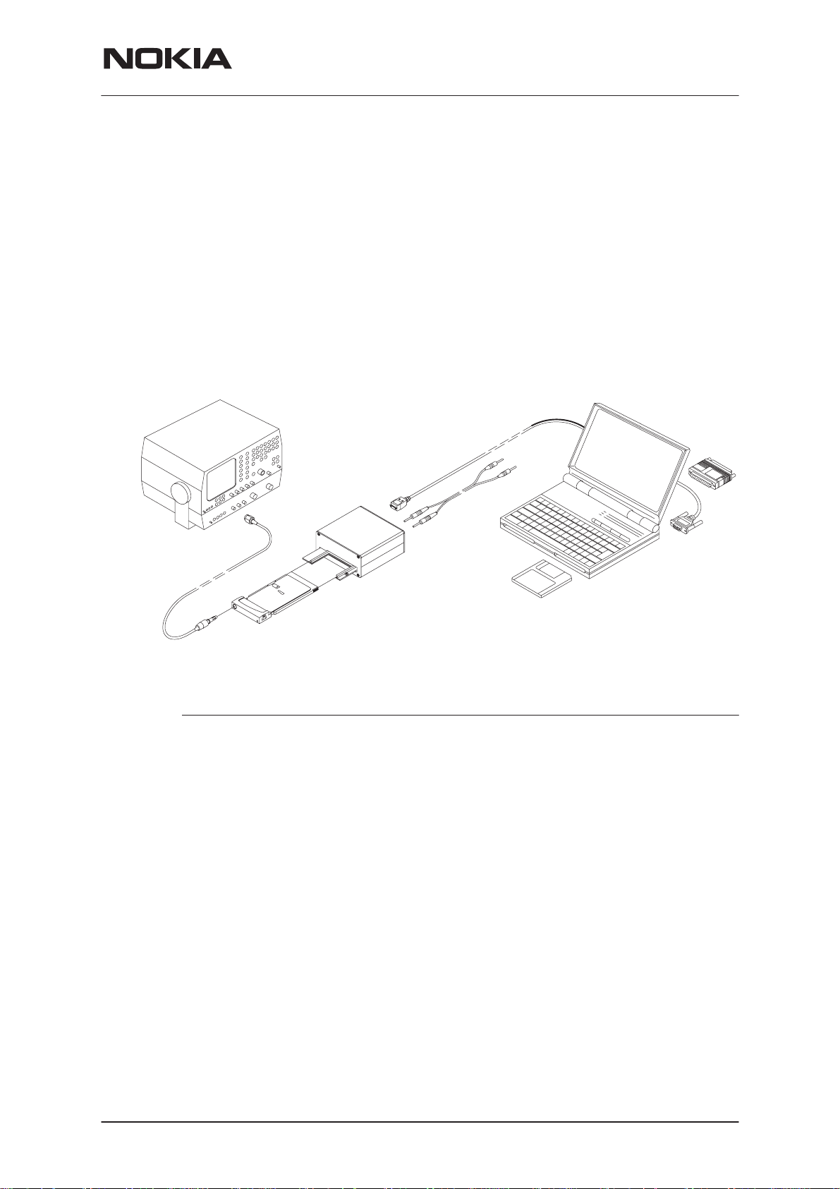
Equipment Setup for RF Tuning the RPM-1
2.
RPM-1
Tuning and flashing instructions
4.
3.
1.
5. and 6.
Item: Service accessory: Product code:
1 Service adapter JBS–23 0770165
2 Service cable DAU–9P (or DAU–9M) 0730109
3 Service RF cable XRP–2S 0730176
4 Software protection key PKD–1 0750018
SW protection key drivers
32 bit drivers for Win95/98/NT 0770125
or 16 bit drivers for Win 3.1x 0770126
5 WinTesla Service SW V 6.03 or newer 0774046
6 WinTesla product specific DLL’s for RPM–1 0774225
Power supply for JBS–23:
Laboratory power supply 3A/12V (adjustable)
4 mm standard test leads. One black and one red lead. In Europe these
can be ordered for example from Farnell.
Issue 1 12/99
Farnell code for 500 mm long 4 mm red test lead: 523–719
Farnell code for 500 mm long 4 mm black test lead: 523–720
Nokia Mobile Phones Ltd.
Page 5
Page 6

RPM-1
Tuning and flashing instructions
PAMS Technical Documentation
Tuning Steps
RX Calibration (AGC + AFC) for both bands
Reference values for the received signal strength meter are program tuned.
RSSI reference signal level programming:
– Select
– Select
– Connect RF generator to RPM–1 antenna conn at 947.067710 MHz.
– Adjust signal generator level to –55 dBm + cable attenuation.
– Press OK button
– Adjust signal generator level to –80 dBm + cable attenuation.
– Press
Service software reports:
A Table of AFC Parameters:
A Table for AGC Calibration:
– Press
– Select
Product –> Band –> GSM
Tuning –> RX Calibration
OK
button.
AFC INIT Value
AFC Slope
PSW Slope
AGC in 3 db steps 0...57 dB
DAC and voltage reading for each gain value
SAVE
button
Product –> Band –> PCN
Page 6
– Select
– Adjust signal generator level to –55 dBm + cable attenuation.
– Press
– Adjust signal generator level to –80 dBm + cable attenuation.
– Press OK button.
Service software reports:
A Table of AFC Parameters:
A Table for AGC Calibration:
– Press
Tuning –> RX Calibration
OK
button
AFC INIT Value
AFC Slope
PSW Slope
AGC in 3 db steps 0...57 dB
DAC and voltage reading for each gain value
SAVE
button
Nokia Mobile Phones Ltd.
Issue 1 12/99
Page 7

RPM-1
PAMS Technical Documentation
Tuning and flashing instructions
I/Q Modulator Amplitude Balance and Phase Shift Tuning
The purpose of this tuning operation is to adjust the I/Q modulator d.c. offsets and the I/Q modulator amplitude balance and phase shift.
I/Q modulator d.c. offsets, amplitude balance and phase shift tuning:
– Select
– Select
Product –> Band –> GSM
Tuning –> TX I/Q...
– Select I/Q tuning values from PC’s memory, phone’s EEPROM or fac-
tory default values.
– Connect spectrum analyzer (with attenuator if needed) to RPM–1 an-
tenna connector.
– Check that TX power level is level 10, channel is 60 and TX data type
is Cont1.
– Adjust spectrum analyzer centre frequency to 902 MHz, Span 200kHz,
Res BW 10 kHz, Video BW 1 kHz and Sweep time at least 0.5 s.
–67.71 kHz +67.71 kHz
D.C. offset
tunings:
Set this value
to minimum
CHF
> 30 dB
> 35 dB
Amplitude &
phase difference:
Set this value
to minimum
– Select the ”TX I d.c. offset” option.
– Adjust the level of centre frequency (CHF signal) to minimum by vary-
– The amplitude difference between CHF–67.7 kHz and CHF must be
– Select option ”TX Q d.c. offset”.
– Adjust the level of signal CHF to minimum by varying D/A converter
– Use the ”Amplitude Difference” option.
Issue 1 12/99
ing D/A converter value with
>30 dB.
<–
and
–>
value with
keys.
Nokia Mobile Phones Ltd.
<–
and –> buttons.
Page 7
Page 8

RPM-1
Tuning and flashing instructions
– Adjust the level of signal CHF+67.7 kHz (902.06777 MHz) to minimum
by varying D/A converter value with <– and –> keys.
– The amplitude difference between CHF+67.7 kHz and CHF–67 kHz
should be >35 dB.
– Select the ”Phase Difference” option.
– Adjust the level of signal CHF+67.7 kHz to minimum by varying D/A
converter value with <– and –> keys.
PAMS Technical Documentation
– When values are correct press
And the same steps for GSM 1800 band.
– Select
– Select
– Select I/Q tuning values from PC’s memory, phone’s EEPROM or fac-
tory default values.
– Check that TX power level is level 10, channel is 700 and TX data type
is Cont1.
– Adjust spectrum analyzer centre frequency to 1747.8 MHz, Span
200kHz, Res BW 10 kHz, Video BW 1 kHz and Sweep time at least
0.5 s.
– Select the ”TX I d.c. offset” option.
– Adjust the level of centre frequency (CHF signal) to minimum by vary-
ing D/A converter value with
– The amplitude difference between CHF–67.7 kHz and CHF should be
>30 dB.
– Select option ”TX Q d.c. offset”.
Product –> Band –> PCN
Tuning –> TX I/Q...
SAVE
<–
and –> buttons.
button.
Page 8
– Adjust the level of signal CHF to minimum by varying D/A converter
<–
and
–>
value with
– Use the ”Amplitude Difference” option.
– Adjust the level of signal CHF+67.7 kHz (1747.86777 MHz) to mini-
mum by varying D/A converter value with <– and –> keys.
– The amplitude difference between CHF+67.7 kHz and CHF–67 kHz
must be >35 dB.
– Select the ”Phase Difference” option.
– Adjust the level of signal CHF+67.7 kHz to minimum by varying D/A
converter value with <– and –> keys.
– When values are correct press
Nokia Mobile Phones Ltd.
keys.
SAVE
button.
Issue 1 12/99
Page 9

PAMS Technical Documentation
Tuning of Transmitter Power Levels
This adjustment loads the power levels of the phone transmitter into the EEPROM. When doing this, a pulse power meter or spectrum analyzer must be
used.
Power levels programming:
RPM-1
Tuning and flashing instructions
– Select
– Select
Product –> Band –> GSM
Tuning –> TX Power...
– Select TX Power tuning values from PC’s memory, phone’s EEPROM
or factory default values.
– Connect pulse power meter or spectrum analyzer to antenna connec-
tor.
– Check that channel is 60.
– Adjust the power level (levels 5, 15, 19 and Base) by clicking the + and
– buttons, and change levels with ↑ and ↓ keys.
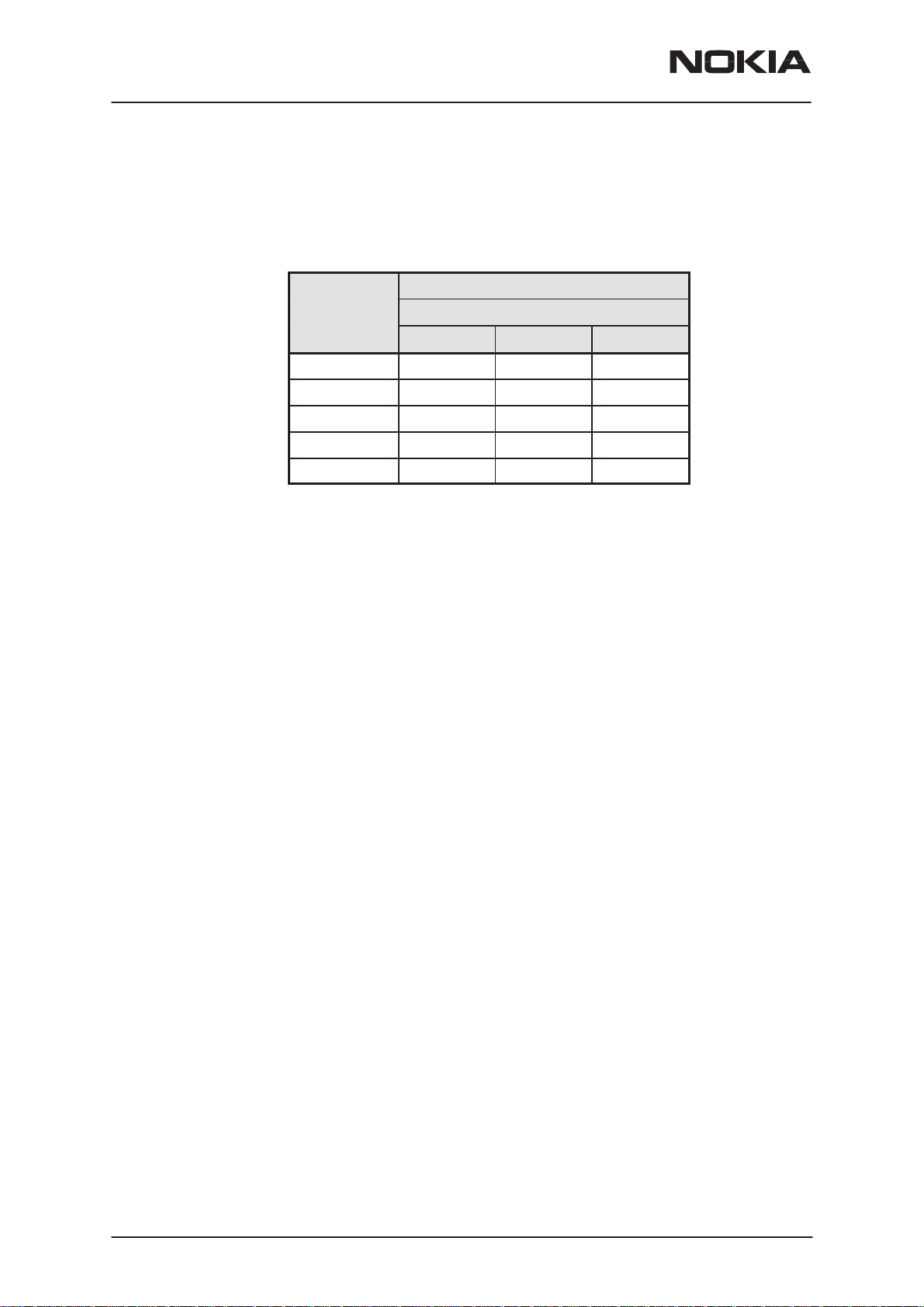
Table 1. GSM 900 TX Tuning Values
Output Power [dBm]
Power level
CH=1 CH=60 CH=124
5 32.5 32.5 32.5
12 19 19 19
15 13
19 6.5 6.5 6.0
BAND=GSM 900
BASE –15
Note: If the base calculation feature is enabled, then the base level is calculated automatically.
– Press
Calculate
button to calculate all other levels.
– Check all TX levels and adjust them is necessary. Refer to TX power
level table at the end of this chapter.
– Once all TX levels for channel 60 are correct, press
SAVE
button.
– Tune power levels 5,12 and 19 for channels 1 and 124 according to
table.
– Once TX levels 5, 12 and 19 for channels 1 and 24 are correct, press
SAVE
button.
And the same steps for GSM 1800 band.
– Select
– Select
Product –> Band –> PCN
Tuning –> TX Power...
– Select TX Power tuning values from PC’s memory, phone’s EEPROM
or factory default values.
Issue 1 12/99
Nokia Mobile Phones Ltd.
Page 9
Page 10
RPM-1
Tuning and flashing instructions
– Check that channel is 700.
– Adjust the power level (levels 0, 11, 15 and Base) by clicking the + and
– buttons, and change levels with ↑
Table 2. GSM 1800 TX Tuning Values
PAMS Technical Documentation
and ↓ keys.
Output Power [dBm]
Power level
CH=512 CH=700 CH=885
0 29.5 29.5 29.5
7 16 16 16
11 8
15 2 2 2
BASE –23
BAND=GSM 1800
Note: If the base calculation feature is enabled, then the base level is calculated automatically.
– Press
Calculate
button to calculate all other levels.
– Check all TX levels and adjust them is necessary. Refer to TX power
level table at the end of this chapter.
– Once all TX levels for channel 700 are correct, press
SAVE
button.
– Tune power levels 0, 7 and 15 for channels 512 and 885 according to
table.
– Once TX levels 0, 7 and 15 for channels 512 and 885 are correct,
press
SAVE
button.
Page 10
Table next page: RPM–1 RF output power levels
Nokia Mobile Phones Ltd.
Issue 1 12/99
Page 11
PAMS Technical Documentation
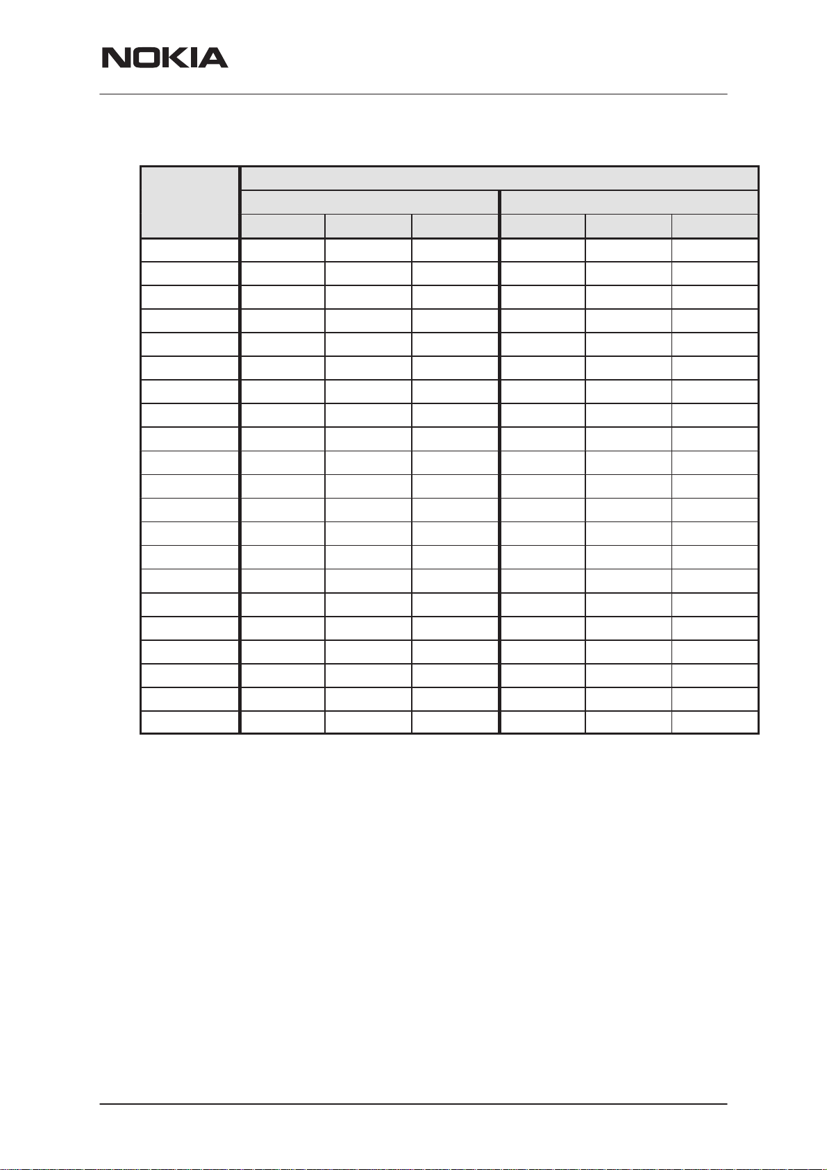
Table 3. RPM–1 RF Output Powers
RPM-1
Tuning and flashing instructions
Output Power [dBm]
Power level
CH=1 CH=60 CH=124 CH=512 CH=700 CH=885
0 ––– ––– ––– + 29.5 + 29.5 + 29.5
1 ––– ––– ––– + 28
2 ––– ––– ––– + 26
3 ––– ––– ––– + 24
4 ––– ––– ––– + 22
5 + 32.5 + 32.5 + 32.5 + 20
6 + 31 + 18
7 + 29 + 16 + 16 + 16
8 + 27 + 14
9 + 25 + 12
10 + 23 + 10
11 + 21 + 8
12 + 19 + 19 + 19 + 6.5
13 + 17 + 5
14 + 15 + 3.5
15 + 13 + 2 + 2 + 2
BAND=GSM 900 BAND=GSM 1800
16 + 11 ––– ––– –––
17 + 9.5 ––– ––– –––
18 + 8 ––– ––– –––
19 + 6.5 + 6.5 + 6.0 ––– ––– –––
Base – 15 – 23
Issue 1 12/99
Nokia Mobile Phones Ltd.
Page 11
Page 12
RPM-1
Tuning and flashing instructions
PAMS Technical Documentation
RPM–1 SW Upgrade (flashing)
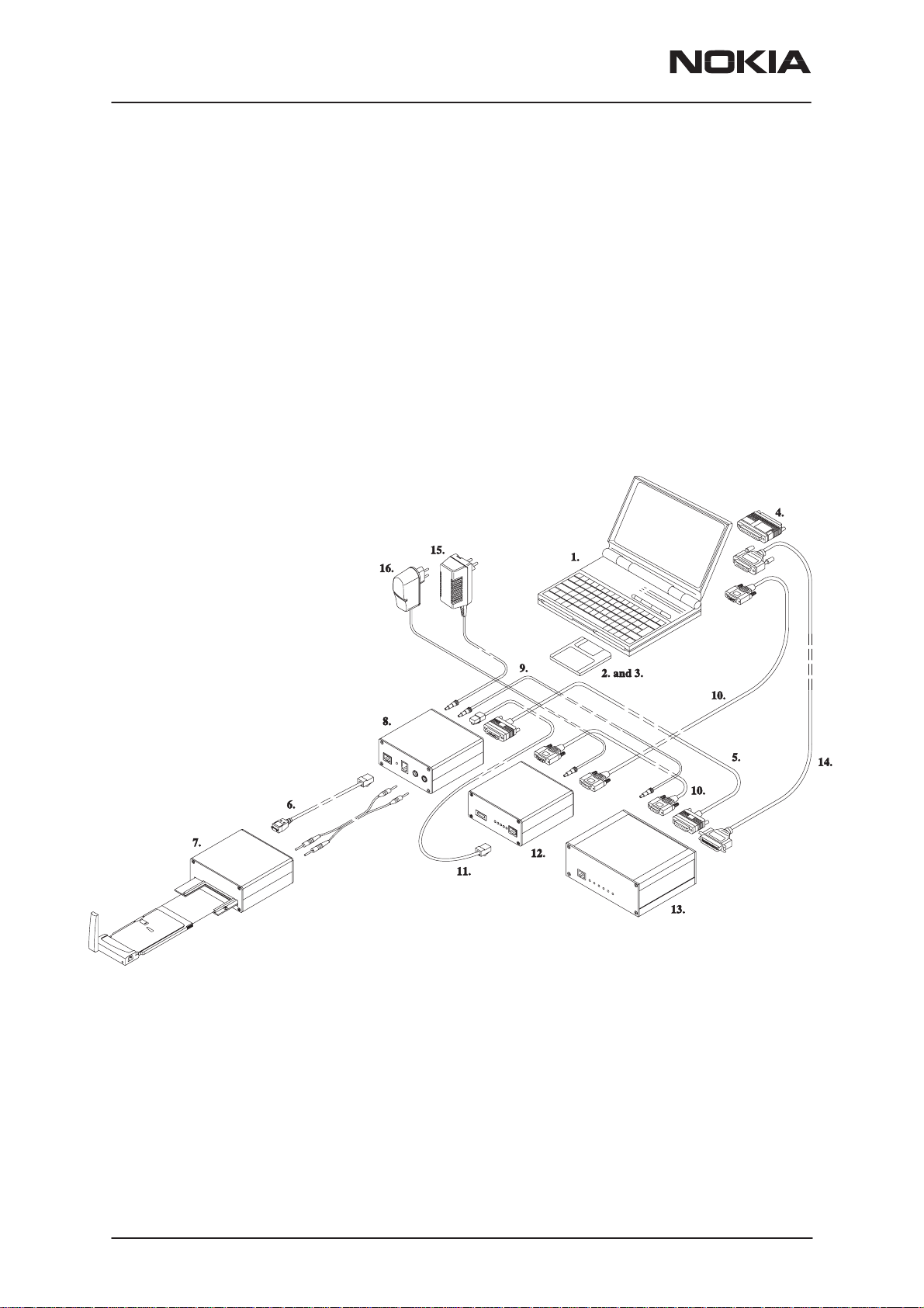
Complete Equipment for RPM–1 SW Upgrade
NOTE!
If you already have DCT3 SW upgrade equipment and you want to change
it to be capable to perform RPM–1 SW upgrade: Then you already have most
of the equipment on your desk.
The complete equipment list and the list of equipment which is needed to
change DCT3 SW upgrade equipment to perform RPM–1 SW upgrade are
illustrated in the next two figures.
Page 12
Nokia Mobile Phones Ltd.
Issue 1 12/99
Page 13

PAMS Technical Documentation
Complete equipment list
Item: Service accessory: Product code:
1 PC environment
2 WinTesla service SW V 6.03 or newer 0774046
3 RPM–1 Service SW, 3.5” diskette 0774225
4 PKD–1 SW protection key 0750018
SW protection key drivers
6 SCH–5A cable 0730166
7 Service adapter JBS–23 0770165
10 AXS–4 cable (first) 0730090
11 Modular cable XCM–1 4626131
12 Flash security box TDF–4 0770106
16 ACH–6E power supply (TDF–4’s power supply) 0675084
RPM-1
Tuning and flashing instructions
486 processor or newer
Win3.1x/95/98/NT
32 bit drivers for Win95/98/NT 0770125
or 16 bit drivers for Win 3.1x 0770126
Power supply cables for JBS–23:
4 mm standard test leads. One black and one red lead. In Europe these
can be ordered for example from Farnell.
Farnell code for 500 mm long 4 mm red test lead: 523–719
Farnell code for 500 mm long 4 mm black test lead: 523–720
FLA–7 Flash loading adapter sales pack 0080326
The following items are included in FLA–7 sales pack:
5 AXS–5 cable
8 FLA 7 flash loading adapter
9 DC power cable SCF–7
Flash prommer FPS–4 sales package 0085095
The following items are included in FPS–4 sales package:
10 AXS–4 cable (second)
13 FPS–4 Flash prommer
14 Centronics cable
15 ACL–3E power supply
NOTE! FPS–4 Must be ordered with memory extension module:
1*SRAM type SF6 0200742
FPS–4 must include sw version 2.22 or newer
SW Diskette for FPS–4, 3.5” floppy 0774043
FPS–4 SW requires Flash Device Support pack v. 1.11
or newer
SW Diskette for Flash Device Support pack 0774228
Issue 1 12/99
Nokia Mobile Phones Ltd.
Page 13
Page 14
RPM-1
Tuning and flashing instructions
PAMS Technical Documentation
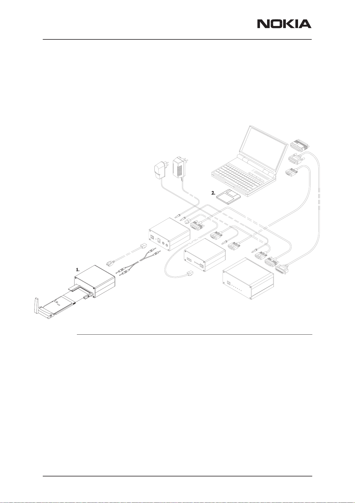
Upgrade Equipment for RPM–1 SW Upgrade
Here is the equipment list in case you already have Nokia 61XX/51XX SW
update capability.
Page 14
Item: Service accessory: Product code:
1 Service Adapter JBS–23 0770165
2 RPM–1 Service SW, 3.5” diskette 0774225
Power supply cables for JBS–23:
4 mm standard test leads. One black and one red lead. In Europe these
can be ordered for example from Farnell.
Farnell code for 500 mm long 4 mm red test lead: 523–719
Farnell code for 500 mm long 4 mm black test lead: 523–720
NOTE! FPS–4 Must be ordered with memory extension module:
1*SRAM type SF6 0200742
FPS–4 must include sw version 2.22 or newer
SW Diskette for FPS–4, 3.5” floppy 0774043
FPS–4 SW requires Flash Device Support pack v. 1.11 or new-
er
SW Diskette for Flash Device Support pack 0774228
Nokia Mobile Phones Ltd.
Issue 1 12/99
Page 15

PAMS Technical Documentation
Software Update Instructions
Previous pages introduced all possible configurations that can be used in
RPM–1 software upgrade. The following chapters contain detailed step–by–
step instructions how to perform this upgrade.
In case that equipment is not working properly:
– Check that connections are made according to insructions.
– Switch the power off from the boxes and PC and restart the whole sys-
tem.
– Clean the contact surfaces.
Software Upgrade
RPM-1
Tuning and flashing instructions
General
Software upgrade is currently possible only by using software upgrade
equipment described earlier.
Equipment Setup instructions
1 Once TDF–4 box is first time used it has to be activated ac-
cording to instructions which come inside the TDF–4 package.
2 Connect boxes, cables and PC according to the connection
diagram.
3 Install FPS4 Prommer SW (release 2.22 or newer). Install also
device files which are included on a separate floppy in the
newest FPS4 sales package.
4 Run setup (type ”setup c:\fps4”) at DOS prompt, where c:\fps4
is the directory where files will be installed.
5 Answer setup program’s questions according to your environ-
ment.
Setting up the PC
Issue 1 12/99
1 Install WinTesla version 6.03 or newer.
2 Install dongle drivers.
3 Install RPM–1 DLLs
Nokia Mobile Phones Ltd.
Page 15
Page 16

RPM-1
Tuning and flashing instructions
Programming with Wintesla interface
When the system has been set up, SW upgrade can be performed according
to the following instructions.
1 Insert RPM–1 in JBS–23’s PC Card slot.
2 Connect SCH–5 in FLA–7’s (or FLA–5’s) ”service cable” con-
nector and other end in JBS–23’s ”SCH–5/DAU–9P” connector.
3 Connect banana cables for power supply between FLA–7 (or
FLA–5) and JBS–23. Be sure to use corret polarity. One cable
from red connector to red connetor and the other cable from
black connector to black connector.
4 Start WinTesla software.
5 Select ”Product –> Open –> RPM–1”.
PAMS Technical Documentation
6 Select ”Dealer –> Flash Phone”.
7 New dialog opens.
8 Select MCU file or use default.
9 Press ”Flash” button.
10 Once program is prompting for restoring user data choose the
selection appropriate for your purposes
11 Programming starts.
12 Flash authority ID, Factory setup values and user settings (op-
tional) are updated.
13 After ”Flash programming is completed” message you can
close the flash dialog.
14 RPM–1 SW has been upgraded, disconnect the product from
JBS–23.
Troubleshooting for SW upgrade
If something went wrong during flashing:
If you have a dead RPM–1:
Page 16
1 Use ”Product –> Open –> RPM–1”. WinTesla will prompt you
’Found COMBOX without phone, open flash only menu?’ An-
swer Yes and then use ”Dealer –> Flash Phone”.
2 This time user settings can not be read. After flashing ’Restore
Default User Settings’ dialog is opened and you can select
which default settings you want to download to RPM–1.
1
[]
Nokia Mobile Phones Ltd.
Issue 1 12/99
 Loading...