

Page 1

Nokia Customer Care
RM-8/RM-47/RM-48 Series Transceivers
3 - Service Software
Instructions
Issue 2 03/2005 Copyright 2005 Nokia Corporation. All rights reserved.
Page 2

ISSUE 2 03/2005
Nokia Customer Care 3 - Service Software Instructions
2 COMPANY CONFIDENTIAL ISSUE 2 03/2005
Copyright © 2005 Nokia. All Rights Reserved.
Page 3

Company confidential RM-8/RM-47/RM-48
Nokia Customer Care
Service Software ............................................................................................................ 5
Overview ......................................................................................................................5
Phoenix ........................................................................................................................5
Supported operating systems..................................................................................... 5
Hardware requirements for using Phoenix................................................................ 5
Introduction ............................................................................................................... 5
Installing Phoenix...................................................................................................... 5
Uninstalling Phoenix ................................................................................................. 6
Data packages ..............................................................................................................7
Before installation ..................................................................................................... 7
Data Package for Phoenix (Product Specific)................................................................ 8
Before installation ........................................................................................................8
Installation of Phoenix data package (product specific) ..............................................9
How to uninstall data package ...................................................................................13
How to Manage Connections .....................................................................................14
Manual Settings....................................................................................................... 15
How to Update Flash Support Files for FPS-8*/FPS-8C and FLS-4*......................... 19
Before installation ......................................................................................................19
Installing the flash support files .................................................................................19
How to update the FPS-8*/FPS-8C Flash Prommer SW ..........................................22
FPS-8 Activation and Deactivation.............................................................................. 24
Activation ..................................................................................................................24
Deactivation ...............................................................................................................26
JBV-1 Docking Station SW ......................................................................................... 27
Before installation ......................................................................................................27
Installing SW needed for the JBV-1 SW update .......................................................28
Updating the JBV-1 docking station software ...........................................................32
RF-tunings: Quick Guide for Tuning With Phoenix.................................................... 35
General remarks .........................................................................................................35
Service Tool Concept for RF Tuning Operations ........................................................ 36
General instructions for tuning: .................................................................................36
RF Tuning after repairs ..............................................................................................37
Semi-automatic Calibrations & Measurements - step by step: RX/TX and GSM-Bands 38
RX tunings .................................................................................................................38
Rx calibration GSM1800 and GSM1900 ................................................................ 41
RX band filter response compensation ......................................................................44
Rx band filter response GSM850 ............................................................................ 45
Autotuning............................................................................................................... 46
Rx band filter response GSM 900, GSM 1800 and GSM 1900.............................. 48
RX channel select filter calibration ...........................................................................48
TX power level tuning ...............................................................................................50
Tx power level tuning GSM900, GSM 1800 and GSM 1900 in GMSK mode ...... 50
Tx power level tuning GSM900, GSM1800 and GSM1900 in EDGE mode ......... 53
TX I/Q tuning ............................................................................................................54
Fully Automatic Calibration, Tuning & Measurement by Phoenix “Auto-Tune”....... 60
Preparations for Phoenix ............................................................................................60
Compensation of cable and jig losses ..................................................................... 60
GPIB interface......................................................................................................... 61
Issue 2 01/2005 Copyright 2005 Nokia Corporation. All rights reserved. Page 3
Page 4

RM-8/RM-47/RM-48 Company confidential
Nokia Customer Care
Automatic tuning procedure ......................................................................................61
Log file .................................................................................................................... 62
Service Tool Concept For Baseband Tuning Operations............................................. 63
Service concept for RM-8/RM-47/RM-48/RM-47 baseband tunings and RF testing 64
Baseband Tuning operations........................................................................................ 65
Energy management tuning .......................................................................................65
Flashing Setup Instructions.......................................................................................... 67
POS (Point of Sales) flash concept ............................................................................67
Module jig concept ....................................................................................................68
JBV-1 flash concept ...................................................................................................69
JBV-1 Service concept ..............................................................................................70
Parallel flash concept .................................................................................................71
Page 4 Copyright 2005 Nokia Corporation. All rights reserved. Issue 2 01/2005
Page 5

Issue 2 03/2005
Nokia Customer Care
Service Software
■ Overview
The following steps will be required to use service software with RM-8/RM-47/RM-48/RM-48.
• Install Phoenix Service Software.
• Install data package for RM-8/RM-47/RM-48/RM-48 for your region.
• FPS-8 flash update.
• JBV-1 docking station SW update.
■ Phoenix
Phoenix is the new generation service software for reprogramming, testing and tuning the
phone. It has been designed to meet the challenges in servicing modern cellular phone technology.
The Phoenix program has been built using component architecture. This means that the actual
program is small and most of the program’s functionality is divided into dynamically loaded
modules (DLLs).
Supported operating systems
Windows 2000 and XP.
Hardware requirements for using Phoenix
Minimum:
Processor 300 MHz, RAM memory 64 MB, disk space 100 MB.
Recommended for Windows 2000:
Processor 700 MHz, RAM memory 256 MB, disk space 150 MB.
Introduction
This section briefly describes how to install the Phoenix software and includes some basic information on how to use the program. For more detailed information, please refer to Phoenix
Help files. Each feature in Phoenix has its own Help function, which can be activated while running the program.
Press the F1 key or the feature’s Help button to activate a Help file.
Installing Phoenix
Phoenix Service Software 2004.39.7.70 or later required.
It is recommended to uninstall the previous RM-8/RM-47/RM-48 Phoenix package before installing the new one. Do it as follows:
• Download the latest Phoenix release. Please contact your regional After Market
Services point for information on where to download the latest release.
Download and read the release notes which have useful information on the software version you are using.
• Download the latest data packages for the products you will be using.
Issue 2 03/2005 COMPANY CONFIDENTIAL 1
Copyright © 2005 Nokia. All Rights Reserved.
Page 6
RM-8/RM-47/RM-48
Nokia Customer Care
• Before you start installing the program, check that the dongle is attached to the parallel port. Contact your supervisor in order to obtain a suitable dongle.
Administrator rights are required in order to be able to install Phoenix.
• Install Phoenix by executing the Phoenix installation package and follow the instructions on the screen.
Initially, the setup files are extracted into the file system.
Note: If the setup files are already extracted (left in the file system from previous
installation) the “Overwrite Protection” dialog appears. Always click “Yes to All” to
overwrite the existing setup files.
The installation checks that the latest supported dongle driver version is installed.
The dongle driver is installed if there is no previous installation of the dongle driver or if the installed dongle driver is older than the latest supported version.
Note: If the dongle driver is installed during installation, you need to reboot your PC and restart
the installation after reboot.
Program files are stored under C:\Program Files\Nokia\Phoenix (default).
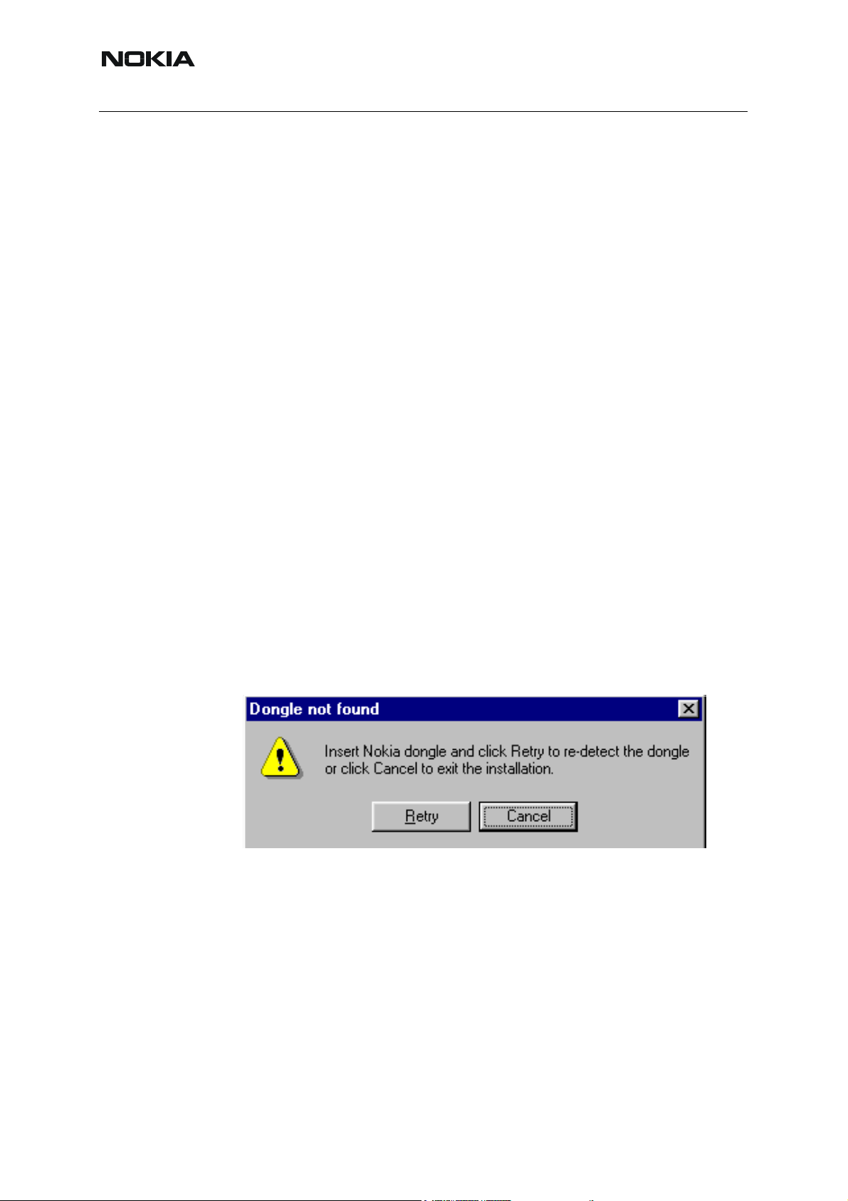
If at any point during installation you get this message, Dongle is not found and installation can´t
continue.
Possible reasons may be defective or too old PKD-1Dongle (five digit serial number Dongle
when used with FPS-8 Prommer) or that the FLS-4S POS Flash Dongle is defective or power
to it is not supplied by external charger.
Check the COM /parallel ports used first! After correcting the problem Installation can be restarted.
Uninstalling Phoenix
If you need to remove Phoenix Service Software from your computer:
• Make sure that the dongle is attached.
• Go to the Control Panel and select Add/Remove Programs.
• Select Phoenix Service software Axx 200x.xx.x.xx.
•Click Change/Remove then OK to remove the application.
You may have to reboot your PC after uninstallation.
2 COMPANY CONFIDENTIAL Issue 2 03/2005
Copyright © 2005 Nokia. All Rights Reserved.
Page 7

Issue 2 03/2005
Nokia Customer Care
■ Data packages
The product data package contains all product specific data to make the Phoenix Service Software and tools usable with a certain phone model. Each product has its own data package
(DP).
Data files are stored under C:\Program Files\Nokia\Phoenix (default).
It also includes the latest version of the flash update package for FLS-4S* and FPS-8*.
Note! If you have different product packages installed, components are uninstalled only if they are not included in other product packages.
Before installation
• Check that the dongle is attached to the parallel port of your computer.
• Install Phoenix Service SW.
• Download the installation package (e.g. RM-8_dp_EA_v_1_0.exe) to your computer (e.g. C:\TEMP).
• Close all other programs.
• Run the installation package (e.g. RM-8_dp_EA_ v_1_0.exe) and follow the instructions on the screen.
If you already have the Phoenix Service SW installed on your computer, sooner or later there
will be need to update it when new versions are released.
Please note that very often the Phoenix Service SW and the phone specific data package for
Phoenix come in pairs, meaning that a certain version of Phoenix can only be used with a certain version of the data package. Always use the latest available versions of both. Instructions
can be found in phone model specific Technical Bulletins.
Issue 2 03/2005 COMPANY CONFIDENTIAL 3
Copyright © 2005 Nokia. All Rights Reserved.
Page 8
RM-8/RM-47/RM-48
Nokia Customer Care
Data Package for Phoenix (Product Specific)
■ Before installation
Product Data Package contains all product specific data to make the Phoenix Service Software
and tools usable with a certain phone model.
It also includes the latest version of flash update package for FLS-4* and FPS-8*/FPS-8C
• Check that the Dongle is attached to the parallel port of your computer.
• Install Phoenix Service SW
• Download the installation package (e.g. RM-8/RM-47/RM-48_dp_1.00.exe) to
your computer (e.g. C:\TEMP)
• Close all other programs
• Run the application file (e.g.RM-8/RM-47/RM-48_dp_1.00.exe) and follow instructions on the screen
If you already have the Phoenix Service SW installed on your computer, sooner or later there
will be need to update it when new versions are released.
Please note that very often the Phoenix Service SW and the Phone Specific Data Package for
Phoenix come in pairs, meaning that certain version of Phoenix can only be used with certain
version of Data Package. Always use the latest available versions of both. Instructions can be
found in phone model specific Technical Bulletins.
4 COMPANY CONFIDENTIAL Issue 2 03/2005
Copyright © 2005 Nokia. All Rights Reserved.
Page 9
Issue 2 03/2005
Nokia Customer Care
■ Installation of Phoenix data package (product specific)
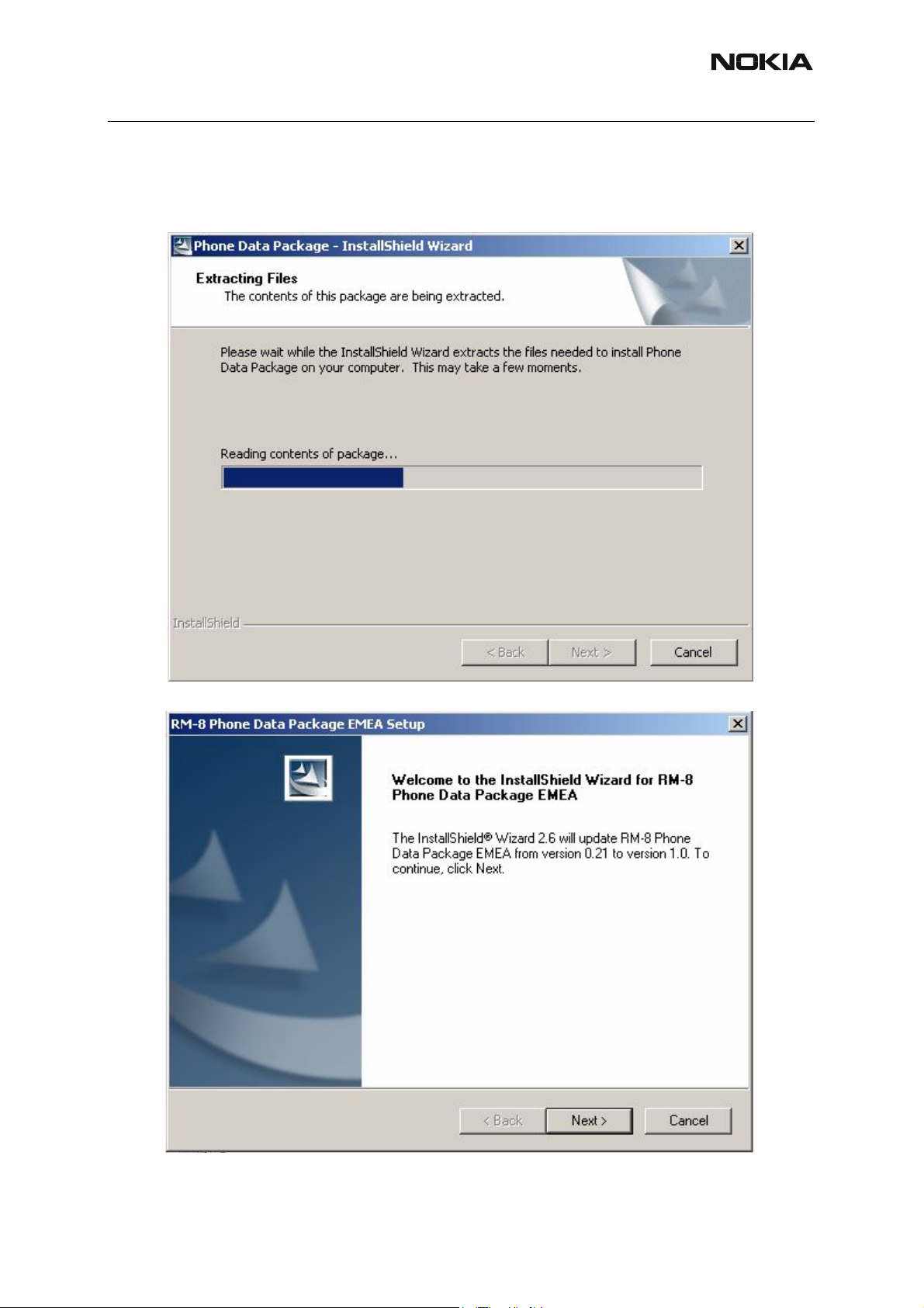
Run the RM-8/RM-47/RM-48_dp_v_1.00.exe to start installation.
When you choose “Next” the files needed for installation will be extracted. Please wait…
RM-8/RM-47/RM-48
Choose “Next” to continue.
From this view you can see the contents of the Data Package.
Issue 2 03/2005 COMPANY CONFIDENTIAL 5
Copyright © 2005 Nokia. All Rights Reserved.
Page 10
RM-8/RM-47/RM-48
Nokia Customer Care
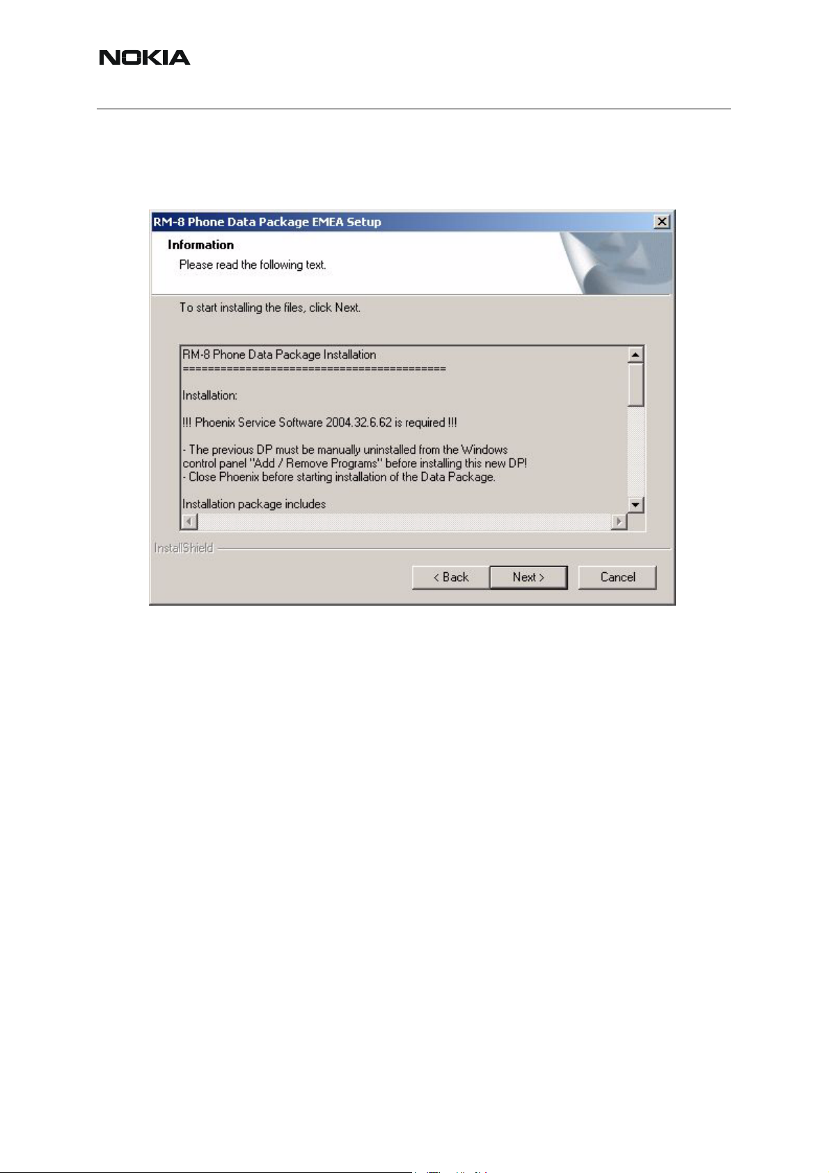
Read the text carefully.
There should be information about the Phoenix version needed with this data package. Choose
“Next”.
6 COMPANY CONFIDENTIAL Issue 2 03/2005
Copyright © 2005 Nokia. All Rights Reserved.
Page 11
Issue 2 03/2005
Nokia Customer Care
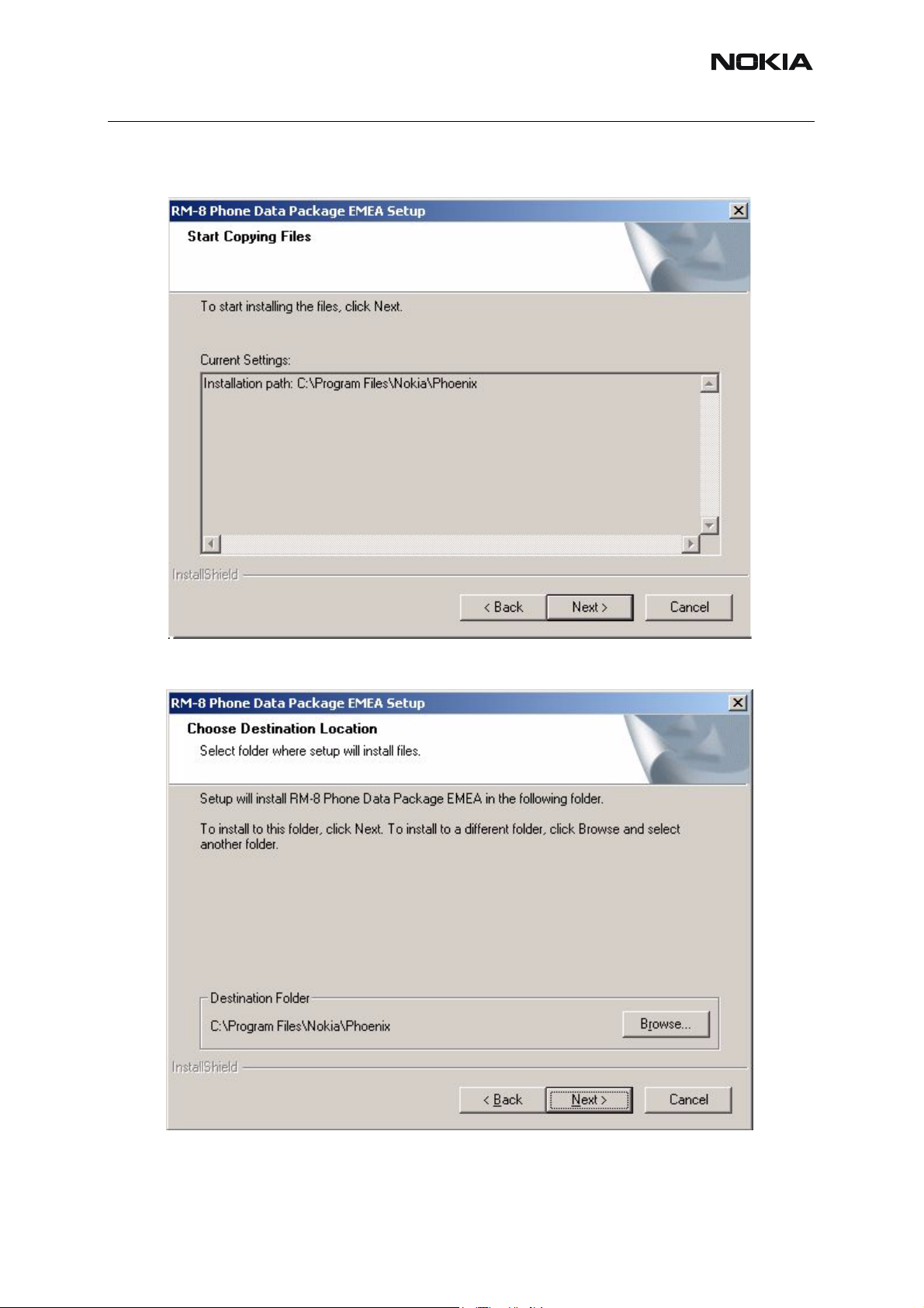
Install Shield checks where the Phoenix application is installed and the directory is shown.
Choose “Next” to continue.
Confirm location and choose “Next” to continue.
Phone model specific files will be installed. Please wait.
Issue 2 03/2005 COMPANY CONFIDENTIAL 7
Copyright © 2005 Nokia. All Rights Reserved.
Page 12
Nokia Customer Care
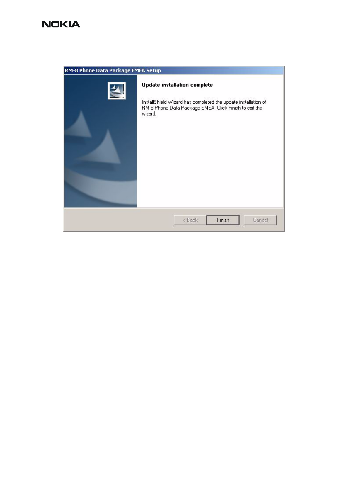
Choose “Finish” to complete installation.
RM-8/RM-47/RM-48
You now have all phone model specific files installed in your Phoenix Service SW.
8 COMPANY CONFIDENTIAL Issue 2 03/2005
Copyright © 2005 Nokia. All Rights Reserved.
Page 13
Issue 2 03/2005
Nokia Customer Care
■ How to uninstall data package
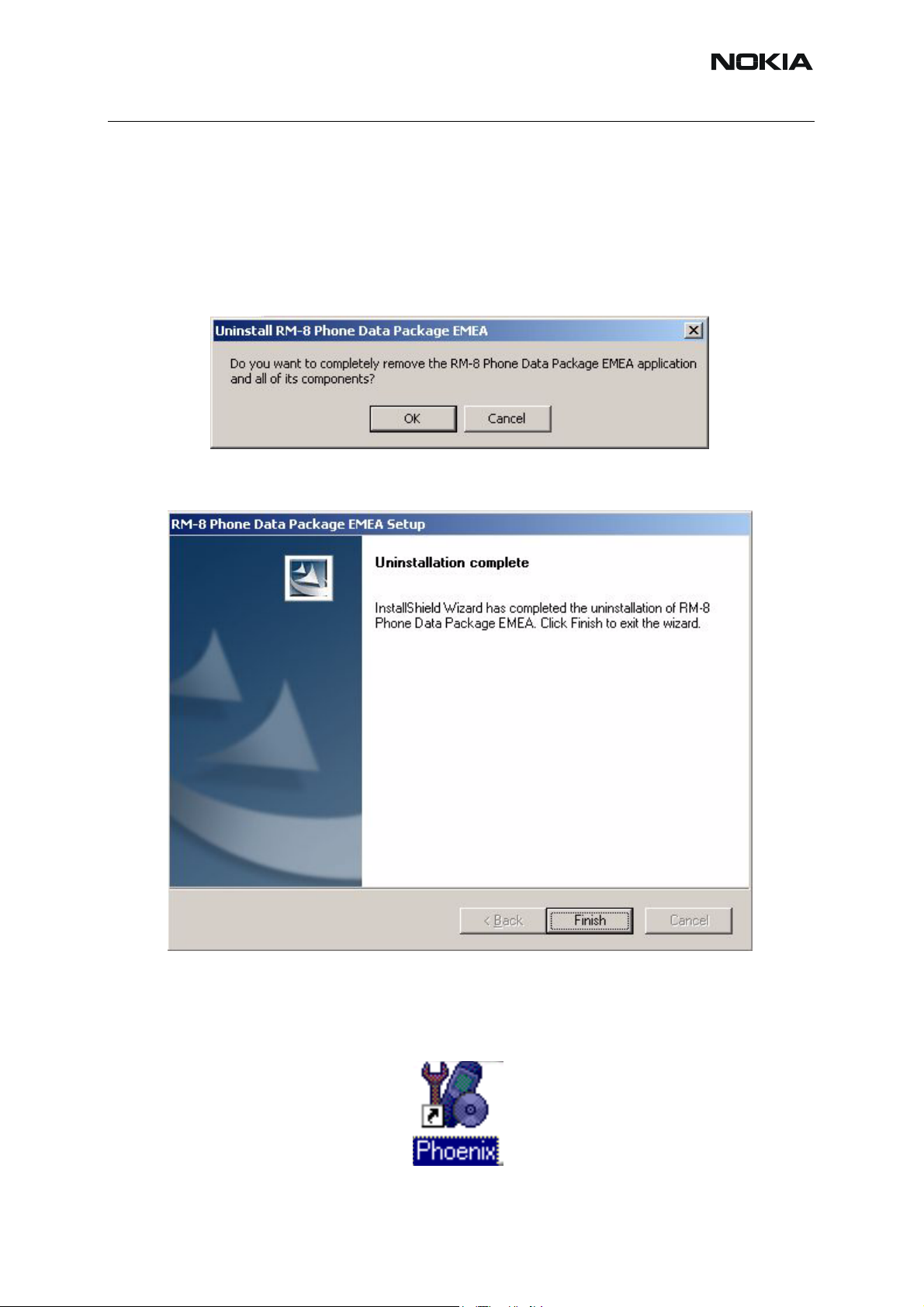
Uninstallation can also be done manually from Windows Control Panel / Add / Remove Programs/ “RM-8/RM-47/RM-48 Phone Data Package”.
If you try to install the same version of Phoenix Data Package that you already have, you are
asked if you want to uninstall the version you have on your PC. Answer “OK” to uninstall, “Cancel” if you don’t want to uninstall. Older versions of data packages do not need to be uninstalled.
Once the previously installed Data package is uninstalled, choose “Finish”.
Run the RM-8/RM-47/RM-48_dp_v_1.00.exe again to continue installation from the beginning.
■ How to Manage Connections
Start Phoenix Service SW and Login.
Issue 2 03/2005 COMPANY CONFIDENTIAL 9
Copyright © 2005 Nokia. All Rights Reserved.
Page 14
RM-8/RM-47/RM-48
Nokia Customer Care
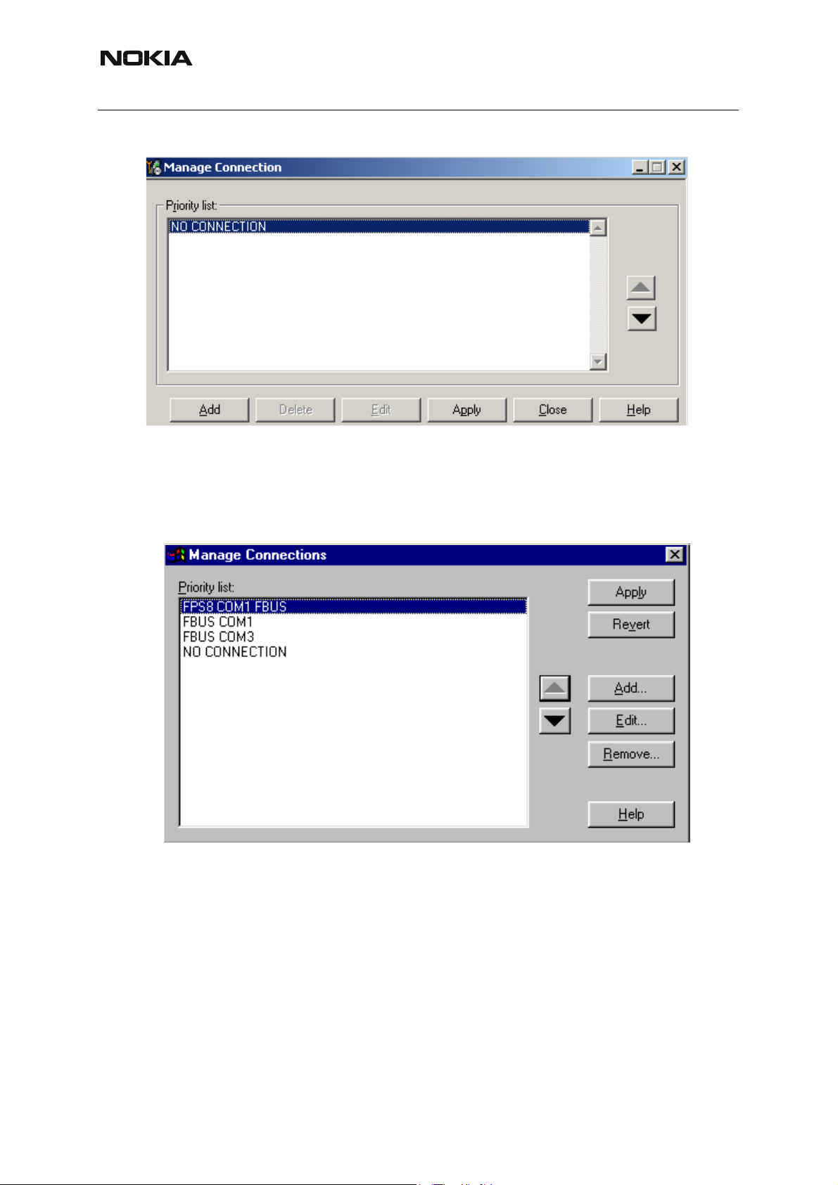
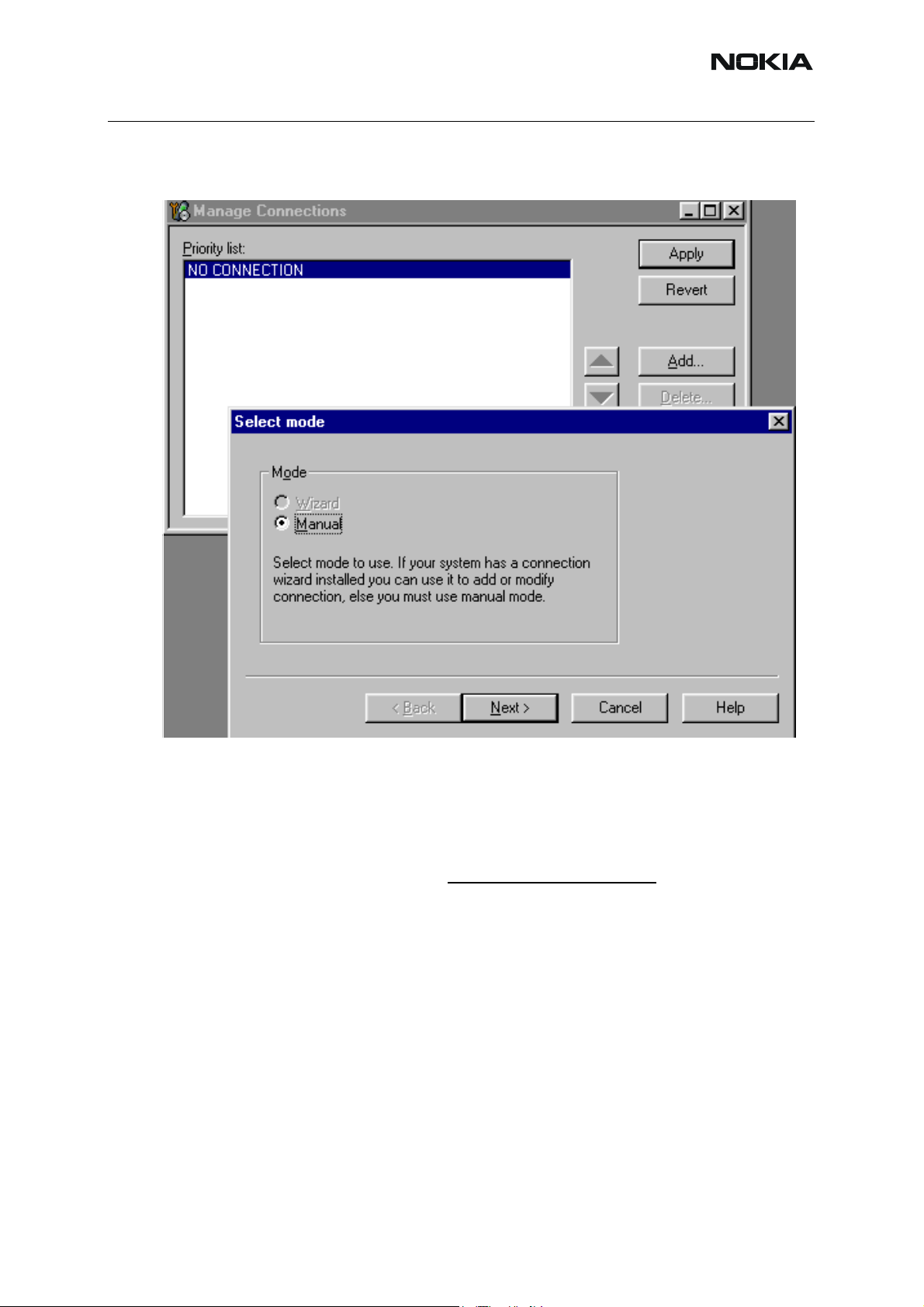
Choose “Manage Connections” From “File” – Menu
Existing connections can be selected, edited, deleted and new ones created by using this dialog.
A connection can be created either manually or by using a Connection Wizard.
To add new connection, choose “Add” and select if you want to create it manually or by using
the Wizard.
10 COMPANY CONFIDENTIAL Issue 2 03/2005
Copyright © 2005 Nokia. All Rights Reserved.
Page 15
Issue 2 03/2005
Nokia Customer Care
Choose “Next” to continue.
In the next dialogs you will be asked to select some settings for the connection
Manual Settings
A) For FLS-4S POS Flash Device choose following connection settings
Media: FBUS
COM Port: Virtual COM Port used by FLS-4 Please check this always!
(To check please go to Windows / Control Panel / FLS Virtual Port / Configuration)
B) For FPS-8 Flash Prommer choose following connection settings:
Media: FPS-8
Port Num: COM Port where FPS-8 is connected
COMBOX_DEF_MEDIA: FBUS
Choose “Finish” to complete.
Issue 2 03/2005 COMPANY CONFIDENTIAL 11
Copyright © 2005 Nokia. All Rights Reserved.
Page 16
RM-8/RM-47/RM-48
Nokia Customer Care
If you use the Wizard, connect the tools and a phone to your PC and the wizard will automatically try to configure the correct connection.
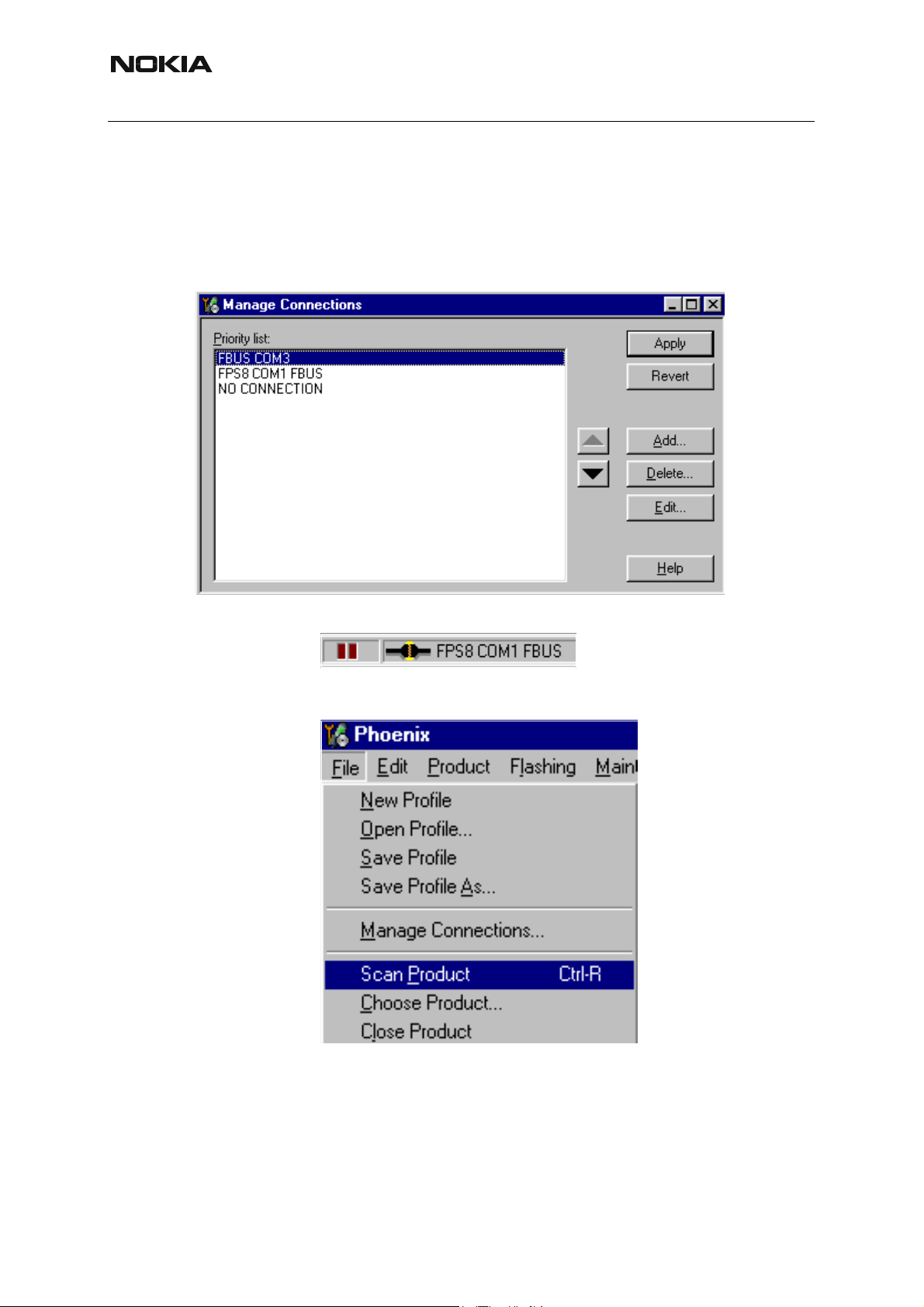
Activate the connection you want to use by clicking it and use up/down arrows to move it on
top of the list. Choose “Apply”.
The connection is now selected and can be used after closing the “Manage Connections” window.
Selected connection will be shown on the right hand bottom corner of the screen.
To use the selected connection, connect the phone to Phoenix with correct service tools, make
sure that it is switched on and select “Scan Product”.
12 COMPANY CONFIDENTIAL Issue 2 03/2005
Copyright © 2005 Nokia. All Rights Reserved.
Page 17
Issue 2 03/2005
Nokia Customer Care
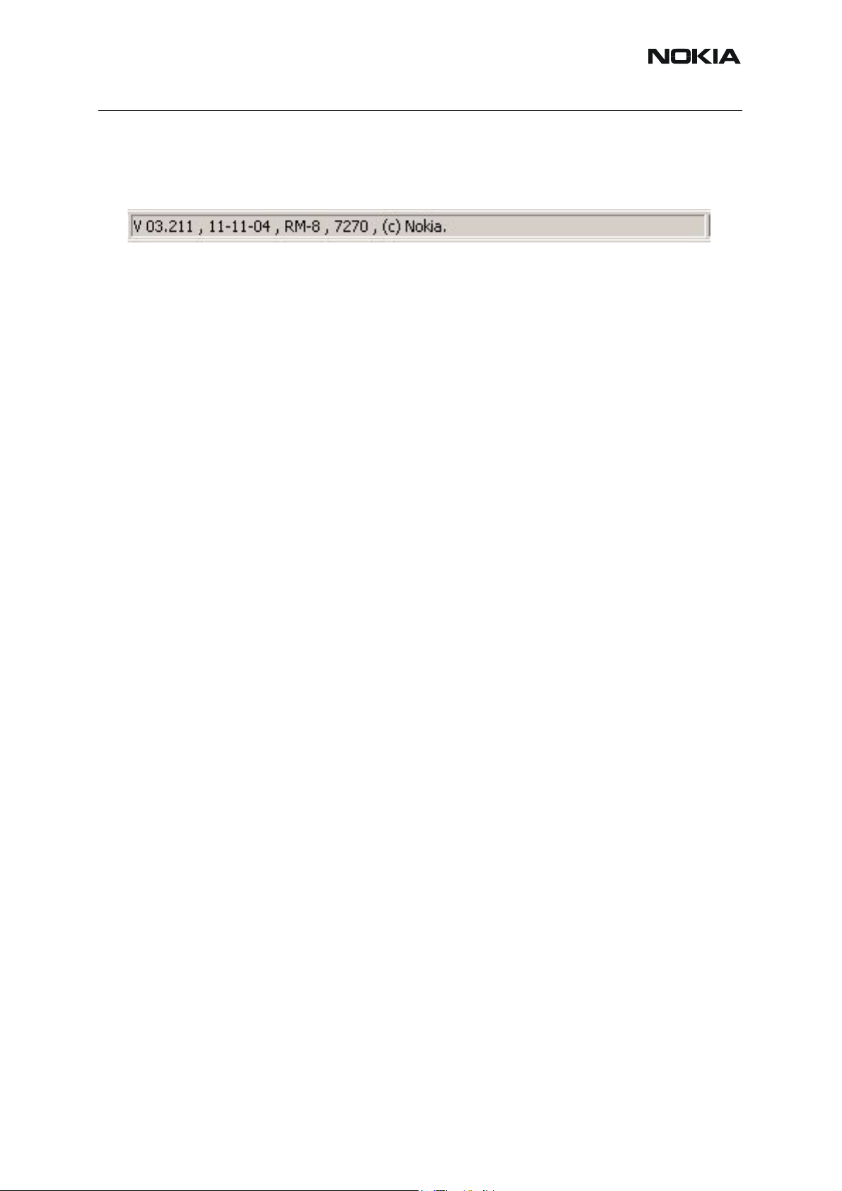
When the Product is found, Phoenix will load product support and when everything is ready,
name of the loaded product support module and its version will be shown on the bottom of the
screen.
Issue 2 03/2005 COMPANY CONFIDENTIAL 13
Copyright © 2005 Nokia. All Rights Reserved.
Page 18

Nokia Customer Care
[This page left intentionally blank]
RM-8/RM-47/RM-48
14 COMPANY CONFIDENTIAL Issue 2 03/2005
Copyright © 2005 Nokia. All Rights Reserved.
Page 19
Issue 2 03/2005
Nokia Customer Care
How to Update Flash Support Files for FPS-8*/FPS8C and FLS-4*
■ Before installation
• Install Phoenix Service SW and Phoenix data package.
• Install the phone model Specific Datapackage for Phoenix
• The flash support files are delivered in the same installation package with Phoenix
data package.
• Normally it is enough to install the data package only before updating the FPS-8.
• Separate installation package is for flash support files are available, and the files
can be updated according to this instruction.
■ Installing the flash support files
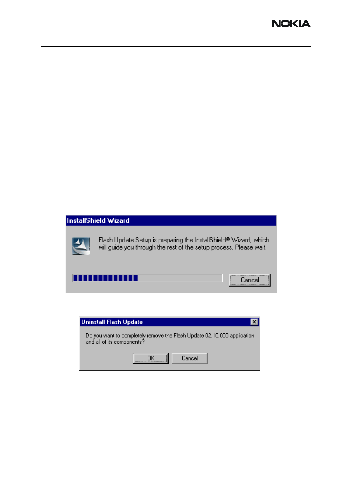
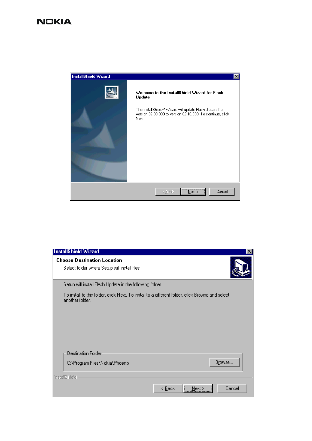
Start by double clicking eg. flash_update_02_10_00.exe. Installation begins.
If you already have the same Flash Update package files installed, you need to confirm if you
want them to be reinstalled.
Issue 2 03/2005 COMPANY CONFIDENTIAL 1
Copyright © 2005 Nokia. All Rights Reserved.
Page 20
Nokia Customer Care
Choose “Next” to continue installation
RM-8/RM-47/RM-48
It is highly recommended to install the files to the default destination folder C:\Program
Files\Nokia\Phoenix.
Choose “Next” to continue. You may choose another location by selecting “Browse” (not recommended).
2 COMPANY CONFIDENTIAL Issue 2 03/2005
Copyright © 2005 Nokia. All Rights Reserved.
Page 21
Issue 2 03/2005
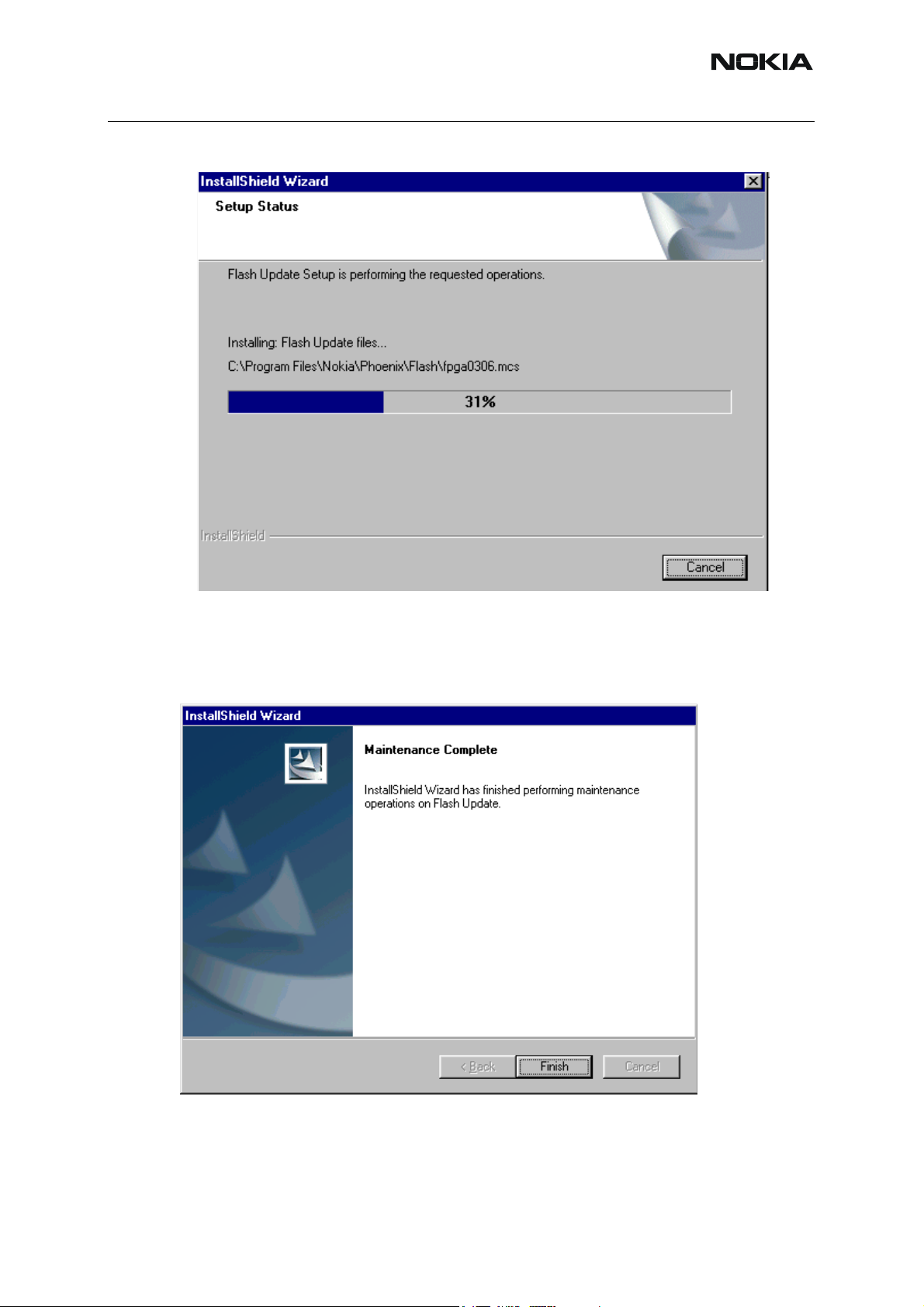
Installation continues…
Nokia Customer Care
Choose “Finish” to complete procedure.
• FLS-4 can be used right after Flash Update Package is installed.
• FPS-8*/FPS-8C must be updated by using Phoenix!
Issue 2 03/2005 COMPANY CONFIDENTIAL 3
Copyright © 2005 Nokia. All Rights Reserved.
Page 22
RM-8/RM-47/RM-48
Nokia Customer Care
■ How to update the FPS-8*/FPS-8C Flash Prommer SW
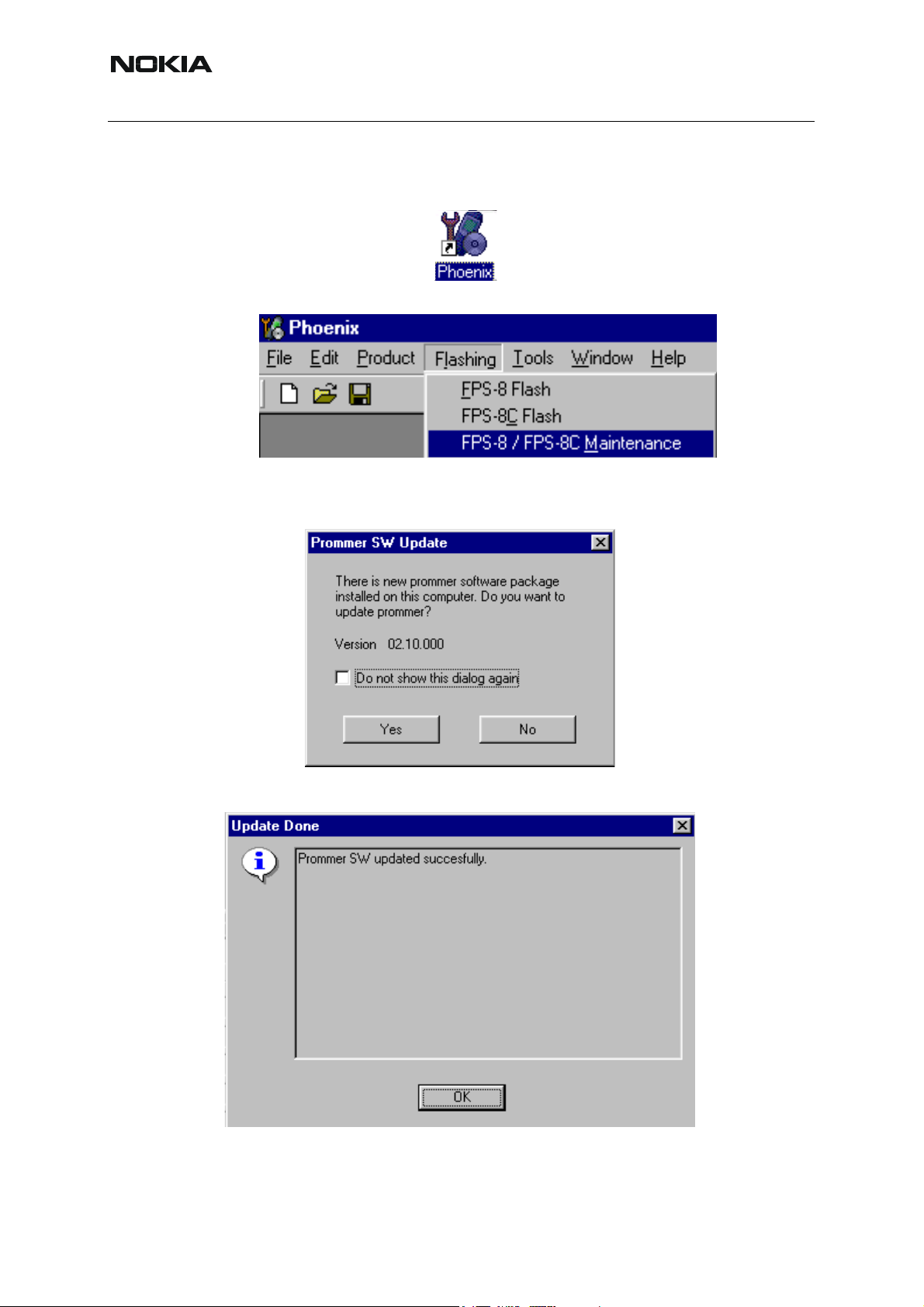
Start Phoenix Service Software
Select”FPS-8 / FPS-8*/FPS-8C maintenance” from”Flashing” menu.
When new FPS-8 flash update package is installed to computer you will be asked to update the
files to your FPS-8 Prommer. Select ”Yes” to update files..
0200
Update procedure takes a couple of minutes.
4 COMPANY CONFIDENTIAL Issue 2 03/2005
Copyright © 2005 Nokia. All Rights Reserved.
Page 23
Issue 2 03/2005
Nokia Customer Care
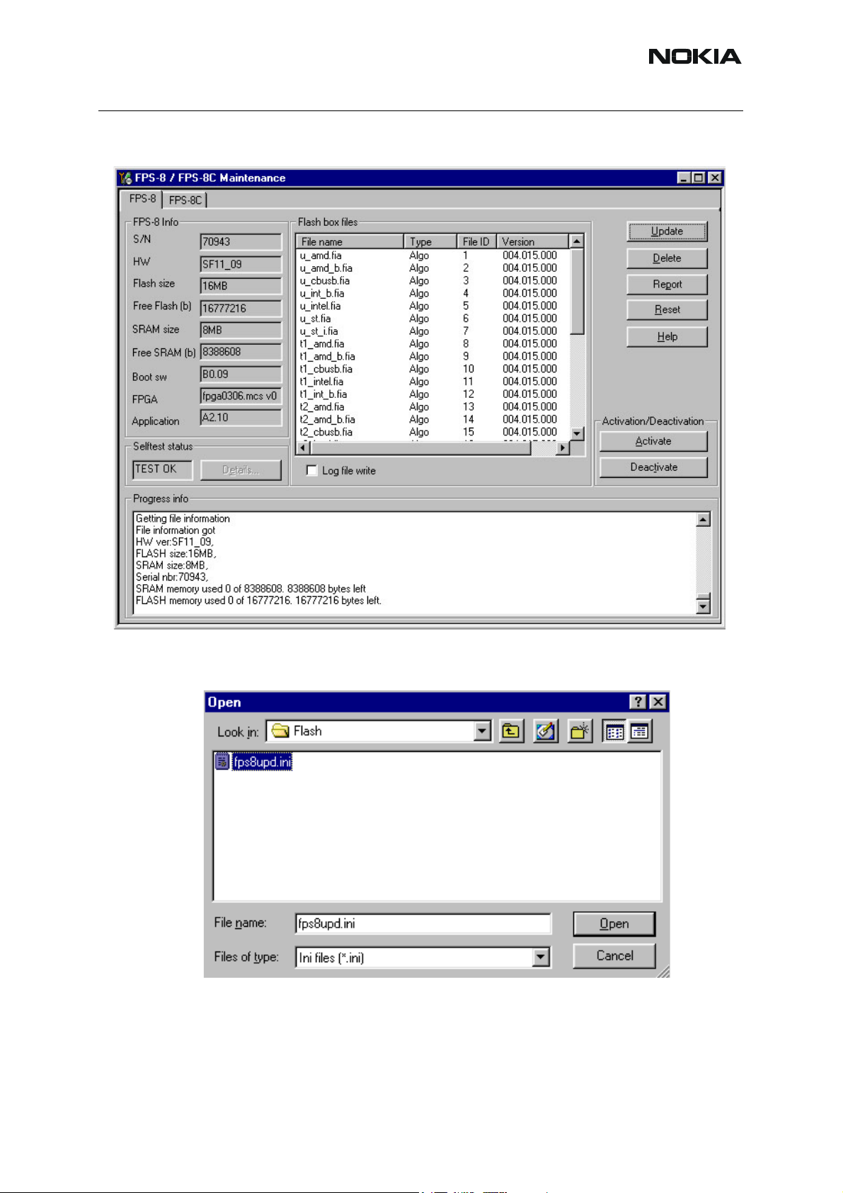
FPS-8 SW can also be updated by pressing ”Update” button and selecting appropriate
fps8upd.ini file under C:\Program Files\Nokia\Phoenix\Flash - directory
All files can be loaded separately to FPS-8. To do this, just press right mouse button in “Flash
box files” window and select file type to be loaded.
More information and help can be found from the “Help” dialog.
Issue 2 03/2005 COMPANY CONFIDENTIAL 5
Copyright © 2005 Nokia. All Rights Reserved.
Page 24

RM-8/RM-47/RM-48
Nokia Customer Care
FPS-8 Activation and Deactivation
• Before the FPS-8 can be successfully used for phone programming, it must be
first activated.
• If there is a need to send FPS-8 box to somewhere e.g. for repair, box must be
first deactivated.
■ Activation
Before FPS-8 can be successfully used for phone programming, it must be first activated.
Fill in first “FPS-8 activation request” sheet, in the FPS-8 sales package and follow the instructions in the sheet.
When activation file is received (e.g. 00000.in), copy it to C:\ProgramFiles\Nokia\Phoe-
nix\BoxActivation - Directory on your computer (This directory is created when Phoenix is installed).
Start Phoenix Service Software.
Select ”FPS-8 / FPS-8*/FPS-8C maintenance” from ”Flashing” menu.
Select “Activate” from the “FPS8/8C Maintenance” – UI.
6 COMPANY CONFIDENTIAL Issue 2 03/2005
Copyright © 2005 Nokia. All Rights Reserved.
Page 25

Issue 2 03/2005
Nokia Customer Care
The activation file you saved to C:\ProgramFiles\Nokia\Phoenix\BoxActivation - directory will
be shown (e.g. 00000.in), check that it is correct.
Box will be activated when you choose “Open”
Turn FPS-8 power off and on to complete activation
Issue 2 03/2005 COMPANY CONFIDENTIAL 7
Copyright © 2005 Nokia. All Rights Reserved.
Page 26

Nokia Customer Care
■ Deactivation
Start Phoenix Service Software.
Select ”FPS-8 / FPS-8*/FPS-8C maintenance” from ”Flashing” menu
Select “Deactivate” from the “FPS8/8C Maintenance” – UI.
Confirm Deactivation by choosing “Yes”, Box will be deactivated.
RM-8/RM-47/RM-48
Turn FPS-8 power off and on to complete deactivation.
8 COMPANY CONFIDENTIAL Issue 2 03/2005
Copyright © 2005 Nokia. All Rights Reserved.
Page 27

Issue 2 03/2005
Nokia Customer Care
JBV-1 Docking Station SW
The JBV-1 Docking Station is a common tool for all DCT-4 generation products. In order to
make the JBV-1 usable with different phone models, a phone specific Docking Station Adapter
is used for different service functions.
The JBV-1 Docking Station contains Software (Firmware) which can be updated.
You need the following equipment to be able to update JBV-1 software:
• PC with USB connection
• Operating System supporting USB (Not Win 95 or NT)
• USB Cable (Can be purchased from shops or suppliers providing PC hardware and accessories)
• JBV-1 Docking Station
• External Power Supply 11-16V
■ Before installation
• Download Jbv1_update.zip – file to your computer (e.g. C:\TEMP) from your download
web site.
• Close all other programs
• Follow instructions on the screen
Issue 2 03/2005 COMPANY CONFIDENTIAL 9
Copyright © 2005 Nokia. All Rights Reserved.
Page 28

RM-8/RM-47/RM-48
Nokia Customer Care
■ Installing SW needed for the JBV-1 SW update
Note: DO NOT CONNECT THE USB CABLE / JBV-1 TO YOUR COMPUTER YET!
Run Jbv1_update.zip file and start SW Installation by double clicking Setup.exe.
Files needed for JBV-1 Package Setup Program will be extracted.
Installation begins, please read the information shown and Choose “Next” to continue.
10 COMPANY CONFIDENTIAL Issue 2 03/2005
Copyright © 2005 Nokia. All Rights Reserved.
Page 29

Issue 2 03/2005
Nokia Customer Care
Use suggested destination folder where JBV-1 SW Package will be installed and choose “Next”
to continue.
Select “Full” Installation and choose “Next” to continue
Issue 2 03/2005 COMPANY CONFIDENTIAL 11
Copyright © 2005 Nokia. All Rights Reserved.
Page 30

RM-8/RM-47/RM-48
Nokia Customer Care
Program Folder will be created. Choose “Next” to continue, Software files will be installed.
After successful installation, choose “Finish” to complete.
NOW YOU CAN CONNECT THE USB CABLE / JBV-1 TO YOUR COMPUTER!
Connect power to JBV-1 (11-16V DC) from external power supply, then connect USB Cable between JBV-1 USB connector and PC.
12 COMPANY CONFIDENTIAL Issue 2 03/2005
Copyright © 2005 Nokia. All Rights Reserved.
Page 31

Issue 2 03/2005
Nokia Customer Care
Windows will detect connected USB cable and detect drivers for new HW.
Follow the instructions and allow Windows to search and install the best drivers available. After
this procedure the actual JBV-1 SW update can begin.
Issue 2 03/2005 COMPANY CONFIDENTIAL 13
Copyright © 2005 Nokia. All Rights Reserved.
Page 32

RM-8/RM-47/RM-48
Nokia Customer Care
■ Updating the JBV-1 docking station software
Go to folder C:\Program Files\Nokia\ JBV-1 SW Package\ FIRMWARE UPDATE and start JBV-
1 Update SW by double clicking fwup.exe.
JBV-1 Firmware update starts and shows current status of the JBV-1 connected.
If firmware version read from your JBV-1 is not the latest one available, it needs to be updated
by choosing “Update Firmware”.
Choose file JBV1v11.CDE (example used here is for v 11) and “Open” to update your JBV-1.
After Successful update, current JBV-1 status will be shown. You have now updated the software of your JBV-1 docking station and it is ready for use.
14 COMPANY CONFIDENTIAL Issue 2 03/2005
Copyright © 2005 Nokia. All Rights Reserved.
Page 33

Issue 2 03/2005
Nokia Customer Care
Issue 2 03/2005 COMPANY CONFIDENTIAL 15
Copyright © 2005 Nokia. All Rights Reserved.
Page 34

Nokia Customer Care
[This page left intentionally blank].
RM-8/RM-47/RM-48
16 COMPANY CONFIDENTIAL Issue 2 03/2005
Copyright © 2005 Nokia. All Rights Reserved.
Page 35

Issue 2 03/2005
Nokia Customer Care
RF-tunings: Quick Guide for Tuning With Phoenix
■ General remarks
RF tunings must be performed in the same order as shown in this document. The order of the
corresponding menu items in the Phoenix Service SW may be different.
If baseband tunings are needed, they should be completed before the RF tunings
Screen shots described in this document may change as the service software is developed.
Kindly refer to the Phoenix help files, the phone model specific service manual and bulletins for
help.
Note! Avoid unnecessary tuning – factory-tuning values are always the most accurate ones.
Issue 2 03/2005 COMPANY CONFIDENTIAL 1
Copyright © 2005 Nokia. All Rights Reserved.
Page 36

RM-8/RM-47/RM-48
Nokia Customer Care
Service Tool Concept for RF Tuning Operations
■ General instructions for tuning:
Connect the phone to a PC, which has Phoenix Service Software and a dongle installed, using
either
• Repair jig and DAU-9S (RS232) cable or
• DAU-9T cable (RS232) or
• DKU-5 cable (USB)
Connect the phone to a power supply (DC voltage of 4.0V, min. current of 3A) and switch the
phone on.
- Start Phoenix Service Software and open FBUS connection.
- Select → Scan Product (Ctrl-R)
Wait until phone information is shown in the lower right corner of the screen.
- Set operating mode to “Local”.
2 COMPANY CONFIDENTIAL Issue 2 03/2005
Copyright © 2005 Nokia. All Rights Reserved.
Page 37

Issue 2 03/2005
Nokia Customer Care
Figure 1: RF Tuning Setup
Figure 2: RF tuning setup
Table 1:
Item: Type: Service accessory:
1 MJ-29 Module jig 0770750
2 PCS-1 DC power cable 0730012
3 XRF-1 RF antenna cable 0730085
4 DAU-9S OR Service Mbus cable 0730138
5 PKD-1 Software protection key 0750018
10 Phoenix Service SW 8409031
11 CD-ROM Phoenix Service SW 0774286
■ RF Tuning after repairs
Following tunings have to be performed after repairs:
Product
code:
• Repairs in the TX part will require TX Power Level Tuning.
• When component replacements around the modulator area (RF path from UEM
via RF ASIC to RF PA) have been done, TX IQ Tuning is additionally required.
Issue 2 03/2005 COMPANY CONFIDENTIAL 3
Copyright © 2005 Nokia. All Rights Reserved.
Page 38

RM-8/RM-47/RM-48
Nokia Customer Care
• In general repairs in the RX front-end always require RX Calibration and Rx Band
Filter Calibration for all three bands.
• Repairs in the PLL circuit always require RX Calibration of the low band.
If the RF ASIC was replaced all calibrations mentioned above have to be done.
■ Semi-automatic Calibrations & Measurements - step by step: RX/TX and GSM-
Bands
■ RX tunings
The RX Calibration has to be performed to determine gains at different gain settings in the RF
ASIC. The calibration must be done in all three bands:
• GSM900, GSM1800, GSM1900
RX Calibration requires an external RF signal generator. Most of the radio communication testers like CMD 55 or CMU 200 can be used also as RF signal generators, generating continuous
RF signals (CW signal) with defined levels and frequencies.
Open the window “Rx Calibration” in Phoenix Service Software as follows:
- Select → Tuning (Alt-U)
- Select → Rx calibration (Alt-C)
The necessary band selection is made by Phoenix automatically in the low band.
- Connect an RF signal generator to the antenna port of the test jig respectively to the phone.
The setup should now look like this:
Figure 3: RX Calibration Setup
4 COMPANY CONFIDENTIAL Issue 2 03/2005
Copyright © 2005 Nokia. All Rights Reserved.
Page 39

Issue 2 03/2005
Nokia Customer Care
- Press “Start”: The current calibration values are loaded from the phone memory and displayed in the window “PM values” and a window pops up, instructing you on frequency and
power level tuning of the RF signal generator:
1) Power Level: -60 dBm
2) Frequency: 942.467110 MHz (GSM 900)
- Compensate for external RF cable and test jig losses.
If a radio communication tester (CMD 55, CMU 200, HP 8960, MT 8801) is used, assure that
“continuous mode” is switched on and “modulation” switched off.
- Press “OK” and the calibration will be executed.
- Press “Save and continue” to calibrate GSM1800 and GSM1900
Typical calibration values will look like this:
Figure 4: Calibration Values
Issue 2 03/2005 COMPANY CONFIDENTIAL 5
Copyright © 2005 Nokia. All Rights Reserved.
Page 40

Nokia Customer Care
The results must fulfil the following limits:
Table 2: Calibration Values
Calibration value / Test case Typical Low limit High limit
AFC value / check AFC_VALUE [DAC] 53 -350 +350
AFC Slope / check AFC_SLOPE [DAC] 128 90 165
RM-8/RM-47/RM-48
Rssi 0 / Check RX GSM xxx Gain A 1
[dB]
Rssi 2 / Check RX GSM xxx Gain A 3
[dB]
65 59 71
77 71 83
Note! GSM xxx means the selected band: GSM 900 / 1800 / 1900
Rx calibration GSM1800 and GSM1900
Both bands are available in all variants of the triple band phones described herein. Thus, the
calibration must always be done for both bands, GSM1800 and GSM1900.
- Connect an RF signal generator to the antenna port of the test jig respectively to the phone.
6 COMPANY CONFIDENTIAL Issue 2 03/2005
Copyright © 2005 Nokia. All Rights Reserved.
Page 41

Issue 2 03/2005
The setup should now look like this (GSM1800):
Figure 5:Calibration Mode
Nokia Customer Care
A window pops up, instructing you on frequency and power level tuning of RF signal generator:
1) Power Level: -60 dBm
2) Frequency: 1842.867110 MHz (GSM 1800)
- Compensate for external RF cable and test jig losses. If a radio communication tester
(CMD55, CMU200, HP 8960, MT8801) is used, assure that “continuous mode” is switched on
and “modulation” switched off.
- Press “OK” and the calibration will be executed.
- Press “Save and continue” to calibrate GSM1900
Issue 2 03/2005 COMPANY CONFIDENTIAL 7
Copyright © 2005 Nokia. All Rights Reserved.
Page 42

Nokia Customer Care
A typical result will look like this:
Figure 6: Calibration Execution
RM-8/RM-47/RM-48
The setup should now look like this (GSM1900)
Figure 7: Calibration Execution
A window pops up, instructing you on frequency and power level tuning of RF signal generator:
8 COMPANY CONFIDENTIAL Issue 2 03/2005
Copyright © 2005 Nokia. All Rights Reserved.
Page 43

Issue 2 03/2005
Nokia Customer Care
1) Power Level: -60 dBm
2) Frequency: 1960.067110 MHz (GSM 1800)
- Compensate for external RF cable and test jig losses. If a radio communication tester
(CMD55, CMU200, HP 8960, MT8801) is used, assure that “continuous mode” is switched on
and “modulation” switched off.
- Press “OK” and the calibration will be executed.
- Press “OK” to finish RX calibration.
Figure 8: Calibration Execution
The results must fulfill the following limits:
Table 3: Calibration Values
Calibration value / Test case Typical Low limit High limit
Rssi 0 / Check RX GSM xxx Gain A 1
[dB]
Rssi 2 / Check RX GSM xxx Gain A 3
[dB]
65 59 71
77 71 83
Note!GSM xxx means the selected band: GSM 900 / 1800 / 1900
■ RX band filter response compensation
This alignment is necessary to compensate the frequency response of the RX band filters
(SAW filters).
Rx band filter response GSM850
The GSM850 chapters apply only for RM-48 (the US variant of RM-47).
Issue 2 03/2005 COMPANY CONFIDENTIAL 9
Copyright © 2005 Nokia. All Rights Reserved.
Page 44

RM-8/RM-47/RM-48
Nokia Customer Care
Manual Tuning:
Open the window “Rx Band Filter Response Compensation” in Phoenix Service Software as
follows:
- Select → Tuning (Alt-U)
- Select → Rx Band Filter Response Compensation (Alt-C)
The necessary band selection is made by Phoenix automatically in the low band.
Press Start and the current “Level Differences (dB)” are loaded from the phone memory and
displayed on the “Rx Band Filter Response Compensation” window.
The setup should now look like this:
Figure 9:
RX Band Filter Compensation
- Connect an RF signal generator to the antenna port of the test jig respectively the phone.
If a radio communication tester (CMD 55, CMU 200, HP 8960, MT 8801) is used, assure that
“continuous mode” is switched on and “modulation” switched off.
Compensate for external RF cable and test jig losses.
- Adjust the “Input signal Level (dBm)” field to -60 [dBm] on the “Rx Band Filter Response Compensation” window.
- Set the RF source as indicated in the pop- up window
1) Power Level: -60 dBm
2) Frequency: 867.267710 MHz
- Press “OK”.
10 COMPANY CONFIDENTIAL Issue 2 03/2005
Copyright © 2005 Nokia. All Rights Reserved.
:
Page 45

Issue 2 03/2005
The setup should now look like this:
Figure 10: RF Source Indication
Nokia Customer Care
Follow the instructions for power level and signal frequency input for the remaining “Manual
Tuning” stages 2 to 9 as indicated on the pop- up window.
- Press “OK” after each step.
- Press “Save and continue” to tune GSM1800 and GSM1900.
Autotuning
A faster and more comfortable method for Band Filter Calibration can be performed by automatic tuning. This requires an RF signal generator that can be
• Internally programmed for sweeping or
• Externally controlled by a PC and a SW-program, e.g. HP Vee:
Rx_AGC+Bandfilter_Cal.vee.
Open the window “Rx Band Filter Response Compensation” in Phoenix Service Software as
follows:
- Select → Tuning (Alt-U)
- Select → Rx Band Filter Response Compensation (Alt-C)
The necessary band selection is made by Phoenix automatically in the low band.
-Select automatic in the <Tuning mode> in the “Rx Band Filter Response Compensation” window.
Issue 2 03/2005 COMPANY CONFIDENTIAL 11
Copyright © 2005 Nokia. All Rights Reserved.
Page 46

RM-8/RM-47/RM-48
Nokia Customer Care
- Press Start and the current “Level Differences (dB)” are loaded from the phone memory and
displayed on the “Rx Band Filter Response Compensation” window.
The setup should now look like this:
Figure 11: Level Differences
- Adjust the “Input signal Level (dBm]” field on the “Rx Band Filter Response Compensation”
window to -60 [dBm].
- Set the RF signal generator to -60 dBm and program it according to the list of frequencies that
is shown in the pop- up window “Rx Band Filter Response Compensation for GSM 850”.
- Connect the RF signal generator to the antenna port of the test jig respectively the phone.
- Compensate for external RF cable and test jig losses.
- Press “OK”.
- Press “Save and continue” to tune GSM1800 and GSM1900.
Limits
The typical value of the “Measured Level Difference (dB)” on channel 37 (middle of band) shall
be approximately 0 dB.
12 COMPANY CONFIDENTIAL Issue 2 03/2005
Copyright © 2005 Nokia. All Rights Reserved.
Page 47

Issue 2 03/2005
Nokia Customer Care
Figure 12: Measured Level Differencer
Rx band filter response GSM 900, GSM 1800 and GSM 1900
The Rx Band Filter Response Calibration is identical for the other GSM 900, GSM 1800, GSM
1900 bands. So the instructions of chapter Rx Band Filter Response GSM850 can be applied
correspondingly. Frequency and channel designations vary correspondingly to the band select-
ed according to the displayed windows in Phoenix.
The limits are valid for all GSM bands.
■ RX channel select filter calibration
In the following the calibration of the Rx Channel Select Filter (BB-filter) inside the RF-ASIC is
described. It is performed by internal measuring of a proto-type filter. For this reason the calibration has to be done only once. No RF signal generator is needed.
- Set operating mode to local mode.
- Select → Tuning (Alt-U)
- Select → Rx Channel Select Filter Calibration (Alt-H)
The setup should now look like this:
Issue 2 03/2005 COMPANY CONFIDENTIAL 13
Copyright © 2005 Nokia. All Rights Reserved.
Page 48

Nokia Customer Care
RM-8/RM-47/RM-48
Figure 13: Channel Filter Calibration
- Press “Tune” and the optimal values are found.
- Press “Stop”, the values are saved to the phone and the calibration has finished.
The results must fulfill the following limits:
Table 4: Calibration Values
Calibration value / Test case Typical Low limit High limit
DTOS I Address Rc / check rx baseband
filter DTOS_I
[DAC]
DTOS Q Address Rc / check rx baseband
filter DTOS_Q
[DAC]
BBF I Address BIQUAD I R / check rx
baseband
filter BIQUAD_IR [DAC]
BBF I Address BIQUAD I C / check rx
baseband
filter BIQUAD_IC [DAC]
21 -6 +37
21 -6 +37
21 -6 +37
21 -6 +37
BBF Q Address BIQUAD Q R / check
rx baseband filter BIQUAD_QR
[DAC]
BBF Q Address BIQUAD Q C / check
rx baseband filter BIQUAD_QC
[DAC]
14 COMPANY CONFIDENTIAL Issue 2 03/2005
Copyright © 2005 Nokia. All Rights Reserved.
21 -6 +37
21 -6 +37
Page 49

Issue 2 03/2005
Nokia Customer Care
Notch / check rx baseband filter
N OT CH _
[DAC]
21 -6 +37
■ TX power level tuning
RM-8/RM-47 supports GMSK and EDGE mode for the Power amplifier.
Therefore the Power level tuning must be carried out for both modes in each band.It is strongly
recommended to use Phoenix Autotune capability.
The functionality of Phoenix Autotune is described in chapter Fully automatic Calibration, Tuning & Measurement by Phoenix. Nevertheless manual tuning is described below.
This tuning must be done in all three bands. Note: TX Power Tuning must be done with a peak
power meter, e.g. Anritsu model ML2408A with Anritsu Peak Power Sensor MA2442A and a
suitable attenuator.
The use of the built-in power meter of GSM testers is likely to cause larger errors than the use
of a dedicated power meter and might cause miss tuning so that the phone might be not compliant with the GSM specifications.
Set power supply voltage Vcc=3.9V
Tx power level tuning GSM900, GSM 1800 and GSM 1900 in GMSK mode
Tuning of GSM900, GSM 1800 and GSM 1900 work in the same manner, only band settings
are different.
-Start Phoenix Service Software and open FBUS connection.
-Select ->Scan Product (Ctrl-R)
Wait until phone information is shown in the lower right corner of the screen.
-Set operating mode to local mode.
-Select->Tuning->TX Power Level Tuning
Wait until the TX Power Level Tuning window is popped up.
Connect a calibrated power meter to the RF connector of the phone.
-Select->Load from->Permanent memory
-Select->Band->For example, GSM900
Press “ Start” and a window pops up:
Issue 2 03/2005 COMPANY CONFIDENTIAL 15
Copyright © 2005 Nokia. All Rights Reserved.
Page 50

Nokia Customer Care
RM-8/RM-47/RM-48
Figure 14: TX Power Level Tuning
-Select->TX Data Type->Random
Adjust DAC Values in TX PA mode ‘High’ for bold power levels according to target values:
Table 5: GSM850, GSM900/
Power
level
5 32.5 dBm 13 17 dBm
6 31 dBm 14 15 dBm
7 29 dBm 15 13 dBm
8 27 dBm 16 11 d Bm
9 25 dBm 17 9 dBm
10 23 dBm 18 7 dBm
11 21 dBm 19 5 dBm
12 19 dBm Base -27 dBm
Target
power
Power
level
Target
power
16 COMPANY CONFIDENTIAL Issue 2 03/2005
Copyright © 2005 Nokia. All Rights Reserved.
Page 51

Issue 2 03/2005
Nokia Customer Care
Table 6: GSM1800, GSM 1900
Power
level
0
(GSM18
00)
0 (GSM
1900)
1 28 dBm 10 10 dBm
2 26 dBm 11 8 dBm
3 24 dBm 12 6 dBm
4 22 dBm 13 4 dBm
5 20 dBm 14 2 dBm
6 18 dBm 15 0 dBm
7 16 dBm Base -27 dBm
8 14 dBm
Target
power
29.5 dBm 9 12 dBm
30.5 dBm 9 12 dBm
Power
level
Target
power
The power levels may differ from the target power levels mentioned in Phoenix.
Make sure that the output power for maximum Power Level is equal or lower than 1dB below
the saturation output power. Determine the saturation power by setting the DAC value to its
maximum, for example, adjust the DAC Value to 32.3dBm for Power Level 5 if the saturation
output power is only 33.3dBm.
The setup should now look like this:
Issue 2 03/2005 COMPANY CONFIDENTIAL 17
Copyright © 2005 Nokia. All Rights Reserved.
Page 52

Nokia Customer Care
RM-8/RM-47/RM-48
Figure 15: TX Power Level Tuning
Check if all levels match the target values, correct if necessary.
-Select “Save and continue” to tune GSM900 in EDGE mode.
The setup should now look like this:
Figure 16: TX Power Level Tuning
18 COMPANY CONFIDENTIAL Issue 2 03/2005
Copyright © 2005 Nokia. All Rights Reserved.
Page 53

Issue 2 03/2005
Nokia Customer Care
- Select “TX data type” and then “Random”
- Press “OK” to tune
- Press “Save and continue” to tune GSM1800 and GSM1900
- Finish TX power level tuning closing the tuning window when all bands are tuned (also in
EDGE mode).
Tx power level tuning GSM900, GSM1800 and GSM1900 in EDGE mode
Adjust DAC Values in TX PA mode “High” for all power levels according to the target values:
Table 7: EGPRS850, EGPRS900
Power
level
8 27 dBm 16 11 d B m
9 25 dBm 17 9 dBm
10 23 dBm 18 7 dBm
11 21 dBm 19 5 dBm
12 19 dBm Base -15 dBm
13 17 dBm
14 15 dBm
15 13 dBm
Power
level
2 26 dBm 10 10 dBm
Target
power
Table 8: EGPRS1800, EGPRS1900
Target
power
Power
level
Power
level
Target
power
Target
power
3 24 dBm 11 8 dBm
4 22 dBm 12 6 dBm
5 20 dBm 13 4 dBm
6 18 dBm 14 2 dBm
7 16 dBm 15 0 dBm
8 14 dBm Base -15 dBm
9 12 dBm
The power levels may differ from the target power levels mentioned in Phoenix.
Issue 2 03/2005 COMPANY CONFIDENTIAL 19
Copyright © 2005 Nokia. All Rights Reserved.
Page 54

RM-8/RM-47/RM-48
Nokia Customer Care
Make sure that the output power for maximum Power Level is equal or lower than 1dB below
the saturation output power. Determine the saturation power by setting the DAC value to its
maximum, for example, adjust the DAC Value to 27 dBm for Power Level 8 if the saturation output power is only 28 dBm.
■ TX I/Q tuning
This tuning must be performed in all three bands in GMSK or EDGE mode
The tuning is carried out exactly the same way in each band and is therefore described only
once
Set supply voltage to 3.9V.
-Start Phoenix Service Software and open FBUS connection.
-Select->Scan Product (Ctrl-R)
Wait until phone information is shown in the lower right corner of the screen.
-Set operating mode to local mode.
-Select->Tuning->TX IQ Tuning
Wait until the TX/IQ window is popped up:
Figure 17: TX IQ Tuning
- Select “TX data type” and then “All 1”.
Connect a Spectrum Analyzer or GSM tester with the option “Narrow Spectrum” to the antenna
pads of the phone.
If a spectrum analyzer is used, make the following settings, adjust “Center frequency” and
“Markers” according to bands.
20 COMPANY CONFIDENTIAL Issue 2 03/2005
Copyright © 2005 Nokia. All Rights Reserved.
Page 55

Issue 2 03/2005
Center Frequency 897.4 MHz
Frequency Span 300 kHz
Resolution Bandwidth 3kHz
Video Bandwidth 3kHz
Sweep Time 3 sec.
Sweep Type Clear/Write
Detector Type Max Peak
Reference level 35 dBm
Marker 1 897.33229 MHz
Nokia Customer Care
GSM900
Marker 2 897.4 MHz
Marker 3 897.46771 MHz
The Spectrum Analyzer now shows a diagram like this:
Issue 2 03/2005 COMPANY CONFIDENTIAL 21
Copyright © 2005 Nokia. All Rights Reserved.
Page 56

Nokia Customer Care
RM-8/RM-47/RM-48
Figure 18: Spectrum Analyser
The purpose of this alignment is to tune the carrier signal (at marker 2) and the +67kHz signal
(at marker 3) to a minimum level.
Use the variables “TX I DC offset” and “TX Q DC offset” to adjust the carrier signal to a minimum
level (marker 2). Tuning can be performed by using arrow keys on the keyboard. Pushing the
sliders by using the mouse is less sensitive however possible.
After tuning to the minimum the level difference between marker 2 and the peak levels at marker 1 must exceed 40dB.
The Spectrum Analyzer now shows a diagram like this:
22 COMPANY CONFIDENTIAL Issue 2 03/2005
Copyright © 2005 Nokia. All Rights Reserved.
Page 57

Issue 2 03/2005
Nokia Customer Care
Figure 19: Spectrum Analyser
Use the variables “Amplitude difference” and “Phase difference” to adjust the +67kHz signal to
a minimum level (Marker 3). Tuning can be performed by using the arrow keys on the keyboard.
Pushing the sliders by using the mouse is less sensitive however possible.
After tuning to the minimum the level difference between marker 3 and the peak level at marker
1 must exceed 40dB.
The Spectrum Analyzer now shows a diagram like this:
Issue 2 03/2005 COMPANY CONFIDENTIAL 23
Copyright © 2005 Nokia. All Rights Reserved.
Page 58

Nokia Customer Care
RM-8/RM-47/RM-48
Figure 20: Spectrum Analyser
Compare the results in the TX IQ Tuning Window with the limits below:
Table 9: Limit Values
Value Typical Limit min. Limit max.
TX I DC offset 0 -6 6
TX Q DC offset 0 -6 6
Amplitude difference 0 -1 1
Phase difference 90 80 100
The setup should now look like this:
24 COMPANY CONFIDENTIAL Issue 2 03/2005
Copyright © 2005 Nokia. All Rights Reserved.
Page 59

Issue 2 03/2005
Nokia Customer Care
Figure 21: TX IQ Tuning
- Press “Save and continue” to tune GSM900 in EDGE mode
-Continue until all bands are tuned, also in EDGE mode.
Note: The optimum values for “TX I and Q Offset” and “Amplitude and Phase
Difference” vary from phone to phone
Issue 2 03/2005 COMPANY CONFIDENTIAL 25
Copyright © 2005 Nokia. All Rights Reserved.
Page 60

RM-8/RM-47/RM-48
Nokia Customer Care
Fully Automatic Calibration, Tuning & Measurement by Phoenix “Auto-Tune”
Auto-tune is designed to align the phone' s RF part easier and faster, it calibrates, tunes and
measures the following for RM-8/RM-47:
• Rx channel select filter calibration
• Rx calibration
• RX band filter response compensation
• RX Dtos balance calibration
• Rx AM suppression
• Tx power level tuning
• Tx I/Q tuning
and saves the results in a log-file, if wanted
■ Preparations for Phoenix
Copy the ini-file: autotune_RM-8/RM-47.ini to the root directory of Phoenix. Follow the general
instructions for tuning in chapter Phoenix tuning.
Compensation of cable and jig losses
Measure the losses of the feeding cable(s) between the phone and the Radio Communication
Tester respective the network consisting of RF generator and Signal Analyzer. The set up of
the measurement equipment and its cabling are shown in the HELP-program Environment
-Follow the path: Tuning Æ Auto-Tune Æ Help Æ Environment)
.
Note: Only the proposed measurement equipment listed in <Environment> is
supported.
Selection of measurement equipment:
-one Tx and one Rx measurement equipment each from the Tx and Rx lists
or
-one from the Rx/Tx list (only Rohde & Schwarz CMU 200 currently supported)
No mixing of equipment from the lists [Rx/Tx] and [Tx or Rx] allowed. This means the use of
CMU 200 allows no other measurement equipment.
The discrete frequencies for loss determinations are defined in the Phoenix software.
To change attenuation values in Settloss table PKD-1NS dongle is needed.
GPIB interface
The GPIB card is labeled by National Instruments or at least compatible with their products.
26 COMPANY CONFIDENTIAL Issue 2 03/2005
Copyright © 2005 Nokia. All Rights Reserved.
Page 61

Issue 2 03/2005
Nokia Customer Care
Drivers must be installed and card <accepted> by Phoenix. The following procedure has to be
made once for “acceptance”:
-Select->Tools (Alt-T)
Options (Alt-O)
GPIB card (Alt-G)
The window “GPIB Card” pops up.
-Select ->Card Type: NI
Press “Start” and wait until the “listeners” are identified, then press “Close”.
The set up should now look like this:
Figure 22: GPIB Card
■ Automatic tuning procedure
-SelectTuning (Alt-U)
Auto-Tune (Alt-A)
Tune (Alt-T)
Log file
To enable the creation of a log file to save the calibration, tuning and measurement results edit
the command of the <autotune_RM-8/RM-47.ini> file as follows:
Row 8:Logging 1
Additional the path for the logging file can be defined in row 9. Delete the character <;> at the
beginning of the row to enable the command. Otherwise the log-files will be written to the directory\text-file:
-Phoenix\Products\RM-8/RM-47\autotune_results_yymmdd_hhmmss.txt
Issue 2 03/2005 COMPANY CONFIDENTIAL 27
Copyright © 2005 Nokia. All Rights Reserved.
Page 62

Nokia Customer Care
The file gets an explicit time stamp for identification and sorting:
-yy=year, mm=month, dd=day hh=hour, mm=minute, ss=second
For RM-8/RM-47 the corresponding notes are valid.
RM-8/RM-47/RM-48
28 COMPANY CONFIDENTIAL Issue 2 03/2005
Copyright © 2005 Nokia. All Rights Reserved.
Page 63

Issue 2 03/2005
Nokia Customer Care
Service Tool Concept For Baseband Tuning Operations
EM calibrations should be carried out in JBV-1 Docking Station equipped with MJF-27 Docking
Station Adapter.
Note: RF tunings must be carried out in MJ-29 module jig.
MJF-27-Docking Station Adapter can only be used for RF testing purposes.
Power to JBV-1 should be supplied from an external DC power supply, not
JBV-1 input voltages:
Maximum + 16 VDC
Nominal input for BB tunings is +12 V DC
FPS-8 prommer.
Issue 2 03/2005 COMPANY CONFIDENTIAL 29
Copyright © 2005 Nokia. All Rights Reserved.
Page 64

RM-8/RM-47/RM-48
Nokia Customer Care
■ Service concept for RM-8/RM-47/RM-47 baseband tunings and RF testing
7
Note! No RF tuning allowed with RF coupler!
Table 10:
Item Accessory type Service Accessory Product code
1 JBV-1 Docking Station 0770298
2 DA-24 Docking adapter 0770795
3 SCB-3 DC-DC Cable 0730114
OR CA-5S 0730283
4 XRF-1 RF antenna cable 0730085
5 PCS-1 DC power cable 0730012
6 DAU-9S Service MBUS cable 0730108
7 PKD-1 Software protection
key
8 Phoenix service SW 8409031
0750018
30 COMPANY CONFIDENTIAL Issue 2 03/2005
Copyright © 2005 Nokia. All Rights Reserved.
Page 65

Issue 2 03/2005
Table 10:
Item Accessory type Service Accessory Product code
8 CD-ROM Phoenix service SW 0774286
Nokia Customer Care
Issue 2 03/2005 COMPANY CONFIDENTIAL 31
Copyright © 2005 Nokia. All Rights Reserved.
Page 66

RM-8/RM-47/RM-48
Nokia Customer Care
Baseband Tuning operations
■ Energy management tuning
External power supply needed.
EM Calibration is used for calibrating Battery and Charger settings of the phone.
Preparation for EM Calibration:
- Connect DC Cable SCB-3 between JBV-1 and Vin of Phone for Charger calibration
- Connect 12…15 V from Power Supply to JBV-1
- NOTE! Check that connection is F-BUS (does not work with M-BUS!)
Select Maintenance->Tuning-> Energy Management Calibration.
Energy Management values to be calibrated are checked.
Select “Read from Phone” to show the current values in the phone memory and to check that
the communication with the phone works.
32 COMPANY CONFIDENTIAL Issue 2 03/2005
Copyright © 2005 Nokia. All Rights Reserved.
Page 67

Issue 2 03/2005
Select “Calibrate” to run the selected calibrations.
Nokia Customer Care
Limits for Energy Management Calibration:
Table 11:
Parameter M in . Max Note
ADC gain 25400 29000 VBatt, BSI, BTemp
DC offset -50 50 ADC voltage offset
BSI gain 970 1100 ADC BSI calibration gain
VBAT gain 10000 11000 ADC VBATT Voltage gain
VBAT offset 2300 2900 ADC VBATT Voltage offset
scale
VCHAR 55000 65000 Charge voltage
ICHAR 3800 4800 Charge current gain
ICHAR offset -50 50 Charge current offset
If values shown are within limits select “Save To Phone” to save the values in the phone.
NOTE! Only the values of the checked tunings (Battery size, Battery Temperature etc.) are saved.
Close the “Energy Management Calibration” – dialog to end tuning.
Issue 2 03/2005 COMPANY CONFIDENTIAL 33
Copyright © 2005 Nokia. All Rights Reserved.
Page 68

RM-8/RM-47/RM-48
Nokia Customer Care
You must manually switch the phone on after exiting “Energy Management Calibration” – dialog.
34 COMPANY CONFIDENTIAL Issue 2 03/2005
Copyright © 2005 Nokia. All Rights Reserved.
Page 69

Issue 2 03/2005
Flashing Setup Instructions
■ POS (Point of Sales) flash concept
Figure 23: POS flash
2
2
4
Nokia Customer Care
1
Table 9:
Item Type Description Code
1 SF-26 POS Flash Adapter 0770886
2 XCS-1 service cable 0730218
3 ACP-12 AC Charger 0675***
4 FLS-4S POS flash dongle, for E/A area 0080541
FLS-4S POS flash dongle, for APAC area 0080542
5 SW Phoenix Sales Package xxxxxxx
Issue 2 03/2005 COMPANY CONFIDENTIAL 1
Copyright © 2005 Nokia. All Rights Reserved.
Page 70

Nokia Customer Care
■ Module jig concept
Note! For RF tuning and testing.
4
2
RM-8/RM-47/RM-48
Figure 24: Module jig concept
1
4
2
Tab le 10 :
Item Type Description Code
1 MJ-29 Module jig 0770750
2 PCS-1 DC power cable 0730012
3 XRF-1 RF antenna cable 0730085
4 DAU-9S Service MBUS cable 0730108
5 PKD-1 Software protection key 0750018
6 SW Phoenix Sales Package xxxxxxx
2 COMPANY CONFIDENTIAL Issue 2 03/2005
Copyright © 2004 Nokia. All Rights Reserved.
Page 71

Issue 2 03/2005
■ JBV-1 flash concept
Note! Instead of JBV-1 + DA-24, flashing can be performed with MJ-29 Module
jig.
Nokia Customer Care
Figure 25: JBV-1 Flash concept
6
4
5
3
2
1
Tab le 11 :
Item Ty p e Description Code
1 JBV-1 Docking station 0770298
2 DA-24 Docking adapter 0770795
3 SCB-3 DC-DC cable 0730114
4 PCS-1 DC power cable 0730012
5 XCS-4 Modular cable 0730178
6 FPS-8 Flash prommer box 0080321
7 Printer
cable
8 AXS-4 D9 – D9 cable, incl. in FPS-8 sales
9 PKD-1 Software protection key 0750018
10 Service SW Phoenix Sales Package xxxxxxx
Issue 2 03/2005 COMPANY CONFIDENTIAL 3
Copyright © 2005 Nokia. All Rights Reserved.
incl. in FPS-8 sales pack 0730029
0730090
pack
Page 72

Nokia Customer Care
Item Ty p e Description Code
11 AC Charger incl. in FPS-8 sales pack 0680032
RM-8/RM-47/RM-48
Tab le 11 :
4 COMPANY CONFIDENTIAL Issue 2 03/2005
Copyright © 2004 Nokia. All Rights Reserved.
Page 73

Issue 2 03/2005
■ JBV-1 Service concept
Note! For RF testing and BB tuning. No RF tuning allowed.
Nokia Customer Care
Figure 26: Service concept
56
3
2
1
Table 12:
Item: Type: Service accessory: Product code:
1 JBV-1 Docking station 0770298
2 DA-24 Docking adapter 0770795
3 SCB-3 DC-DC cable 0730114
4 XRF-1 RF antenna cable 0730085
5 PCS-1 DC power cable 0730012
6 XCS-4 Modular cable 0730178
7 DAU-9S Service MBUS cable 0730108
8 PKD-1 Software protection key 0750018
9 Phoenix Sales Package Phoenix Service SW 0774286
CD-ROM Phoenix Service SW 0775311
RM-8 Flash SW data 8419181
CD-ROM RM-8 Flash SW data 0770644
Issue 2 03/2005 COMPANY CONFIDENTIAL 5
Copyright © 2005 Nokia. All Rights Reserved.
Page 74

Nokia Customer Care
■ Parallel flash concept
RM-8/RM-47/RM-48
Figure 27: Parallel flash concept
Tab le 13 :
Item Type Description Code
1 DA-24 Docking adapter 0770795
2 JBV-1 Docking station 0770298
3 XCS-4 Modular cable 0730178
4 PCS-1 DC power cable 0730012
7 AXS-4 D9 – D9 cable, incl. in FPS-8*/
FPS-8C sales pack
8Printer
cable
10 PKD-1 Software protection key 0750018
6 COMPANY CONFIDENTIAL Issue 2 03/2005
Copyright © 2004 Nokia. All Rights Reserved.
Incl. in FPS-8*/FPS-8C sales pack 0730029
0730090
Page 75

Issue 2 03/2005
Item Type Description Code
11 SW Software (PC SW + SF11C SW)
Nokia Customer Care
Tab le 13 :
17 FPS-8*/
FPS-8C
0080396
Issue 2 03/2005 COMPANY CONFIDENTIAL 7
Copyright © 2005 Nokia. All Rights Reserved.
Page 76

Nokia Customer Care
RM-8/RM-47/RM-48
8 COMPANY CONFIDENTIAL Issue 2 03/2005
Copyright © 2004 Nokia. All Rights Reserved.
 Loading...