

Nokia 7210 SAS-M, 7210 SAS-M 24F, 7210, 7210 SAS-M 24F2XFP, 7210 24F 2XFP ETR Installation Manual

7210 SAS-M CHASSIS INSTALLATION GUIDE
7210 SERVICE ACCESS
SWITCH
7210 SAS-M CHASSIS
INSTALLATION GUIDE
3HE 10089 AAAA TQZZA Edition 01
Issue: 07
August 2016
Nokia — Proprietary and confidential.
Use pursuant to applicable agreements..

7210 SAS-M CHASSIS INSTALLATION GUIDE
Nokia is a registered trademark of Nokia Corporation. Other products and company
names mentioned herein may be trademarks or tradenames of their respective
owners.
All specifications, procedures, and information in this document are subject to
change and revision at any time without notice. The information contained herein is
believed to be accurate as of the date of publication. Nokia provides no warranty,
express or implied, regarding its contents. Users are fully responsible for application
or use of the documentation.
© 2016 Nokia. All rights reserved.
Contains proprietary/trade secret information which is the property of Nokia and must
not be made available to, or copied or used by anyone outside Nokia without its
written authorization. Not to be used or disclosed except in accordance with
applicable agreements.
2
3HE 10089 AAAA TQZZA Edition 01 Issue: 07

7210 SAS-M CHASSIS INSTALLATION GUIDE
Table of Contents
1 Preface............................................................................ 11
1.1 About This Manual.....................................................................11
1.1.1 Warnings and Notes............................... ... ... .... .........................11
1.1.2 Audience....................................................................................11
1.1.3 Symbols and Labels..................................................................12
1.1.4 Technical Support...................................................................... 12
2 System Overview........................................................... 13
2.1 7210 SAS-M Introduction and Features....................................14
2.2 Switch Architecture........................................... ... ... ...................16
2.2.1 Network Management Options..................................................16
2.3 Features ....................................................................................17
2.3.1 Connectivity...............................................................................17
2.4 Hardware Description................................................................ 18
2.4.1 Ethernet Interfaces....................................................................20
2.4.1.1 Management Port ..................................................................... 20
2.4.2 Console Port .............................................................................20
2.4.3 Alarm Interface Port................................................................... 21
2.4.4 Power Modules..........................................................................22
2.4.4.1 DC power source failure detection ............................................ 24
2.4.5 USB Port ................................ ... ... .... ... ... ... ... .... .........................26
2.4.6 Fan Tray.................................................................................... 26
2.4.7 System LEDs and Buttons......................................................... 28
2.4.8 System and Port LEDs..............................................................29
2.4.9 Port LEDs.................................. ... .... ... ... ... ... .............................29
2.4.10 System Buttons and Switches................... ... .... ... ......................31
3 Installing the Chassis.................................................... 33
3.1 Site Preparation.........................................................................34
3.1.1 Selecting a Site ......................................................................... 34
3.1.2 Ethernet Cabling........................................................................34
3.2 Installing Your Switch....................................... ... ... ... .... ... ... ... ... 35
3.2.1 Rack Mounting ............................. .... ... ... ... ... .... .........................35
3.2.2 Desktop or Shelf Mounting ........................................... ... ... ... ... 37
3.2.3 Grounding the Chassis ............................................................. 38
3.2.4 Connecting to a Power Source ................................................. 40
3.2.4.1 Connecting to AC Power........................................ ... ................40
3.2.4.2 Connecting to DC Power .......................................................... 41
3.2.4.3 Connecting to the Console Port ................................................44
Issue: 07 3HE 10089 AAAA TQZZA Edition 01 3

7210 SAS-M CHASSIS INSTALLATION GUIDE
4 Transceivers................................................................... 45
4.1 Warnings and Notes............................... ... ... .... .........................46
4.2 Installation Preparation..............................................................47
4.2.1 Locking and Release Mechanisms............................................47
4.2.2 Installing SFP/XFPs.......................... ... ... ... ... .... ... ... ... .... ............47
4.2.3 Removing and Replacing SFP/XFPs.........................................48
5 Configuring the System ................................................ 49
5.1 Diagnostics................................................................................50
5.1.1 Post Installation Status .................... ... ... ... ... .............................50
5.2 Initializing the System and Downloading Software....................51
5.2.1 Booting in the Lab...................................................................... 51
5.2.1.1 Booting Using the Image on Flash ............................................52
5.2.1.2 Booting From the Network.........................................................54
5.2.1.3 Using Out-of-Band Port to Boot from the Network: ................... 60
5.2.1.4 Downloading the TiMOS Software to the Internal Flash............ 62
5.3 Establishing Router Connections ..............................................65
5.3.1 Console Connection.................................................................. 65
5.3.2 Telnet Connection .....................................................................66
5.3.2.1 Running Telnet....................................... ... ... .... ... ... ...................67
5.4 Restarting the Router ................................................................ 67
6 Troubleshooting ............................................................ 69
6.1 Diagnosing Switch Indicators .................................................... 70
6.2 Power and Cooling Problems....................................................71
6.3 Installation ................................................................................ 71
6.4 In-Band Access ......... ... ... .... ... ... ... .... ... ......................................72
7 Specifications ................................................................ 73
7.1 Specifications ............................................................................74
7.1.1 Regulatory Compliance Standards and Certifications...............75
8 Pin Assignments............................................................ 79
8.1 Management Port Pin Assignments..........................................80
8.2 Console Port Pin Assignment ...................................................81
4
3HE 10089 AAAA TQZZA Edition 01 Issue: 07

7210 SAS-M CHASSIS INSTALLATION GUIDE
9 Alarm Pin Assignments ................................................ 83
9.1 Alarm Port Pin Assignments......................................................84
10 Installation Site Assessment ....................................... 87
10.1 Geographical Location...............................................................87
10.2 Installation Site Type.................................................................88
10.2.1 Room.........................................................................................88
10.2.2 Cabinet......................................................................................89
10.3 Site Influences........................................................................... 89
10.4 Site Assessment Checklists ......................................................90
10.4.1 Seasonal Influences.. ... ... .... ...................................................... 90
10.4.2 Local Risk Factors..................................................................... 91
10.4.3 Specific Characteristics of the Installation Site..........................92
Issue: 07 3HE 10089 AAAA TQZZA Edition 01 5

7210 SAS-M CHASSIS INSTALLATION GUIDE
6
3HE 10089 AAAA TQZZA Edition 01 Issue: 07

7210 SAS-M CHASSIS INSTALLATION GUIDE
List of Tables
2 System Overview........................................................... 13
Table 1 7210 SAS-M Front Panel Features ........................................... 18
Table 2 7210 SAS-M 24F XFP (ETR) Front Panel Features..................19
Table 3 Alarm Interface Port Pin Assignments ......................................21
Table 4 Power Module LEDs..................................................................23
Table 5 Power Source Failure Detection Capability .............................. 24
Table 6 7210 SAS-M System LEDs and Buttons...................................28
Table 7 System and Port Status LEDs...................................................29
Table 8 Port LEDs..................................... .... ... ......................................29
Table 9 Port LED Key Descriptions .......................................................30
Table 10 Front Panel Buttons and Switches ............................................31
3 Installing the Chassis.................................................... 33
Table 11 Serial Port Pin Assignment .......................................................44
5 Configuring the System ................................................ 49
Table 12 Console Configuration Parameter Values................................. 65
6 Troubleshooting ............................................................ 69
Table 13 Troubleshooting ........................................................................ 70
7 Specifications ................................................................ 73
Table 14 7210 SAS-M Specifications ......................................................74
Table 15 Compliance Standards and Certifications ................................ 75
8 Pin Assignments............................................................ 79
Table 16 10/100 Base-Tx MDI and MDI-X Port Pin Assignments............80
Table 17 Serial Cable Wiring .................................................................. 81
9 Alarm Pin Assignments ................................................ 83
Table 18 Alarm Interface Port Pin Assignments ......................................84
10 Installation Site Assessment ....................................... 87
Table 19 Checklist 1: Seasonal Influences...............................................90
Table 20 Checklist 2: Local Risk Factors ................................................91
Table 21 Checklist 3: Specific Characteristics of the Installation Site .....92
Issue: 07 3HE 10089 AAAA TQZZA Edition 01 7

7210 SAS-M CHASSIS INSTALLATION GUIDE
8
3HE 10089 AAAA TQZZA Edition 01 Issue: 07

7210 SAS-M CHASSIS INSTALLATION GUIDE
List of Figures
2 System Overview........................................................... 13
Figure 1 7210 SAS-M 24F Front Panel ................................................... 14
Figure 2 7210 SAS-M 24F 2XFP (ETR) Front Panel...............................15
Figure 3 7210 SAS-M 24F Front Panel ................................................... 18
Figure 4 7210 SAS-M 24F 2XPF (ETR) Front Panel...............................19
Figure 5 AC and DC Power Modules ............................. ... ... ... .... ... ... ... ... 23
Figure 6 Fan Tray ................................................................................... 26
Figure 7 Removing and Replacing the Fan Tray and Air Filter................ 27
Figure 8 System LEDs and Buttons......................................................... 28
Figure 9 SFP Port LEDs .........................................................................30
3 Installing the Chassis.................................................... 33
Figure 10 Attaching the Brackets............................................................... 35
Figure 11 Installing the Switch in a Rack ......................... ......................... 36
Figure 12 Attaching the Adhesive Feet .................................. ... .... ... ... ... ... 37
Figure 13 Connecting to a –48 VDC Power Source.................................. 42
Figure 14 Connecting to a +24 VDC Power Source.................. .... ... ... ...... 43
5 Configuring the System ................................................ 49
Figure 15 7210 SAS-M Boot Process........................................................ 51
9 Alarm Pin Assignments ................................................ 83
Figure 16 DB-15 Alarm Connector ............................................................ 84
Figure 17 Alarm Input Connection Diagram ..............................................86
Issue: 07 3HE 10089 AAAA TQZZA Edition 01 9

7210 SAS-M CHASSIS INSTALLATION GUIDE
10
3HE 10089 AAAA TQZZA Edition 01 Issue: 07

7210 SAS-M CHASSIS INSTALLATION GUIDE Preface
1 Preface
1.1 About This Manual
This guide provides site preparation recommendations, step-by-step procedures to
rack mount the Nokia 7210 Service Access Switch MPLS (SAS-M), and instructions
to install and configure the system software.
This guide hereafter refers to all the variants (7210 SAS-M 24F, 7210 SAS-M 24F
2XFP, and 7210 SAS-M 24F 2XFP ETR) as 7210 SAS-M. Any differences amongst
the variants are called out separately, as applicable.
Each 7210 SAS-M switch is shipped with rack-mounting brackets, power cord (AC
only), and rubber feet.
1.1.1 Warnings and Notes
Observe the warnings and notes provided in each chapter to avoid injury or
equipment damage during installation and maintenance. Follow the safety
procedures and guidelines when working with and near electrical equipment.
1.1.2 Audience
This guide is intended for network installers and system administrators who are
responsible for installing, configuring, or maintaining networks. This guide assumes
that you are familiar with electronic and networking technologies.
Issue: 07 3HE 10089 AAAA TQZZA Edition 01 11
Preface
CLASS 1 LASER PRODUCT
7210 SAS-M CHASSIS INSTALLATION GUIDE
1.1.3 Symbols and Labels
The following symbols and labels are contained in this guide:
Danger: This symbol warns that incorrect handling and installation could result in
bodily injury. An electric shock hazard could exist. Before you begin work on this
equipment, be aware of hazards involving electrical circuitry, be familiar with
networking environments, and observe accident prevention procedures.
Warning: This symbol warns that incorrect handling and installation could result in
equipment damage or loss of data.
Caution: This symbol warns that incorrect handling may reduce the component or
system performance.
Note: This symbol provides additional operational information.
This label indicates that only approved Class 1 replaceable laser
transceivers should be used with this product.
1.1.4 Technical Support
If you purchased a service agreement for your 7210 SAS-M and related products
from a distributor or authorized reseller, contact the technical support staff for that
distributor or reseller for assistance. If you purchased an Nokia service agreement,
contact technical assistance at:
Customer Documentation Feedback
12
3HE 10089 AAAA TQZZA Edition 01 Issue: 07

7210 SAS-M CHASSIS INSTALLATION GUIDE System Overview
2 System Overview
This chapter describes the 7210 SAS-M features and includes the following sections:
• 7210 SAS-M Introduction and Features, section 2.1
• Switch Architecture, section 2.2
• Features, section 2.3
• Hardware Description, section 2.4
Issue: 07 3HE 10089 AAAA TQZZA Edition 01 13

System Overview
Crit
SR72001A
2.1 7210 SAS-M Introduction and Features
The 7210 SAS-M is a multilayer service-aware MPLS-capable switch. The switch is
available as two variants, as follows:
• 7210 SAS-M 24F with support for up to 24 100/1000 SFP ports; see Figure 1
• 7210 SAS-M 24F 2XFP and 7210 SAS-M 24F 2XFP ETR with support for up
to 24 100/1000 SFP ports and up to two XFP (10G) ports; see Figure 2
The 7210 SAS-M and its variants have one 10/100 Base-Tx management port for
dedicated management access.
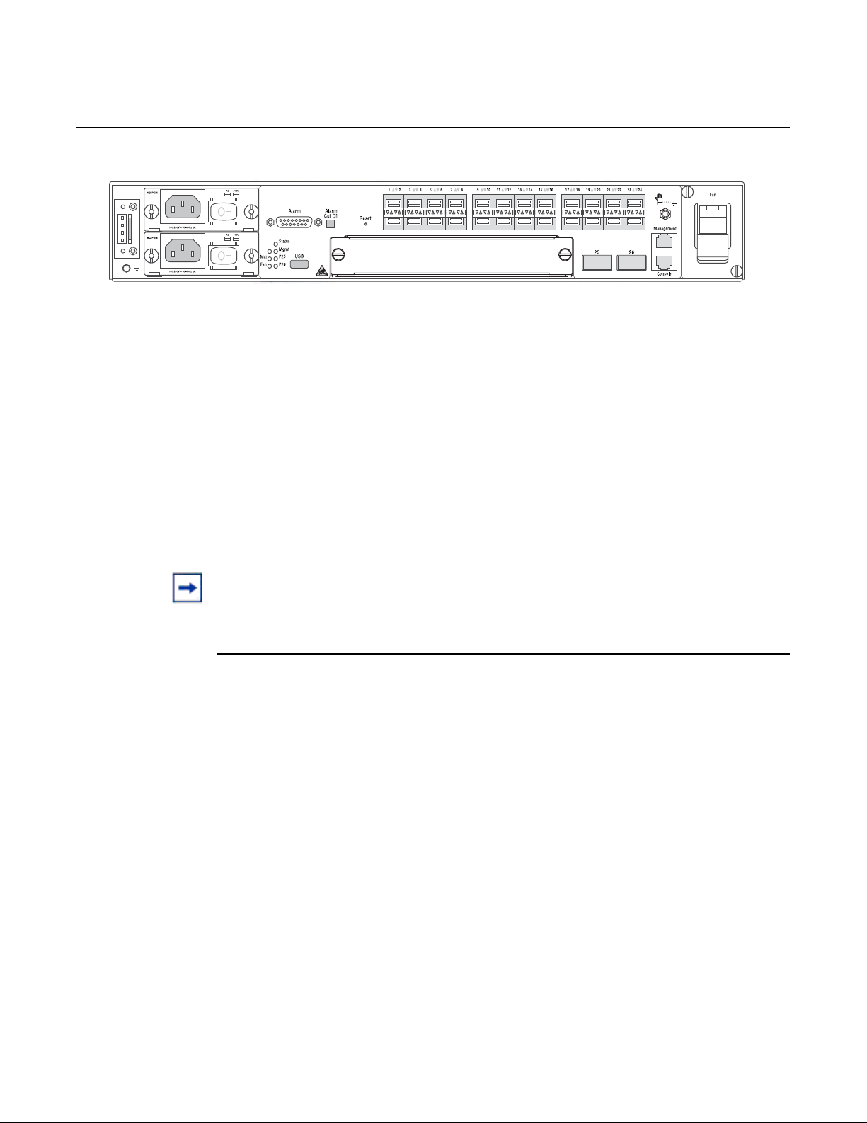
Figure 1 7210 SAS-M 24F Front Panel
7210 SAS-M CHASSIS INSTALLATION GUIDE
The 7210 SAS-M 24F includes the following features:
• 24 100/1000 SFP ports
• one RJ-45 management port for firmware upgrade or system management
• one RJ-45 console (RS-232 interface) connector for device management
• embedded SR OS
• compact size: 1.5 RU height, 19 in. (48.26 cm) rack-mountable metal
enclosure, 10 in. (25.4 cm) depth (ETSI)
14
3HE 10089 AAAA TQZZA Edition 01 Issue: 07
7210 SAS-M CHASSIS INSTALLATION GUIDE System Overview
Crit
SR72029
Figure 2 7210 SAS-M 24F 2XFP (ETR) Front Panel
The 7210 SAS-M 24F 2XFP and 7210 SAS-M 24F 2XFP ETR include the following
features:
• 24 100/1000 SFP ports and two 10G XFP ports
• one RJ-45 management port for firmware upgrade or system management
• one RJ-45 console (RS-232 interface) connector for device management
• 7210 SAS-M 24F 2XFP ETR version supports extended temperature range
• embedded SR OS
• compact size: 1.5 RU height, 19 in. (48.26 cm) rack-mountable metal
enclosure, 10 in. (25.4 cm) depth (ETSI)
Note: Except for the labeling, the 7210 SAS-M 24F 2XFP and 7210 SAS-M 24F 2XFP ETR
chassis are identical in terms of front panel appearance.
Issue: 07 3HE 10089 AAAA TQZZA Edition 01 15

System Overview
2.2 Switch Architecture
2.2.1 Network Management Options
7210 SAS-M CHASSIS INSTALLATION GUIDE
The 7210 SAS-M employs a wire-speed, non-blocking switching fabric. This permits
simultaneous wire-speed transport of multiple packets at low latency on all ports. The
switch also features full-duplex capability on all ports, that effectively doubles the
bandwidth of each connection.
The 7210 SAS-M contains a comprehensive array of LEDs for at-a-glance monitoring
of network and port status. It also includes a management agent that enables you to
configure or monitor your switch using its CLI, or by using SNMP applications.
To manage the switch, you can make a direct connection to the console port (out-ofband Ethernet management port) or you can manage it by using a network
connection (in-band SFP or XFP ports) using Telnet/SSH or SNMP-based network
management software.
The management port provides a dedicated management channel that operates
outside of the data transport network. This makes it possible to reconfigure or
troubleshoot the switch over either a local or remote connection to the management
port when using the data channel is not possible or deemed insecure.
16
3HE 10089 AAAA TQZZA Edition 01 Issue: 07

7210 SAS-M CHASSIS INSTALLATION GUIDE System Overview
2.3 Features
The 7210 SAS-M includes the following features:
• wire speed, non-blocking, service-aware MPLS switch
• 24 100/1000 SFP ports are available on the 7210 SAS-M
• two 10G XFP ports are available on the 7210 SAS-M 24F 2XFP and 7210
SAS-M 24F 2XFP ETR
• 7210 SAS-M 24F 2XFP ETR supports an extended temperature range.
• powered by SR OS
• Per-service quality of service (QoS) with up to eight levels of class-based
queuing per port
• Per-service OAM toolkit with IEEE 802.1ag, IEEE 802.3ah and local service
mirroring
• supports NULL and Dot1Q access SAPs
• dual homed connections uplinks to separate aggregation devices
• flexible deployment options with support for mesh and ring topologies
• MEF 9 and MEF 14 certified platform
• managed by the 5620 SAM
• provides four isolated alarm inputs and two dry contacts that relay outputs
through a
DB-15 interface on the front panel
• hot-swappable, redundant, load-sharing AC or DC power and fan modules
2.3.1 Connectivity
The 7210 SAS-M includes the following connectivity features:
• 100/1000 fiber-optic SFP ports.
• 10G XFP ports on 7210 SAS-M 24F 2XFP and 7210 SAS-M 24F 2XFP ETR
only
• IEEE 802.3-2005 Ethernet, Fast Ethernet, Gigabit Ethernet, and Ten-Gigabit
(only on 7210 SAS-M 24F 2XFP and 7210 SAS-M 24F 2XFP ETR)
compliance ensures compatibility with standards-based network cards and
switches from any vendor.
Issue: 07 3HE 10089 AAAA TQZZA Edition 01 17
System Overview
Crit
1 4 6 7 9 10 12
2b
2a
3 5 8 11
SR72001
2.4 Hardware Description
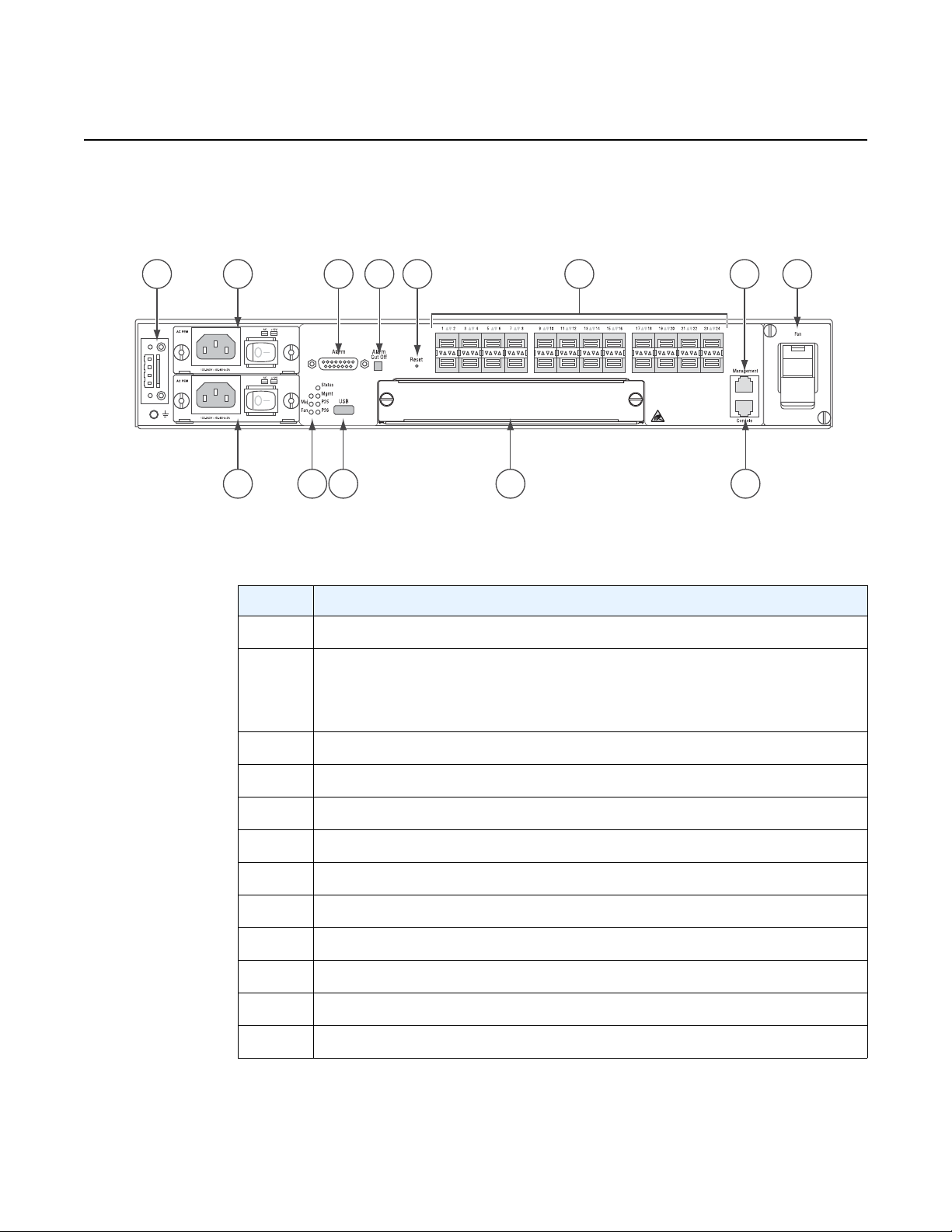
Figure 3 7210 SAS-M 24F Front Panel
7210 SAS-M CHASSIS INSTALLATION GUIDE
Table 1 7210 SAS-M Front Panel Features
Key Description
1 Ground and DC power connection
2 Power trays
2a — power tray A
2b — power tray B
3LEDs
4 Alarm connector
5 USB port
6 Alarm cut off button
7 Reset button
8 Expansion slot
9 100/1000 SFP port LEDs
10 Management port
11 Console port
18
12 Fan tray
3HE 10089 AAAA TQZZA Edition 01 Issue: 07
7210 SAS-M CHASSIS INSTALLATION GUIDE System Overview
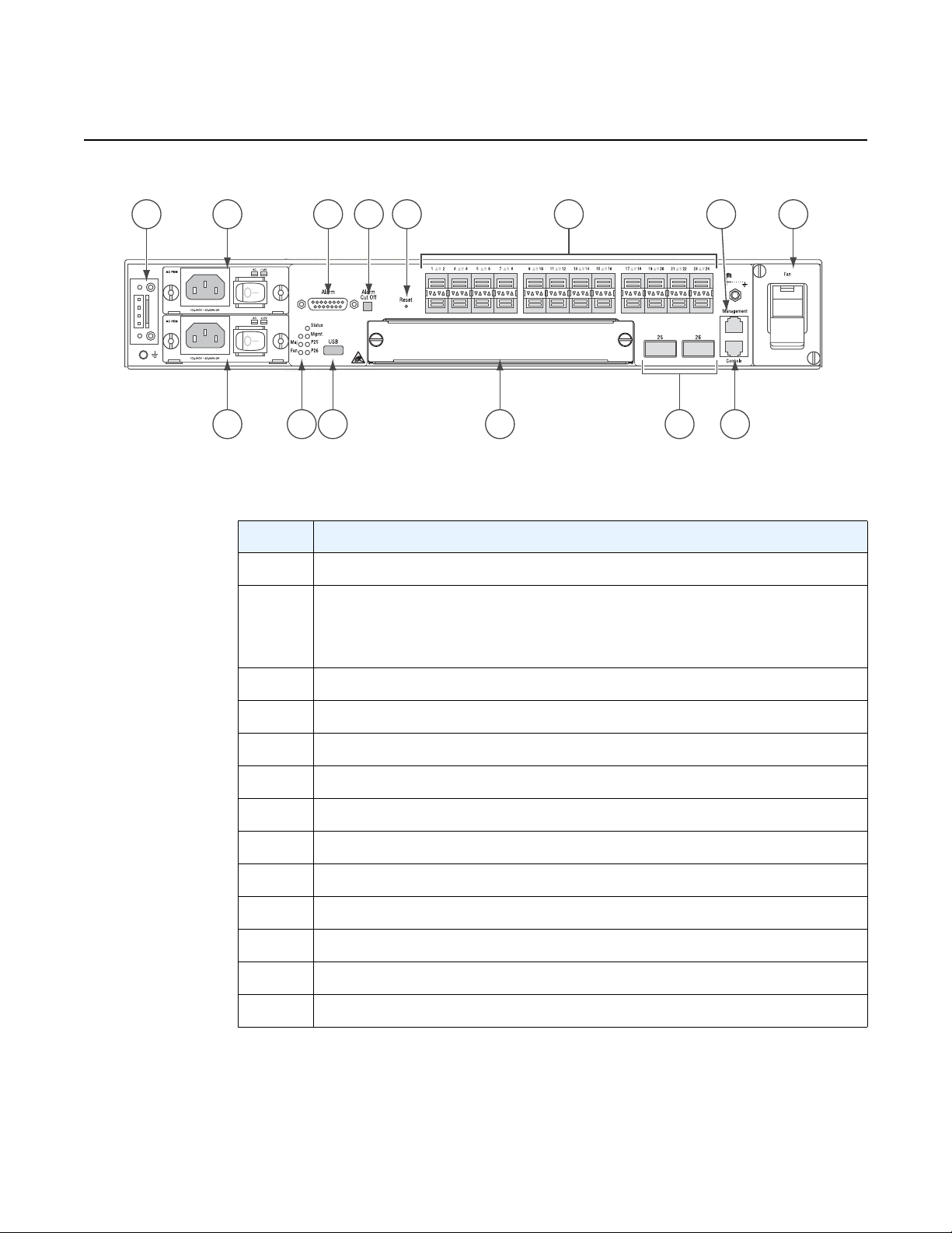
Figure 4 7210 SAS-M 24F 2XPF (ETR) Front Panel
1 4 6 7 9 13
2a
2b
11
Crit
3 5 8 1210
SR72029A
Table 2 7210 SAS-M 24F XFP (ETR) Front Panel Features
Key Description
1 Ground and DC power connection
2 Power trays
2a — power tray A
2b — power tray B
3LEDs
4 Alarm connector
5 USB port
6 Alarm cut off button
7 Reset button
8 Expansion slot
9 100/1000 SFP port LEDs
10 XFP ports
11 Management port
12 Console port
13 Fan tray
Issue: 07 3HE 10089 AAAA TQZZA Edition 01 19

System Overview
2.4.1 Ethernet Interfaces
2.4.1.1 Management Port
7210 SAS-M CHASSIS INSTALLATION GUIDE
The 7210 SAS-M provides 24 100/1000 SFP ports. Each port can be used for a direct
connection to a subscriber’s customer premises equipment (CPE), or as an uplink to
another aggregation node. The 7210 SAS-M supports 10/100/1000 Base-T copper
SFPs. In addition, the 7210 SAS-M 24F 2XFP and 7210 SAS-M 24F 2XFP ETR
variants support two 10G XFP ports. This port can serve as a network uplink to
another aggregation node or as a direction to a subscriber's CPE.
The management port provides a dedicated management interface that is
segregated from data traffic crossing the other ports.
2.4.2 Console Port
The console port uses an RJ-45 connector with serial pin assignments (see Table 11)
that enables a connection to a terminal for performing switch monitoring and
configuration operations. The terminal may be a PC or workstation that is running
terminal emulation software, or a terminal configured as a Data Terminal Equipment
(DTE) connection. A null-modem wired serial cable is supplied with the switch for
connecting to this interface.
The serial port configuration requirements are as follows:
• default baud rate — 115200 bps
• character size — 8 characters
• parity — none
• stop bits — 1
• data bits — 8
• flow control — none
20
3HE 10089 AAAA TQZZA Edition 01 Issue: 07
7210 SAS-M CHASSIS INSTALLATION GUIDE System Overview
2.4.3 Alarm Interface Port
The alarm interface port is a DB15 connector that supports a critical alarm output, a
major alarm output, and four alarm inputs. When the system detects a critical or
major issue, the CPU will cause the alarm relay to issue the alarm output and turn on
the critical or major alarm LED. If you push the alarm cutoff (ACO) button, the relay
will be released but the LED will stay on until the alarm is cleared.
The system signals the appropriate alarm output for the following events:
• Fan failure — critical alarm is raised.
• Power supply failure — critical alarm is raised. When the faile d power supply
is removed, the critical alarm is cleared and a major alarm is raised.
• Power source failure — critical alarm is raised and the system's status LED
turns amber in color and blinks.
• Chassis temperature threshold exceeded — major alarm is raised.
The system also supports four alarm inputs. The input voltage range is from 24V to
48V. If an alarm input is active, the CPU will process it, output it to the CLI, and issu e
an SNMP trap. An alarm input can also be configured to issue through the
appropriate alarm output pin. Please refer to the System Basics User Guide for more
details on configuring the alarm inputs.
See Table 3 for the alarm interface port pin assignments.
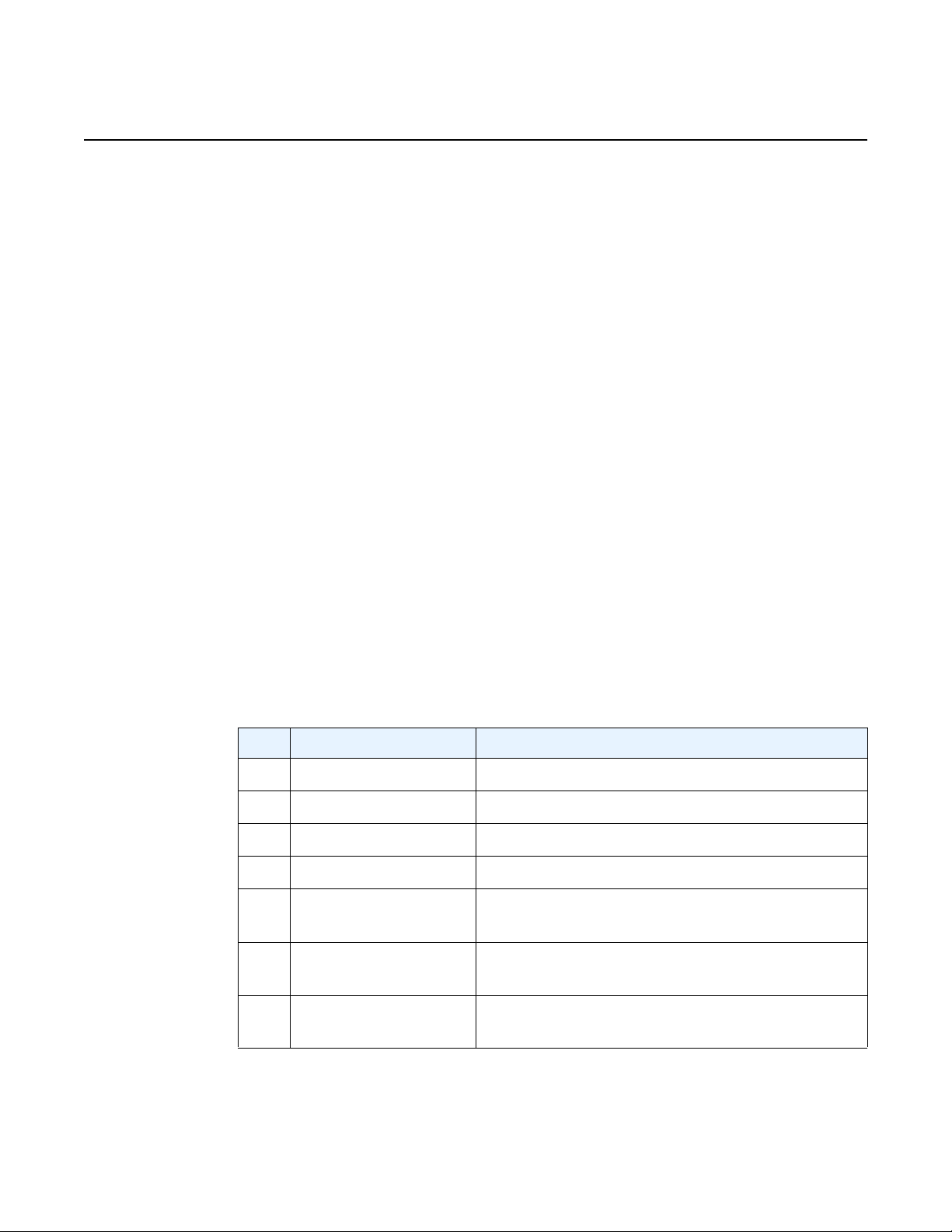
Table 3 Alarm Interface Port Pin Assignments
Pin Name Function
1 CRIT_ALARM_CNTR Common contact for critical alarm relay
2 CRIT_ALARM_NO Normally open during critical alarm state
3 MJR_ALARM_NC Normally closed during major alarm state
4N/C N/C
5 ALARM_IN4_EXT_+ External alarm input 4 (external relay dry contact
closure to pin 12)
6 ALARM_IN3_EXT_+ External alarm input 3 (external relay dry contact
closure to pin 13)
7 ALARM_IN2_EXT_+ External alarm input 2 (external relay dry contact
closure to pin 14)
Issue: 07 3HE 10089 AAAA TQZZA Edition 01 21
System Overview
7210 SAS-M CHASSIS INSTALLATION GUIDE
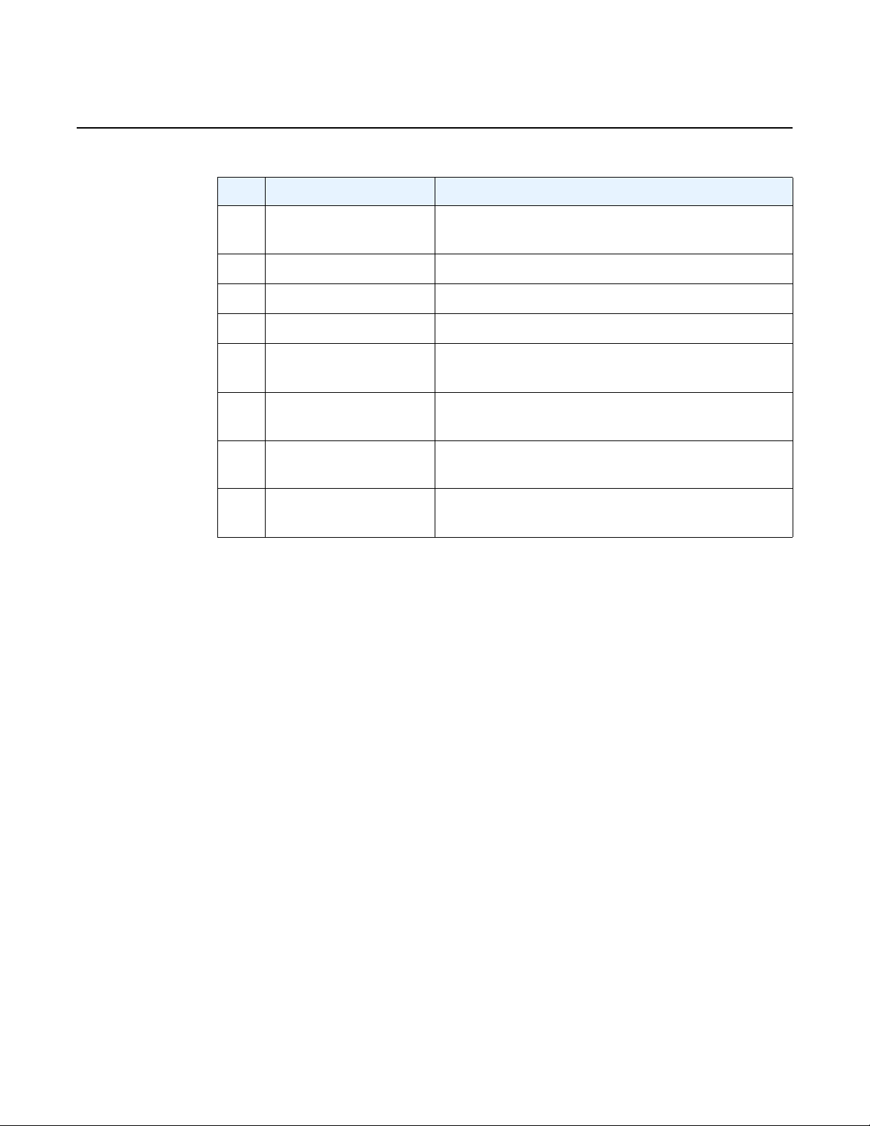
Table 3 Alarm Interface Port Pin Assignments (Continued)
Pin Name Function
8 ALARM_IN1_EXT_+ External alarm input 1 (external relay dry contact
closure to pin 15)
9 CRIT_ALARM_NC Normally closed during critical alarm state
10 MJR_ALARM_CNTR Common contact for major alarm relay
11 MJR_ALARM_NO Normally open during major alarm state
12 ALARM_IN4_EXT_RTNExternal alarm input 4 (external relay dry contact
closure from pin 5)
13 ALARM_IN3_EXT_RTNExternal alarm input 3 (external relay dry contact
closure from pin 6)
14 ALARM_IN2_EXT_RTNExternal alarm input 2 (external relay dry contact
closure from pin 7)
15 ALARM_IN1_EXT_RTNExternal alarm input 1 (external relay dry contact
RTN refers to the negative side of the floating external power supply. This power
supply must not be connected to chassis ground and should be 18 to 50 VDC at 100
ma. Please refer to section 9 for further information.
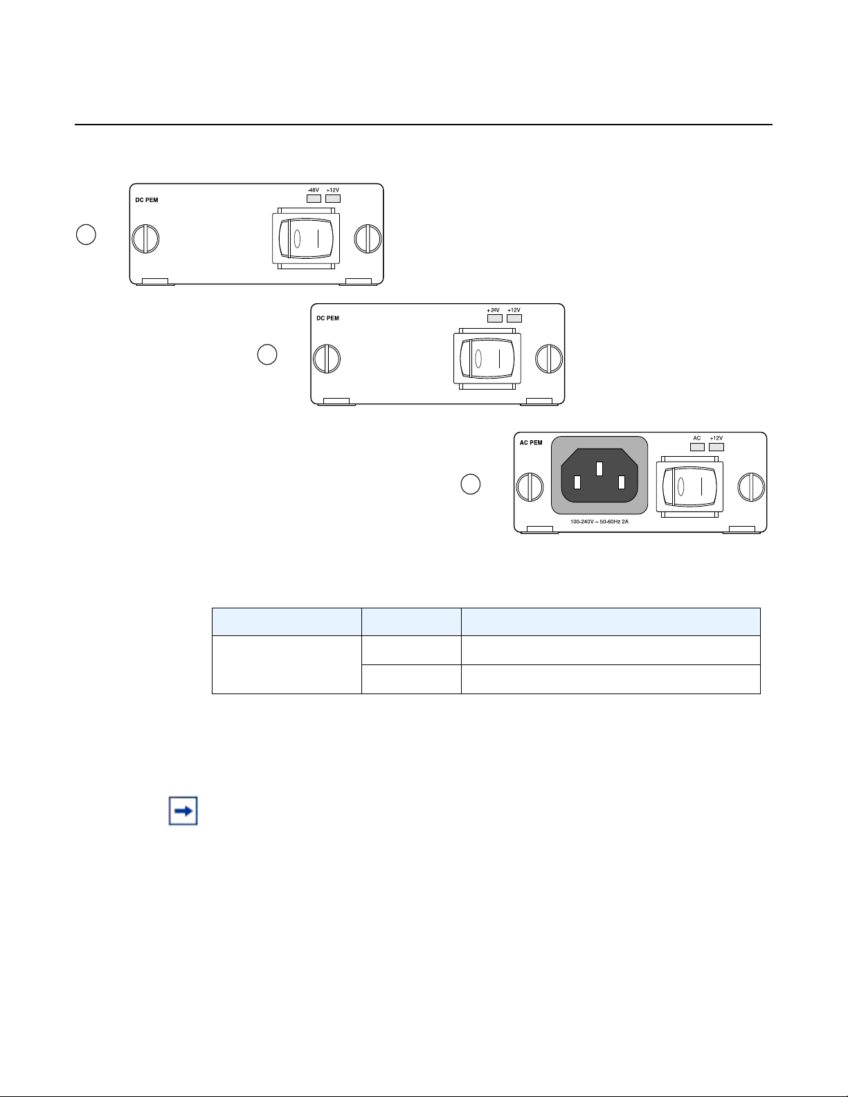
2.4.4 Power Modules
7210 SAS-M 24F 2XFP ETR variant provides three power module options: –48V,
+24V and universal AC. See Figure 5 for an illustration of the power modules.
For specifications on the power modules and external input power requirements, see
section 3.2.4 and section 7.
closure from pin 8)
22
3HE 10089 AAAA TQZZA Edition 01 Issue: 07
7210 SAS-M CHASSIS INSTALLATION GUIDE System Overview
1
3
2
+24V ETR
-48V
Figure 5 AC and DC Power Modules
Table 4 Power Module LEDs
LED Condition Status
AC, –48V,+24,
Green DC or AC power is functioning normally
+12V
Off External power not connected or has failed
The –48V/+24V/AC LEDs on the left indicate the status of external power. The +12V
LED on the right indicates the status of the internal power conversion process.
Note:
• You must use AC and/or DC power modules with your 7210 SAS-M. AC and DC power
module can be used simultaneously.
• The 7210 SAS-M 24F 2XFP ETR variant must use a power module which supports
extended temperature range.
• The +24V DC power module must not be used simultaneously with the –48V DC power
module.
• The +24V DC ETR power module is supported on the all 7210 SAS-M variants
(including non-ETR).
Issue: 07 3HE 10089 AAAA TQZZA Edition 01 23
System Overview
2.4.4.1 DC power source failure detection
7210 SAS-M CHASSIS INSTALLATION GUIDE
The 7210 SAS-M platform provides capability to detect DC power source (–48V or
+24V source) failure. The 7210 SAS-M chassis allows two DC power sources to be
connected to the chassis. If the system detects that the DC power source has failed,
it raises a critical alarm (the Critical LED is lit and the Critical Alarm output pin is
triggered) and the system's status LED turns amber and blinks. The alarm is cleared
if the DC power source is restored. No user configuration is required to enable this
feature. The software enables this feature automatically by detecting the capability
of the hardware platform.
The system has two slots for AC or DC power supplies. It associates the DC power
supply in the top slot with power source feed A (–48V or +24V Ret-A on the chassis)
and the DC power supply in the bottom slot with power source feed B (–48V or
+24VRetB on the chassis). The system detects the failure of power source feed A
only if the DC power supply is plugged into the top slot. Similarly, the system detects
the failure of power source feed B only if the DC power supply is plugged into the
bottom slot. The trap message generated by the system indica tes that there was an
input failure for the power supply associated with the power input feed that failed.
Note:
• New traps must be explicitly enabled by the user and are suppressed by default.
• The power feeds are summed up internally before feeding the power supply units.
Therefore, the DC power supply units will output power even if only one of the power
source feeds are available.
• Please refer to the release notes to determine which software release supports this
feature.
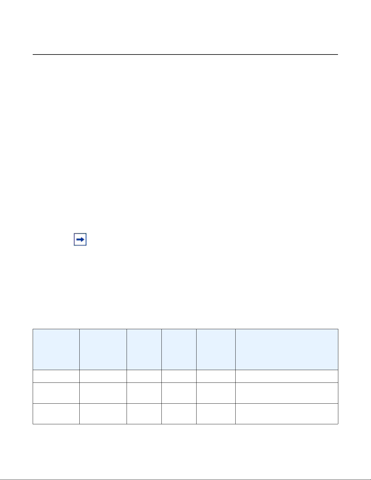
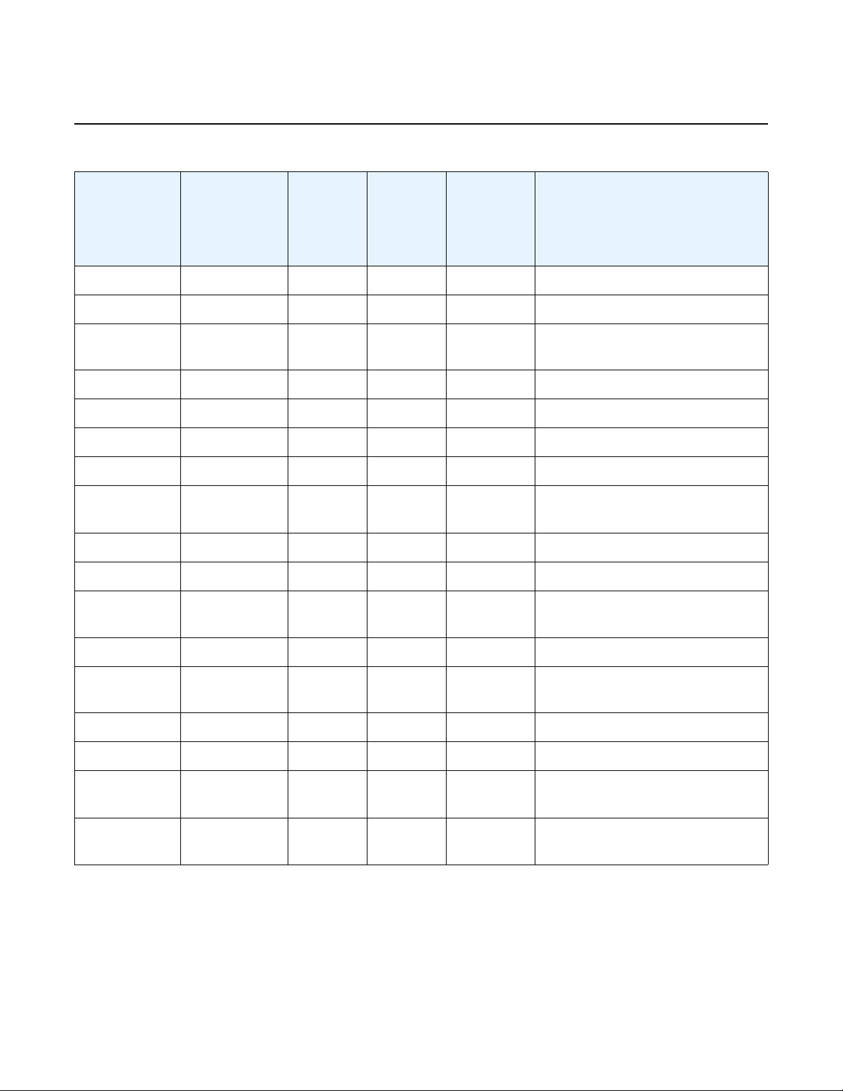
Table 5 lists the conditions under which the system detects a power source failure.
Table 5 Power Source Failure Detection Capability
Power Feed A
(Available/
Failed)
Power Feed B
(Available/
Failed)
Power
Supply in
Top Slot
(PS1)
Power
Supply in
Bottom
Slot
(PS2)
Alarm
Generated
(Yes/No)
Notes
Available Available DC DC No —
Available Failed DC DC Yes PS2 input failure / PS2 output
OK
Failed Available DC DC Yes PS1 input failure / PS1 output
OK
24
3HE 10089 AAAA TQZZA Edition 01 Issue: 07
7210 SAS-M CHASSIS INSTALLATION GUIDE System Overview
Table 5 Power Source Failure Detection Capability (Continued)
Power Feed A
(Available/
Failed)
Power Feed B
(Available/
Failed)
Power
Supply in
Top Slot
(PS1)
Power
Supply in
Bottom
Slot
(PS2)
Alarm
Generated
(Yes/No)
Notes
Failed Failed DC DC — No power to system
Available Available None DC No —
Available Failed None DC Yes PS2 input failure / PS2 output
OK
Failed Available None DC No Input failure / Not detected
Failed Failed None DC — No power to system
Available Available DC None No —
Available Failed DC None No Input failure / Not detected
Failed Available DC None Yes PS1 input failure / PS1 output
OK
Failed Failed DC None — No power to system
Available Available AC DC No —
Available Failed AC DC Yes PS2 input failure / PS2 output
OK
Failed Available AC DC No Input failure / Not detected
Failed Failed AC DC Yes PS2 input failure / PS2 output
failure
Available Available DC AC No —
Available Failed DC AC No Input failure / Not detected
Failed Available DC AC Yes PS1 input failure / PS1 output
OK
Failed Failed DC AC Yes PS1 input failure / PS1 output
OK
Issue: 07 3HE 10089 AAAA TQZZA Edition 01 25
System Overview
2.4.5 USB Port
The USB port is reserved for future use.
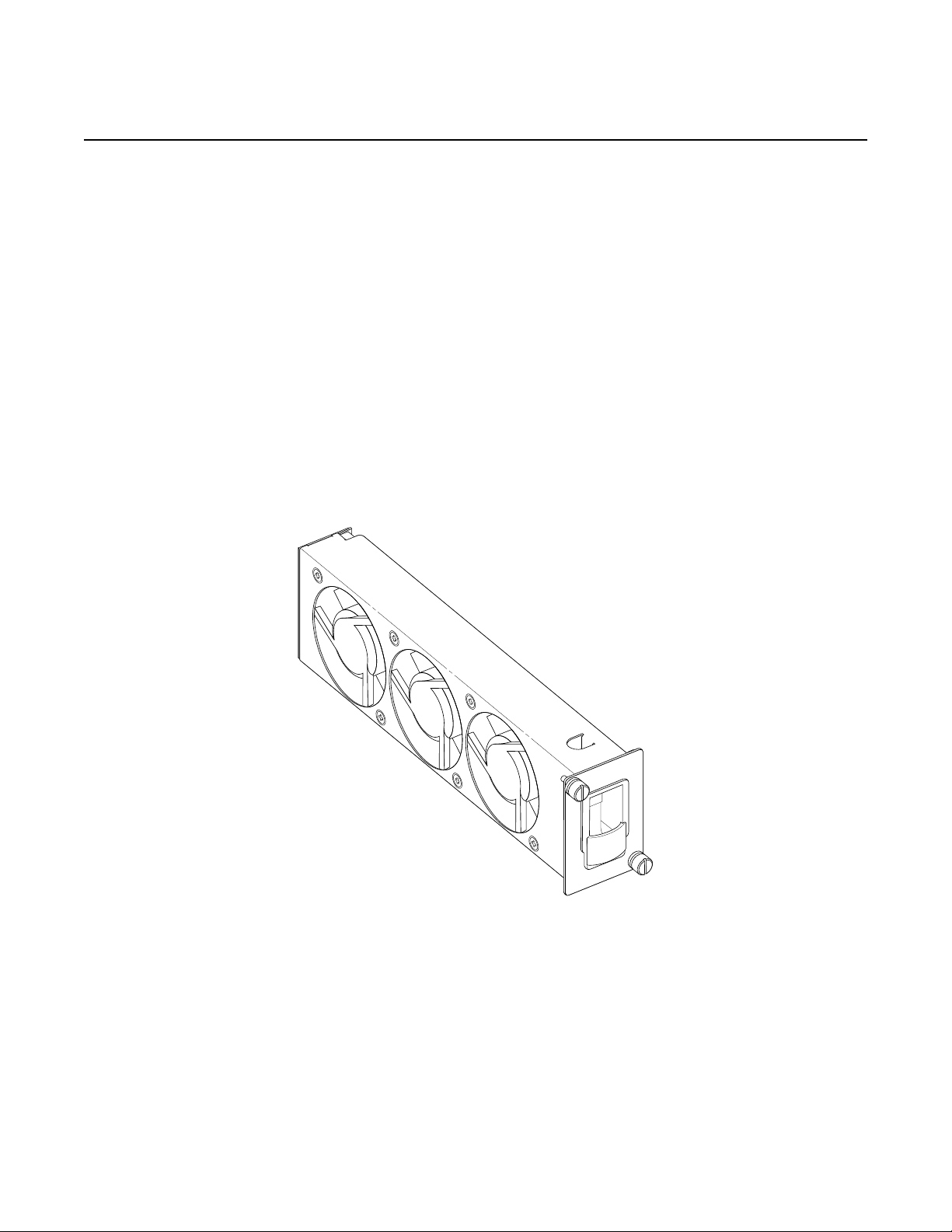
2.4.6 Fan Tray
A hot-swappable fan tray on the right side of the front panel contains three fans that
provide cooling for the chassis. See Figure 6 for an illustration of the fan tray.
The fans are controlled by the system software, and their speed is set according to
the environmental temperature surrounding the switch. Allow at least 3 in. (7.62 cm)
of clearance on the side of the rack to ensure proper airflow intake cooling system.
The fan trays must be in place before the chassis is powered on.
Figure 6 Fan Tray
7210 SAS-M CHASSIS INSTALLATION GUIDE
26
The fan tray also contains an air filter. The filter tray must always be installed while
the chassis is powered up. The air filter prevents large particles, debris, and dust
from entering and circulating through the system. Inspect your air filter month ly and
replace it when accumulated dust is present.
3HE 10089 AAAA TQZZA Edition 01 Issue: 07
7210 SAS-M CHASSIS INSTALLATION GUIDE System Overview
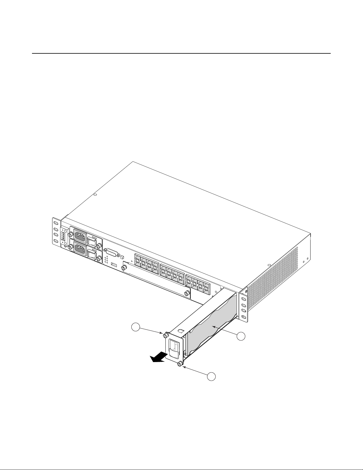
SR72027
1
1
2
To inspect and remove your air filter, see Figure 7 and perform the following steps:
Step 1. Loosen the captive screws on the fan tray (Figure 7 item 1).
Step 2. Carefully remove the fan tray from the router chassis and remove the air
filter (Figure 7 item 2) to inspect it and replace it (3HE06340AA), if
necessary.
Step 3. After inspecting and replacing the air filter, replace it in the fan tray so that
the edge of the air filter is flush with the rear of the fan tray.
Step 4. Replace the fan tray and tighten the captive screws.
Figure 7 Removing and Replacing the Fan Tray and Air Filter
Issue: 07 3HE 10089 AAAA TQZZA Edition 01 27
System Overview
Crit
32 54
1 6
SR72025
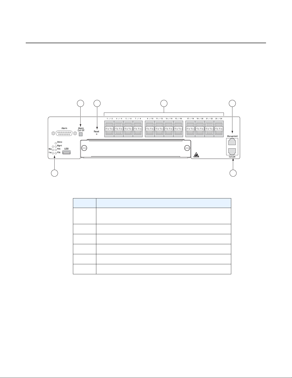
2.4.7 System LEDs and Buttons
The LEDs are located on the front panel and the power module trays. See Figure 8
for the location of the system LEDs and buttons, Table 6 for key descriptions, and
Table 7 for alarm descriptions.
Figure 8 System LEDs and Buttons
7210 SAS-M CHASSIS INSTALLATION GUIDE
Table 6 7210 SAS-M System LEDs and Buttons
Key Description
1 Alarm LEDs and 10G port LEDs for 7210 SAS-M 24F
2XFP and 7210 SAS-M 24F 2XFP ETR only
2 Alarm Cut Off button
3 Reset button
4 100/1000 SFP port LEDs
5 Management port
6 Console port
28
3HE 10089 AAAA TQZZA Edition 01 Issue: 07
 Loading...