

Nokia 7210 SAS-M, 7210 SAS-M 24F, 7210, 7210 SAS-M 24F2XFP, 7210 24F 2XFP ETR Installation Manual
Page 1

7210 SAS-M CHASSIS INSTALLATION GUIDE
7210 SERVICE ACCESS
SWITCH
7210 SAS-M CHASSIS
INSTALLATION GUIDE
3HE 10089 AAAA TQZZA Edition 01
Issue: 07
August 2016
Nokia — Proprietary and confidential.
Use pursuant to applicable agreements..
Page 2

7210 SAS-M CHASSIS INSTALLATION GUIDE
Nokia is a registered trademark of Nokia Corporation. Other products and company
names mentioned herein may be trademarks or tradenames of their respective
owners.
All specifications, procedures, and information in this document are subject to
change and revision at any time without notice. The information contained herein is
believed to be accurate as of the date of publication. Nokia provides no warranty,
express or implied, regarding its contents. Users are fully responsible for application
or use of the documentation.
© 2016 Nokia. All rights reserved.
Contains proprietary/trade secret information which is the property of Nokia and must
not be made available to, or copied or used by anyone outside Nokia without its
written authorization. Not to be used or disclosed except in accordance with
applicable agreements.
2
3HE 10089 AAAA TQZZA Edition 01 Issue: 07
Page 3

7210 SAS-M CHASSIS INSTALLATION GUIDE
Table of Contents
1 Preface............................................................................ 11
1.1 About This Manual.....................................................................11
1.1.1 Warnings and Notes............................... ... ... .... .........................11
1.1.2 Audience....................................................................................11
1.1.3 Symbols and Labels..................................................................12
1.1.4 Technical Support...................................................................... 12
2 System Overview........................................................... 13
2.1 7210 SAS-M Introduction and Features....................................14
2.2 Switch Architecture........................................... ... ... ...................16
2.2.1 Network Management Options..................................................16
2.3 Features ....................................................................................17
2.3.1 Connectivity...............................................................................17
2.4 Hardware Description................................................................ 18
2.4.1 Ethernet Interfaces....................................................................20
2.4.1.1 Management Port ..................................................................... 20
2.4.2 Console Port .............................................................................20
2.4.3 Alarm Interface Port................................................................... 21
2.4.4 Power Modules..........................................................................22
2.4.4.1 DC power source failure detection ............................................ 24
2.4.5 USB Port ................................ ... ... .... ... ... ... ... .... .........................26
2.4.6 Fan Tray.................................................................................... 26
2.4.7 System LEDs and Buttons......................................................... 28
2.4.8 System and Port LEDs..............................................................29
2.4.9 Port LEDs.................................. ... .... ... ... ... ... .............................29
2.4.10 System Buttons and Switches................... ... .... ... ......................31
3 Installing the Chassis.................................................... 33
3.1 Site Preparation.........................................................................34
3.1.1 Selecting a Site ......................................................................... 34
3.1.2 Ethernet Cabling........................................................................34
3.2 Installing Your Switch....................................... ... ... ... .... ... ... ... ... 35
3.2.1 Rack Mounting ............................. .... ... ... ... ... .... .........................35
3.2.2 Desktop or Shelf Mounting ........................................... ... ... ... ... 37
3.2.3 Grounding the Chassis ............................................................. 38
3.2.4 Connecting to a Power Source ................................................. 40
3.2.4.1 Connecting to AC Power........................................ ... ................40
3.2.4.2 Connecting to DC Power .......................................................... 41
3.2.4.3 Connecting to the Console Port ................................................44
Issue: 07 3HE 10089 AAAA TQZZA Edition 01 3
Page 4

7210 SAS-M CHASSIS INSTALLATION GUIDE
4 Transceivers................................................................... 45
4.1 Warnings and Notes............................... ... ... .... .........................46
4.2 Installation Preparation..............................................................47
4.2.1 Locking and Release Mechanisms............................................47
4.2.2 Installing SFP/XFPs.......................... ... ... ... ... .... ... ... ... .... ............47
4.2.3 Removing and Replacing SFP/XFPs.........................................48
5 Configuring the System ................................................ 49
5.1 Diagnostics................................................................................50
5.1.1 Post Installation Status .................... ... ... ... ... .............................50
5.2 Initializing the System and Downloading Software....................51
5.2.1 Booting in the Lab...................................................................... 51
5.2.1.1 Booting Using the Image on Flash ............................................52
5.2.1.2 Booting From the Network.........................................................54
5.2.1.3 Using Out-of-Band Port to Boot from the Network: ................... 60
5.2.1.4 Downloading the TiMOS Software to the Internal Flash............ 62
5.3 Establishing Router Connections ..............................................65
5.3.1 Console Connection.................................................................. 65
5.3.2 Telnet Connection .....................................................................66
5.3.2.1 Running Telnet....................................... ... ... .... ... ... ...................67
5.4 Restarting the Router ................................................................ 67
6 Troubleshooting ............................................................ 69
6.1 Diagnosing Switch Indicators .................................................... 70
6.2 Power and Cooling Problems....................................................71
6.3 Installation ................................................................................ 71
6.4 In-Band Access ......... ... ... .... ... ... ... .... ... ......................................72
7 Specifications ................................................................ 73
7.1 Specifications ............................................................................74
7.1.1 Regulatory Compliance Standards and Certifications...............75
8 Pin Assignments............................................................ 79
8.1 Management Port Pin Assignments..........................................80
8.2 Console Port Pin Assignment ...................................................81
4
3HE 10089 AAAA TQZZA Edition 01 Issue: 07
Page 5

7210 SAS-M CHASSIS INSTALLATION GUIDE
9 Alarm Pin Assignments ................................................ 83
9.1 Alarm Port Pin Assignments......................................................84
10 Installation Site Assessment ....................................... 87
10.1 Geographical Location...............................................................87
10.2 Installation Site Type.................................................................88
10.2.1 Room.........................................................................................88
10.2.2 Cabinet......................................................................................89
10.3 Site Influences........................................................................... 89
10.4 Site Assessment Checklists ......................................................90
10.4.1 Seasonal Influences.. ... ... .... ...................................................... 90
10.4.2 Local Risk Factors..................................................................... 91
10.4.3 Specific Characteristics of the Installation Site..........................92
Issue: 07 3HE 10089 AAAA TQZZA Edition 01 5
Page 6

7210 SAS-M CHASSIS INSTALLATION GUIDE
6
3HE 10089 AAAA TQZZA Edition 01 Issue: 07
Page 7

7210 SAS-M CHASSIS INSTALLATION GUIDE
List of Tables
2 System Overview........................................................... 13
Table 1 7210 SAS-M Front Panel Features ........................................... 18
Table 2 7210 SAS-M 24F XFP (ETR) Front Panel Features..................19
Table 3 Alarm Interface Port Pin Assignments ......................................21
Table 4 Power Module LEDs..................................................................23
Table 5 Power Source Failure Detection Capability .............................. 24
Table 6 7210 SAS-M System LEDs and Buttons...................................28
Table 7 System and Port Status LEDs...................................................29
Table 8 Port LEDs..................................... .... ... ......................................29
Table 9 Port LED Key Descriptions .......................................................30
Table 10 Front Panel Buttons and Switches ............................................31
3 Installing the Chassis.................................................... 33
Table 11 Serial Port Pin Assignment .......................................................44
5 Configuring the System ................................................ 49
Table 12 Console Configuration Parameter Values................................. 65
6 Troubleshooting ............................................................ 69
Table 13 Troubleshooting ........................................................................ 70
7 Specifications ................................................................ 73
Table 14 7210 SAS-M Specifications ......................................................74
Table 15 Compliance Standards and Certifications ................................ 75
8 Pin Assignments............................................................ 79
Table 16 10/100 Base-Tx MDI and MDI-X Port Pin Assignments............80
Table 17 Serial Cable Wiring .................................................................. 81
9 Alarm Pin Assignments ................................................ 83
Table 18 Alarm Interface Port Pin Assignments ......................................84
10 Installation Site Assessment ....................................... 87
Table 19 Checklist 1: Seasonal Influences...............................................90
Table 20 Checklist 2: Local Risk Factors ................................................91
Table 21 Checklist 3: Specific Characteristics of the Installation Site .....92
Issue: 07 3HE 10089 AAAA TQZZA Edition 01 7
Page 8

7210 SAS-M CHASSIS INSTALLATION GUIDE
8
3HE 10089 AAAA TQZZA Edition 01 Issue: 07
Page 9

7210 SAS-M CHASSIS INSTALLATION GUIDE
List of Figures
2 System Overview........................................................... 13
Figure 1 7210 SAS-M 24F Front Panel ................................................... 14
Figure 2 7210 SAS-M 24F 2XFP (ETR) Front Panel...............................15
Figure 3 7210 SAS-M 24F Front Panel ................................................... 18
Figure 4 7210 SAS-M 24F 2XPF (ETR) Front Panel...............................19
Figure 5 AC and DC Power Modules ............................. ... ... ... .... ... ... ... ... 23
Figure 6 Fan Tray ................................................................................... 26
Figure 7 Removing and Replacing the Fan Tray and Air Filter................ 27
Figure 8 System LEDs and Buttons......................................................... 28
Figure 9 SFP Port LEDs .........................................................................30
3 Installing the Chassis.................................................... 33
Figure 10 Attaching the Brackets............................................................... 35
Figure 11 Installing the Switch in a Rack ......................... ......................... 36
Figure 12 Attaching the Adhesive Feet .................................. ... .... ... ... ... ... 37
Figure 13 Connecting to a –48 VDC Power Source.................................. 42
Figure 14 Connecting to a +24 VDC Power Source.................. .... ... ... ...... 43
5 Configuring the System ................................................ 49
Figure 15 7210 SAS-M Boot Process........................................................ 51
9 Alarm Pin Assignments ................................................ 83
Figure 16 DB-15 Alarm Connector ............................................................ 84
Figure 17 Alarm Input Connection Diagram ..............................................86
Issue: 07 3HE 10089 AAAA TQZZA Edition 01 9
Page 10

7210 SAS-M CHASSIS INSTALLATION GUIDE
10
3HE 10089 AAAA TQZZA Edition 01 Issue: 07
Page 11

7210 SAS-M CHASSIS INSTALLATION GUIDE Preface
1 Preface
1.1 About This Manual
This guide provides site preparation recommendations, step-by-step procedures to
rack mount the Nokia 7210 Service Access Switch MPLS (SAS-M), and instructions
to install and configure the system software.
This guide hereafter refers to all the variants (7210 SAS-M 24F, 7210 SAS-M 24F
2XFP, and 7210 SAS-M 24F 2XFP ETR) as 7210 SAS-M. Any differences amongst
the variants are called out separately, as applicable.
Each 7210 SAS-M switch is shipped with rack-mounting brackets, power cord (AC
only), and rubber feet.
1.1.1 Warnings and Notes
Observe the warnings and notes provided in each chapter to avoid injury or
equipment damage during installation and maintenance. Follow the safety
procedures and guidelines when working with and near electrical equipment.
1.1.2 Audience
This guide is intended for network installers and system administrators who are
responsible for installing, configuring, or maintaining networks. This guide assumes
that you are familiar with electronic and networking technologies.
Issue: 07 3HE 10089 AAAA TQZZA Edition 01 11
Page 12
Preface
CLASS 1 LASER PRODUCT
7210 SAS-M CHASSIS INSTALLATION GUIDE
1.1.3 Symbols and Labels
The following symbols and labels are contained in this guide:
Danger: This symbol warns that incorrect handling and installation could result in
bodily injury. An electric shock hazard could exist. Before you begin work on this
equipment, be aware of hazards involving electrical circuitry, be familiar with
networking environments, and observe accident prevention procedures.
Warning: This symbol warns that incorrect handling and installation could result in
equipment damage or loss of data.
Caution: This symbol warns that incorrect handling may reduce the component or
system performance.
Note: This symbol provides additional operational information.
This label indicates that only approved Class 1 replaceable laser
transceivers should be used with this product.
1.1.4 Technical Support
If you purchased a service agreement for your 7210 SAS-M and related products
from a distributor or authorized reseller, contact the technical support staff for that
distributor or reseller for assistance. If you purchased an Nokia service agreement,
contact technical assistance at:
Customer Documentation Feedback
12
3HE 10089 AAAA TQZZA Edition 01 Issue: 07
Page 13

7210 SAS-M CHASSIS INSTALLATION GUIDE System Overview
2 System Overview
This chapter describes the 7210 SAS-M features and includes the following sections:
• 7210 SAS-M Introduction and Features, section 2.1
• Switch Architecture, section 2.2
• Features, section 2.3
• Hardware Description, section 2.4
Issue: 07 3HE 10089 AAAA TQZZA Edition 01 13
Page 14

System Overview
Crit
SR72001A
2.1 7210 SAS-M Introduction and Features
The 7210 SAS-M is a multilayer service-aware MPLS-capable switch. The switch is
available as two variants, as follows:
• 7210 SAS-M 24F with support for up to 24 100/1000 SFP ports; see Figure 1
• 7210 SAS-M 24F 2XFP and 7210 SAS-M 24F 2XFP ETR with support for up
to 24 100/1000 SFP ports and up to two XFP (10G) ports; see Figure 2
The 7210 SAS-M and its variants have one 10/100 Base-Tx management port for
dedicated management access.
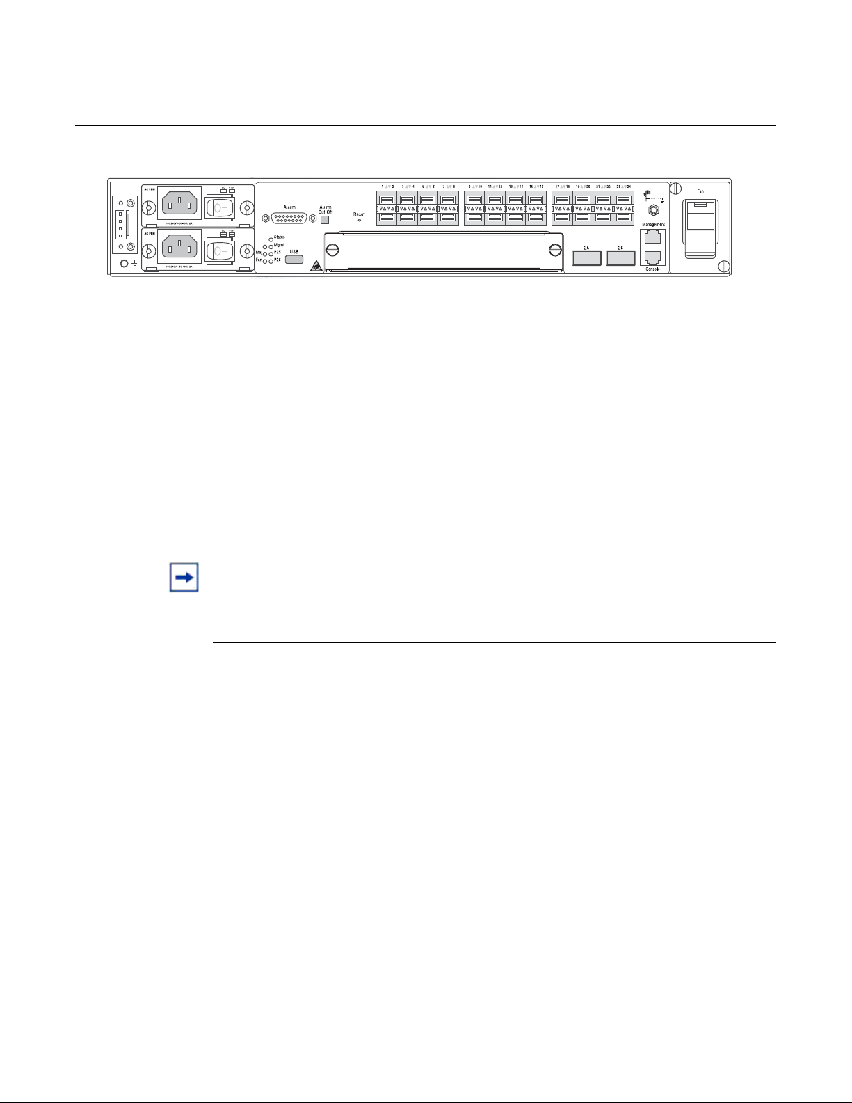
Figure 1 7210 SAS-M 24F Front Panel
7210 SAS-M CHASSIS INSTALLATION GUIDE
The 7210 SAS-M 24F includes the following features:
• 24 100/1000 SFP ports
• one RJ-45 management port for firmware upgrade or system management
• one RJ-45 console (RS-232 interface) connector for device management
• embedded SR OS
• compact size: 1.5 RU height, 19 in. (48.26 cm) rack-mountable metal
enclosure, 10 in. (25.4 cm) depth (ETSI)
14
3HE 10089 AAAA TQZZA Edition 01 Issue: 07
Page 15
7210 SAS-M CHASSIS INSTALLATION GUIDE System Overview
Crit
SR72029
Figure 2 7210 SAS-M 24F 2XFP (ETR) Front Panel
The 7210 SAS-M 24F 2XFP and 7210 SAS-M 24F 2XFP ETR include the following
features:
• 24 100/1000 SFP ports and two 10G XFP ports
• one RJ-45 management port for firmware upgrade or system management
• one RJ-45 console (RS-232 interface) connector for device management
• 7210 SAS-M 24F 2XFP ETR version supports extended temperature range
• embedded SR OS
• compact size: 1.5 RU height, 19 in. (48.26 cm) rack-mountable metal
enclosure, 10 in. (25.4 cm) depth (ETSI)
Note: Except for the labeling, the 7210 SAS-M 24F 2XFP and 7210 SAS-M 24F 2XFP ETR
chassis are identical in terms of front panel appearance.
Issue: 07 3HE 10089 AAAA TQZZA Edition 01 15
Page 16

System Overview
2.2 Switch Architecture
2.2.1 Network Management Options
7210 SAS-M CHASSIS INSTALLATION GUIDE
The 7210 SAS-M employs a wire-speed, non-blocking switching fabric. This permits
simultaneous wire-speed transport of multiple packets at low latency on all ports. The
switch also features full-duplex capability on all ports, that effectively doubles the
bandwidth of each connection.
The 7210 SAS-M contains a comprehensive array of LEDs for at-a-glance monitoring
of network and port status. It also includes a management agent that enables you to
configure or monitor your switch using its CLI, or by using SNMP applications.
To manage the switch, you can make a direct connection to the console port (out-ofband Ethernet management port) or you can manage it by using a network
connection (in-band SFP or XFP ports) using Telnet/SSH or SNMP-based network
management software.
The management port provides a dedicated management channel that operates
outside of the data transport network. This makes it possible to reconfigure or
troubleshoot the switch over either a local or remote connection to the management
port when using the data channel is not possible or deemed insecure.
16
3HE 10089 AAAA TQZZA Edition 01 Issue: 07
Page 17

7210 SAS-M CHASSIS INSTALLATION GUIDE System Overview
2.3 Features
The 7210 SAS-M includes the following features:
• wire speed, non-blocking, service-aware MPLS switch
• 24 100/1000 SFP ports are available on the 7210 SAS-M
• two 10G XFP ports are available on the 7210 SAS-M 24F 2XFP and 7210
SAS-M 24F 2XFP ETR
• 7210 SAS-M 24F 2XFP ETR supports an extended temperature range.
• powered by SR OS
• Per-service quality of service (QoS) with up to eight levels of class-based
queuing per port
• Per-service OAM toolkit with IEEE 802.1ag, IEEE 802.3ah and local service
mirroring
• supports NULL and Dot1Q access SAPs
• dual homed connections uplinks to separate aggregation devices
• flexible deployment options with support for mesh and ring topologies
• MEF 9 and MEF 14 certified platform
• managed by the 5620 SAM
• provides four isolated alarm inputs and two dry contacts that relay outputs
through a
DB-15 interface on the front panel
• hot-swappable, redundant, load-sharing AC or DC power and fan modules
2.3.1 Connectivity
The 7210 SAS-M includes the following connectivity features:
• 100/1000 fiber-optic SFP ports.
• 10G XFP ports on 7210 SAS-M 24F 2XFP and 7210 SAS-M 24F 2XFP ETR
only
• IEEE 802.3-2005 Ethernet, Fast Ethernet, Gigabit Ethernet, and Ten-Gigabit
(only on 7210 SAS-M 24F 2XFP and 7210 SAS-M 24F 2XFP ETR)
compliance ensures compatibility with standards-based network cards and
switches from any vendor.
Issue: 07 3HE 10089 AAAA TQZZA Edition 01 17
Page 18
System Overview
Crit
1 4 6 7 9 10 12
2b
2a
3 5 8 11
SR72001
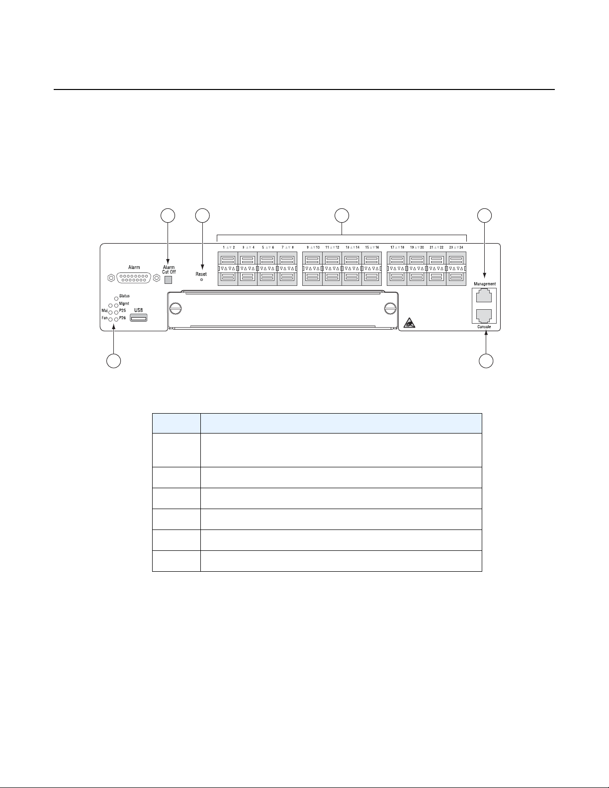
2.4 Hardware Description
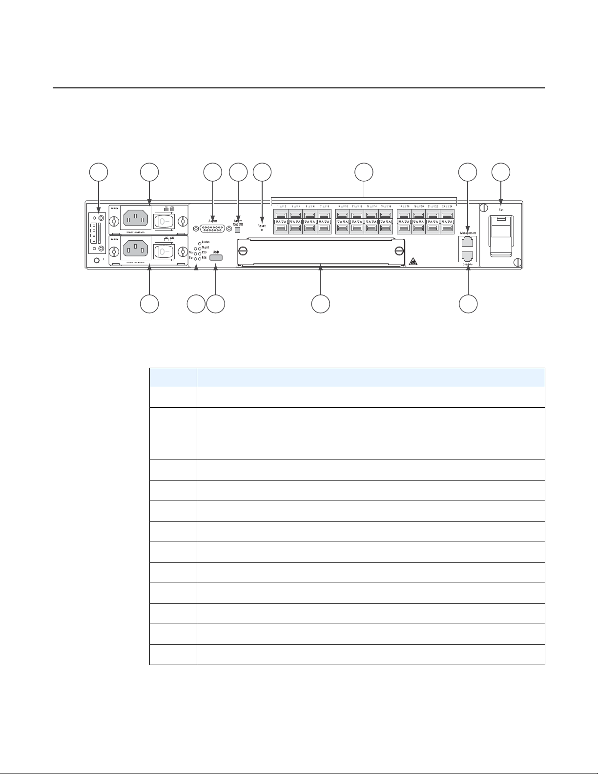
Figure 3 7210 SAS-M 24F Front Panel
7210 SAS-M CHASSIS INSTALLATION GUIDE
Table 1 7210 SAS-M Front Panel Features
Key Description
1 Ground and DC power connection
2 Power trays
2a — power tray A
2b — power tray B
3LEDs
4 Alarm connector
5 USB port
6 Alarm cut off button
7 Reset button
8 Expansion slot
9 100/1000 SFP port LEDs
10 Management port
11 Console port
18
12 Fan tray
3HE 10089 AAAA TQZZA Edition 01 Issue: 07
Page 19
7210 SAS-M CHASSIS INSTALLATION GUIDE System Overview
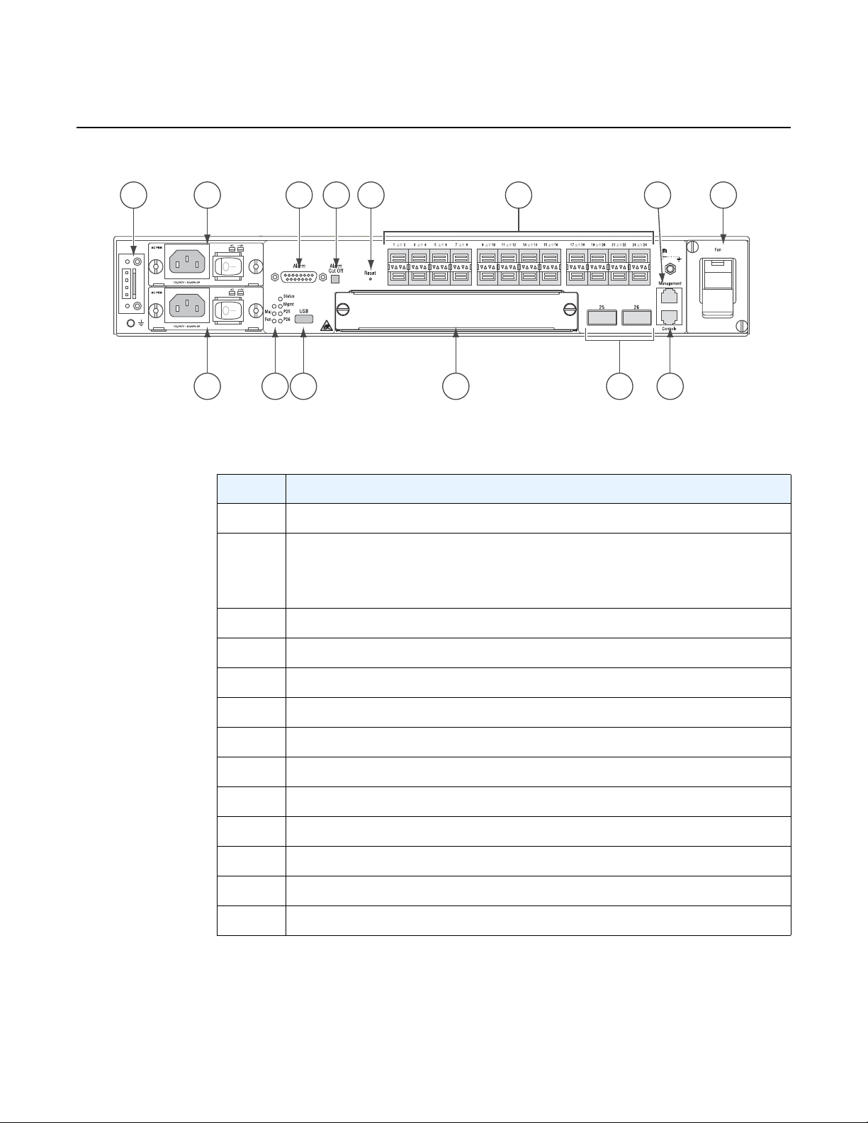
Figure 4 7210 SAS-M 24F 2XPF (ETR) Front Panel
1 4 6 7 9 13
2a
2b
11
Crit
3 5 8 1210
SR72029A
Table 2 7210 SAS-M 24F XFP (ETR) Front Panel Features
Key Description
1 Ground and DC power connection
2 Power trays
2a — power tray A
2b — power tray B
3LEDs
4 Alarm connector
5 USB port
6 Alarm cut off button
7 Reset button
8 Expansion slot
9 100/1000 SFP port LEDs
10 XFP ports
11 Management port
12 Console port
13 Fan tray
Issue: 07 3HE 10089 AAAA TQZZA Edition 01 19
Page 20

System Overview
2.4.1 Ethernet Interfaces
2.4.1.1 Management Port
7210 SAS-M CHASSIS INSTALLATION GUIDE
The 7210 SAS-M provides 24 100/1000 SFP ports. Each port can be used for a direct
connection to a subscriber’s customer premises equipment (CPE), or as an uplink to
another aggregation node. The 7210 SAS-M supports 10/100/1000 Base-T copper
SFPs. In addition, the 7210 SAS-M 24F 2XFP and 7210 SAS-M 24F 2XFP ETR
variants support two 10G XFP ports. This port can serve as a network uplink to
another aggregation node or as a direction to a subscriber's CPE.
The management port provides a dedicated management interface that is
segregated from data traffic crossing the other ports.
2.4.2 Console Port
The console port uses an RJ-45 connector with serial pin assignments (see Table 11)
that enables a connection to a terminal for performing switch monitoring and
configuration operations. The terminal may be a PC or workstation that is running
terminal emulation software, or a terminal configured as a Data Terminal Equipment
(DTE) connection. A null-modem wired serial cable is supplied with the switch for
connecting to this interface.
The serial port configuration requirements are as follows:
• default baud rate — 115200 bps
• character size — 8 characters
• parity — none
• stop bits — 1
• data bits — 8
• flow control — none
20
3HE 10089 AAAA TQZZA Edition 01 Issue: 07
Page 21

7210 SAS-M CHASSIS INSTALLATION GUIDE System Overview
2.4.3 Alarm Interface Port
The alarm interface port is a DB15 connector that supports a critical alarm output, a
major alarm output, and four alarm inputs. When the system detects a critical or
major issue, the CPU will cause the alarm relay to issue the alarm output and turn on
the critical or major alarm LED. If you push the alarm cutoff (ACO) button, the relay
will be released but the LED will stay on until the alarm is cleared.
The system signals the appropriate alarm output for the following events:
• Fan failure — critical alarm is raised.
• Power supply failure — critical alarm is raised. When the faile d power supply
is removed, the critical alarm is cleared and a major alarm is raised.
• Power source failure — critical alarm is raised and the system's status LED
turns amber in color and blinks.
• Chassis temperature threshold exceeded — major alarm is raised.
The system also supports four alarm inputs. The input voltage range is from 24V to
48V. If an alarm input is active, the CPU will process it, output it to the CLI, and issu e
an SNMP trap. An alarm input can also be configured to issue through the
appropriate alarm output pin. Please refer to the System Basics User Guide for more
details on configuring the alarm inputs.
See Table 3 for the alarm interface port pin assignments.
Table 3 Alarm Interface Port Pin Assignments
Pin Name Function
1 CRIT_ALARM_CNTR Common contact for critical alarm relay
2 CRIT_ALARM_NO Normally open during critical alarm state
3 MJR_ALARM_NC Normally closed during major alarm state
4N/C N/C
5 ALARM_IN4_EXT_+ External alarm input 4 (external relay dry contact
closure to pin 12)
6 ALARM_IN3_EXT_+ External alarm input 3 (external relay dry contact
closure to pin 13)
7 ALARM_IN2_EXT_+ External alarm input 2 (external relay dry contact
closure to pin 14)
Issue: 07 3HE 10089 AAAA TQZZA Edition 01 21
Page 22

System Overview
7210 SAS-M CHASSIS INSTALLATION GUIDE
Table 3 Alarm Interface Port Pin Assignments (Continued)
Pin Name Function
8 ALARM_IN1_EXT_+ External alarm input 1 (external relay dry contact
closure to pin 15)
9 CRIT_ALARM_NC Normally closed during critical alarm state
10 MJR_ALARM_CNTR Common contact for major alarm relay
11 MJR_ALARM_NO Normally open during major alarm state
12 ALARM_IN4_EXT_RTNExternal alarm input 4 (external relay dry contact
closure from pin 5)
13 ALARM_IN3_EXT_RTNExternal alarm input 3 (external relay dry contact
closure from pin 6)
14 ALARM_IN2_EXT_RTNExternal alarm input 2 (external relay dry contact
closure from pin 7)
15 ALARM_IN1_EXT_RTNExternal alarm input 1 (external relay dry contact
RTN refers to the negative side of the floating external power supply. This power
supply must not be connected to chassis ground and should be 18 to 50 VDC at 100
ma. Please refer to section 9 for further information.
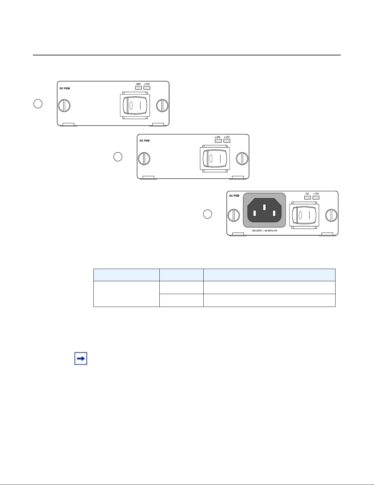
2.4.4 Power Modules
7210 SAS-M 24F 2XFP ETR variant provides three power module options: –48V,
+24V and universal AC. See Figure 5 for an illustration of the power modules.
For specifications on the power modules and external input power requirements, see
section 3.2.4 and section 7.
closure from pin 8)
22
3HE 10089 AAAA TQZZA Edition 01 Issue: 07
Page 23
7210 SAS-M CHASSIS INSTALLATION GUIDE System Overview
1
3
2
+24V ETR
-48V
Figure 5 AC and DC Power Modules
Table 4 Power Module LEDs
LED Condition Status
AC, –48V,+24,
Green DC or AC power is functioning normally
+12V
Off External power not connected or has failed
The –48V/+24V/AC LEDs on the left indicate the status of external power. The +12V
LED on the right indicates the status of the internal power conversion process.
Note:
• You must use AC and/or DC power modules with your 7210 SAS-M. AC and DC power
module can be used simultaneously.
• The 7210 SAS-M 24F 2XFP ETR variant must use a power module which supports
extended temperature range.
• The +24V DC power module must not be used simultaneously with the –48V DC power
module.
• The +24V DC ETR power module is supported on the all 7210 SAS-M variants
(including non-ETR).
Issue: 07 3HE 10089 AAAA TQZZA Edition 01 23
Page 24
System Overview
2.4.4.1 DC power source failure detection
7210 SAS-M CHASSIS INSTALLATION GUIDE
The 7210 SAS-M platform provides capability to detect DC power source (–48V or
+24V source) failure. The 7210 SAS-M chassis allows two DC power sources to be
connected to the chassis. If the system detects that the DC power source has failed,
it raises a critical alarm (the Critical LED is lit and the Critical Alarm output pin is
triggered) and the system's status LED turns amber and blinks. The alarm is cleared
if the DC power source is restored. No user configuration is required to enable this
feature. The software enables this feature automatically by detecting the capability
of the hardware platform.
The system has two slots for AC or DC power supplies. It associates the DC power
supply in the top slot with power source feed A (–48V or +24V Ret-A on the chassis)
and the DC power supply in the bottom slot with power source feed B (–48V or
+24VRetB on the chassis). The system detects the failure of power source feed A
only if the DC power supply is plugged into the top slot. Similarly, the system detects
the failure of power source feed B only if the DC power supply is plugged into the
bottom slot. The trap message generated by the system indica tes that there was an
input failure for the power supply associated with the power input feed that failed.
Note:
• New traps must be explicitly enabled by the user and are suppressed by default.
• The power feeds are summed up internally before feeding the power supply units.
Therefore, the DC power supply units will output power even if only one of the power
source feeds are available.
• Please refer to the release notes to determine which software release supports this
feature.
Table 5 lists the conditions under which the system detects a power source failure.
Table 5 Power Source Failure Detection Capability
Power Feed A
(Available/
Failed)
Power Feed B
(Available/
Failed)
Power
Supply in
Top Slot
(PS1)
Power
Supply in
Bottom
Slot
(PS2)
Alarm
Generated
(Yes/No)
Notes
Available Available DC DC No —
Available Failed DC DC Yes PS2 input failure / PS2 output
OK
Failed Available DC DC Yes PS1 input failure / PS1 output
OK
24
3HE 10089 AAAA TQZZA Edition 01 Issue: 07
Page 25

7210 SAS-M CHASSIS INSTALLATION GUIDE System Overview
Table 5 Power Source Failure Detection Capability (Continued)
Power Feed A
(Available/
Failed)
Power Feed B
(Available/
Failed)
Power
Supply in
Top Slot
(PS1)
Power
Supply in
Bottom
Slot
(PS2)
Alarm
Generated
(Yes/No)
Notes
Failed Failed DC DC — No power to system
Available Available None DC No —
Available Failed None DC Yes PS2 input failure / PS2 output
OK
Failed Available None DC No Input failure / Not detected
Failed Failed None DC — No power to system
Available Available DC None No —
Available Failed DC None No Input failure / Not detected
Failed Available DC None Yes PS1 input failure / PS1 output
OK
Failed Failed DC None — No power to system
Available Available AC DC No —
Available Failed AC DC Yes PS2 input failure / PS2 output
OK
Failed Available AC DC No Input failure / Not detected
Failed Failed AC DC Yes PS2 input failure / PS2 output
failure
Available Available DC AC No —
Available Failed DC AC No Input failure / Not detected
Failed Available DC AC Yes PS1 input failure / PS1 output
OK
Failed Failed DC AC Yes PS1 input failure / PS1 output
OK
Issue: 07 3HE 10089 AAAA TQZZA Edition 01 25
Page 26
System Overview
2.4.5 USB Port
The USB port is reserved for future use.
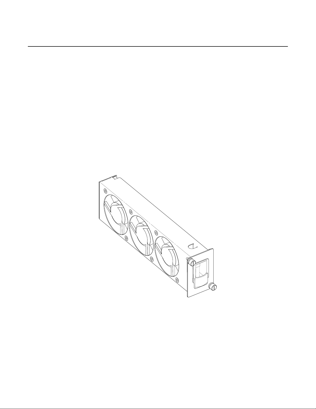
2.4.6 Fan Tray
A hot-swappable fan tray on the right side of the front panel contains three fans that
provide cooling for the chassis. See Figure 6 for an illustration of the fan tray.
The fans are controlled by the system software, and their speed is set according to
the environmental temperature surrounding the switch. Allow at least 3 in. (7.62 cm)
of clearance on the side of the rack to ensure proper airflow intake cooling system.
The fan trays must be in place before the chassis is powered on.
Figure 6 Fan Tray
7210 SAS-M CHASSIS INSTALLATION GUIDE
26
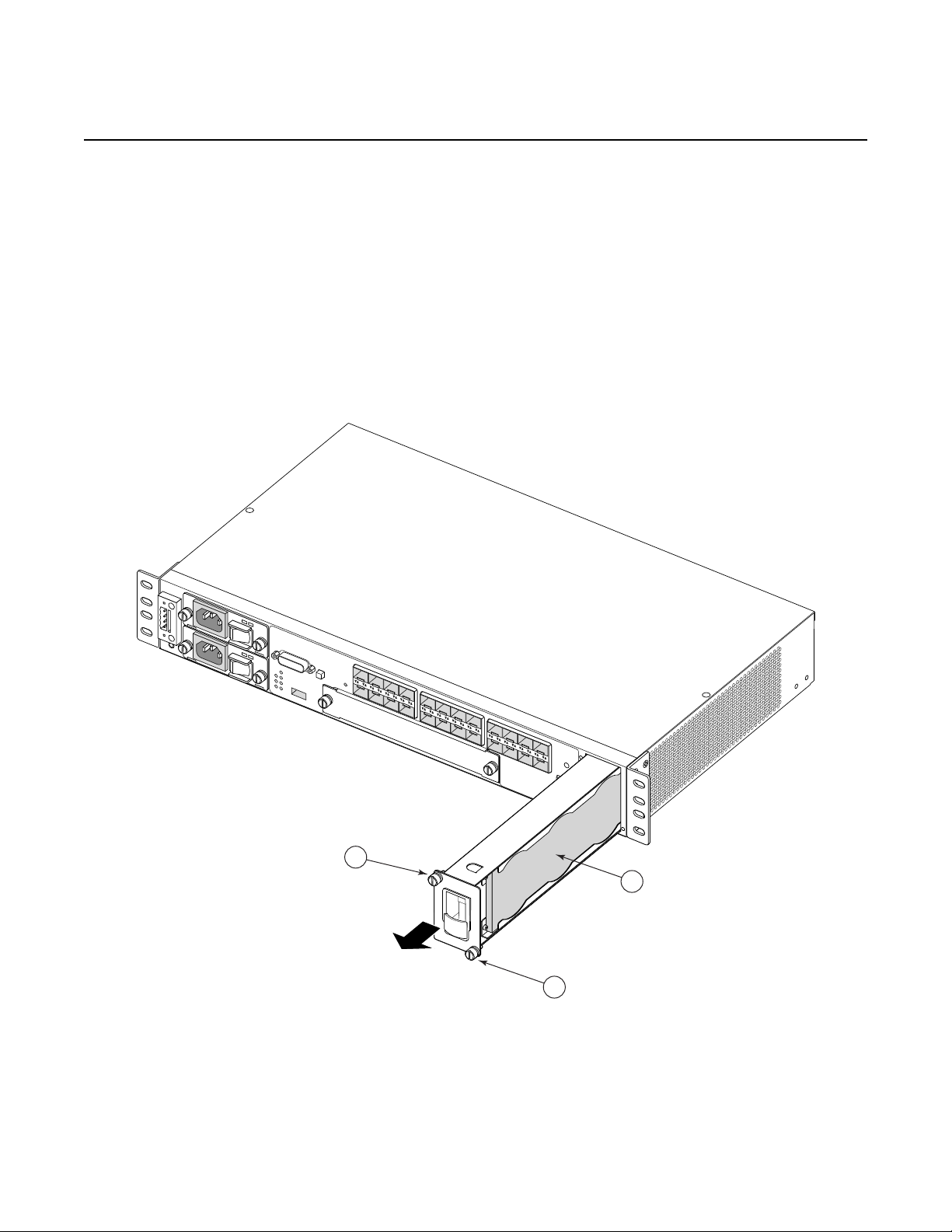
The fan tray also contains an air filter. The filter tray must always be installed while
the chassis is powered up. The air filter prevents large particles, debris, and dust
from entering and circulating through the system. Inspect your air filter month ly and
replace it when accumulated dust is present.
3HE 10089 AAAA TQZZA Edition 01 Issue: 07
Page 27
7210 SAS-M CHASSIS INSTALLATION GUIDE System Overview
SR72027
1
1
2
To inspect and remove your air filter, see Figure 7 and perform the following steps:
Step 1. Loosen the captive screws on the fan tray (Figure 7 item 1).
Step 2. Carefully remove the fan tray from the router chassis and remove the air
filter (Figure 7 item 2) to inspect it and replace it (3HE06340AA), if
necessary.
Step 3. After inspecting and replacing the air filter, replace it in the fan tray so that
the edge of the air filter is flush with the rear of the fan tray.
Step 4. Replace the fan tray and tighten the captive screws.
Figure 7 Removing and Replacing the Fan Tray and Air Filter
Issue: 07 3HE 10089 AAAA TQZZA Edition 01 27
Page 28
System Overview
Crit
32 54
1 6
SR72025
2.4.7 System LEDs and Buttons
The LEDs are located on the front panel and the power module trays. See Figure 8
for the location of the system LEDs and buttons, Table 6 for key descriptions, and
Table 7 for alarm descriptions.
Figure 8 System LEDs and Buttons
7210 SAS-M CHASSIS INSTALLATION GUIDE
Table 6 7210 SAS-M System LEDs and Buttons
Key Description
1 Alarm LEDs and 10G port LEDs for 7210 SAS-M 24F
2XFP and 7210 SAS-M 24F 2XFP ETR only
2 Alarm Cut Off button
3 Reset button
4 100/1000 SFP port LEDs
5 Management port
6 Console port
28
3HE 10089 AAAA TQZZA Edition 01 Issue: 07
Page 29

7210 SAS-M CHASSIS INSTALLATION GUIDE System Overview
2.4.8 System and Port LEDs
Table 7 System and Port Status LEDs
LED Condition Status
Critical Red Indicates that a critical condition exists
Major Amber Indicates that a serious condition exists
Fan Off Indicates that the fans are functioning properly
Red Indicates that one or more fans have failed, or that
the fan tray is not connected
Note: The LED blinks red during the boot process
Status Green Indicates that the system has completed the boot
phase and is running normally
Amber (blinking) Indicates that a power supply has failed
2.4.9 Port LEDs
The port LEDs are described in Table 8.
Table 8 Port LEDs
LED Condition Status
SFP ports 1–24 Green Indicates that the port has a valid
XFP ports 25, 26 Green Indicates that the port has a valid
See Figure 9 for an illustration of two sample ports and the corresponding LEDs.
Table 9 provides the key descriptions.
link
Green (blinking) Indicates activity on the port
Off Indicates that the link is down
link
Green (blinking) Indicates activity on the port
Off Indicates that the link is down
Issue: 07 3HE 10089 AAAA TQZZA Edition 01 29
Page 30

System Overview
1
2
3
4
5
5
SR72007
7210 SAS-M CHASSIS INSTALLATION GUIDE
Figure 9 SFP Port LEDs
Table 9 Port LED Key Descriptions
Key Description
1Reserved
2 LED that indicates status for an odd-numbered port. Odd-numbered ports
are in the top row.
3Reserved
4 LED that indicates status for an even numbered port. Even-numbered
ports are in the bottom row.
5SFP slots
30
3HE 10089 AAAA TQZZA Edition 01 Issue: 07
Page 31

7210 SAS-M CHASSIS INSTALLATION GUIDE System Overview
2.4.10 System Buttons and Switches
See Table 10 for descriptions of front panel buttons and switches.
Table 10 Front Panel Buttons and Switches
Button/Switch Condition Status
Power module
switch
ACO (Alarm Cut
Off)
Reset (recessed) Not
0 Standby mode if switch is connected to a power
1 AC or DC power is applied to the switch
Not
pushed
pushed
source
Normal operating mode
Normal operating mode. To reset hardware,
follow reset procedure mentioned in section 5.4.
Issue: 07 3HE 10089 AAAA TQZZA Edition 01 31
Page 32

7210 SAS-M CHASSIS INSTALLATION GUIDE Installing the Chassis
3 Installing the Chassis
This chapter provides information on installing a 7210 SAS-M chassis and includes
the following sections:
• Site Preparation, section 3.1
• Installing Your Switch, section 3.2
Issue: 07 3HE 10089 AAAA TQZZA Edition 01 33
Page 33

Installing the Chassis
3.1 Site Preparation
3.1.1 Selecting a Site
7210 SAS-M CHASSIS INSTALLATION GUIDE
Mount the 7210 SAS-M in a standard 19-inch equipment rack or on a flat surface.
When you mount your switch on a flat surface, ensure that the four rubber feet are
installed on the bottom of the chassis.
The site should be a weather-protected and temperature-controlled location, and
should include the following criteria:
• The 7210 SAS-M supports temperature operation from 32 to 122ºF (0 to
50ºC). The 7210 SAS-M 24F 2XFP ETR variant supports extended
temperature operation from –40 to 149ºF (–40 to 65ºC). Humidity levels in the
site must be controlled to ensure a relative humidity level between 5 and 95%
(non-condensing) for both the 7210 SAS-M and 7210 SAS-M 24F 2XPF ETR.
• Provide adequate space on the front and two sides of the unit to enable
servicing and proper air flow.
• Ensure that the installation site is secure and only authorized service
personnel are allowed to access the unit (IEC 60950 safety requirement).
For more information about installation site assessment, see section 10.
3.1.2 Ethernet Cabling
To ensure proper operation in a network, make sure that the cables are suitable fo r
100/1000 fiber-optic or 10/100/1000 Base-T copper operation. Make sure your
installation complies with the following guidelines:
• Cable type: shielded twisted pair (STP) cables with RJ-45 connectors;
Category 3 or better for 10 Base-T, Category 5 or better for 100 Base-Tx, and
Category 5, 5e or 6 for 1000 Base-T.
• Make sure cables are not damaged and RJ-45 connectors are seated.
• Avoid installing copper cables close to strong electromagnetic fields
generated by electric generators, elevator motors, or similar heavy electric
machines.
• Make sure you only use SFPs and XFPs that are supported by Nokia.
34
3HE 10089 AAAA TQZZA Edition 01 Issue: 07
Page 34

7210 SAS-M CHASSIS INSTALLATION GUIDE Installing the Chassis
SR72009
3.2 Installing Your Switch
3.2.1 Rack Mounting
Before you begin, verify that:
• the equipment rack is securely installed, anchored, and grounded. Refer to
the rack manufacturer’s documentation for instructions.
• nearby equipment, including breaker panel bus bars and power connectors,
is made safe. Either shut off the power, if possible, or install safety guards or
mats over exposed power points and cables.
Required tools:
• Bracket Mounting Kit for each device you plan to install in a rack
• Four rack-mounting screws (not included) for each device you plan to install
in a rack
• A screwdriver appropriate for the rack-mount screws
To install the 7210 SAS-M in a rack:
Step 1. Attach the brackets to the device using the screws provided in the Bracket
Mounting Kit, as shown in Figure 10.
Figure 10 Attaching the Brackets
Issue: 07 3HE 10089 AAAA TQZZA Edition 01 35
Page 35

Installing the Chassis
SR72010
7210 SAS-M CHASSIS INSTALLATION GUIDE
Step 2. Mount the 7210 SAS-M in the rack using four rack-mounting screws, as
shown in Figure 11.
Figure 11 Installing the Switch in a Rack
Step 3. If you are installing a single switch, proceed to Grounding the Chassis on
page 38.
Step 4. If installing multiple switches, mount them in the rack, one below the other,
in any order.
36
3HE 10089 AAAA TQZZA Edition 01 Issue: 07
Page 36

7210 SAS-M CHASSIS INSTALLATION GUIDE Installing the Chassis
SR72026
3.2.2 Desktop or Shelf Mounting
Before starting this procedure, ensure you have the following:
• four adhesive feet (provided with the 7210 SAS-M)
• an available grounding point near the installation location
Step 1. Attach the four adhesive feet to the bottom of the first switch, as shown in
Figure 12.
Figure 12 Attaching the Adhesive Feet
Step 2. Set the device on a flat surface near an external power source, making sure
there are at least three inches of space on the front and sides for proper air
flow.
Step 3. If you are installing a single switch, proceed to "Grounding the Chassis" on
page 38.
Step 4. If you are installing multiple switches, attach four adhesive feet to each
switch. Place each device squarely on top of the one below, in any order.
Issue: 07 3HE 10089 AAAA TQZZA Edition 01 37
Page 37

Installing the Chassis
3.2.3 Grounding the Chassis
7210 SAS-M CHASSIS INSTALLATION GUIDE
The router is suitable for installation as part of the Common Bonding Network (CBN)
or an Isolated Bonding Network (IBN). The router is suitable for installation in
Network Telecommunication Facilities or locations where the NEC applies.
Required tools and hardware:
• wire stripper
• wire cutter
• screwdriver appropriate for M4-.7 pitch screws
• #8 AWG stranded copper wire (green, or green/yellow)
Before powering on the switch, ground the switch to earth as described below.
Step 1. If mounting the switch in a rack, ensure that the rack on which the switch is
to be mounted is properly grounded.
Step 2. Ensure that you have made a suitable electrical connection to the grounding
point on the rack. Ensure that no paint or isolating surface treatment is
present on the grounding point.
Step 3. Disconnect all power cables to the switch.
Step 4. Locate the grounding terminal. The switch chassis is connected internally to
0 V. This circuit is connected to the double-hole grounding terminal on the
rear of the switch (lower right corner) using Metric M4-.7 pitch screws and a
Panduit LCCF8-14A-L or compatible ground lug. The surface area around
this terminal is not painted in order to provide for a good connection.
Step 5. Using a wire-stripping tool, strip the insulation from the end of the #8 AWG
stranded copper wire according to local safety codes. Attach the wire to the
grounding terminal on the switch.
Step 6. Using a wire-stripping tool, strip the insulation from the free end of the #10
AWG stranded copper wire according to local safety codes. Attach the wire
to the ground point on the rack.
Danger: The earth connection must not be removed unless all supply connections have
been disconnected.
38
3HE 10089 AAAA TQZZA Edition 01 Issue: 07
Page 38

7210 SAS-M CHASSIS INSTALLATION GUIDE Installing the Chassis
Warning:
• HIGH LEAKAGE CURRENT: EARTH CONNECTION ESSENTIAL BEFORE
CONNECTING SUPPLY.
COURANT DE FUITE ÉLÉVE: Raccordement à la terre indispensable avant le
raccordement au réseau.
• Chassis ground cables are not included. Use only power cords that have a grounding
(earthing) path. Use only power cords that have a grounding (earthing) path. Main
grounding (earthing) connection points are through the IEC60320 appliance inlets.
Grounding (earthing) points on the rear of the equipment are for equipotential bon ding
only and are not the safety grounding (earthing) points for the equipment. Lack of prop er
grounding (earthing) of the equipment may result in a safety hazard and excessive
electromagnetic emissions. See Table 11 on page 47 for descriptions of common
grounding-type (earthing) power supply cords.
If you ground the equipment by a method other than those provided in this manual,
those means should be in compliance with all local wiring regulations and practices
• To comply with the GR-1089-CORE, Issue 03, requirement R4-9 [31] standard for
electromagnetic compatibility and safety, all intra-building ports are specified for use
with shielded and grounded cables at both ends.
The intra-building port(s) of the equipment or sub-assembly is suitable for connection to
intrabuilding or unexposed wiring or cabling only. The intra-building port(s) of the
equipment or sub-assembly must not be metallically connected to interfaces that
connect to the Outside Plant (OSP) or its wiring. These interfaces are designed for use
as intra-building interfaces only (Type 2 or Type 4 ports as described in GR-1089CORE, Issue 4) and require isolation from the exposed OSP cabling. The addition of
primary protectors is not sufficient protection in order to connect these interfaces
metallically to OSP wiring.
• Bare conductors must be coated with an appropriate antioxidant compound before
crimp connections are made. All unplated connectors, braided strap, and bus bars must
be brought to a bright finish and then coated with an antioxidant befor e they are
connected.
• The equipment under test (EUT) is specified for DC-I power configurations. The battery
returns must remain isolated until they reach the main power bus.
• Only electrical service personnel should perform wiring and cabling to the system.
• All power to the equipment rack or cabinet should be disconnected before the
installation.
• Power cable(s) must meet your local electric code requirements.
• The power supply on/standby switch is not intended to be used as the chassis ON/OFF
switch. Unplug the power cord from the power source and disconnect the cor d from the
receptacle on the power supply module to remove power.
• An external circuit br ea ke r no grea te r tha n 15 A must be loca te d with in a re ad ily
accessible distance of the equipment. This is intended as the disconnect device.
Issue: 07 3HE 10089 AAAA TQZZA Edition 01 39
Page 39

Installing the Chassis
3.2.4 Connecting to a Power Source
3.2.4.1 Connecting to AC Power
7210 SAS-M CHASSIS INSTALLATION GUIDE
This switch supports both AC and DC power supply modules.
Caution: The 7210 SAS-M 24F 2XFP ETR version must use the extended temperature
range power module.
Note: The switch is designed to accept up to two AC or two DC power modules. The switch
also accepts a single AC and single DC power module.
Note: In order to comply with the GR-1089 Lightning Criteria for Equipment Interfacing With
AC Power Ports, an external Surge Protective Device (Perma Power Model # PXD309) is
intended to be used at the AC input of the switch.
To connect the 7210 SAS-M to a power source:
Step 1. Verify that the external AC power source has the following rating: 100-
240VAC, 50/60 Hz, 2A.
Step 2. Install the AC power module. Make sure the AC power module is powered
OFF before you plug the power cable in to the AC power source.
Step 3. Plug the power cable in to the AC power source.
Step 4. Power on the AC power module. Check the power module LEDs as the
7210 SAS-M is powered on to verify that the AC LED indicating external
power status is on, and that the +12V LED indicating internal power
conversion is on. If not, recheck the power supply and power cable
connections at the supply source and at the power module.
Note: A redundant AC power module may be hot swapped in. However, for safety
precautions the main power cord should be connected after the AC power module is
installed.
40
Step 5. If you have installed both primary and redundan t power modules, verify that
the LEDs on both modules are lit as indicated in step 4.
3HE 10089 AAAA TQZZA Edition 01 Issue: 07
Page 40

7210 SAS-M CHASSIS INSTALLATION GUIDE Installing the Chassis
3.2.4.2 Connecting to DC Power
The 7210 SAS-M chassis supports the –48V and +24V DC power modules. Hence,
the steps below are applicable for either the –48V or the +24V DC power modules.
Danger: Before wiring the DC plug or connecting power to the switch, en sure that power to
the feed lines is turned off at the supply circuit breaker or disconnected from the power bus.
Caution: Do not install a –48V and a +24V AC power module in a 7210 SAS- M chassis the
same time.
Note:
• An additional chassis ground point is located below the DC power entry block, for
attaching a DC power chassis ground if required by local electrical codes. The ground
point should be connected with an M4 screw and a terminal lug as specified by local
electrical codes.
• If a single power feed (either A or B) is connected to provide power to the system, it
supplies power to both of the power modules if two modules are plugged in. The DC
power feeds, A and B, are internally bridged using a diode.
• To provide adequate circuit protection between the DC power supply and the switch, all
intermediate wiring and circuitry should be rated to carry a load at least two times the
maximum rating for the 7210 SAS-M (see Specifications on page 73).
• The wiring between the DC power supply and the 7210 SAS-M must be stranded
copper wire within the range of 16 to 20 AWG in accordance with local electrical codes.
Required tools: a small flat-tip screwdriver
To connect DC power:
Step 1. Before a VDC power module can be used, you must connect an external DC
power source to the DC power connection on the left side of the front panel
(see Figure 1). The external DC power supply must be between –36 to –72
VDC, and protected with a circuit breaker.
Step 2. Connect the VDC power feed using the VDC input and RET A/B (return)
lines for power source A and B, respectively. Insert the wires in to the DC
input plug using a small flat-tip screwdriver. Color code the wiring according
to local standards to ensure that the input power and ground lines can be
easily distinguished.
Issue: 07 3HE 10089 AAAA TQZZA Edition 01 41
Page 41

Installing the Chassis
-48V (A) (Pin 1)
Return (A) (Pin 2)
-48V (B) (Pin 3)
Return (B) (Pin 4)
DC PEM
200W
DC PEM
200W
7210 SAS-M CHASSIS INSTALLATION GUIDE
Warning:
If the power leads are plugged in to the wrong holes, the power module will not work properly
and may damage the 7210 SAS-M.
Figure 13 illustrates how to connect a –48 VDC power source to the
chassis:
Figure 13 Connecting to a –48 VDC Power Source
42
Figure 14 illustrates how to connect a +24 VDC power source to the
chassis:
3HE 10089 AAAA TQZZA Edition 01 Issue: 07
Page 42

7210 SAS-M CHASSIS INSTALLATION GUIDE Installing the Chassis
Ground (A) (Pin 1)
+24V (A) (Pin 2)
Ground (B) (Pin 1)
+24V (B) (Pin 2)
+24V
DC PEM
200W
+24V
DC PEM
200W
Figure 14 Connecting to a +24 VDC Power Source
Step 3. After the power source is turned on, switch the power button on the front of
the power module to the ON position (marked “—”).
Step 4. Check the LEDs on the power module as the switch is powered on to verify
that the –48V/+24V LED indicating external power status is on, and that the
+12V LED indicating internal power conversion is on. If not, recheck the
power cable connections at the power source and the power module.
Step 5. If you have installed both a primary and redundant power module, verify that
the LEDs on both modules are lit as indicated in step 4.
Issue: 07 3HE 10089 AAAA TQZZA Edition 01 43
Page 43

Installing the Chassis
3.2.4.3 Connecting to the Console Port
7210 SAS-M CHASSIS INSTALLATION GUIDE
The RJ-45 serial port on the front panel is used to connect to the switch for out-ofband console configuration. The on-board configuration program can be accessed
from a terminal or a PC running a terminal emulation program.
The pin assignments used to connect to the Console port are provided in Table 11.
Table 11 Serial Port Pin Assignment
Signal Pin Usage
RTS 1 Request to send
NC 2 Not connected
TXD 3 Transmit data
GND 4 Signal ground
GND 5 Signal ground
RXD 6 Receive data
NC 7 Not connected
CTS 8 Clear to send
44
3HE 10089 AAAA TQZZA Edition 01 Issue: 07
Page 44

7210 SAS-M CHASSIS INSTALLATION GUIDE Transceivers
4 Transceivers
This chapter describes how to replace small form-factor pluggable (SFP)
transceivers on MDA ports that support these devices.
• Warnings and Notes, section 4.1
• Installation Preparation, section 4.2
• Locking and Release Mechanisms, section 4.2.1
• Installing SFP/XFPs, section 4.2.2
• Removing and Replacing SFP/XFPs, section 4.2.3
Issue: 07 3HE 10089 AAAA TQZZA Edition 01 45
Page 45

Transceivers
7210 SAS-M CHASSIS INSTALLATION GUIDE
4.1 Warnings and Notes
Danger:
• Fiber-optic equipment can emit laser or infrared light that can injure your eyes. Never
look into an optical fiber or connector port. Always assume that fiber-optic cables are
connected to a light source.
Caution:
• Make sure the plug is inserted while you install or remove the SFP. Only remove the
plug when you are ready to attach network cables.
• Electrostatic discharge (ESD) damage can occur if switch components, including SFPs,
are mishandled. Always wear an ESD-preventive wrist or ankle strap and always
connect an ESD strap to the grounding plug on the front of the chassis.
• Always place switch components on an anti-static surface.
• Avoid bending fiber-optic cable beyond its minimum bend radius.
• Do not exceed the recommended minimum 1.5 in. (3.81 cm) bend radius for fiber-optic
cables.
Note:
• Do not remove the dust cover on the connector until you are ready to install the SFP.
Always replace the dust cover when the SFP is removed.
• Discard SFPs according to all local laws and regulations.
• SFPs are keyed to prevent incorrect insertion.
46
3HE 10089 AAAA TQZZA Edition 01 Issue: 07
Page 46

7210 SAS-M CHASSIS INSTALLATION GUIDE Transceivers
4.2 Installation Preparation
Clean the connector on the fiber cable before inserting it in to the SFP/XFP to prevent
transferring small particles and contaminating the transceiver. Do not interchange
SFP/XFPs from one port to another without first cleaning the connectors.
To clean the connector, you can either:
• Wipe the side and end of the ferrule with a lint-free alcohol-dampened cloth.
• Blow dry the ferrule with compressed air and inspect for lint. Do not insert the
compressed air nozzle into the receptacle when blowing out.
4.2.1 Locking and Release Mechanisms
Nokia SFP/XFPs can use different lock and release methods. Possible lock and
release mechanisms include:
• Locking handle—A locking handle (lever) in the front of the SFP/XFP that you
gently raise or lower to insert or remove the module from the port.
• Bail — A bar or wire latch in the front of the SFP/XFP that you pull down and
outward to release the module.
• Tabs on the sides of the SFP/XFP that you press inward to release the
module.
4.2.2 Installing SFP/XFPs
To install an SFP/XFP transceiver:
Step 1. Remove the SFP/XFP from its anti-static packaging.
Step 2. Holding the SFP/XFP by its sides, slide the unit into the port until it clicks
into place.
Step 3. Remove the plug from the SFP/XFP optical bore when you are ready to
attach the network cable.
Issue: 07 3HE 10089 AAAA TQZZA Edition 01 47
Page 47

Transceivers
7210 SAS-M CHASSIS INSTALLATION GUIDE
4.2.3 Removing and Replacing SFP/XFPs
When you are replacing an SFP/XFP, have the following parts ready:
• a replacement SFP/XFP
• protective plugs for the SFP/XFP and a dust cover for the fiber cable
connector
• an anti-static mat or electrostatic bag
To remove an SFP/XFP:
Step 1. Disconnect the cable from the SFP/XFP connector.
Step 2. Place a protective plug in the SFP/XFP that is being removed.
Step 3. Release the locking mechanism on the SFP/XFP with your thumb and
forefinger. See section 4.2.1 for descriptions of the different SFP/XFP lock
and release methods. Slide the SFP/XFP out of the port.
Step 4. Place the SFP/XFP on an anti-static mat or in an electrostatic bag.
Step 5. Install a replacement SFP/XFP into the port.
Step 6. Connect the fiber cable, or if you are not immediately connecting a fiber
cable, insert a protective plug into the SFP optical port and place a dust
cover on the fiber cable connector.
Note: Ensure that the temperature ratings for the SFPs and XFPs match those of the
intended operating environment.
48
3HE 10089 AAAA TQZZA Edition 01 Issue: 07
Page 48

7210 SAS-M CHASSIS INSTALLATION GUIDE Configuring the System
5 Configuring the System
This chapter describes how to configure your 7210 SAS-M and contains the following
sections:
• Diagnostics, section 5.1
• Initializing the System and Downloading Software, section 5.2
• Establishing Router Connections, section 5.3
• Restarting the Router, section 5.4
Issue: 07 3HE 10089 AAAA TQZZA Edition 01 49
Page 49

Configuring the System
5.1 Diagnostics
5.1.1 Post Installation Status
After successfully installing and powering up the 7210 SAS-M, en sure that the LEDs
show the following state:
If any of the above LEDs show a different state, reset the hardware using the reset
procedure mentioned in section 5.4 to let the system boot.
7210 SAS-M CHASSIS INSTALLATION GUIDE
• Critical: OFF
• Major: OFF
• Fan: OFF
• Status: Steady GREEN
50
3HE 10089 AAAA TQZZA Edition 01 Issue: 07
Page 50

7210 SAS-M CHASSIS INSTALLATION GUIDE Configuring the System
OSSG325
FTP
Server
IP Address:
10.10.170.22/24
Port: 24
IP Address: 10.135.4.172/24
Gateway: 10.135.4.1
Console Cable
SAS-M
5.2 Initializing the System and Downloading Software
The 7210 SAS-M ships with bootloader and TiMOS on the compact flash memory
device. When the system is powered up for the first time, the bootloader will attempt
an auto-init procedure (see the System Basics Guide for more information).
However, the auto-init can be interrupted and the boot operation controlled manually.
Note: By default, 7210 SAS platforms attempt the autoinit procedure unless interrupted by
user and forced to use TiMOS available in the flash.
5.2.1 Booting in the Lab
There are several ways to boot the 7210 SAS-M from the network. You can choose
to boot the device using one of the following options:
• Using the image shipped along with the 7210 SAS-M to boot the device
• Using the network to load the image and boot the device
The following sections describe how to boot the device using either of the options
listed above.
Figure 15 7210 SAS-M Boot Process
Issue: 07 3HE 10089 AAAA TQZZA Edition 01 51
Page 51

Configuring the System
5.2.1.1 Booting Using the Image on Flash
You will need the following:
Connect the 7210 SAS-M console port to serial port of the PC and then power up the
7210 SAS-M. The system will start booting up with messages on the console similar
to those shown below. Follow the prompts given below to boot the system with the
image on the flash.
Resetting...OK
Nokia 7210 Boot ROM. Copyright 2009-2011 Nokia.
All rights reserved. All use is subject to applicable license agreements.
Testing ROM load area...done
Relocating code...Jumping to RAM
Performing second stage RAM test....passed
Board Serial Number is 'NS1111C0115'
Bootlog started for Version A-V-3.0.B5-85
Build V-3.0.B5-85 bootrom/mpc 7xxx
Built on Wed Apr 20 13:52:05 IST 2011 by builder in /builder/3.0B5/panos/main
?Attempting to load from file cf1:/boot.tim
Version L-3.0.B5-85, Wed Apr 20 14:13:38 IST 2011 by builder in /builder/3.0B5/panos/
main
text:(4782384-->20108848) + data:(1084015-->3891872)
Starting at 0xb000000...
PCIe: Port 0 Link UP
Total Memory: 512MB Chassis Type: sas Card Type: badami_7210
TiMOS-L-3.0.B5-85 boot/mpc NOKIA SAS-M 6F4T 7210 Copyright (c) 2000-2011 Nokia.
All rights reserved. All use subject to applicable license agreements.
Built on Wed Apr 20 14:13:38 IST 2011 by builder in /builder/3.0B5/panos/main
TiMOS BOOT LOADER
Time from clock is THU APR 21 11:03:21 2011 UTC
Switching serial output to sync mode... done
7210 SAS-M CHASSIS INSTALLATION GUIDE
• A PC with a serial port and hyperterminal
• An RJ-45 serial cable that connects the console port of the 7210 SAS-M to
the serial port of a PC
52
Since the switch does not ship with a BOF, it will show the default settings.
Looking for cf1:/bof.cfg ... not found
Could not find bof.cfg on any of the local drives.
Default Settings:
---------------------------------------------------------------------------
---------------------Contents of Boot Options File on cf1:
#uplinkA Port Settings:
uplinkA-port 1/1/1
uplinkA-address 0
uplinkA-vlan 0
#uplinkB Port Settings:
uplinkB-port 1/1/2
uplinkB-address 0
uplinkB-vlan 0
#System Settings:
3HE 10089 AAAA TQZZA Edition 01 Issue: 07
Page 52

7210 SAS-M CHASSIS INSTALLATION GUIDE Configuring the System
wait 3
persist off
console-speed 115200
Hit a key within 2 seconds to change boot parameters...
Press any key.
Enter password to edit the Boot Options File
Or CTRL-D to exit the prompt
Password:
The default password is password.
You must supply some required Boot Options. At any prompt, you can type:
"restart" - restart the query mode.
"reboot" - reboot.
"exit" - boot with with existing values.
"diag" - enter the diag shell.
"reset" - reset the bof and reboot.
Press ENTER to begin, or 'flash' to enter firmware update...
Press <Enter>.
Software Location
----------------You must enter the URL of the TiMOS software.
The location can be on a Compact Flash device,
or on the network.
Here are some examples
cf1:/timos1.0R1
ftp://user:passwd@192.168.1.150/./timos1.0R1
tftp://192.168.1.150/./timos1.0R1
Software Image URL:
Enter the software URL. (For example, cf1:/both.tim)
At the prompt above, enter the location of the image. When the device ships from the
factory the image is typically available at cf1:/both.tim
Configuration File Location
--------------------------You must enter the location of configuration
file to be used by TiMOS. The file can be on
a Compact Flash device, or on the network.
Here are some examples
cf1:/config.cfg
ftp://user:passwd@192.168.1.150/./config.cfg
tftp://192.168.1.150/./config.cfg
No existing Config URL
Press ENTER, or type 'none' for no Config URL.
Config File URL:
Enter the location of the configuration file. Or none since you are booting for the first
time. You can skip all the remaining prompt that appear on the screen by pressing
<Enter> until you get to the following prompt
Issue: 07 3HE 10089 AAAA TQZZA Edition 01 53
Page 53

Configuring the System
New Settings
-----------primary-image cf1\both.tim
primary-config cf1:\config.txt
#uplinkA Port Settings:
uplinkA-port 1/1/10
uplinkA-address 10.135.4.172/10
uplinkA-vlan 0
uplinkA-route 10.10.170.0/10 next-hop 10.135.4.1
#System Settings:
wait 3
persist off
console-speed 115200
Do you want to overwrite cf1:/bof.cfg with the new settings? (yes/no):
Type yes and press Enter. The 7210 SAS-M should boot now.
Primary image location: cf1:/both.tim
Loading image cf1:/both.tim
Version B-3.0.B5-85, Wed Apr 20 14:32:04 IST 2011 by builder in /builder/
3.0B5/panos/main
text:(25059814-->122242456) + data:(3179598-->18748616)
Executing TiMOS image at 0x100000
After the 7210 SAS-M boots up, you should see the following prompt:
7210 SAS-M CHASSIS INSTALLATION GUIDE
All rights reserved. All use subject to applicable license agreements.
Built on Wed Apr 20 14:32:04 IST 2011 by builder in /builder/3.0B5/panos/
main
Login:
Note: The SYS LED will be green when the device has successfully completed the boot
process and is running normally.
Both the default username and password are admin. Log in to the 7210 SAS-M. To
establish either console connection or Telnet connection to the 7210 SAS-M after a
successful boot, please see "Establishing Router Connections" on page 65.
5.2.1.2 Booting From the Network
There are several ways to boot the 7210 SAS-M from the network. User has options
to use one of the front panel ports (refered to as uplinkA and uplinkB in the display
output shown below) or the out-of-band ethernet management port (refered to as ethmgmt port in the display output shown below) to boot the 7210 SAS-M from the
network. By default, the out-of-band ethernet management port is disabled. User
needs to enable it before using it for manual boot. The example below shows how
this can be done. The example described below shows how to boot the 7210 SASM using FTP servers and the manual boot process. For more information about
54
3HE 10089 AAAA TQZZA Edition 01 Issue: 07
Page 54

7210 SAS-M CHASSIS INSTALLATION GUIDE Configuring the System
booting your 7210 SAS-M, please refer to the System Basics Guide. Figure 15
shows the network diagram used in the example below. Additionally, you may want
to store the TiMOS image on the internal flash if you want to b oot from the flash later.
You will need the following:
• An FTP server
• The TiMOS software image
• A PC with a serial port and Hyperterminal
• An RJ-45 serial cable that connects the console port of the 7210 SAS-M to
the serial port of PC
• A network cable to connect the 7210 SAS-M to the network
Prepare the setup as shown in the diagram above. Ensure that the console settings
are set as shown in Console Connection on page 65.
When you are done, power on the 7210 SAS-M.
Using the uplink port to boot the 7210 SAS-M from the network:
Resetting...OK
ø
Nokia 7210 Boot ROM. Copyright 2000-2009 Nokia.
All rights reserved. All use is subject to applicable license agreements.
Running POST tests from ROM
Testing ROM load area...done
Relocating code...Jumping to RAM
Performing second stage RAM test....passed
Board Serial Number is 'SN12345678'
Bootlog started for Version V-1.0.R1
Build V-1.0.R1 bootrom/mpc 7xxx
Built on Thu Jan 15 14:55:59 IST 2009 by builder in /builder/ws/panos/main
Since the router does not ship with a BOF, it will show the default settings.
Looking for cf1:/bof.cfg ... not found
Could not find bof.cfg on any of the local drives.
Default settings:
------------------------------------------------------------------------------------
------------Contents of Boot Options File on cf1:
#eth-mgmt Port Settings:
eth-mgmt-disabled
#uplinkA Port Settings:
uplinkA-port 1/1/1
Issue: 07 3HE 10089 AAAA TQZZA Edition 01 55
Page 55

Configuring the System
uplinkA-address 0
uplinkA-vlan 0
#uplinkB Port Settings:
uplinkB-port 1/1/2
uplinkB-address 0
uplinkB-vlan 0
#System Settings:
wait 3
persist off
console-speed 115200
Hit a key within 2 seconds to change boot parameters...
Press any key.
Enter password to edit the Boot Options File
Or CTRL-D to exit the prompt
Password:
The default password is password.
You must supply some required Boot Options. At any prompt, you can type:
"restart" - restart the query mode.
"reboot" - reboot.
"exit" - boot with with existing values.
"reset" - reset the bof and reboot.
Press ENTER to begin, or 'flash' to enter firmware update...
7210 SAS-M CHASSIS INSTALLATION GUIDE
Note: The restar t command can be used at any time to start off at the beginning of the me nu
options.
Press <Enter>.
Software Location
---------------- You must enter the URL of the TiMOS software.
The location can be on a Compact Flash device,
or on the network.
Here are some examples
cf1:/timos1.1R1
ftp://user:passwd@192.168.1.150/./timos1.1R1
tftp://192.168.1.150/./timos1.1R1
Software Image URL:
Enter the software URL. (For example, ftp://
<user>:<password>@10.10.170.22/./images/both.tim)
Configuration File Location
-------------------------- You must enter the location of configuration
56
3HE 10089 AAAA TQZZA Edition 01 Issue: 07
Page 56

7210 SAS-M CHASSIS INSTALLATION GUIDE Configuring the System
file to be used by TiMOS. The file can be on
a Compact Flash device, or on the network.
Here are some examples
cf1:/config.cfg
ftp://user:passwd@192.168.1.150/./config.cfg
tftp://192.168.1.150/./config.cfg
No existing Config URL
Press Enter, or type 'none' for no Config URL.
Config File URL:
If you are not booting for the first time, enter the location of the configuration file.
Boot Interface Management
------------------------You specified a network location for either the
software or the configuration file. You need to,
configure either uplinkA or uplinkB ports.
You will be asked to configure the port number, IP address,
static routes, and VLAN Id for uplink ports.
uplinkA Port Setting
-------------------Existing uplinkA port settings are:
uplinkA-port 1/1/1
uplinkA-address 0
uplinkA-vlan 0
uplinkA port is configured for Boot Interface Management,
Press Enter to proceed with existing port settings
Or "disable" to disable the port for Boot Interface Management
Or "edit" to change the port settings:
Type edit.
Existing uplinkA port for Boot Interface Management is port 1/1/1.
Press Enter to keep it.
Enter the new uplinkA port number for Boot Interface Management:
Enter the port that it connected to the network (for example, 1/1/24).
You need to assign an IP address for this port.
The IP address should be entered in standard
dotted decimal form with a network length.
example: 192.168.1.169/24
Or type "0" to obtain IP address and static route
through DHCP. Existing IP address and static routes
will be deleted.
uplinkA port is configured to obtain IP address and static route through dhcp.
Press Enter to keep it.
Enter uplinkA port IP Address:
Enter the IP address and mask that the device should use (for example,
10.135.4.172/24).
Issue: 07 3HE 10089 AAAA TQZZA Edition 01 57
Page 57

Configuring the System
Since the FTP server is on a different subnet, you will have to enter IP routing
information:
You specified network locations which might require
static routes to reach. You will be asked to
enter static routes until all the locations become
reachable.
Static routes should be entered in the following format:
prefix/mask next-hop ip-address
example: 192.168.0.0/16 next-hop 192.168.1.254
Would you like to add a static route? (yes/no)
Type yes and press <Enter>.
Enter route:
Enter a static route to the FTP server's subnet (for example, 10.10.170.0/24
next-hop 10.135.4.1) at the prompt.
You need to configure the VLAN Id for this port
VLAN Id can be between 0 to 4094. To send out
packets with out any VLAN tags, type "null".
7210 SAS-M CHASSIS INSTALLATION GUIDE
Existing VLAN Id for uplinkA port is VLAN Id 0.
Press Enter to keep it.
Enter the new VLAN Id for uplinkA port:
Press <Enter> if you want to send out untagged packets. Else, enter the VLAN tag.
uplinkB Port Setting
-------------------uplinkB port is disabled for Boot Interface Management,
Press ENTER to proceed with no uplinkB port settings
Or "enable" to enable the port for Boot Interface Management:
Enter disable since we do not want the backup link.
Press <Enter>.
New Settings
-----------primary-image ftp://*:*@10.10.170.22/./images/both.tim
primary-config none
#uplinkA Port Settings:
uplinkA-port 1/1/24
uplinkA-address 10.135.4.172/24
uplinkA-vlan 0
uplinkA-route 10.10.170.0/24 next-hop 10.135.4.1
#System Settings:
wait 3
persist off
console-speed 115200
58
Do you want to overwrite cf1:/bof.cfg with the new settings? (yes/no):
3HE 10089 AAAA TQZZA Edition 01 Issue: 07
Page 58

7210 SAS-M CHASSIS INSTALLATION GUIDE Configuring the System
Type yes and press <Enter>.
The 7210 SAS-M should boot now.
Primary image location: ftp://*:*@10.10.170.22/./images/both.tim
Initializing uplinkA port using IP addr 10.135.4.172.
Loading image ftp://*:*@10.10.170.22/./images/both.tim
Version B-1.1.private, Wed Jul 15 17:18:37 IST 2009 by builder in /builder/ws/1.1B1/
main
text:(17446113-->76798004) + data:(2100172-->10874132)
Executing TiMOS image at 0x100000
…
After the 7210 SAS-M boots up, you should see the following prompt:
All rights reserved. All use subject to applicable license agreements.
Built on Wed Jul 15 17:18:37 IST 2009 by builder in /builder/ws/1.1B1/sultan
Login:
Both the default username and password are admin. Use it to log in to the 7210
SAS-M.
Note: The status LED will be green when the device has successfully completed the boot
process and is running normally. It is highly recommended that you change the default
admin password to prevent unautho rize d acce ss to the no d e.
Issue: 07 3HE 10089 AAAA TQZZA Edition 01 59
Page 59

Configuring the System
5.2.1.3 Using Out-of-Band Port to Boot from the Network:
Note: Use of this feature requires an upgrade of the bootloader software, to a version in
which support for Out-of-Band Management port is available. Please check the release
notes for more information.
Follow the same procedure as used for a uplink port until the following prompt is
displayed. Perform the following procedure to use the out-of-band Ethernet
management port to boot the 7210 SAS-M from the network.
eth-mgmt Port Setting
-------------------The eth-mgmt port is disabled for Boot Interface Management Press ENTER to proceed
with no eth-mgmt port settings. Or "enable" to enable the port for Boot Interface
Management: enable
At the above prompt enter enable as shown to enable the use of the out-of-band
ethernet management port for boot.
7210 SAS-M CHASSIS INSTALLATION GUIDE
You need to assign an IP address for this port.
The IP address should be entered in standard
dotted decimal form with a network length.
example: 192.168.1.169/24
Enter eth-mgmt IP Address :
Enter the IP address and mask that the device should use (for example,
10.135.4.172/24).
Since the FTP server is on a different subnet, you will have to enter IP routing
information using the out-of-band Ethernet management port to boot the 7210 SASM from the network.
Network Configuration
---------------------
Boot Interface Management
------------------------You specified a network location for either the
software or the configuration file. You need to
configure either eth-mgmt or uplinkA or uplinkB ports.
You will be asked to configure the port number, IP address,
static routes, and VLAN Id in case of uplink ports.
You specified network locations which might require
static routes to reach. You will be asked to
enter static routes until all the locations become
reachable.
Static routes should be entered in the following format:
prefix/mask next-hop ip-address
example: 192.168.0.0/16 next-hop 192.168.1.254
60
3HE 10089 AAAA TQZZA Edition 01 Issue: 07
Page 60

7210 SAS-M CHASSIS INSTALLATION GUIDE Configuring the System
Would you like to add a static route? (yes/no) yes
Enter ip route:
Enter a static route to the FTP server's subnet (for example, 10.10.170.0/24
next-hop 10.135.4.1) at the prompt.
The device then prompts the user to configure the uplinkA and uplinkB port. Since
the Ethernet management port will be used at the following prompts, disable the use
of uplink ports as shown below.
uplinkA Port Setting
-------------------Existing uplinkA port settings are:
uplinkA-port 1/1/1
uplinkA-address 0
uplinkA-vlan 0
uplinkA port is configured for Boot Interface Management,
Press ENTER to proceed with existing port settings
Or "disable" to disable the port for Boot Interface Management
Or "edit" to change the port settings:
uplinkB Port Setting
-------------------Existing uplinkB port settings are:
uplinkB-port 1/1/2
uplinkB-address 0
uplinkB-vlan 0
uplinkB port is configured for Boot Interface Management,
Press ENTER to proceed with existing port settings
Or "disable" to disable the port for Boot Interface Management
Or "edit" to change the port settings:
uplinkB port will be disabled for Boot Interface Management
New Settings
-----------primary-image ftp://*:*@10.10.170.22/./images/both.tim
#eth-mgmt Port Settings:
no eth-mgmt-disabled
eth-mgmt-address 10.135.25.97/24
eth-mgmt-route 10.135.0.0/16 next-hop 10.135.25.1
eth-mgmt-route 135.254.0.0/16 next-hop 10.135.25.1
eth-mgmt-autoneg
eth-mgmt-duplex full
eth-mgmt-speed 100
#System Settings:
wait 3
persist off
console-speed 115200
Issue: 07 3HE 10089 AAAA TQZZA Edition 01 61
Page 61

Configuring the System
Do you want to overwrite cf1:/bof.cfg with the new settings? (yes/no): yes
Type yes and press <Enter>.
The 7210 SAS-M should boot now.
Successfully saved the new settings in cf1:/bof.cfg
Configuring Network with eth-mgmt Port Setting.....
No existing config file URL
Primary image location: ftp://*:*@10.10.170.22/./images/both.tim
Loading image ftp://*:*@10.10.170.22/./images/stu-hw/both.tim
Version B-2.0.B1-57, Tue Jul 13 23:24:58 IST 2010 by builder in /builder/2.0B1/panos/
main
text:(24285906-->114984824) + data:(2989128-->18305224)
Executing TiMOS image at 0x100000
.........
After the 7210 SAS-M boots up, you should see the following prompt:
7210 SAS-M CHASSIS INSTALLATION GUIDE
All rights reserved. All use subject to applicable license agreements.
Built on Tue Jul 13 23:24:58 IST 2010 by builder in /builder/2.0B1/panos/main
Login:
Both the default username and password are admin. Use it to log in to the device.
Note: The status LED will be green when the device has successfully completed the boot
process and is running normally. It is highly recommended that you change the default
admin password to prevent unautho rize d acce ss to the no d e.
5.2.1.4 Downloading the TiMOS Software to the Internal Flash
If you want to boot the 7210 SAS-M from the internal flash, you will have to copy the
image there.
If you have used the uplinkA or uplinkB port to boot the 7210 SAS-M, use any of the
network ports for IP connectivity and follow the procedure given below to configure
an IP interface and a route.
If you have used the out-of-band Ethernet management port, then you do not need
to configure the IP interface. Skip to the step "Check IP connectivity" below and
continue from there.
62
3HE 10089 AAAA TQZZA Edition 01 Issue: 07
Page 62

7210 SAS-M CHASSIS INSTALLATION GUIDE Configuring the System
Change the mode of the connected port to ‘network’.
A:SN12# configure port 1/1/24
A:SN12>config>port#
A:SN12>config>port# ethernet mode network
A:SN12>config>port# no shutdown
A:SN12>config>port# exit
Configure an IP interface:
A:SN12# configure router
A:SN12>config>router# info
---------------------------------------------interface "in-band-mgmt" create
address 10.135.4.172/24
port 1/1/24
exit
---------------------------------------------A:SN12>config>router#
Configure a route to the FTP server.
A:SN12#configure router
A:SN12>config>router#
A:SN12>config>router# static-route 10.10.170.0/24 next-hop 10.135.4.1
A:SN12>config>router#
Check IP connectivity:
A:SN12# ping 10.10.170.22 source 10.135.4.172
PING 10.10.170.22 56 data bytes
64 bytes from 10.10.170.22: icmp_seq=1 ttl=251 time<1ms.
64 bytes from 10.10.170.22: icmp_seq=2 ttl=251 time<1ms.
64 bytes from 10.10.170.22: icmp_seq=3 ttl=251 time<1ms.
64 bytes from 10.10.170.22: icmp_seq=4 ttl=251 time<1ms.
64 bytes from 10.10.170.22: icmp_seq=5 ttl=251 time<1ms.
---- 10.10.170.22 PING Statistics ---5 packets transmitted, 5 packets received, 0.00% packet loss
round-trip min < 1ms, avg < 1ms, max < 1ms, stddev < 1ms
A:SN12#
Configure the primary-config in the BOF and save the config:
A:SN12# bof primary-config cf1:/config.txt
*A:SN12# bof save
Writing BOF to cf1:/bof.cfg
Saving BOF .... Completed.
A:SN12# admin save
Writing file to cf1:\config.txt
Saving configuration .... Completed.
A:SN12#
Copy the TiMOS image from the FTP server to the flash:
Issue: 07 3HE 10089 AAAA TQZZA Edition 01 63
Page 63

Configuring the System
A:SN12# system security source-address application ftp in-band-mgmt
A:SN12# file copy ftp://<user>:<passwd>@10.10.170.22/./images/both.tim cf1:/both.tim
Copying file ftp://<user>:<passwd>@10.10.170.22/./images/both.tim...
1 file copied.
A:SN12#
Configure the BOF to pick up the image from internal flash:
A:SN12# bof primary-image cf1:/both.tim
*A:SN12# bof save
Writing BOF to cf1:/bof.cfg
Saving BOF .... Completed.
A:SN12#
Reboot the 7210 SAS-M. The device will pick up both the image and the
configuration from the internal flash.
7210 SAS-M CHASSIS INSTALLATION GUIDE
64
3HE 10089 AAAA TQZZA Edition 01 Issue: 07
Page 64

7210 SAS-M CHASSIS INSTALLATION GUIDE Configuring the System
5.3 Establishing Router Connections
Access your newly installed switch two ways:
• Console Connection on page 65
• Telnet Connection on page 66
5.3.1 Console Connection
The Console port on the front of the 7210 SAS-M is an RJ-45 connector. To establish
a console connection, you need the following:
• An ASCII terminal or a PC running terminal emulation software set to the
parameters shown in the table below
• The included RJ-45 serial cable
Table 12 Console Configuration Parameter Values
Parameter Value
Baud rate 115 200
Data bits 8
Parity None
Stop bits 1
Flow control None
To establish a console connection:
Step 1. Connect the terminal to the Console port on the front panel using the serial
cable.
Step 2. Power on the terminal.
Step 3. Establish the connection by pressing the <Enter> key a few times on your
terminal keyboard.
Step 4. At the prompt, enter the login and password.
The default login is admin.
The default password is admin.
Issue: 07 3HE 10089 AAAA TQZZA Edition 01 65
Page 65

Configuring the System
5.3.2 Telnet Connection
Telnet access provides the same options for user and administrator access as t hose
available through the Console port. You can access the switch with a Telnet
connection from a PC or workstation connected to the network once the following
conditions are met:
You can configure an in-band management interface by configuring an IP interface
on one of the ports configured in network mode.
The following is a sample configuration for configuring an in-band management IP
interface:
*A:7210SAS>config>router>info
interface "in-band-mgmt" create
address 10.10.10.25/24
port 1/1/24
exit
*A:7210SAS>config>router>
7210 SAS-M CHASSIS INSTALLATION GUIDE
• the switch has successfully initialized
• an in-band management interface has been configured using the CLI
To configure the 7210 SAS-M for Telnet access, you must have a device with Telnet
client software. The 7210 SAS-M must have a management IP interface configured
with an IP address. Before using the telnet client access you must enable telnet
server on the 7210 SAS-M by using the CLI command:
*A: 7210SAS# configure system security telnet-server.
Each 7210 SAS-M is limited to a total of seven inbound/outbound Telnet or SSH
sessions to guarantee that either inbound or outbound sessions will be available.
MAC addresses are listed on a small label on the chassis. The MAC address also
displays in the show router arp command output.
66
3HE 10089 AAAA TQZZA Edition 01 Issue: 07
Page 66

7210 SAS-M CHASSIS INSTALLATION GUIDE Configuring the System
5.3.2.1 Running Telnet
After the IP parameters are configured, you can access the CLI command line with
a Telnet connection. To establish a Telnet connection, run a Telnet program and
issue the Telnet command, followed by the IP address:
The following displays an example of a Telnet login:
C:\>telnet 10.10.10.25
Login: admin
Password: ########
ALU-1#
5.4 Restarting the Router
To reset the switch, perform the following procedure:
Step 1. Press and hold the Alarm Cut Off (ACO) button.
Step 2. Press and hold the Reset button for a minimum of 10 seconds before
releasing the Reset button.
Step 3. Release the ACO button.
Issue: 07 3HE 10089 AAAA TQZZA Edition 01 67
Page 67

7210 SAS-M CHASSIS INSTALLATION GUIDE Troubleshooting
6 Troubleshooting
This chapter describes troubleshooting methods and procedures and includes the
following sections:
• Diagnosing Switch Indicators, section 6.1
• Power and Cooling Problems, section 6.2
• Installation, section 6.3
• In-Band Access, section 6.4
Issue: 07 3HE 10089 AAAA TQZZA Edition 01 69
Page 68

Troubleshooting
7210 SAS-M CHASSIS INSTALLATION GUIDE
6.1 Diagnosing Switch Indicators
This switch can be easily monitored through panel indicators to identify problems.
Table 13 describes common problems you may encounter and possible solutions.
Table 13 Troubleshooting
Symptom Possible Cause Action
Power Module LED
(+12 VDC or AC) is Off
Power Module LED
(+12 VDC) is Off
Critical LED is Red Critical alarm detected. • One or more critical system alarms
Major LED is Amber Major alarm detected. • One or more major system alarms
Fan LED is Red Fan failure. • One or more fans in the fan tray
Status LED is Off or
Amber
Power outlet, power cord, or
power module may be
defective.
Power module may be
defective.
Boot-up diagnostic program
has detected a problem.
• If using a DC power supply module,
check the connections between the
switch and the power supply. If using
an AC power module, check
connections between the switch, the
power cord, and the wall outlet.
• If the problem persists, contact the
appropriate technical support center
for assistance.
• Internal power supply has failed.
Contact the appropriate technical
support center for assistance.
have occurred.
have occurred.
have failed. Replace the fan tray.
• Power cycle the switch to try and
clear the condition.
• If the problem persists, contact the
appropriate technical support center
for assistance.
70
3HE 10089 AAAA TQZZA Edition 01 Issue: 07
Page 69

7210 SAS-M CHASSIS INSTALLATION GUIDE Troubleshooting
Table 13 Troubleshooting (Continued)
Symptom Possible Cause Action
Link LED or
Management LED is
Off
6.2 Power and Cooling Problems
If the power indicator does not turn on when the power cord is plugged in, you may
have a problem with your power outlet, power cord, or internal power supply.
However, if the unit powers off after running for a while, check for loose power
connections, power loss or surging at the power outlet, and verify that the fans on the
unit are unobstructed and running prior to shutdown.
Network cable or Ethernet
device attached to this port
may be defective.
• Verify that the switch and attached
device are powered on.
• Be sure the cable is plugged in to
both the switch and corresponding
device.
• Verify that the proper cable type is
used and its length does not exceed
specified limits.
• Check the adapter on the attached
device and cable connections for
possible defects. Replace the
defective adapter or cable if
necessary.
6.3 Installation
Verify that all system components have been properly installed. If one or more
components appear to be malfunctioning (such as the power cord or network
cabling), test them in an alternate environment where you are sure that all the othe r
components are functioning properly.
Issue: 07 3HE 10089 AAAA TQZZA Edition 01 71
Page 70

Troubleshooting
7210 SAS-M CHASSIS INSTALLATION GUIDE
6.4 In-Band Access
You can access the management agent in the switch from anywhere within the
attached network using Telnet or network management software tools. However, you
must first configure the switch with a valid IP address, subnet mask, and default
gateway.
If you have trouble establishing a link to the management agent, check to see if you
have a valid network connection. Then verify that you entered the correct IP address.
Also, be sure the port through which you are connecting to the switch has not been
disabled. If it has not been disabled, then check the network cabling that runs
between your remote location and the switch.
Note: The management agent can a ccept up to seven simultaneous T elnet sessions. If the
maximum number of sessions already exists, an additional Telnet connection will not be
able to log in to the system.
72
3HE 10089 AAAA TQZZA Edition 01 Issue: 07
Page 71

7210 SAS-M CHASSIS INSTALLATION GUIDE Specifications
7 Specifications
This appendix provides system specifications and includes the following sections:
• Specifications, section 7.1
• Regulatory Compliance Standards and Certifications, section 7.1.1
Issue: 07 3HE 10089 AAAA TQZZA Edition 01 73
Page 72

Specifications
7210 SAS-M CHASSIS INSTALLATION GUIDE
7.1 Specifications
Table 14 7210 SAS-M Specifications
Item Description
Physical dimensions
Size Width: 17.17 in. (43.6 cm)
Height: 2.64 in. (6.7 cm) (1.5RU)
Depth: 9.96 in. (25.3 cm)
Weight 11 lbs (5 kg)
Environmental
Operating Temperature For non-ETR variant: –32 to 122ºF (0 to 50ºC)
(standard) IEC 68-2-14
For ETR variant: –40 to 149ºF (–40 to 65ºC) (standard)
IEC 68-2-14
Humidity 5 to 95% non-condensing
Altitude 1800 m, 50°C
4000 m, 40°C
Vibration IEC 68-2-36, IEC 68-2-6
Shock IEC 68-2-29
Drop IEC 68-2-32
Telcordia NEBS Design to meet NEBS level 3
Input
Input voltage –36VDC to –72VDC, Output: +12VDC
+20VDC to –28VDC, Output: +12VDC
100 to 240 V, 50 to 60 Hz, Output: +12VDC
Dual input power redundancy, with current sharing and
hot-swap
74
Maximum power
consumption
3HE 10089 AAAA TQZZA Edition 01 Issue: 07
200 W
Page 73

7210 SAS-M CHASSIS INSTALLATION GUIDE Specifications
Table 14 7210 SAS-M Specifications (Continued)
Item Description
Typical power
consumption
80 to 100 W (depending on configuration)
7.1.1 Regulatory Compliance Standards and
Certifications
Table 15 Compliance Standards and Certifications
Item Description
Safety CSA/NRTL (UL60950-1, CSA 22.2.No 60950-1)
CB
EMC Europe CE Mark:
EN50081-1: EN55022 Class A
EN60555-2/3
North America:
FCC 47 CFR Part 15 Class A
ICES-003 Issue 4 Class A (Canada)
Japan: VCCI CISPR 22 Class A
Australia/New-Zealand: C-Tick, CISPR 22 Class A
Immunity EN50082-1, EN/IEC 61000-4-2/3/4/6/11
USA Requirements Only
Federal Communications Commission (FCC) Compliance Notice: Radio Frequency
Notice
Note: This equipment has been tested and found to comply with the limits for a Class
A digital device, pursuant to part 15 of the FCC Rules. These limits are designed to
provide reasonable protection against harmful interference when the equipment is
operated in a commercial environment. This equipment generates, uses, and can
radiate radio frequency energy and, if not installed and used in accordance with the
instruction manual, may cause harmful interference to radio communications.
Operation of this equipment in a residential area is likely to cause harmful
interference in which case the user will be required to correct the interference at his
own expense.
Issue: 07 3HE 10089 AAAA TQZZA Edition 01 75
Page 74

Specifications
7210 SAS-M CHASSIS INSTALLATION GUIDE
Canadian Requirements Only
This Class A digital apparatus meets all requirements of the Canadian InterferenceCausing Equipment Regulations.
Cet appareil numérique de la classe A respecte toutes les exigences du Réglement
sur le matériel brouilleur du Canada.
[a] The following markings (or the equivalent) appear on the product or a tag attached
to the product:
"PRODUCT COMPLIES WITH FDA RULE 21 CFR SUBCHAPTER J IN EFFECT AT
DATE OF MANUFACTURE"
"PRODUIT CONFORME SELON LE SOUS CHAPITRE J DU DOCUMENT DHHS
RÈGLE 21 CFR EN VIGUEUR LORS DE LA DATE DE FABRICATION"
or
"PRODUCT COMPLIES WITH 21 CFR 1040.10 AND 1040.11"
"PRODUIT CONFORME SELON 21CFR 1040.10 ET 1040.11".
Class 1: (Cl. 5.2 of IEC 60825-1)
Each Class 1 laser product shall have affixed an explanatory label (Figure 15 of IEC
60825-1, see Appendix C of this Design Manual) bearing the words:
CLASS 1 LASER PRODUCT
APPAREIL À LASER DE CLASSE 1
or instead, at the discretion of the manufacturer, the same statement may be
included in the information for the user.
Nokia[b] Equipment where the dc supply circuit is connected to the earthing
conductor
Equipment that has the earthed conductor of a dc supply circuit connected to the
earthing conductor at the equipment shall be provided with a permanent marking
located near and in plain view of the field wiring terminals and wo rded a s indicated .
Alternatively, the wording can be replaced by the symbol on the product if the
specified wording appears in the installation instructions.
“CAUTION: This equipment has provision for a connection between the earthed
conductor of the dc supply circuit and the earthing conductor. See installation
instructions.”
“Cet appareil est conçu pour permettre le raccordement du conducteur relié à la terre
du circuit d’alimentation c.c. au conducteur de terre de l’appareil.”
76
3HE 10089 AAAA TQZZA Edition 01 Issue: 07
Page 75

7210 SAS-M CHASSIS INSTALLATION GUIDE Specifications
[c] High Touch Current Marking
"WARNING HIGH TOUCH CURRENT EARTH CONNECTION ESSENTIAL
BEFORE
CONNECTING SUPPLY”
or
"COURANT DE FUITE ÉLEVÉ. RACCORDEMENT À LA TERRE INDISPENSABLE
AVANT LE RACCORDEMENT AU RÉSEAU".
Japan/Nippon Requirements Only
This is a Class A product. In a domestic environment this product may cause radio
interference in which case the user may be required to take adequate measures.
Caution: Use of controls or adjustments or performance of procedures other than those
specified herein may result in hazardous laser radiation exposure.
Compliance with the European Union Directive 2011/65/EU on the Restriction of the
Use of Certain Hazardous Substances in Electrical and Electronic Equipment
(RoHS2) Nokia has implemented a material/substance content management
process. The process is described in: Nokia process for ensuring RoHS Compliance
(1AA002660031ASZZA). This ensures compliance with the European Union
Directive 2011/65/EU on the Restriction of the Use of Certain Hazardous Substances
in Electrical and Electronic Equipment (RoHS2). With the process equipment is
assessed in accordance with the Harmonised Standard EN50581:2012 (CENELEC)
on Technical documentation for the assessment of electrical and electronic products
with respect to the restriction of hazardous substances.
Issue: 07 3HE 10089 AAAA TQZZA Edition 01 77
Page 76

7210 SAS-M CHASSIS INSTALLATION GUIDE Pin Assignments
8 Pin Assignments
This appendix contains pin assignments and includes the following sections:
• Management Port Pin Assignments on page 80
• Console Port Pin Assignment on page 81
Issue: 07 3HE 10089 AAAA TQZZA Edition 01 79
Page 77

Pin Assignments
8.1 Management Port Pin Assignments
7210 SAS-M CHASSIS INSTALLATION GUIDE
Use shielded twisted-pair (STP) cable for RJ-45 connections, 100-ohm Category 3,
4, or 5 cable for 10 Mbps connections, and 100-ohm Category 5 cable for 100 Mbps
connections. Make sure that the length of any twisted-pair connection does not
exceed 328 ft (100 m).
The RJ-45 ports on the switch base unit support automatic MDI/MDI-X operation, so
you can use straight-through cables for all network connections to PCs or servers, or
to other switches or hubs. In straight-through cable, pins 1, 2, 3, and 6, at one end of
the cable, are connected straight through to pins 1, 2, 3, and 6 at the other end of the
cable. When using any RJ-45 port on these switches, you can use either straightthrough or crossover cable.
Table 16 10/100 Base-Tx MDI and MDI-X Port Pin Assignments
Pin MDI Signal Name MDI-X Signal Name
1 Transmit Data plus (TD+) Receive Data plus (RD+)
2 Transmit Data minus (TD-) Receive Data minus (RD-)
3 Receive Data plus (RD+) Transmit Data plus (TD+)
6 Receive Data minus (RD-) Transmit Data minus (TD-)
4, 5, 7, 8 Not used Not used
Note:
• The + and – signs represen t th e po lar ity of the wir es th at mak e up each wire pair .
• Auto-negotiation must be enabled for automatic MDI/MDI-X pin assignment
configuration.
80
3HE 10089 AAAA TQZZA Edition 01 Issue: 07
Page 78

7210 SAS-M CHASSIS INSTALLATION GUIDE Pin Assignments
8.2 Console Port Pin Assignment
The RJ-45 serial port on the front panel is used to connect to the switch for out-ofband console configuration. The on-board configuration program can be accessed
from a terminal or a PC running a terminal emulation program.
The pin assignments used to connect to the serial port are provided in Table 17.
Table 17 Serial Cable Wiring
Signal Pin Usage
RTS 1 Request to send
NC 2 Not connected
TXD 3 Transmit data
GND 4 Signal ground
GND 5 Signal ground
RXD 6 Receive data
NC 7 Not connected
CTS 8 Clear to send
Issue: 07 3HE 10089 AAAA TQZZA Edition 01 81
Page 79

7210 SAS-M CHASSIS INSTALLATION GUIDE Alarm Pin Assignments
9 Alarm Pin Assignments
This appendix contains pin assignments and includes the following sections:
• Alarm Port Pin Assignments on page 84
Issue: 07 3HE 10089 AAAA TQZZA Edition 01 83
Page 80

Alarm Pin Assignments
7210_SAS_R_042
1
15
9.1 Alarm Port Pin Assignments
The alarm interface port is a DB-15 connector that supports a critical alarm output, a
major alarm output, and four alarm inputs. When your system has a critical or major
alarm, the CPU will cause the alarm relay to issue the alarm output and turn on the
critical or major LED. If you push the alarm cut off (ACO) button, the relay will be
released but the LED will stay on until the alarm is cleared.
Figure 16 DB-15 Alarm Connector
7210 SAS-M CHASSIS INSTALLATION GUIDE
The system signals the appropriate alarm output for the following events:
• Fan failure — critical alarm is raised.
• One power module failure — critical alarm is raised. The critical alarm is
cleared and a major alarm is raised if the failed power supply is removed.
• Chassis temperature threshold exceeded — major alarm is raised.
The system also supports four alarm inputs. The input voltage range is from 24V to
48V. If an alarm input is active, the CPU will process it, output it to the CLI, and issu e
an SNMP trap. An alarm input can also be configured to drive the appropriate alarm
output pin. Please refer the System Basics user guide for more details on configuring
the alarm inputs.
See Table 18 for the alarm interface port pin assignments.
Table 18 Alarm Interface Port Pin Assignments
Pin Name Function
1 CRIT_ALARM_CNTR Common contact for critical alarm relay
2 CRIT_ALARM_NO Normally open during critical alarm state
3 MJR_ALARM_NC Normally closed during major alarm state
84
4 N/C Not connected
3HE 10089 AAAA TQZZA Edition 01 Issue: 07
Page 81

7210 SAS-M CHASSIS INSTALLATION GUIDE Alarm Pin Assignments
Table 18 Alarm Interface Port Pin Assignments (Continued)
Pin Name Function
5 ALARM_IN4_EXT_+ External alarm input 4 (external relay dry
contact closure to pin 12)
6 ALARM_IN3_EXT_+ External alarm input 3 (external relay dry
contact closure to pin 13)
7 ALARM_IN2_EXT_+ External alarm input 2 (external relay dry
contact closure to pin 14)
8 ALARM_IN1_EXT_+ External alarm input 1 (external relay dry
contact closure to pin 15)
9 CRIT_ALARM_NC Normally closed during critical alarm state
10 MJR_ALARM_CNTR Common contact for major alarm relay
11 MJR_ALARM_NO Normally open during major alarm state
12 ALARM_IN4_EXT_RTN External alarm input 4 (external relay dry
contact closure from pin 5)
13 ALARM_IN3_EXT_RTN External alarm input 3 (external relay dry
contact closure from pin 6)
14 ALARM_IN2_EXT_RTN External alarm input 2 (external relay dry
contact closure from pin 7)
15 ALARM_IN1_EXT_RTN External alarm input 1 (external relay dry
contact closure from pin 8)
Issue: 07 3HE 10089 AAAA TQZZA Edition 01 85
Page 82

Alarm Pin Assignments
7210_SAS_DC
active
active
active
active
–
+
off
off
off
off
Alarm 1
Alarm in 1
Pin 8 +
Pin 15 -
Pin 7 +
Pin 14 -
Pin 6 +
Pin 13 -
Pin 5 +
Pin 12 -
Alarm
DB15
Alarm in 2
Alarm in 3
Alarm in 4
External Alarm Relays
On Other Equipment
DC Power Supply
18-50 VDC @ 100 mA
Power Supply Must be
Floating or Isolated from
Chassis Ground
Alarm 2
Alarm 3
Alarm 4
Figure 17 Alarm Input Connection Diagram
7210 SAS-M CHASSIS INSTALLATION GUIDE
86
RTN refers to the negative side of the floating external power supply. This power
supply must not be connected to chassis ground and should be 18 to 50 VDC at 100
ma.
Major and critical alarm dry relay contact outputs are provided on pins 3,10,11 and
1,2,9. These reflect the major and critical alarms output by the box and can be
manually cleared by pressing the ACO button.
The 4 alarm inputs are customer configurable to monitor alarms provided by
additional equipment. These inputs require a separate DC power supp ly between 18
to 50 VDC at 100ma. The power supply outputs must be isolated from chassis
ground; for example, do not connect the alarm power supply return to chassis or rack
ground.
3HE 10089 AAAA TQZZA Edition 01 Issue: 07
Page 83

7210 SAS-M CHASSIS INSTALLATION GUIDE Installation Site Assessment
10 Installation Site Assessment
Before installing equipment at a site, the characteristics of the site should be
considered to determine whether they will adversely affect the reliability of the
equipment. The following section discusses some of the site factors to consider prior
to deploying equipment.
10.1 Geographical Location
Different geographical locations carry different risk factors. For example, coastal
installations with prevailing winds from the sea may be affected by Airborne Sea Salt
Particles (ASSP), which can be carried many kilometers inland. As well, installations
near ancient seabeds that have very high levels of salt in the soil may be affected by
ASSP during windy drought conditions. Mountainous regions near coasts cause
unique fog conditions. High humidity environments often cross dew point thresholds
at night.
Consider whether the installation site is in an area that has the potential to
experience any of the following seasonal influences: hurricanes, cyclones, tidal or
river flooding, recent volcanic activity, or forest fires.
Examine the local surrounding environment of the installation site for proximity to
possible sources of contaminants that may cause or accelerate corrosion, especially
in the presence of high humidity.
Possible sources of contaminants include: landfills, fertilizer manufactu ring, farming,
sewage, geothermal activity, swamps or marshes, oceans, ancient seabeds, power
generation, automotive and diesel combustion, fossil fuel processing, cement plants,
construction sites, steel blast furnaces, steel electric furnaces, coke plants, pulp
manufacturing, chlorine plants, rubber manufacturing, paint manufacturing,
aluminum manufacturing, ore smelting, tobacco smoke, and battery manufacturing.
If there is any uncertainty surrounding the concentration of various contaminants at
the installation site, then Corrosion Classification Coupons may be used to classify
the severity of the environment according to the standard ISA 71.04
Issue: 07 3HE 10089 AAAA TQZZA Edition 01 87
Page 84

Installation Site Assessment
10.2 Installation Site Type
The site must provide the appropriate environment for the installed equipment. This
usually involves controlling ingress of contaminants and ensuring that humidity
remains as low as possible.
Installations are typically in a hut, parking garage, room, or cabinet. Installation in
data centers or telecom centers do not usually have high pollution levels but could
still have high humidity levels.
10.2.1 Room
Is the room connected to the heating, ventilation, and air con ditioning (HVAC) system
of the building? What protection is there to prevent ingress of dust, pollution, and
humidity? To seal the environment properly, ensure that any doors, windows, vents,
holes, or conduits are sealed or gasketed appropriately to ensure that the HVAC
system can control the environment. These must be checked as part of routine site
maintenance.
7210 SAS-M CHASSIS INSTALLATION GUIDE
If outside air is brought in for ventilation, does it pass through a filter? What is the
type and rating of the filter? Filters can help but the type of filter must be appropriate
for the pollutants you are trying to exclude. For example, a standard fiberglass type
air filter only prevents large debris and dirt from entering, but will do nothing to
prevent entry of small particles (such as ASSP), humid air or gaseous contaminants.
It is important to understand the local conditions and consider what type of filtering is
most appropriate. Minimum Efficiency Reporting Value (MERV) charts may serve as
a good source to understand particle sizes and filter options
One simple yet effective way to keep pollutants out is to ensure that positive pressure
is maintained inside the room or cabinet as compared to the outside by having fans
blowing properly filtered air into the room.
Does the site have an air conditioner or dehumidifier? Is the rating and capacity
adequate for the space? Where does the dehumidifier or air conditioner water
drainage go?
Humidity reduction is one of the key elements in corrosion control. Air conditioners
and dehumidifiers are recommended to reduce local relative humidity at the site.
Another method is to keep the temperature in the cabinet high enough to maintain
the relative humidity at less than 50%. Condensate, if allowed to stay in the site or
enclosure, will evaporate over time and lead to higher relative humidity and
corrosion.
88
3HE 10089 AAAA TQZZA Edition 01 Issue: 07
Page 85

7210 SAS-M CHASSIS INSTALLATION GUIDE Installation Site Assessment
10.2.2 Cabinet
There are 3 major classifications of cabinets.
• Direct Air Cooled (DAC) cabinets bring air into the cabinet to cool the
equipment. DAC cabinets may or may not be filtered. Unfiltered air intake and
exhaust is not recommended since issues will occur if unfiltered air is allowed
into the cabinet. The ideal filter is a hydrophobic filter (GORE) since it filters
particles smaller than 1 micron. Hydrophobic filters will prevent passage of
water droplets but still allow water vapor to pass. Some chemical pollutants
may require carbon or other types of filters particularly suited to the type of
pollution.
• Heat Exchange (HEX) cabinets use a sealed cabinet and a heat exchanger
to withdraw heat from the cabinet interior without bringing outside air into the
cabinet. This results in no contamination influx and low humidity within the
cabinet.
• Air Conditioned (AC) cabinets use a mechanical or Thermal Electric Cooling
(TEC) refrigeration unit to handle higher levels of heat in high-power
installations. AC implementation is similar to HEX since the cabinet should be
sealed. Proper AC implementation should never allow unfiltered air into the
cabinet interior.
10.3 Site Influences
Is backup power generation located in the same area as the communications
equipment? Are batteries located in the same area as the equipment?
Backup generators that are located in the same enclosed area as the
communications equipment may cause a great deal of site pollution, such as nitrous
oxides and hydrogen sulphides, which can be detrimental to the long-term reliability
and performance of equipment. A best practice is to house motor generator sets in
a separate enclosure from the communications equipment. Batteries will out-gas
during charge and discharge cycles. These gases are very corrosive and may also
be explosive in sufficient concentration. Batteries should always be housed in a
properly vented enclosure or compartment, separate from the communications
equipment.
Is the equipment located above the water grade? Is there adequate water drainage
and leak controls?
Issue: 07 3HE 10089 AAAA TQZZA Edition 01 89
Page 86

Installation Site Assessment
Many areas are prone to flooding during rainy season or spring thaws, and it is
important for the site to be located above typically an ticipated flood levels, or to have
sump pumps to keep the installation site dry. Drainage with a back flow preventer
should be installed if the site has provision for water sources, such as cooling towers.
What protection is there to prevent entry of insects, pests, and vermin?
Pests and vermin such as insects, mice, and spiders prefer warm, sheltered areas.
All entries into the enclosure or shelter should be appropriately sealed and regularly
maintained.
10.4 Site Assessment Checklists
The following site assessment checklists are intended to act as a tool in assessing
the potential risks that must be managed at an installation site. The checklists are not
intended to provide an exhaustive list of all risk factors, but rather to indicate some
of the most common risks.
7210 SAS-M CHASSIS INSTALLATION GUIDE
The first two checklists indicate environmental factors that may result in
malfunctioning or failing equipment if the installation site is not appropriately
deployed and maintained to counteract the detrimental effects of the environment.
For each risk factor that is present, you must consider how to best design the
installation site to avoid the negative effects of the risk factor. For the final checklist,
any question that is answered in the negative indicates that measures must be taken
to correct the installation site appropriately to reduce the risk of equipment damage.
10.4.1 Seasonal Influences
Is the installation site in an area with the potential to experience any of these
seasonal influences?
Table 19 Checklist 1: Seasonal Influences
Influence Yes No
Hurricanes
Cyclones
Tidal or river flooding
90
3HE 10089 AAAA TQZZA Edition 01 Issue: 07
Page 87

7210 SAS-M CHASSIS INSTALLATION GUIDE Installation Site Assessment
Table 19 Checklist 1: Seasonal Influences
Influence Yes No
Recent volcanic activity
Forest fires
10.4.2 Local Risk Factors
Is the local surrounding environment of the installation site in proximity to possible
sources of contaminants or other risk factors that may cause or accelerate
corrosion?
Table 20 Checklist 2: Local Risk Factors
Risk Factor Yes No
Landfills
Fertilizer manufacturing
Farming
Sewage
Geothermal activity
Swamps or marshes
Oceans
Ancient seabeds
Power generation
Automotive and diesel combustion
Fossil fuel processing
Cement plants
Construction sites
Steel blast furnaces
Steel electric furnaces
Coke plants
Pulp and paper manufacturing
Chlorine plants
Rubber manufacturing
Paint manufacturing
Issue: 07 3HE 10089 AAAA TQZZA Edition 01 91
Page 88

Installation Site Assessment
Table 20 Checklist 2: Local Risk Factors (Continued)
Risk Factor Yes No
Aluminum manufacturing
Ore smelting
Tobacco smoke
Battery manufacturing
Mountains near a coastline
High humidity regions
Fossil fuel use, such as open fires used by locals for cooking or
burning farming byproducts
10.4.3 Specific Characteristics of the Installation Site
7210 SAS-M CHASSIS INSTALLATION GUIDE
Does the installation site exhibit characteristics that may require upgrade or repair?
Table 21 Checklist 3: Specific Characteristics of the Installation Site
Characteristic Yes No
Is the installation site in a room that is part of the building HVAC
system?
Does the installation site have protection to prevent ingress of dust?
Does the installation site have protection to prevent ingress of
pollution?
Does the installation site have protection to prevent ingress of
humidity?
If outside air is brought in for ventilation, does it pass through a filter?
If outside air is brought in for ventilation through a filter, is the type and
rating of the filter appropriate to the environmental conditions?
Does the site have an air conditioner?
Is the rating and capacity adequate for the space?
Is there proper drainage of water from the air conditioner?
Does the site have a dehumidifier?
92
Is the rating and capacity adequate for the space?
Is there proper drainage of water from the dehumidifier?
3HE 10089 AAAA TQZZA Edition 01 Issue: 07
Page 89

7210 SAS-M CHASSIS INSTALLATION GUIDE Installation Site Assessment
Table 21 Checklist 3: Specific Characteristics of the Installation Site
Characteristic Yes No
Is backup power generation located in a separate area from the
communications equipment?
Are batteries located in a separate area from the communications
equipment?
Is the equipment located above the water grade?
Are there adequate water drainage and leak controls?
Is there protection present to prevent entry of insects, pests, and
vermin?
Issue: 07 3HE 10089 AAAA TQZZA Edition 01 93
Page 90

Customer document and product support
Customer documentation
Customer Documentation Welcome Page
Product manuals and documentation updates are available at Nokia.com. If you are a new
user and require access to this service, please contact your Nokia sales representative.
Technical Support
Customer Documentation Technical Support
Documentation feedback
Customer Documentation Feedback
Page 91

© 2016 Nokia. All rights reserved.
3HE 10089 AAAA TQZZA Edition 01
 Loading...