

Page 1
FEATURE STEREO
FX-CHASSIS
Service manual
Service-Manual
Serviceanvisning
NOl<lA 6395 7195
a Manuel de service
@I Manuale di servizio
7496 7497
SALORA 29VlOO
FIN UJX
Supplement to Service Manual 6611 73 78
71 U2/74U2 IOOHz
TV
1996
7497DPL
Page 2
Subwoofer 5
PP
ICf3
211 391 36, 43, 44
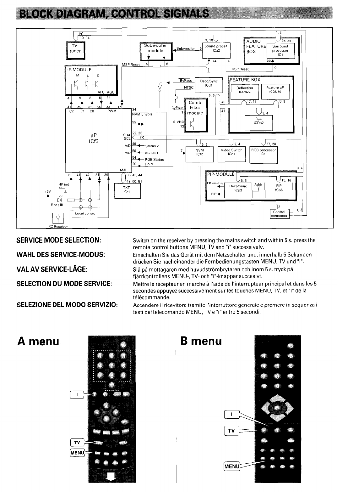
SERVICE MODE SELECTION:
WAHL DES SERVICE-MODUS:
VAL AV SERVICE-L2iGE:
SELECTION DU MODE SERVICE:
SELEZIONE DEL MOD0 SERVIZIO:
SDA
cc-
M3L 1
I
Switch on the receiver by pressing the mains switch and within 5 s. press the
remote control buttons MENU, TV and ‘7” successively.
Einschalten Sie das Gerat mit dem Netzschalter und, innerhalb 5 Sekunden
driicken Sie nacheinander die Fernbedienungstasten MENU, TV und “7.
Sla pa mottagaren med huvudstrombrytaren och inom 5 s. tryck pa
fjarrkontrollens MENU-, TV- och “i”-knappar succesivt.
Mettre le recepteur en marche a I’aide de I’interrupteur principal et dans les 5
secondes appuyez successivement sur les touches MENU, TV, et “i” de la
telecommande.
Accendere il ricevitore tramite I’interruttore generale e premere in sequenza i
tasti del telecomando MENU, TV e ‘7” entro 5 secondi.
J,
A menu
B menu
Page 3
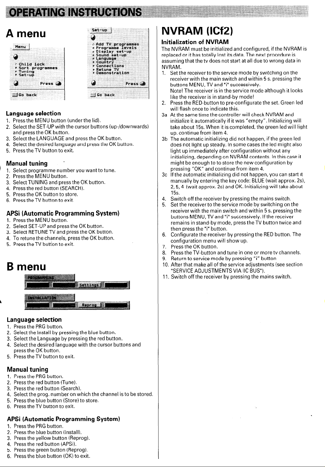
A menu
Language selection
1. Pressthe MENU button (under the lid).
2. Select the SET-UP with the cursor buttons (up-/downwards)
and press the OK button.
3. Select the LANGUAGE and press the OK button.
4. Select the desired language and press the OK button.
5. Press the TV button to exit.
Manual tuning ’
Select programme number you want to tune.
1.
1
Press the MENU button.
Select TUNING and press the OK button.
; :
4.
Press the red button (SEARCH).
Press the OK button to store.
5.
Press the TV button to exit.
6.
APSi (Automatic Programming System)
1. Press the MENU button.
2. Select SET-UP and press the OK button.
3. Select RETUNE TV and press the OK button.
4. To retune the channels, press the OK button.
5. Press theTV button to exit.
B menu
NVRAM (ICf2)
lnitialization of NVRAM
The NVRAM must be initialized and configured, if the NVRAM is
replaced or it has totally lost its data. The next procedure is
assuming that the tv does not start at all due to wrong data in
NVRAM.
1.
Set the receiver to the service mode by switching on the
receiver with the main switch and within 5 s. pressing the
buttons MENU, TV and “i” successively.
Note! The receiver is in the service mode although it looks
like the receiver is in stand-by mode!
2.
Press the RED-button to pre-configurate the set. Green led
will flash once to indicate this.
At the same time the controller will check NVRAM and
3a
initialize it automatically if it was “empty”. lnitializing will
take about 15s. When it is completed, the green led will light
up. continue from item 4.
The automatic initializing did not happen, if the green led
3b
does not light up steady. In some cases the led might also
light up immediately after configuration without any
initializing, depending on NVRAM contents. In this case it
might be enough to to store the new configuration by
pressing “OK” and continue from item 4.
If the automatic initializing did not happen, you can start it
3c
manually by entering the key code: BLUE (wait approx. 2~1,
2,5,4 (wait approx. 2s) and OK. lnitializing will take about
15s.
Switch off the receiver by pressing the mains switch.
4.
Set the receiver to the service mode by switching on the
5.
receiver with the main switch and within 5 s. pressing the
buttons MENU, TV and “i” successively. If the receiver
remains in stand-by mode, press the TV button twice and
then press the “i” button.
6.
Configurate the receiver by pressing the RED button. The
configuration menu will show up.
7.
Press the OK button.
Press the TV-button and tune in one or more tv channels.
8.
Return to service mode by pressing “i” button
9.
After that make all of the service adjustments (see section
10.
“SERVICE ADJUSTMENTS VIA IIC BUS”).
11.
Switch off the receiver by pressing the mains switch.
Language selection
1. Press the PRG button.
2. Select the Install by pressing the blue button.
3. Select the Language by pressing the red button.
4. Select the desired language with the cursor buttons and
press the OK button.
5. Press the TV button to exit.
Manual tuning
1. Press the PRG button.
2. Press the red button (Tune).
3. Press the red button (Search).
4. Select the prog. number on which the channel is to be stored.
5. Press the blue button (Store) to store.
6. Press the TV button to exit.
APSi (Automatic Programming System)
1. Press the PRG button.
2. Press the blue button (Install).
3. Press the yellow button (Reprog).
4. Press the red button (APSi).
5. Press the green button (Reprog).
6. Press the blue button (OK) to exit.
Page 4
SERVICE MODE SELECTION
1. The receiver is set to the service mode by switching on the
receiver with the mains switch and within 5 seconds pressing
the remote control buttons MENU, TV and “i” successively.
Note! If the receiver remains in stand by mode after selecting
the service mode, switch on the receiver by pressing the TV
button twice and select the service mode by pressing the 7”
button.
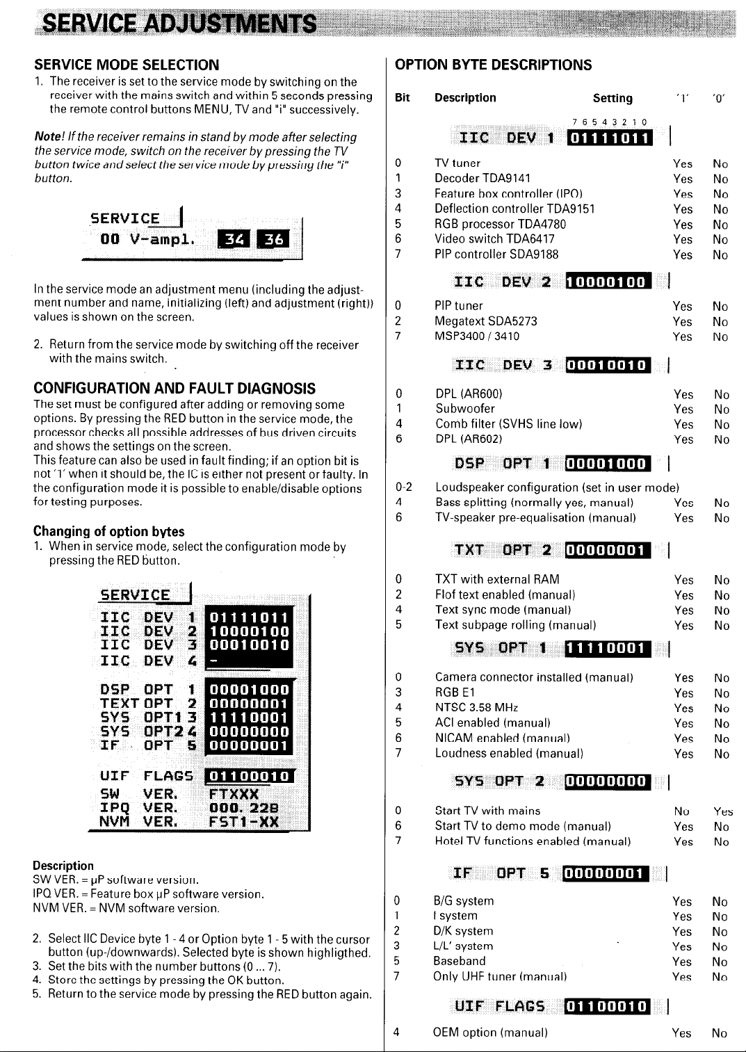
OPTION BYTE DESCRIPTIONS
Bit
Description Setting
76543210
IIC DEV 1 m
0 TV tuner
1
Decoder TDA9141
3
Feature box controller (IPQ)
4
Deflection controller TDA9151
5
RGB processor TDA4780
6 Video switch TDA6417
7
PIP controller SDA9188
, I
1
'0'
I
Yes No
Yes No
Yes No
Yes No
Yes No
Yes No
Yes No
In the service mode an adjustment menu (including the adjustment number and name, initializing (left) and adjustment (right))
values is shown on the screen.
2. Return from the service mode by switching off the receiver
with the mains switch.
CONFIGURATION AND FAULT DIAGNOSIS
The set must be configured after adding or removing some
options. By pressing the RED button in the service mode, the
processor checks all possible addresses of bus driven circuits
and shows the settings on the screen.
This feature can also be used in fault finding; if an option bit is
not ‘1’ when it should be, the IC is either not present or faulty. In
the configuration mode it is possible to enable/disable options
for testing purposes.
Changing of option bytes
1. When in service mode, select the configuration mode by
pressing the RED button.
IlC DEV 2
0 PIP tuner
2
Megatext SDA5273
7
MSP3400 / 3410
0 DPL (AR600)
1
Subwoofer
4
Comb filter (SVHS line low)
6
DPL (AR6021
DEjP WT 1 11111111It111111
O-2
Loudspeaker configuration (set in user mode)
4
Bass splitting (normally yes, manual) Yes No
6
TV-speaker pre-equalisation (manual)
TXT OPT 2 [~I~IWI~I~~ 1
0
TXT with external RAM Yes No
2
Flof text enabled (manual) Yes No
4
Text sync mode (manual) Yes No
5
Text subpage rolling (manual) Yes No
SYfi OPT 1
Camera connector installed (manual)
RGB El Yes
NTSC 3.58 MHz
ACI enabled (manual) Yes
NICAM enabled (manual)
Loudness enabled (manual) Yes
m
III11
UI
I
Yes No
Yes No
Yes No
Yes No
Yes No
Yes No
Yes No
I
Yes
Yes
Yes
Yes
No
No
No
No
No
No
No
Description
SW VER. = uP software version.
IPQVER. = Feature box uP software version
NVM VER. = NVM software version.
2. Select IIC Device byte 1 - 4 or Option byte 1 5 with the cursor
button (up-/downwards). Selected byte is shown highligthed.
3. Set the bits with the number buttons (0 7).
4. Store the settings by pressing the OK button.
5. Return to the service mode by pressing the RED button again.
l~lIl~l~l~l~l~l
sr!j OPT 2
0
Start TV with mains No
6
Start TV to demo mode (manual)
7
Hotel TV functions enabled (manual) Yes
IF
B/G system Yes
I system Yes
D/K system Yes
L/L’ system Yes
Baseband
Only UHF tuner (manual) Yes No
OF-f- 5 [IIIIIIIIIIIII~ 1
UIF FLAG5
OEM option (manual) Yes No
1
IIIIIJ[I
2
11
11
Yes
Yes
No
No
No
No
No
No
Yes No
Page 5
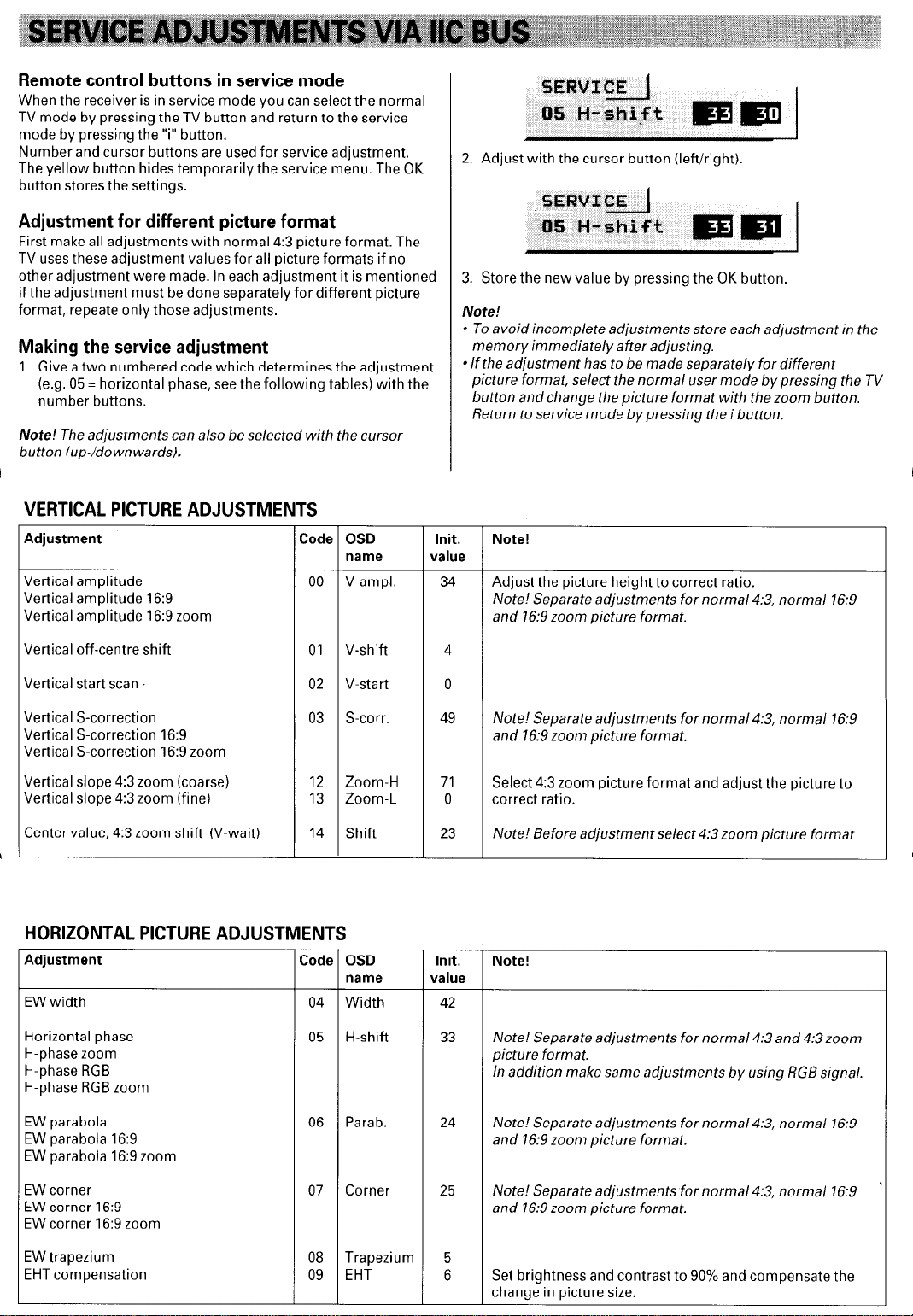
Remote control buttons in service mode
When the receiver is in service mode you can select the normal
TV mode by pressing the TV button and return to the service
mode by pressing the “i” button.
Number and cursor buttons are used for service adjustment.
The yellow button hides temporarily the service menu. The OK
button stores the settings.
Adjustment for different picture format
First make all adjustments with normal 4:3 picture format. The
TV uses these adjustment values for all picture formats if no
other adjustment were made. In each adjustment it is mentioned
if the adjustment must be done separately for different picture
format, repeate only those adjustments.
Making the service adjustment
1. Give a two numbered code which determines the adjustment
(e.g. 05 = horizontal phase, see the following tables) with the
number buttons.
Note! The adjustments can also be selected with the cursor
button (up-/downwards).
VERTICAL PICTURE ADJUSTMENTS
Adjustment
Vertical amplitude
Vertical amplitude 16:9
Vertical amplitude 16:9 zoom
Code OSD
name
00 V-ampl.
2. Adjust with the cursor button (left/right).
3. Store the new value by pressing the OK button
Note!
l To avoid incomplete adjustments store each adjustment in the
memory immediately after adjusting.
l If the adjustment has to be made separately for different
picture format, select the normal user mode by pressing the TV
button and change the picture format with the zoom button.
Return to service mode by pressing the i button.
Init. Note!
value
34 Adjust the picture height to correct ratio.
Note! Separate adjustments for normal 4:3, normal 16:9
and 16:9 zoom picture format.
Vertical off-centre shift
Vertical start scan.
Vertical S-correction
Vertical S-correction 16:9
Vertical S-correction 16:9 zoom
Vertical slope 4:3 zoom (coarse)
Vertical slope 4:3 zoom (fine)
Center value, 4:3 zoom shift (V-wait)
01 V-shift
02 V-start
03 S-corr.
12 Zoom-H
13 Zoom-L
14 Shift
HORIZONTAL PICTURE ADJUSTMENTS
Adjustment
EW width
Horizontal phase
H-phase zoom
H-phase RGB
H-phase RGB zoom
EW parabola
EW parabola 16:9
EW parabola 16:9 zoom
Code OSD
04 Width
05 H-shift
06 Parab. 24
name
4
0
49 Note! Separate adjustments for normal 4:3, normal 16:9
and 16:9 zoom picture format.
71
23 Note! Before adjustment select 4:3 zoom picture format
Init.
value
42
33
Select 4:3 zoom picture format and adjust the picture to
0 correct ratio.
Note!
Note! Separate adjustments for normal 4:3 and 4:3zoom
picture format.
In addition make same adjustments by using RGB signal.
Note! Separate adjustments for normal 4:3, normal 16:9
and 16:9 zoom picture format.
EW corner
EW corner 16:9
EW corner 16:9 zoom
EW trapezium
EHT compensation
07 Corner 25 Note! Separate adjustments for normal 4:3, normal 16:9
and 16:9 zoom picture format.
08 Trapezium 5
09 EHT 6 Set brightness and contrast to 90% and compensate the
change in picture size.
Page 6
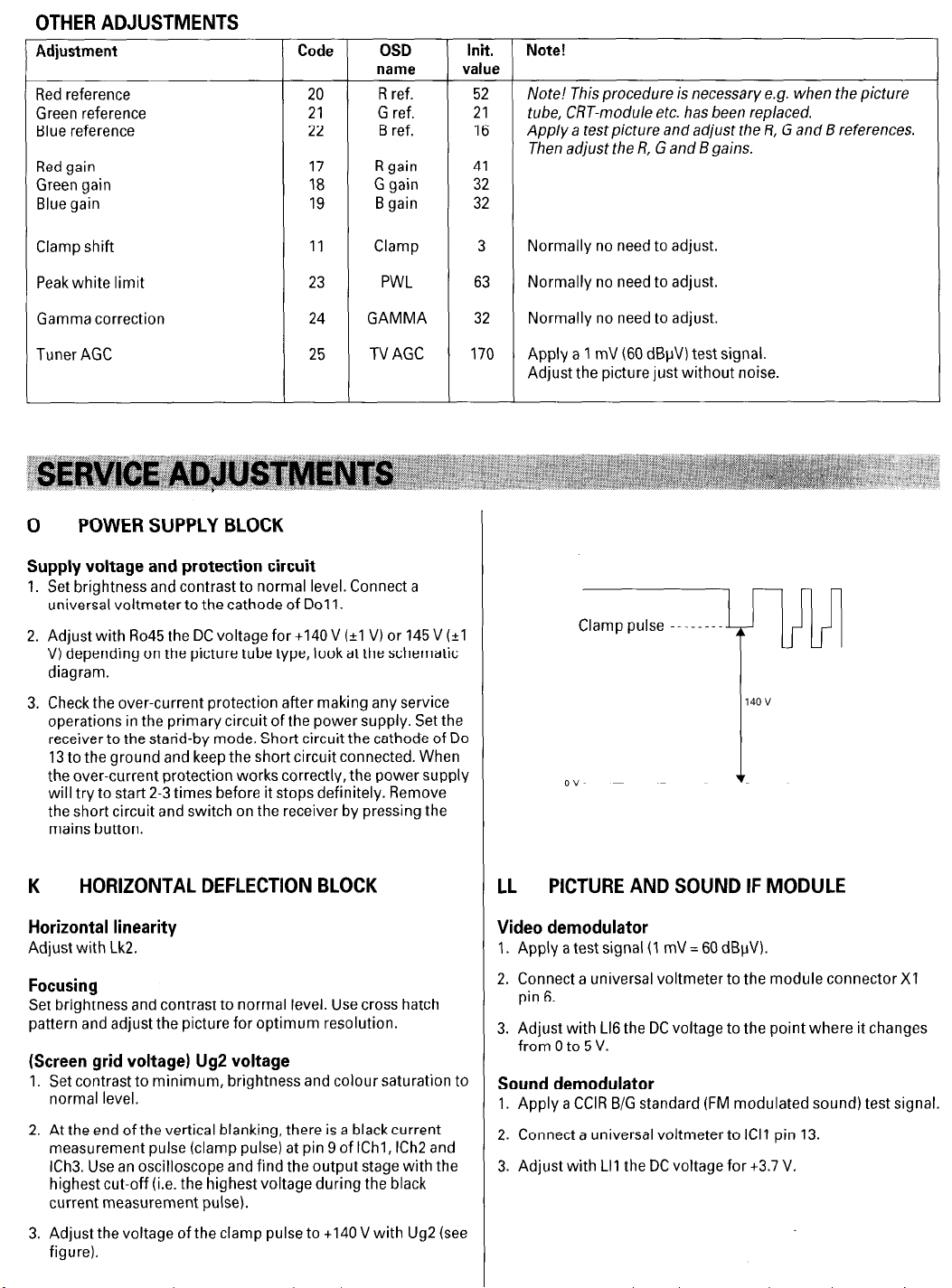
OTHER ADJUSTMENTS
Adjustment
Red reference
Green reference
Blue reference
Red gain
Green gain
Blue gain
Code
20
21
22
17
18
19
OSD
name value
R ref. 52
G ref.
B ref. 16
R gain
G gain 32
B gain 32
Init. Note!
21 tube, CRT-module etc. has been replaced.
41
Note! This procedure is necessary e.g. when the picture
Apply a test picture and adjust the R, G and B references.
Then adjust the R, G and B gains.
Clamp shift
Peak white limit
Gamma correction
Tuner AGC
11
23
24
25
Clamp 3
PWL 63
GAMMA 32
TV AGC 170
0 POWER SUPPLY BLOCK
Supply voltage and protection circuit
Set brightness and contrast to normal level. Connect a
universal voltmeter to the cathode of Do1 1.
Adjust with Ro45 the DC voltage for +I40 V (*I V) or 145 V (*I
V) depending on the picture tube type, look at the schematic
diagram.
Check the over-current protection after making any service
operations in the primary circuit of the power supply. Set the
receiver to the stand-by mode. Short circuit the cathode of Do
13 to the ground and keep the short circuit connected. When
the over-current protection works correctly, the power supply
will try to start 2-3 times before it stops definitely. Remove
the short circuit and switch on the receiver by pressing the
mains button.
Normally no need to adjust.
Normally no need to adjust.
Normally no need to adjust.
Apply a 1 mV (60 dBpV) test signal.
Adjust the picture just without noise.
Clamp pulse --------
4-P
140v
1
HORIZONTAL DEFLECTION BLOCK
Horizontal linearity
Adjust with Lk2.
Focusing
Set brightness and contrast to normal level. Use cross hatch
pattern and adjust the picture for optimum resolution.
(Screen grid voltage) Ug2 voltage
Set contrast to minimum, brightness and colour saturation to
normal level.
At the end of the vertical blanking, there is a black current
measurement pulse (clamp pulse) at pin 9 of IChl, ICh2 and
ICh3. Use an oscilloscope and find the output stage with the
highest cut-off (i.e. the highest voltage during the black
current measurement pulse).
Adjust the voltage of the clamp pulse to +I40 V with Ug2 (see
figure).
PICTURE AND SOUND IF MODULE
LL
Video demodulator
1. Apply a test signal (1 mV = 60 dBpV).
2. Connect a universal voltmeter to the module connector Xl
pin 6.
3. Adjust with Ll6 the DC voltage to the point where it changes
from 0 to 5 V.
Sound demodulator
1. Apply a CCIR B/G standard (FM modulated sound) test signal.
2. Connect a universal voltmeter to ICI1 pin 13.
3. Adjust with LII the DC voltage for +3.7 V.
Page 7
Page 8
Page 9
Page 10

Page 11

Page 12

Page 13

Page 14

Page 15

Page 16

Page 17

Page 18

Page 19

Page 20

Page 21

Page 22

Page 23

Page 24

Page 25

Page 26

Page 27

 Loading...