


Ersatzteile Replacem Pièces de Pezzi di ric
TV 048 1991
25
NOKIA UNTERHALTUNGSELEKTRONIK GmbH D-7530 Pforzheim
Service-Manual
57
DIGIVISION 6362 Ident-No. 5438 71 50
DIGIVISION 6382 Ident-No. 5438 71 60
DIGIVISION 7162 Ident-No. 5438 71 70
DIGIVISION 7182 Ident-No. 5438 71 80
SALORA
21 N 6 Ident-No. 5435 30 20 / 5437 79 90
25 N 6 Ident-No. 5435 32 80 / 5437 80 20
Eine Kurzbedienungsanleitung finden Sie auf dem Manualblatt A 28.2 . You will find a short set of operating instructions on the manual sheet A 28.2 . Un mode d'emploi abrégé figure sur la feuille A 28.2 du manuel. Brevi istruzioni per l'uso si trovano sul foglio A 28.2 .
Zur Reparatur sind folgende Unterlagen erforderlich: For service, the following circuit documents are required: Voici les documents nécessaires pour le dépannage: Per la riparazione sono necessari i sequenti documenti:
M 891 M 891
Bildröhrenanschluß / C.R.T. base board Connexion tube image / Collegamento cinescopio 6911 08 78
| N |
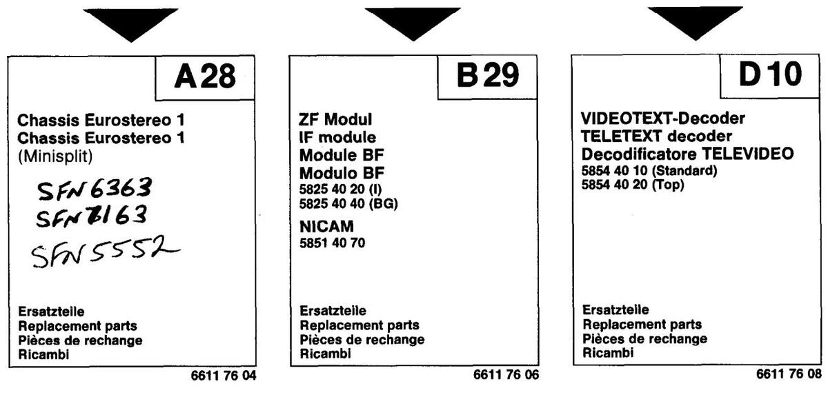
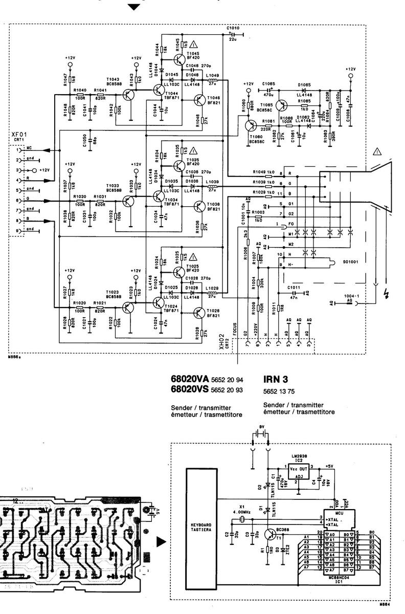
Chassis Eurostereo 1
5864 40 10 (90°) 5864 40 20 (110°) FST 28 kV 5864 40 11 (90°) Minisplit 5864 40 21 (110°) Minisplit FST 28 kV |
A 28 | |
|---|---|---|---|
|
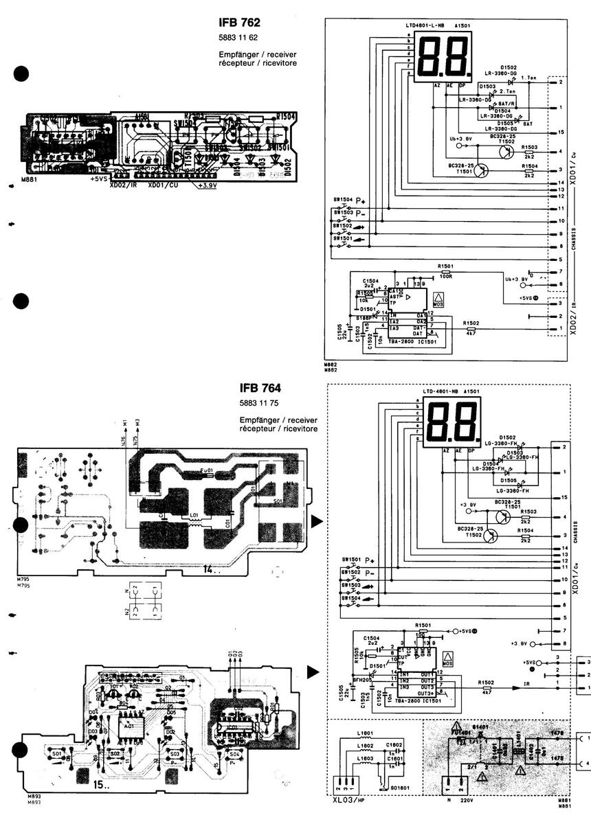
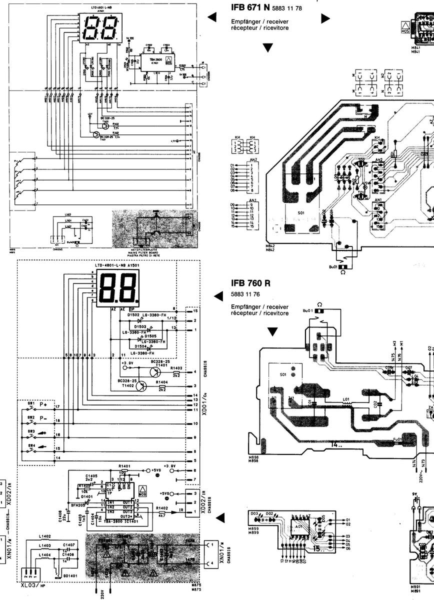
FB 760 5883 11 76
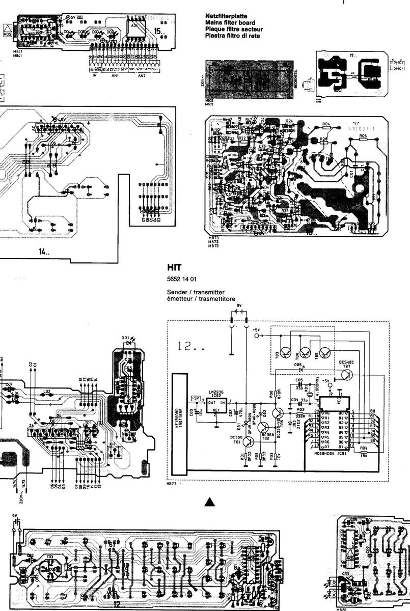
FB 762 5883 11 62 FB 764 5883 11 75 FB 671 5883 11 78 RN 3 5652 13 75 / HIT 5652 14 01 80 20 VA 5652 20 94 80 20 VS 5652 20 93 |
BCL 6911 33 20
Bildröhrenanschlußplatte 6911 08 7 C.R.T. base board Platine-connexion tube-cathodiqu Piastra di allac. del cinescopio |
78
ue |
|
|
Achtungi
Röntgenv gewährlei: minimalen Warningi X-ray regu high-volta minimum Attentiont Réglemer tube-imag tension di contrôlée Attenzione Regolame tensione r minima ca |
Bei Reparaturen gültige Sicherheitsvorschriften beachte
erordnung: Die in der Röntgenverordnung festgelegte C stet. Die Hochspannung darf maximal 28 kV betragen. Di n Strahlstrom 145 V (110°) 130 V (90°) beträgt. Bei Repara For repair works adhere to existing safety regulations. Jletions: The picture tube type and the maximum permis ge must not exceed 28 kV. The high voltage is within the pei beam current. Following servicing, check and adjust this v En cas de réparations, tenir compte des règles de sécu tetion portant sur les rayons X: La puissance de dose loc et à la haute tension maximale admissible. La haute tensi e service de l'étage de convergence horizontale s'élève et et, le cas échéant, être ajustée sur la valeur de consigne e el Per riparazione fare attenzione alle valevoii prescrizior nto raggi X: La potenza prevista dall disciplina raggi X pe massima deve comportare 28 kV max. La tensione massim todica 145 V (110°) 130 V (90°). Controllare, in caso di ripa |
n.
Prtsdosisleistung ist bei diesem Gerät durch die Bildröhrentype und die maxi re Hochspannung liegt im zulässigen Bereich, wenn die Betriebsspannung di turen ist die Spannung zu überprüfen und gegebenenfalls mit R 754 auf Sollwe sible high-voltage ensure that the X-ray intensity within the set remains far bei rmissible limits when the operating voltage of the horizontal deflection stage equ oltage to the nominal value with R 754. Irité en vigueur. ale fixée dans la réglementation relative aux rayons X est garantie dans le cas de on ne doit pas dépasser un maximum de 28 kV. La haute tension se situe dans le à 145 V (110°) 130 V (90°) pour un courant de faisceau minimal. En cas de ré au moyen de R 754. I di sicurezza. Ir questo genere di apparecchio viene garantita dal tipo di cinescopio e dalla ter la tensione, la tensione, e, all'occorrenza, mettere a punto, a valore nominale, me |
imal zulässige Hochspannung
ler Horizontal-Ablenkstufe bei ert einzustellen. ow the permissible value. The Jals 145 V (110°) 130 V (90°) at e cet apparell grâce au type de Jne zone admissible lorsque la sparations, la tension doit éte esione massima consentita. La izzontale comporta a corrente diante R 754. |
|
Erläut
Légen |
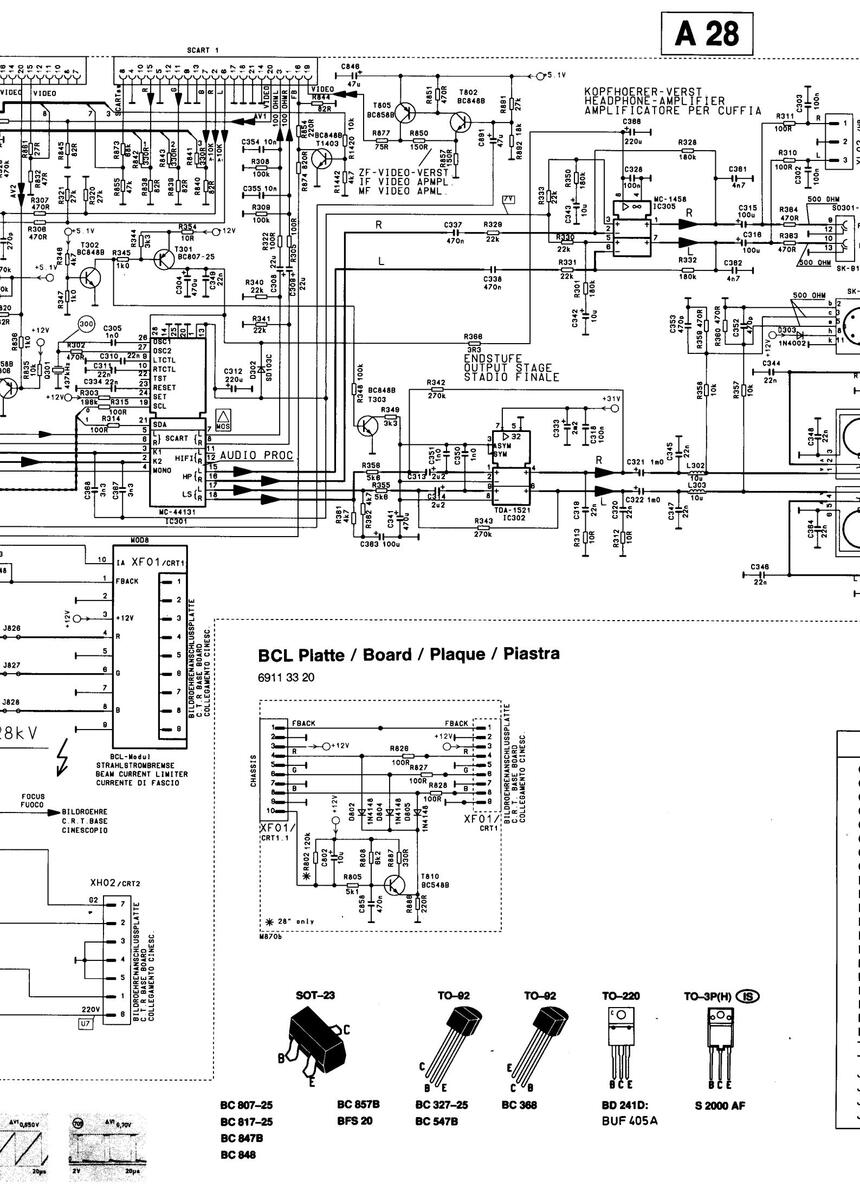
erungen zu den Schaltbildern / Cir
des des schémas / Spiegazioni de Vert. Imp. / Vert. imp. / Impulsion vert. / Impulso ver Hor. Imp. / Hor. Imp. / Impulsion hor. / Impulso orizz NE-Sign / AE sign / BE / BE |
cuit diagram legend
i simboli usati sullo schema t. z. |
|
|
FBAS-Sign. / Comp. colour signal / CLSS / CLSS
Testpunkt. Test point. Point test. Punto di controllo |
|||
| ///// |
Schaltnetzteil-Minuspotential / Switch-moded power
Rapport au potentiel négatif du bloc-d'alimentation à |
· supply minus potential /
à découpage / Collegamento della sezione di rete a potenziale negativo |
|
|
Messungen auf ⊥ (Masse) bezogen / Measurement
Toutes les mesures se rapportent à la masse / Rifer |
ts referenced to earth (⊥) /
ire tutte le misure alla massa |
||
|
Messungen auf Schaltnetzteil-Minuspotential bezog
Toutes les mesures se rapportant au potentiel négat Riferire tutte le misure al potenziale negativo della se |
an / Measurements referenced to switch-moded power supply minus po
tif du bloc-secteur de commutation ezione di rete |
tential / | |
| Q |
Oszillogramm-Meßpunkt auf ⊥ (Masse) bezogen / V
Tous les oszillogrammes se rapportant à la masse / |
Vaveforms referenced to earth (⊥) /
Riferire tutti gli oscillogrammi alla massa |
|
| Q |
Oszillogramm-Meßpunkt auf
1
/
1
(Masse an IC 701 Pin 1
Tous le oszillogrammes se rapportant au 1 / 1 (la masse IC |
i ect.) bezogen / Waveforms referenced to
(earth on IC 701 Pin 1 ect.) /
701 Pin 1) / Riferire tutti gli oscillogrammi al (alla massa IC 701 Pin 1) |
|
|
Sicherheitsbautell im Sinn der Sicherheitsbestimmung. D
Safety components in accordance with existing regulatio Composant de sécurite en accordance ayec les régulati omologato in base alle norme di sicurezza. Questi pezzi |
Nese Teile dürfen nur durch Originalteile ersetzt werden.
ns. These components must only be replaced by original component parts. ons existantes. Ces composants diovent être remplacés par des composants devono essere sostituit soltanto con pezzi originali. |
origin
|
|
|
R
100 |
Chip-Widerstand / Resistor / D | ||
|
C
100 |
Chip-Kondensator / Capacitor / E
Condensateur-chip / Condensatore |
B
Chip-Transistor |
|
|
L
100 |
Chip-Spule/Drossel / Coil/Choke / C
Bobine/self-chip / Bobina |
||
|
Br
100 |
Chip-Brücke / Jumper /
Shunt-chip / Ponte |
•
• |
|
|
Schutzmaßnahmen für MOS-Baueleme
Pay attention to protective measures Respecter les mesures de protections Osservare le misure protettive per gli |
ente beachten!
for MOS components! s pour les composants de MOS! elementi costruttivi MOS! |
When re-ordering manuals, please quote the model name and part number. En cas de commande supplémentaire de manuels veuillez indiquer le type et le numéro de l'appareil. Per riordinare i manuali, indicare il modello dell'apparecchio ed il numero categorico.
Eurostereo Chassis 1
Wave forms at normal operatio Oscillogrammes en mode de fo Oscillogrammi in presenza di e
Achtung! Die Oszilloscopmasse muß in der Nähe der zu mess den Baugruppe angeschlossen werden.
N.B.! The oscilloscope frame must be connected near the me being measured
Attention! La masse de l'oscilloscope doit être raccordée à proximité du module devant être mesuré. La massa dell'oscilloscopio deve essere collegata vicino a componente da misurare.
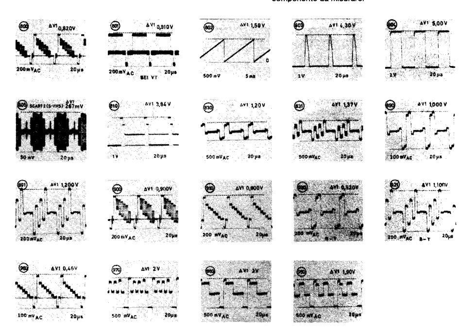
Alle Decoderoszillogramme sind unter folgenden Bedingungen aufgenommen: Normfarbbalken PAL, maximaler Kontrast.ca. Nennhelligkeit und nominale Sättigung.
The decoder waveforms are taken under following conditions: Standard PAL that is, contrast at maximum and brightness and colour saturation at nominale value.
Tous les oscillogrammes mesurés sur le décodeur sont pris sous les conditions suivantes: Norme de mire de barre PAL, contrast au maximum, luminosité et intensité couleur aux valeurs
Tutti gli oscillogrammi decoder sono stati fatti nelle seguenti condi-zioni: generatore di barre PAL, massimo contrasto, approssimativamente luminosità e saturazione normali.
Achtung! Nach Austausch von T 701 muß auch IC 701 ausgewechselt werden. Important!
When exchanging T 701, IC 701 must likewise be exchanged.
Attention!
En changeant le T 701 il faut remplacer aussi le Cl 701.
Attenzione!
Durante la sostituzione di T 701 deve essere sostituito anche IC 701.
| ★ Pos. | 90° Chassis 5864 40 10 | 110° Chassis 5864 40 20 | |
|---|---|---|---|
| C 405 | 2,2 μF | 3,3 μF | |
| C 502 | 4,7 nF | 3,3 nF | |
| C 507 | 6,8 nF | 8,2 nF | |
| C 508 | 47 nF | 27 nF | |
| C 513 | 0,18 μF 250 V | 0,18 μF 400 V | |
| C 514 | 180 nF | 120 nF | |
| C 518 | 220 nF | 220 nF | |
| C 519 | 1,5 nF | 1,5 nF | |
| R 403 | 2,2 kΩ | 1,2 kΩ | |
| R 410 | — | 1,5 Ω | |
| R 411 | 1,5 Ω | 1,2 Ω | |
| R 505 | 1 kΩ | ່ 1 kΩ | |
| R 520 | 1 MΩ | 2 MΩ | |
| R 531 | 750 kΩ | 270 kΩ | |
| R 540 | J 540 | J 540 | |
| R 726 | 4,7 kΩ | 4,7 kΩ | |
| R 758 | 43 kΩ | 59 kΩ | |
| L 502 | 75 μH | 100 µH | |
| L 505 | Lin. 4516 1203 | Lin. 4516 1201 | |
| L 506 | O-W 4517 2492 | O-W 4517 2491 | |
| Tr 501 | 4515 0503 | 4515 0503 | |
| Tr 703 | 4523 1583 | 4523 1580 | |
| J 507 | - | - | |
| , J 540 | J 540 | J 540 | |
| J 906 | J 906 | — (J 1006) | |
| J 1006 | — (J 906) | J 1006 | |
| 116 | |||
|---|---|---|---|
| ≭ REF : | 58644011 | 58644021 | |
| C405 | 575 | 3u3 | |
| C502 | 4n7 | 4n7 | |
| C507 | 6n8 | 8n2 | |
| C508 | 47n | 27n | |
| C514 | 180n | 120n | |
| C518 | 150n | 120n | |
| C519 | 1n5 | ln3 | |
| L502 | 75u | 75u | |
| 8403 | 2k2 | 1 k | |
| 8411 | 185 | 1k2 | |
| 8505 | 33R | 39A | |
| R520 | 1M0 | 2M0 | |
| 8531 750k | 270k | ||
| R726 | 2k2 | 4k7 | |
| 8758 | 43k | 59k | |
| A804 | 9k 1 | 15k | |
| R807 | 9k 1 | 8k2 | |
| 8884 | 15k | 3k 0 | |
| TR501 | M10_02 | M10_01 | |
| J207 | YES | TES |
|---|---|---|
| 1540 | - | 1 |
| 1906 | YES | - |
| J1006 | - | TES |
| R540 | 183 | 183 |
| D Servi | ce-Abgleich / @B Servi | ce Cali | ibration | ||||
|
1. Mit Hilfe des Fernbec
In service mode, vou |
tienungsgebers können Sie im Service-Mode Geom
can use the remote control transmitter to set geom |
etrie, Lumina |
nz- und Stereowerte einstellen und die Optionsbits setzen.
se and stereo values, and the option bits. |
||||
|
|||||||
|
Weitere Tastenfunktie
Taste / button "STEP |
onen im
Service Mode:
/ Further button functions in
+ |
service mode |
e:
il: TV-Taste drücken: Vorderteil nach oben kippen "+" (nach unten "-"). |
||||
| Taste / button ,VOLU |
= switching over from calibration to calibratio
IME" = Wertveränderung + = altering value(s) |
on, with a HII | oper. panel: press IV button, hold front part upwards "+" (downwards "-"). | ||||
| Taste / button "0…9 |
|
mit Program |
mwahitaste
button |
||||
|
Taste / button "●" (P
Taste / button "U" |
rogr.) = Memory
= Service-Mode verlassen |
||||||
| = Exit Service Mode | |||||||
| OSD | Funktion / Function | Display | Bemerkung / Remarks | ||||
|
U
I
mit R 754
auf 145 V (110
Set U I to 145 V (110°) 130 |
0°) 130 V (90°) bei
0
+ ∹O÷ = min. einstellen.
V (90°) at 0 + ∹O÷ = min., using R 754. |
||||||
| 0 (V.AMP) |
Vert Ampl.
Vert. ampl. |
00 |
OSD = On Screen Display = Bildschirmanzeige
OSD 0 bis OSD 13 bei FUBK-Testbild o. ä. einstellen |
||||
| 1 (V.LIN) |
Vert. Lin.
Vert. lin. |
01 |
OSD = On Screen Display
Set OSD 0 to OSD 13 in FUBK test picture (or similar) |
||||
| 2 (S.COR) |
o. Funktion
Special function |
02 | |||||
| 3 (V.POS) |
Vert. Lage
Vert. position |
03 | |||||
|
OSD 0 bis OSD 3 müssen
OSD 0 to OSD 3 must hav |
eingestellt sein.
e been set. |
||||||
| 4 (H.POS) | Hor. Lage | 04 | |||||
| 5 (H.AMP) |
Hor, Amp.
Hor, ampl. |
05 | |||||
| 6 (P.TILT) |
O-W Trapez
Keystone |
06 | |||||
| 7 (P.AMP) |
O-W Kissen
O-W pincushion |
07 | |||||
| 8 (P.CORN) |
O-W Eckenkorrektur
Corner correction |
08 | |||||
|
Focus mit R 500 Focus au
Set focus to optimum defi |
f optimale Schärfe einstellen.
nition using R 500 focus. |
||||||
| G2- und Farbtemperatur | |||||||
|
Rot-Drive (OSD 10) und Blau-Drive (OSD 11) mit der
Nennhelligkeit (der Schwarzbalken der Grautrenne |
"Volume"-T a | ste jeweils den OSD-Wert von 032 einstellen. R 500 G2 -Einsteller auf Mittenstellung. | ||||
|
Bildröhrenkathoden (R,
– im Rot-Drive (OSD 10) u |
G, B) ermitteln. Mit R 500 G2-Einsteller den Wert die
nd Blau-Drive (OSD 11) mit -Volume"-Taste in den h |
ser Kathode |
auf 168 V (gemessen gegen Massel) einstellen, oder bei Tastkopf 10: 1 = 163 V einst.
auf farbneutrales Bild einstellen |
||||
|
G2- and colour temperatu
Grey-scale test picture or |
re
similar. |
||||||
|
in each of the following drives: in the green drive (O
tness adjuster to rated brightness (the black bar of |
SD 9), red dri
the grey scale |
ve (OSD 10) and blue drive (OSD 11), using the "Volume" button. R 500 G2 adjuster to its
e must just not be lit up!). Use an oscilloscope (Probe 100:1) to determine the highest black |
||||
|
value at the picture-tube
— Use the "Volume" buttor |
e cathodes (R, G, B). Use the
R 500 G2
adjuster to see
In to adjust to a colour-neutral picture in the light area |
et this value to
as in red drive |
• 168 V (measured against ground), or probe 10:1 = 163 V. • (OSD 10) and blue drive (OSD 11). | ||||
| 12 (V.BRE) |
Bildamplitudenstab.*
Pict. ampl. stab.* |
12 | |||||
| 13 (LUM.DEL) |
Luminanz-Laufzeit
Luminance delay time |
13 | |||||
| 14 (AUDIO) |
Stereo-Ubersprechen
Stereo crosstalk |
| 14 |
1 kHz-Stereo-Signal anlegen. Linker Kanal ohne Modulation. Oscilloscop an
SCART-Buchse Pin 3. Mit Volume-Taste Wert auf Minimum einstellen. |
||||
|
Connect a 1-kHz stereo signal. Left channel without modulation. Oscilloscop to SCART
socket pin 3. Set value to minimum, using the volume button. |
|||||||
|
t. Ampl. bei
0 + ∹0∵ =
max. einstellen, dann
0 + ∹
h OSD 12 durchgeführt werden. |
0÷ soweit zur | ückstellen, bis das Bild gerade noch erkennbar ist. Sollte sich nun die vert. Ampl. verändert | ||||
|
ity. Set vertical amplitude at
O
+ →O÷ = max., then r
ion procedure OSD 12. |
eset 0 + ∹O ⊱ | until the picture is just still recognizable. If now the vertical amplitude turns out to have | ||||
|
Die Optionsbytes sind bei
Set the option bytes anew |
Austausch des EEPROM'S neu einzustellen (siehe
after you have replaced the EEPROM (see section |
e nächste Se
n "setting the |
te Kapitel "Setzen der Optionsbytes").
option bytes"). |
||||
| n der Optionsbytes / GB | Setti | ng the option bytes | |||||
| Übersich | nt | Survey | |||||
| OSD | Funktion / Function | Display | Bemerkung / Remarks | ||||
| 15 (OPBYT 1) | Optionsbyte 1 | 15 | bit 1 bit 0 = 1 | ||||
| 16 (OPBYT 2) |
Option byte 1
Optionsbyte 2 |
R S | 6 7 2 bit 1 = 2 im Optionsbyte 1 leuchtet z.B. | ||||
| 17 (OPBYT 3) |
Option byte 2
Optionsbyte 3 |
38 |
bit 3 = 8 bit 1 + bit 6
bit 4 = 16 bit 1 = 2 |
||||
| 18 (PR LOCK) |
Progr. Sperbyte
Progr. lock byte |
18. |
bit 5 = 32
bit 6 = 64 c 5 = 5 |
||||
| 19 (RESERVE) |
Res. Byte
Res. byte |
19 | 4 bit 0 bit 7 = 128 030 - 000 - 3atomptimer + 011 | ||||
| Option Byte 1 | 4 | ||||||
|
Bit/bit1 Bit/bit0
▼ ▼ |
|||||||
|
Bit 0 / bit 0
Bit 1 / bit 1 |
Empfangsteile 1 0 = Salcomp | ||||||
|
Bit 2 / bit 2
Bit 3 / bit 3 Bit 4 / bit 4 |
Neine Anzeige aurch Leuchtalode / No LED-display | ||||||
|
Bit 5 / bit 5
Bit 6 / bit 6 |
• | ||||||
| Bit 7 / bit 7 | |||||||
|
Option Byte 2
Bit 0 / bit 0 |
|||||||
|
Bit 1 / bit 1
Bit 2 / bit 2 |
Keine Anzeige einer gesendeten Textnachricht (F | =LOF) / No di | splay of text broadcast message (FLOF) | ||||
|
Bit 3 / bit 3
Bit 4 / bit 4 |
Bit 3 / bit 3 OSD-Synchronisation / Alternative OSD sync. O = Y2 1 = RGB Bit 4 / bit 4 Standby-Schaltung, wenn kein Signal (sleep timer) / Timeout to stand-by if no signal (sleep timer) | ||||||
|
Bit 5 / bit 5
Bit 6 / bit 6 Bit 7 / bit 7 |
Iastatur-Uberwachung / Monitor keyboard
Vertikale Zeitkonstante / Vertical time constant 0 = 8μs 1 = 24μs Maximaler Lautstärkewert minus 10 dB / Max volume value 10 dB Jourge |
||||||
| Option Byte 3 | |||||
|---|---|---|---|---|---|
|
Bit 0 / bit 0
Bit 1 / bit 1 Bit 2 / bit 2 Bit 3 / bit 3 Bit 4 / bit 4 Bit 5 / bit 5 Bit 6 / bit 6 Bit 7 / bit 7 |
C4-Bit erkennt die Ton-Norm* / C4-bit changes the sound*
Identifikationsbyte. Wird als Startregister benutzt. / Identification byte used as startup register PROG-Knopf schaltet das Bild ab / PROG-button switches off the picture Keine OSD-Anzeige von Programmnummern / No OSD-indication of programme numbers |
||||
|
Byte zum Sperren des Pro
Bietet die Möglichkeit zum O = Keine Position gesch angezeigt wird oder die n Program Lock Byte Offers the possibility to pri positions locked. Example bit 4, bit 3 and bit 1 (16+ |
Sperren des Programmiermodus. Der Dezimalwert dieses Bytes (auf dem Bildschirm angezeigt), gil
ützt. Beispiel: Sie möchten die ersten 26 Programmnummern sperren. Sie können entweder den L imerischen Tasten Bit 4, Bit 3 und Bit 1 (16 + 8 + 2 = 26). event access to the programming mode. The decimal value of the byte (shown on screen) indicates ti if you wish to lock the first 26 program numbers. You can either use the volume button and step unt 8 + 2). |
bt die letzte zu
autstärkekno he last progra il 26 is shown |
u sperren
pf drücke mme nun on screer |
de Programmnumn
en bis 26 auf dem E nber to be locked (1 n or use the numeric |
ner an (1-59).
Bildschirm (59). O = No cal keys to set |
|
Byte reserviert für identifi
Dieses Byte ist frei belegt Byte Reserved for identifi This byte is free for any d |
kationscode
nar für jeden Händler als Identifikationscode o.ä. (Wenn bei Option byte 3 Bit 1, Bit 1 auf 1 gesetzt cation Code paler to use as an identification code or similar. (When option byte 3 Bit 1 is set (1), this register is |
wird, wird die
used as start |
ses Regis
tup regist |
ster als Startregiste
er). |
ər benutzt. |
|
Inhalte des NICAM- und FM-Sound gleich sind. Wenn bei Option Byte 3 Bit 0, Bit 0 auf 1 gesetzt wir
Empfang voneinander abweichen. contents of the NICAM- and FM-sound are the same. When option byte 3 Bit 0 is set to 1, the TV-set |
d, schaltet da
will automatic |
is Fernsel
cally chan |
hgerät automatisch
ge to FM-sound wh |
auf FM-Sound um |
|
D Setze
z. B. nach Einsatz eines e.g. after the EEPROM |
EPROM's, das leer oder nicht auf den entsprechenden Tuner vorprogrammiert ist oder nach aus
nas been replaced (if it is empty or if it has not been preprogrammed for the appropriate tuner!) |
rtes
week des?tur ter Hustyder) |
|||
| Service-Mode in 1 Sec.: 1 | Taste -/ 2) Taste "MENÜ" 3) Taste 🗔 TV | Display | OSD |
Bemerkung
Remarks |
|
|
OSD-Anzeige sktiviere
Activate OSD display (N 1.1 In Service-Mode ge Go to service mode 1.2 Taste STEP. ¬¬¬¬" Press the STEP "¬ 1.3 Mit der Programm Use the channel me 1.4 Programmspeichele Press channel butt 2.5 1.1 Lact SUT# ar af 1.2 Support of the service 2.5 1.2 Support of the service 2.5 |
a (VT-Decoder muß eingesteckt sein!)
T decoder must be plugged in!) hen. - * drücken, bis im Display ≥ erscheint. - * button four times until ≥ appears in the display. anhtaste _3* bit 3 einschalten. mory button *3* to switch on bit 3. taste ● (bei HIT-Bedienteil: Rot-Taste) und dann Stand-by © drücken (Werte abgespeichert). on ● (with a HIT-oper, panel: red button), then *Stand-by © drücken (Werte abgespeichert). on ● (with a HIT-oper, panel: red button), then *Stand-by © drücken (Standard Standard) = Standard & Meditar standard & Meditar Standard Hit Market Berger (Standard) = Standard & Meditar Standard Hit Market Berger (Standard) = Standard & Meditar Standard Hit Market Berger (Meditar standard) = Standard & Meditar Standard Hit Market Berger (Meditar standard) = Standard & Meditar Standard Hit Market Berger (Meditar standard) = Standard & Meditar Standard Hit Market Berger (Meditar standard) = Standard & Meditar Standard Hit Market Berger (Meditar standard) = Standard & Meditar Standard Hit Meditar (Meditar standard) = Standard Hit Meditar (Meditar standard) = Standard Hit Meditar (Meditar standard) = Standard Hit Meditar (Meditar standard) = Standard Hit Meditar (Meditar standard) = Standard Hit Meditar (Meditar standard) = Standard Hit Meditar (Meditar standard) = Standard Hit Meditar (Meditar standard) = Standard Hit Meditar (Meditar standard) = Standard Hit Meditar (Meditar standard) = Standard Hit Meditar (Meditar standard) = Standard Hit Meditar (Meditar standard) = Standard Hit Meditar (Meditar standard) = Standard Hit Meditar (Meditar standard) = Standard Hit Meditar (Meditar standard) = Standard Hit Meditar (Meditar standard) = Standard Hit Meditar (Meditar standard) = Standard Hit Meditar (Meditar standard) = Standard Hit Meditar (Meditar standard) = Standard Hit Meditar (Meditar standard) = Standard) = Standard Hit Meditar (Meditar standard) = Standa |
880
280 210 210 210 210 |
and a second secon |
nur Display beac
Observe only the min. bit 3 muß le Bit 3 at least mus |
hten!
• display! uchten1 st be lit up! |
|
3. Mit Taste STEP "△+* a
Use the STEP "△+" bu |
ur OPBYT 2 schalten. Mit laste " — aur OSD 088 stellen.
tton to switch to OPBYT 2. Use button " — " to set to OSD 088. |
2'' , a | 088 | ||
|
uf OPBYT 3 schalten. Mit Taste , — auf OSD 001 stellen.
tton to switch to OPBYT 3. Use button " — to set to OSD 001. |
38 . | 001 | ||
|
uf PR LOCK schalten. Mit Taste , and auf OSD 000 stellen.
tton to switch to PR LOCK. Use button "and" to set to OSD 000. |
/ 8 | 000 | ||
|
6. Mit Taste STEP ,△+ * auf
RESERVE
schalten. Mit Taste , → * auf
OSD 000
stellen.
Use the STEP *△+ * button to switch to RESERVE . Use button * → * to set to OSD 000 . |
|||||
| 7. Werte abspeichern (sie | he Pkt. 1.4) / Storë values in memory (see Section 1.4) | ||||
|
8. Annanernde Os
Approximate O |
SD values for geometry, luminance and stereo. Go to service mode!) | ). |
OSD
90° (55 cm) |
OSD
110° (63+71 cm) |
|
|
V.AMP
V.LIN S.COR V.POS H.POS H.AMP P.TILT P.AMP P.CORN GREEN RED BLUE V.BRE LUM.DEL AUDIO Einsteilung ggf. korrigiere |
n und abspeichern! / Correct settings as necessary, and then store them in memory. |
007
025 020 024 040 023 000 000 000 000 032 032 032 032 03 |
027
042 017 020 042 016 012 030 010 032 032 032 032 032 032 032 032 |
||
- ng I Gilt nur für ein nicht vorprogrammiertes EEPROM! pelchern der jeweil. Landessprache: Am Geber Menü-Taste 4.x, Blau-Taste 1.x und Programmspeicher-Taste "O" 1.x drücken; dann mit Programmwahl-Taste (1 9) Landessprache
- instellen. Ger genen Landsseprecht am Geber mehr 1968 an, 200 and 1988 aus and 200
- Fachnorm und dann mit Gelb-Taste auf "PAL" einstellen. Mit Blau-Taste abspeichern. Vorgang für jeden Programmwahlplatz wiederholen Programmwaniplatz z urucken, olau-Laste drücken usw. Bei Geräten mit HIT-Bedienteil, 1a. Speichern der Landessprache: Am Geber Menü-Taste 1x, Blau-Taste 1x, nach unten halten und Menü-Taste 2x, nach links oder rechts kippen und Menü-Taste 1x; dann mit Programmwahltaste (1 9) Landessprache einstellen. 2a. Speichern der Farbnorm und des Tonsystem's: Am Geber Menü-Taste 1x, Blau-Taste 1x, nach links oder rechts kippen und Menü-Taste 1x, dann mit Programmwahltaste (1 9) Landessprache einstellen. 2a. Speichern der Farbnorm und des Tonsystem's: Am Geber Menü-Taste 1x, Blau-Taste 1x, nach links oder rechts kippen und Menü-Taste 1x, oder Menü-Taste 3x, nach links oder rechts kippen und Menü-Taste 1x, oder 4x je nach Tonsystem), nach unten halten und Menü-Taste 1x, nach links oder rechts kippen (je nach Farbnorm) und Menü-Taste 1x; dann mit Rot-Taste abspeichern.
- Menu-result is, daminin nurresult abspectment. N.B.1 Valid only for an EEPROM which has not been preprogrammed. Storing the user's language. Press menu button four times at the pick-up, blue button once and channel button "●" once; then select your desired language using the channel memory button (1 9). Storing the PAL colour standard and the audio system in memory. At the pick-up, press menu button 4 times, blue button once and red button once, then use the yellow button to set to system 1(B/G standard). Set to the colour standard desired with button "○", and to PAL with the yellow button. To store in memory, use the blue-button. Repeat procedure for every channel memory, location (Press channel memory location 2, press blue button, etc.) For sets with a HIT operating panel. Storing the entional language: At the transmitter, press both the menu button and the blue button once, hold downwards, and press menu button twice, tilt to the left or to the right, and press menu button once; then use the channel-selector button (1 9) to set the language desired. Storing the colour standard and the audio system in memory: At the transmitter, press the menu button once; blue button once; tilt to the left or to the right, and press menu button once; then use the channel-selector button (1 9) to set the language desired. Storing the colour standard and the audio system in memory: At the transmitter, press the menu button once; blue button once; tilt to the left or to the right and press menu button once; tilt to the left or to the right, and press menu button once; tilt to the left or to the right, and press menu button once; tilt to the left or to the right, and press menu button once; tilt to the left or to the right, and press menu button once; the set the adding on the audio system in worked), hold downwards and press menu button once, tilt to the left or to the right (depending on the colour standard involved), and press menu button once; the
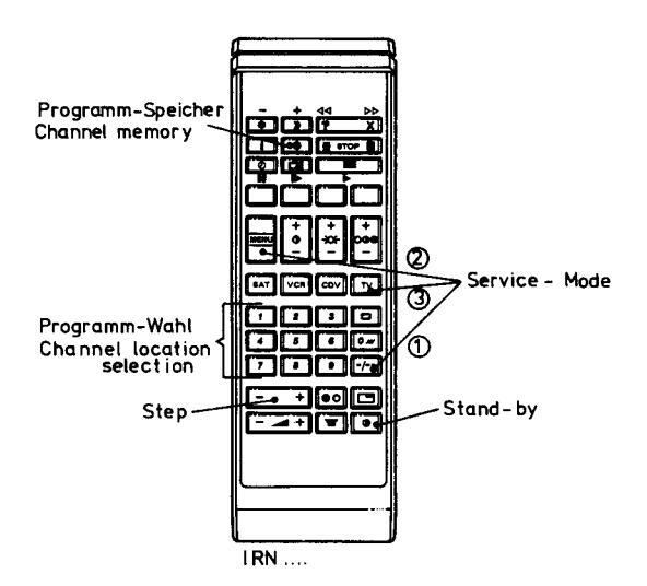
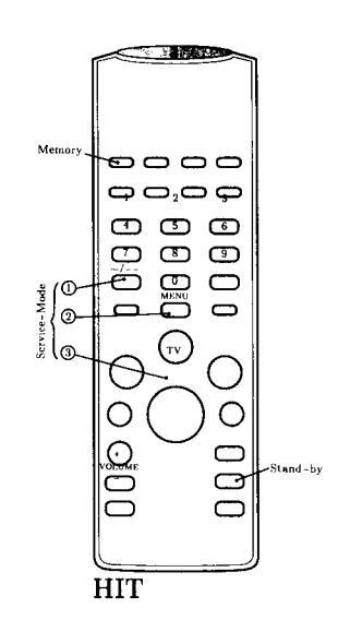
Tastenbelegung der IR-Sender bei Service-Betrieb. Infrared remote gun functions in Service mode. Occupation des touches de l'émetteur IR en mode de fonctionnement service. Occupazione dei tasti des trasmettitore a raggi infrarossi in funzionamento di servizio. Funciones y modo de servicio del control remoto de infrarojos.
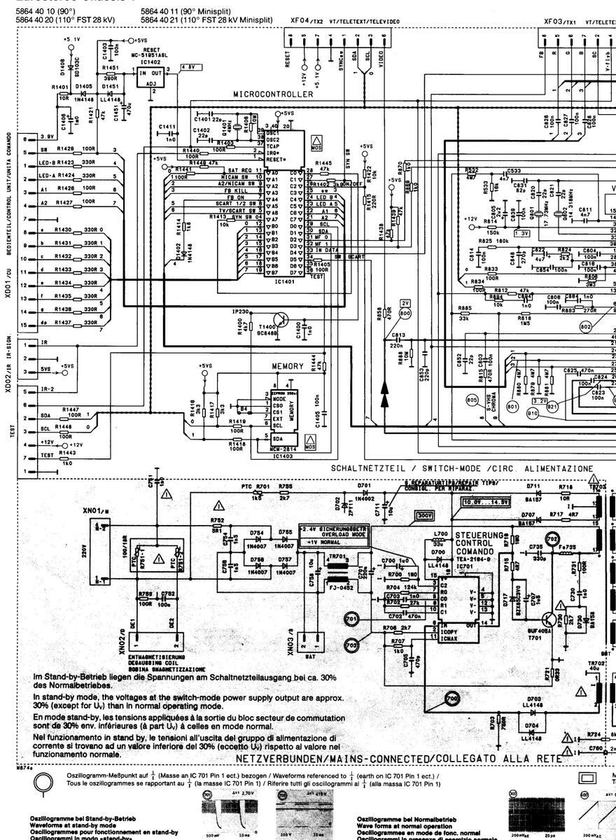
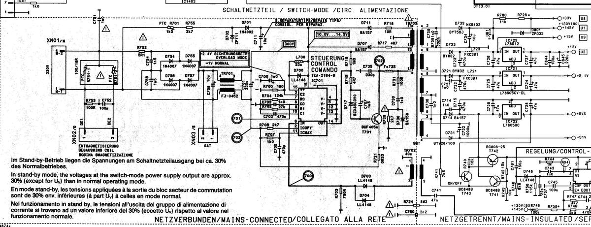
Schaltnetzteil / Switch mode
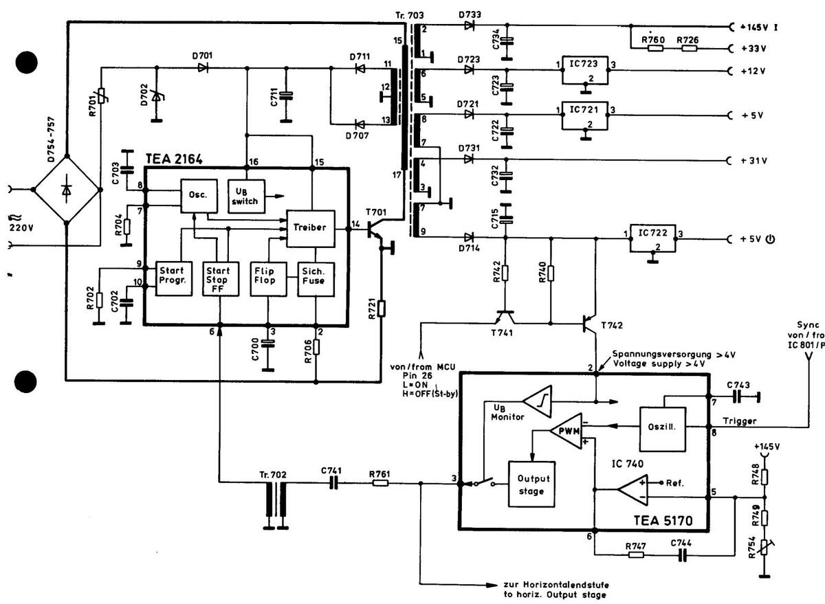
Cut off-Regelung

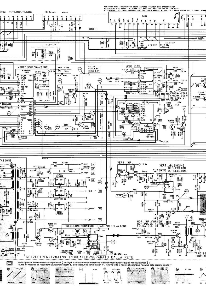
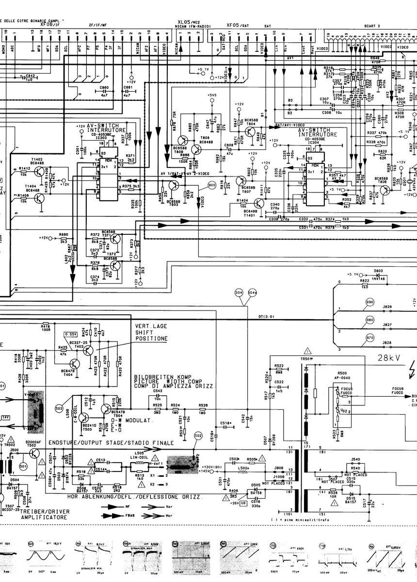
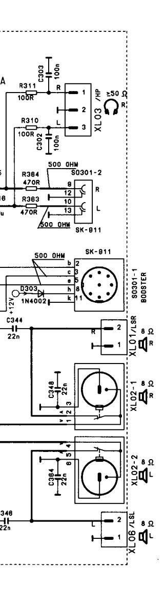
VIDEO
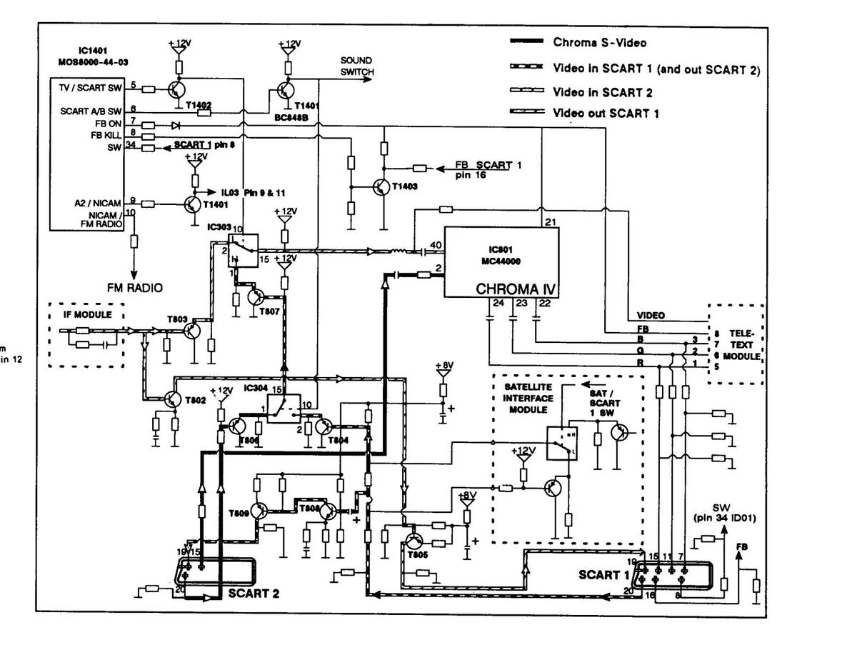
AUDIO
Instructions for repair work
N.B.: (cc. switch-mode) Please use only original component 3422 06 37 for C 711 . If standard size electrolyt capacitor C 711 is used, parallel 0,47 µF MTK must be installed additionally .
- The power pack can be oscillated when switching stage T 701 (base open) has been disconnected. The square-wave signals at pin 14 IC 701 (19–20 kHz) are interrupted for approx. 14 ms. The reason for this is that IC 740 (TEA 5170) is not synchronized at pin 6.
- In order to render IC 740 (TEA 5170) functional, this IC must be supplied with an external voltage at pin 2 (12 V). N.B.! When the switching stage has been disconnected, discharge electrolytic capacitor C 701 before reconnecting (soldering) it 2. With the horizontal output stage disconnected (e.g. connection 11 at Tr. 501 open) and a substitute load at the cathode of D 733 (100 W bulb), the power pack must supply approx. 100% of the setpoint voltages for 2 sec.
- 3. For servicing the set under operating conditions when the electronic fuse has activated, can be connected across C 700. If the electronic fuse cuts out due to a momentary overload, the appliance can be re-started by switching the mains switch off and then on again.
- Make sure there is hum-free d.c. voltage available. For example: the ripple voltage of U1 is approx. 4 V and should, due to capacitance loss of C 734, not increase much more. The ripple voltages of the other d.c. voltages should be less than 1 V. The ripple voltages of U2, U3, U5 are in the mV range.
D 1. Fehlerquellenanzeige am Bedienteil im TV-Betrieb
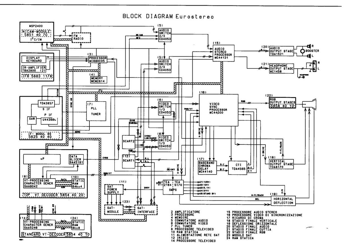
Nach dem Einschalten des Gerätes kommuniziert der Microprozessor IC 1401 über einen I2C-Bus, während der Vert. Rücklaufzeit, mit den verschiedenen integrierten Schaltkreisen bzw. Modulen.
Dabei überprüft der Microprozessor (Sender) zunächst ob überhaupt eine Datenübertragung möglich ist. Sollte einer dieser integrierten Schaltkreise ausfallen oder in seiner Peripherie ein Fehler vorliegen, so blinken eine oder mehrere LED'S laut folgender Tabelle auf.
(B) 1. Error-source display at the control panel in TV operation
After the set has been switched on, microprocessor IC 1401 communicates with the various integrated circuits and/or modules via an I2C bus during vertical retrace time.
While doing so, the microprocessor (transmitter) first of all checks whether it is at all possible to transmit data. Should one of these integrated circuits fail, or should an error occur in its peripherals, one or several LED's will start to flash , as detailed in the table below.
(F) 1. Indication des sources d'erreur sur l'organe de commande en mode TV
Après avoir mis l'appareil en marche, le microprocesseur IC 1401 communique au cours du temps de retour vert. via un bus l2C avec les différents circuits intégrés resp. modules.
Ce faisant, le microprocesseur (émetteur) contrôle d'abord si un transfert de données est réalisable. Au cas où l'un de ces circuits intégrés tomberait en panne ou au cas où un dérangement existerait dans sa périphérie, une ou plusieurs DEL du tableau suivant clignotent.
1. Indicazione della fonte di errore: display di comando nel funzionamento TV
Dopo aver acceso l'apparecchio il microprocessore IC 1401 comunica con i diversi circuiti di comando integrati e moduli tramite un bus I2C.
Il microprocessore (emittente) controlla dapprima se sia possibile una trasmissione di dati. Nel caso in cui uno di questi circuiti di comando integrati dovesse essere fuori uso oppure vi siano errori nella sua unità periferica, lampeggiano uno o più LED secondo le tabella riportata più in basso.
Fehlersuchtabelle
Trouble-shooting table Tableau de dépistage des erreurs Tabella di ricerca dell'errore
|
Fehler
Error Erreur Errore |
I. Ton LED
LED for sound I DEL son I LED I tono |
II. Ton LED
LED for sound II DEL son II LED II tono |
SAT-LED
SAT LED DEL SAT LED SAT |
SAT R-LED
SAT R LED DEL SAT R LED SAT R |
|---|---|---|---|---|
| Chroma IV | , | |||
|
Stereo-NF
Stereo AF Stéréo NF Stereo NF |
• | |||
|
PLL-tuner
PLL-tuner Tuner PLL Sintonizzatore PLL |
||||
| VT | • | |||
| Nicam* | ||||
|
kein vert. Impuls
no vertical flyback pas d'impulsion vert. No ritorno verticale |
||||
|
I
2
C Bus
I 2 C bus I 2 C bus blocked CI 2 bus bloccato |
||||
| EEPROM | ||||
|
Radio* / Satellit*
Radio* / satellite* Radio* / Satellite* Radio* / Satellite* |
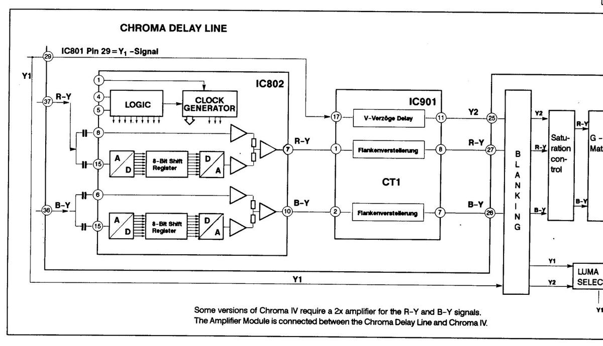
- Wird ein Fehler im Chroma IV IC (IC 801) oder in der Vert. Endstufe festgestellt, so schaltet das Gerät in den Stand-by-Betrieb und die entsprechenden LED's blinken. Gleiches gilt für einen zu hohen Strahlstrom.
- Bei einem EEPROM oder I2C-Bus-Fehler blinken die LED's und das Gerät bleibt im Stand-by-Betrieb (ohne Stand-by Betriebsanzeige "--")
- Ist da Satelliten-, Radio-, oder das VT-Modul nicht bestückt, so zeigt das Gerät einen fehlerfreien Betrieb an.
- If an error is detected in the chroma IV IC (IC 801) or in the vertical output stage, the set will switch to stand-by mode, and the corresponding LED's will start to flash. The same applies if there is an excessively high beam current.
- If there is an EEPROM or I2C bus error, the appropriate LED's will start to flash, and the set will remain in stand-by mode (without the standby- operating display "--").
- If the satellite, radio or VT module is not fitted, the set will display trouble-free operation.
- Si une erreur est détectée dans l'IC chroma IV (IC 801) ou dans l'étage final vert., l'appareil passe en mode stand-by et les DEL correspondantes clignotent. Il en est de même en présence d'un courant de faisceau trop élevé.
- Dans le cas d'une erreur dans l'EEPROM ou le bus l'C, les DEL clignotent et l'appareil reste en mode stand-by (sans indicateur de service stand-by «--»).
- Si les modules satellite, radio ou VT ne sont pas équipés, l'appareil indiquera un fonctionnement exempt d'erreurs.
- Se si determina un errore nel chroma IV (IC 801) oppure nello stadio di uscita verticale, l'apparecchio di porta in posizione di stand-by e lampeggiano i relativi LED. Lo stesso dicasi per una corrente catadica troppo elevista.
- una corrente catodica troppo elevata. In caso di errore in un'EEPROM oppure nel bus l2C, i LED lampeggiano e lo'apparecchio rimane in posizione di stand-by (senza indicazione di funzionamento in stand-by «--»).
- Se non è installato il modulo satellite, radio oppure quello VT, l'apparecchio indica un funzionamento privo di errori.
(GB) 2. Display on the control panel in service mode
LED for sound | = PAL recognition
- LED for sound II = SECAM recognition
- = Max. beam current, lower limit SATRIED = Max beam current upper limit
(F) 2. Indication sur l'organe de commande en mode de service
- DEL son I DEL son II = reconnaissance SECAM
- DEL SONT = reconnaissance SECAM = courant de faisceau max limite inférieure
- DELSATR = courant de faisceau max. limite supérieure
2. Indicazioni sul dispositivo dei comandi nel Service Mode
- = Riconoscimento PAL LED II Tono
-
Riconoscimento FAL LEDING
- Corrente catodica massima limite inferiore
- LED SAT R = Corrente catodica massima, limite interiore
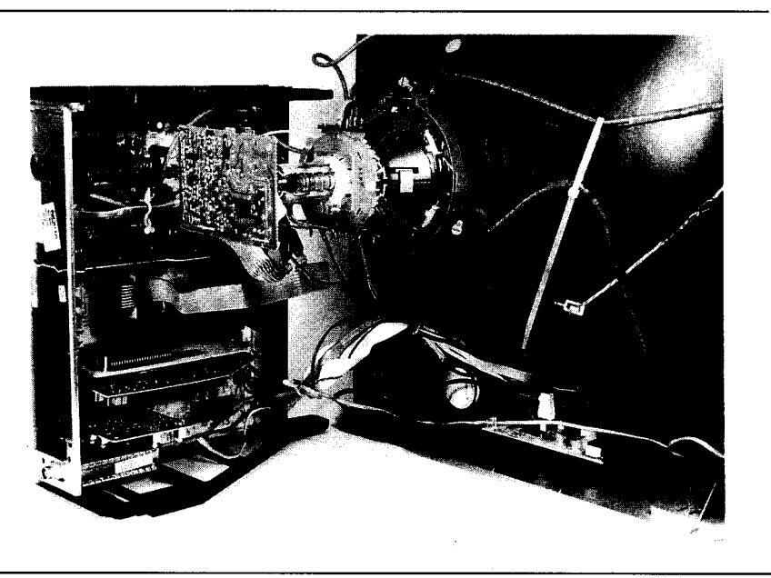
Service-Stellung des Chassis Service position of chassis Position de maintenance du châssis Voce relativa all'assistenza del telaio
D Kurzbedienungsanleitung Menügeführte Bedienungsschritte mit der Fernbedienung. Einstellungen erfolgen mit den Tasten Step + (-). Lautstärke, Farbstärke, Helligkeit und Kontrast können auch ohne Menü eingestellt werden.
| 1 x Rot-Taste | 1 x Grün-Taste | 1 x Gelb-Taste | 1 x Blau-Taste | |
|---|---|---|---|---|
| 1 x Menü-Taste | Stereo-Balance | Bässe | Höhen | Kopfhörerlautstärke |
| 2x Menü-Taste | Helligkeit | Farbstärke | Kontrast | Farbton (NTSC-Video) |
| 3x Menü-Taste | Stereo/Mono | Tonkanal I/II | Hypersonic | - |
| 4x Menü-Taste | Lautstärke |
– Ton aus
− Ton ein mit ₡ |
Memory |
Umschalten zu den nachfolgenden
Programmierfunktionen. |
|
4x Menü
1x Blau-Taste |
Programmwahlplatz wählen.
Mit "-/" und den Zifferntasten Pro- grammplatznr. eingeben und mit Step +() Sender suchen. Mit 0 und 1 oder 0 und 2 den Video- programmplatz wählen (EXT 1') |
Kanaltabelle A/B wählen, mit Step
+(-) oder Zifferntasten Kanäle anwählen, Für EXT 1' (1) RGB oder für EXT 2' (2) S-Video wählen, |
Bild- und Tonnorm einstellen. (PAL
und System 1) Taste ⊂ schaltet um zwischen Bild- und Tonsystem. |
Werte abspeichern (Memory). |
zum Löschen des Menüs vom Bildschirm die Taste 🗔 TV oder i drücken
GB Summarized instructions Menu-prompted operating steps using the remote control. To adjust, use buttons " Step + (-)". Volume, colour intensity, brightness and contrast coan also be adjusted directly, without using the menu.
| Press red button once | Press green button once | Press yellow button once | Press blue button once | |
| Press menu button once | Stereo balance | Basses | Trebles | Earphones volume |
| Press menu button twice | Brightness | Colour intensity | Contrast | Hue (NTSC video) |
| Press menu button three times | Stereo/mono | Audio channel I/II | Hypersonic | _ |
|
Press menu button four
times |
Volume |
|
Memory | Switching over to the subsequent programming functions. |
|
press menu button four
times press blue button once |
Select channel selection location.
Enter channel memory location number ber using "-/" and the numbered buttons, and search for stations with "Step +{-)". Use 0 and 1 or 0 and 2 to select the video channel memory location (EXT 1') |
Select Channel Table A/B. Select
channels unsing "Step +(-)" or the numbered buttons. Select RGB for EXT 1' (1), or S-VIDEO for EXT 2' (2). |
Adjusting video and audio standard
(PAL and System 1). Button S is used to switch over between video and audio system. |
Store values in memory. |
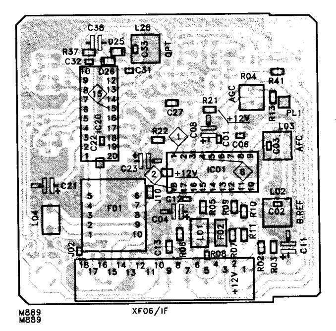
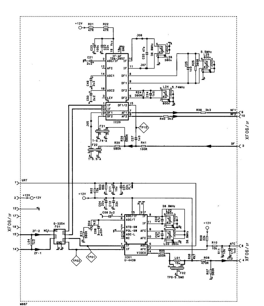
ZF-Modul IF module Module MF Modulo MF
5825 40 20 (Norm I)
Nach Austausch des Moduls sin keine Abgleicharbeiten
Replacing a defective module does not necessitate realignment.
Aucun ajustage n'est necessaire en cas remplacement du module.
Nel caso di sostituzione de moduli non è necessaria nessuna taratura.

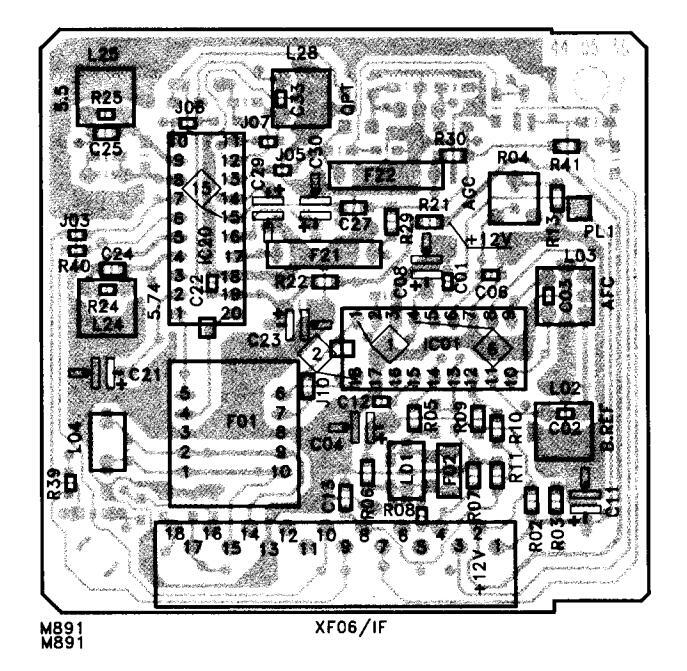
ZF-Modul IF module Module MF Modulo MF
5825 40 40 (Norm BG, Nicam)
Nach Austausch des Moduls sind keine Abgleicharbeiten erforderlich
Replacing a defective module does not necessitate realignment.
Aucun ajustage n'est necessair en cas remplacement du module.
Nei caso di sostituzione dei moduli non è necessaria nessuna taratura.


(103 --112
Ì
ZF-Ausgang symmetrisc IF-output symmetrica
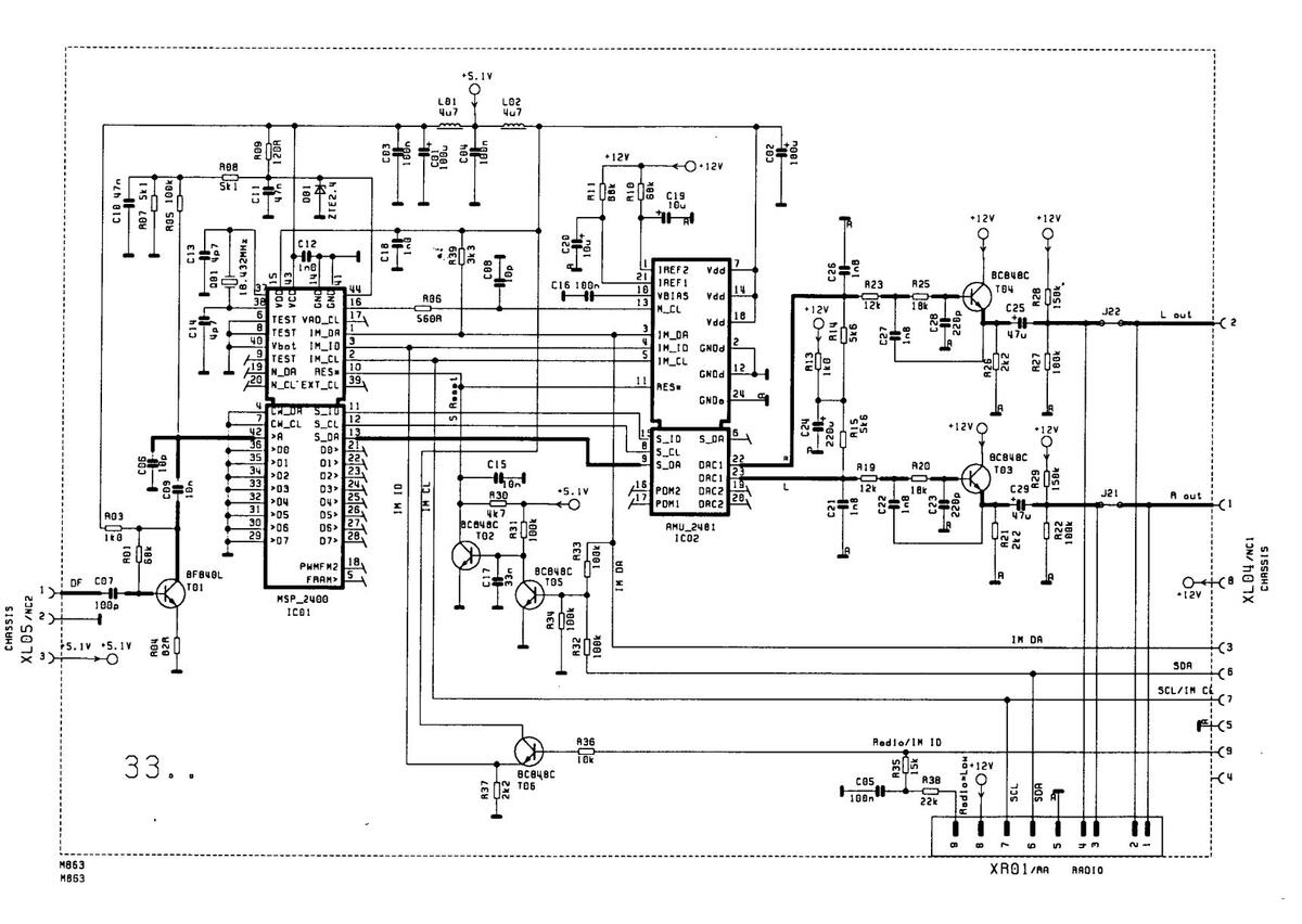
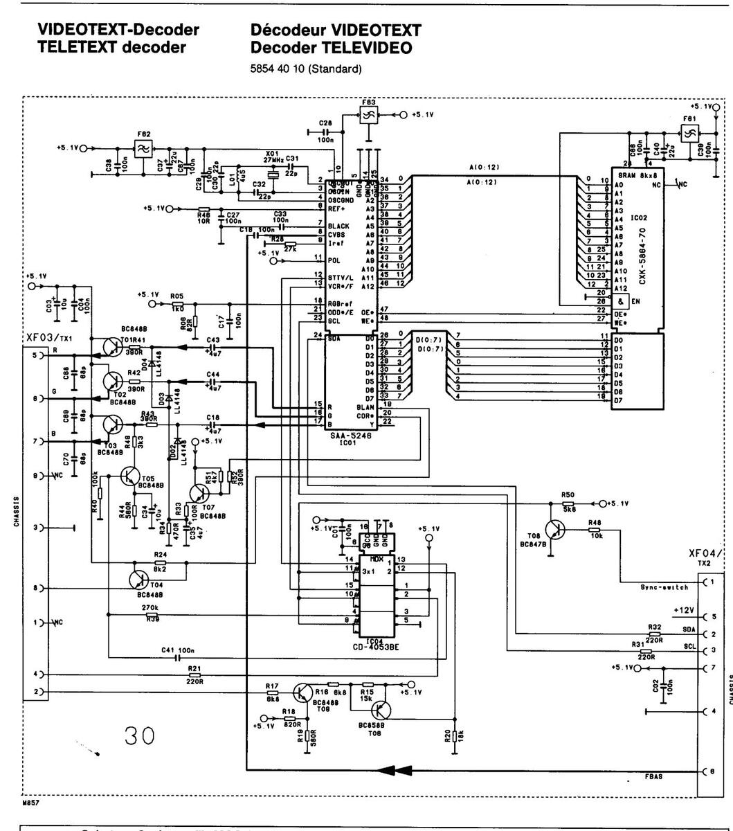
VIDEOTEXT-Decoder TELETEXT decoder Décodeur VIDEOTEXT Decoder TELEVIDEO
5854 40 20 (Euro-Top)
Bei Austausch des Moduls sind keine Abgleicharbeiten erforderlich.
Replacing a defective module does not necessitate realignment.
Aucun ajustage n'est necessaire en cas remplacement du module.
Nel caso di sostituzione del noduli non è necessaria nessuna taratura.
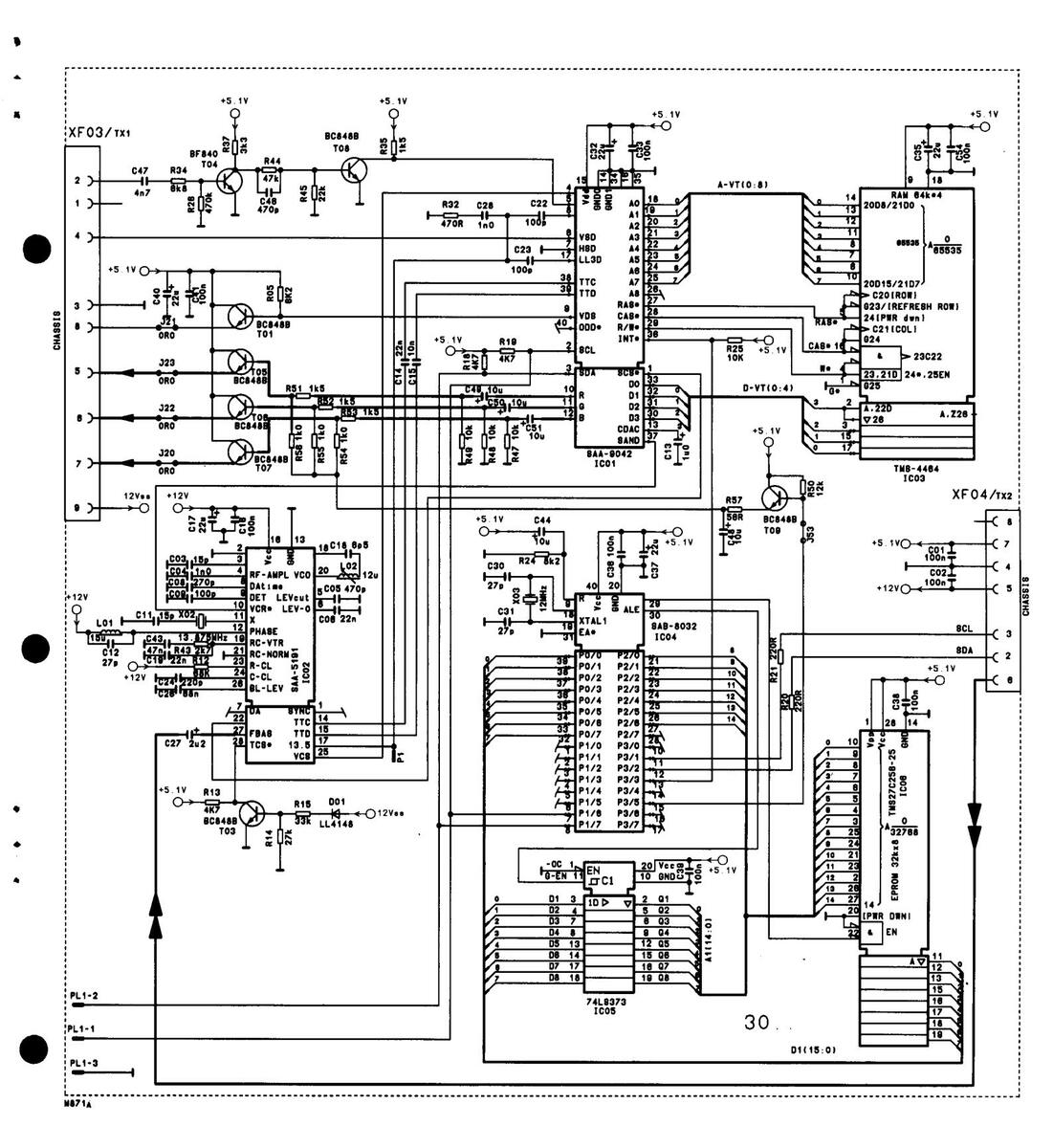

VIDEOTEXT-Decoder TELETEXT decoder Décodeur VIDEOTEXT Decoder TELEVIDEO
5854 40 20 (Euro-Top)
Schutzmaßnahmen für MOS-Bauelemente beachten! Pay attention to protective measures for MOS components! Respecter les mesures de protections pour les composants de MOS! Osservare le misure protettive per gli elementi costruttivi MOS!
Bei Nachbestellungen von Manualen, Gerätetyp und Geräte-Ident-Nummer angeben. When re-ordering manuals, please quote the model name and part number. En cas de commande supplémentaire de manuels veuillez indiquer le type et le numéro de l'appareil. Per riordinare i manuali, indicare il modello dell'apparecchio ed il numero categorico.
6611 76 08 (842) S
D 10


 Loading...