

SERVICE-INFORMATION

ITT IS A TRADE MARK OF ITT CORPORATION NEW YORK USED UNDER LICENSE
NOKIA 7142
ung! Bei Reparaturen gültige Sicherheitsvorsc genverordnung: Die in der Röntgenverordnung issigeregie unsaosisleistung ist bei diesem Gerät durch die Bildröhrentype und die maximal zulässige Hochspannung ihrleistet. Die Hochspannung darf maximal 27 kV betragen. Die Hochspannung liegt im zulässigen Bereich, wenn die Betriebsspannung der Horizontal-Ablenksturde bei nalem Strahistrom 122 V (90°) 148 V (110°) beträgt. Bei Reparaturen ist die Spannung zu überprüfen und gegebenerfalls mit O PO2 auf Sollwert einzustellen, rning1
malem Stranistrom 122 V (90°) 148 V (110°) beträgt. Bei Reparaturen ist die Spannung zu überprüfen und gegebenenfalls mit O P02 auf Sollwert einzustellen, hing! For repair works adhere to existing safety regulations. y regulations: The picture tube type and the maximum permissible high-voltage ensure that the X-ray intensity within the set remains far below the permissible value. The i-voltage must not exceed 27 kV. The high voltage is within the permissible limits when the operating voltage of the horizontal deflection stage equals 122 V (90°) 148 V (110°) at imum beam current. Following servicing, check and adjust this voltage to the nominal value with O P02.
minimum beam current. Following servicing, check and adjust this voltage to the nominal value with O P02. Attention! En cas de réparations, tenir compte des règles de sécurité en vigueur. Réglementation portant sur les rayons X: La puissance de dose locale fixée dans la réglementation relative aux rayons X est garantie dans le cas de cet appareil grâce au type de tube-image et à la haute tension maximale admissible. La haute tension ne doit pas dépasser un maximum de 27 kV. La haute tension se situe dans une zone admissible lorsque la tension de service de l'étage de convergence horizontale s'elève à 122 V (90°) 148 V (110°) pour un courant de faisceau minimal. En cas de réparations, la tension doit ête contrôlée et, le cas échéant, être ajustée sur la valeur de consigne au moyen de O P02. Attenzione! Per riparazione fare attenzione alle valevoii prescrizioni di sicurezza. Regolamento raggi X: La potenza prevista dall disciplina raggi X per questo genere di apparecchio viene garantita dal tipo di cinescopio e dalla tensione massima consentita. La tensione massima deve comportare 27 kV max. La tensione massima si trova nei limiti consentiti se la tensione di esercizio della fase terminale-orizzontale comporta a corrente minima catodica 122 V (90°) 148 V (110°). Controllare, in caso di riparazione, la tensione, e, all'occorrenza, mettere a punto, a valore nominale, mediante O P02.
|
Einstellung / Adjustment
Réglage / Taratura |
Pos. | einstellen auf / adjust to / Régler afin / regolare su |
Hinwelse, Vorbereitungen ect.
Notes / Remaruques / Avvisi |
|---|---|---|---|
|
UI
Betriebsspannung Operating voltage Tension de service Tens. d'esercizio |
O P02 |
122 V ± 0.5 V an / on / sur / su Diode (Kathode) O D 22 (90°)
148 V ± 0.5 V an / on / sur / su Diode (Kathode) O D 22 (110°) |
0 / -}O;- = min |
|
Hor. Ampl. (90°)
(110°) |
5 L06
5 P102 |
106% FuBK-Testbild / Test picture / mire / immagine di test | |
|
Hor. Bildlage / pict shift
Pos. hor. de l'image Pos. orizz. immagine |
5 P02 | ||
|
O-W Kissen/E-W cushion
Coussin E-O/Cuscin. EO |
5 P100 | 110° Chassis | |
|
Trapez / Trapezium
Trapèze / Trapezio |
5 P104 | 110° Chassis | |
| Vert. Ampl. | 6 P04 | Kreis / circle / cerchio |
= eingestellt sein
+ must be properly adjusted doit deja étre réglée deve essere regolata |
| Vert. Lin | 6 P02 | ||
|
Focus
(Hor. Trafo / Line transf. Trasform orizz.) |
5 L08 | optimale Schärfe / max. sharpness / netteté optimale / immagine ottimale |
= Testbild / Test picture
mire / immagine di test |
1 Uga
- Helligkeit auf mittleren Wert und Kontrast auf Minimum einstellen. Mit Oscilloscop (Tastkopf 100:1) den höchsten Schwarzwert an den Bildröhrenkathoden (R, G, B) ermitteln. Mit G-Einsteller (am Zeilentrafo 5 L08) den Wert dieser Kathode auf 130 V (90°-Chassis) 150 V (110°-Chassis), gemessen gegen
- Masse, einstellen
- Mit Hilfe des Fernbedienungsgebers können Sie im Service-Mode den Schwarzabgleich (Rot und Grün!), den Tunertyp (Telefunken oder Salcomp/Samsung!) und die Festwerte für Hotel-Geräte einstellen. Sie kommen in den Service-Mode, wenn Sie Taste "MENU" ("P"), Taste "-", Taste "+", Taste "-" und dann Taste "-"+"
- drücken. 2.2. Taste " MENU " (" P ") = weiterschalten von Abgleich zu Abgleich. 2.3. Taste " CZD " = Memory. 2.4. Taste " C " = Service-Mode verlassen.
- Schwarzabgleich (Uez muß eingestellt sein!). In Service-Mode gehen. (OSD-Anzeige "RCO..."). Im Rot- bzw. Grünabgleich mit "+ –" Tasten in den dunklen Partien auf farbneutrales Bild einstellen. Mit Taste "IMD" Werte abspeichern.
- Tun ontrolle (im Service-Mode)
- 4.1. .MENU" (.P")-Taste drücken (OSD-Anzeige .TUNER...")
- 4.2. Mit grüner Taste "S" = Salcomptuner/Samsungtuner (OSD = "TUNER S") oder "T" = Telefunkentuner (OSD = "TUNER T") einstellen. Mit Taste [20] jew. eingebauten Tuner ("S" oder "T") abspeichern. TV-Hotel (im Service-Mode). TV-Hotel (im Service-Mode). "MENU" ("P")-Taste drücken (OSD-Anzeige "HOTEL..."). Mit grüner Taste "NO HOTEL TV" einstellen. (OSD = "HOTEL NO") Mit Taste OSD abspeichern.
GB VG VG2 Adjust the brightness in the mittle position and contrast minimum. Point of scope on the high cathode. Adjust G2 (line transf.) on 90° Chassis 130 V and 150 V 110° Chassis between the black signal level video and the ground. In Service mode, you can use the remote control transmitter to set black level adjustment (red and areen), the tuner type In Service mode, you can use the remote control transmitter to set black level adjustment (red and green), the Telefunken or Salcomp/Samsung and Hotel sets. To go to service mode, press button "MENU" ("P"), button "-", button "+", button "-" and then button "-" +". button MENU" (P") = switching over from calibration to calibration. 2.2. button "MENU" ("P") = switching 2.3. button "IMI" = memory. 2.4. button □" = Exit service mode 2.4. hutton button "= Exit service mode. Black level adjustment (Eg2 must have been set). 3.1. In service-mode (OSD indicator - RCO ----") 3.1. In service-mode (USD indicator "HCO...). 3.2 Use the + -* button to adjust to a colour-neutral picture in the light areas in red and green. 3.2. Use the "+ - button to adju 3.3 With button [M]" = memory Tuner control (service mode) 4. Tuner control (service mode). 4.1. button "MENU" ("P") (OSD indicator "TUNER..."). 4.2. With button "green" adjust "S" = Salcomptuner/Samsungtuner (OSD = "TUNER S") or "T" = Telefunkentuner (OSD = "TUNER T") with button "CD" memory ("S" or "T"). TV-hotel (service mode) IV-notel (service mode). 5.1. button "MENU" ("P") (OSD indicator "HOTEL..."). 5.2. With button "green" adjust "NO HOTEL TV" (OSD = "HOTEL NO") 5.3. With button [MM]" = memory Taratura griglia scherma Luminosità sulla posizione mediana e contrasto sulla posizione min Luminosita suna posizione mediana e contrasto suna posizione min. Tramite l'oscilloscopio, determinare il valore del livello massimo del nero sui catodi del cinescopio (R. V. B) Con regolare 5 L08 (orizzontale transformer), registrare questo valore su 130 V (90° Chassis) 150 V (110° Chassis), misurato a Con L'ausilio del transmettitore a distanza potrete regolave i valori regolazione del nero (red e verde!), di tuner (Telefunken e Salcomp/Samsung!) e apparecchi Hotel in Service-Mode. Salcomp/Salmsung!) e apparecchi Hotel in Service-Mode. 2.1. E' possibile accedere al Service-Mode, premendo entro il tasto "MENU" ("P"), il tasto "—". il tasto "—". il tasto "—" e quindi il tasto " MENU " (" P ") = commutazione da compensazione a compensazione. Tasto " MENU " (" P ") = memorizzati. Tasto " D " = abbandonare il modo di servizio. Begolazione del nero (G2 = taratura di servizio) 3.1. E' possibile accedere al Sercice-Mode. (OSD = .RCO...*) 3.2. Nel rosso e nel verde, regolare le zone nero chiave con il tasto "+ --" ad immagine di colore neutro. 3.3. Con il Tasto .................................... Tuper controllare (Service-Mode) Tuner controllare (Service-Mode). premendo il tasto "MENU" ("P") (OSD-Anzeige "TUNER..."). Immagine il tasto "verde" "S" = Salcomptuner/Samsungtuner e "T" = Telefunkentuner. Con il Tasto [X2] memorizzati "S" e "T" (in apparecchi Telefunkentuner e Salcomptuner!).
- TV-Hotel (Service-Mode)
- TV-Hotel (Service-Mode). premendo il tasto "MENU" ("P") (OSD "HOTEL..."). Immagine il tasto verde "NO HOTEL TV" (OSD = "HOTEL NO"). con il tasto "IIII" = memorizzati.

Chroma PAL
Chroma PAL
Chroma PAL

Farbbalkentestbild. Oszilloscop an blaue Bildröhrenkathode. Zwei Zeilen übereinander schreiben Mit 7 P02 die Zeilen auf gleiche Amplitude einstellen.
(GB)
Apoly a bar pattern PAL RF plug. Connect a scope to the blue cathode. Adjust 7 P02 untel two concecutive lines are brought to converge

Segnale a barra colorata. Oscilloscopio a blu catodi del cinescopio. Scrivere due righe una sopra l'altra. Con regolare 7 P02 sullo stesso amplitude
Einsteller auf der Chassisplatte Location of adjuster on chassis board Regolatore schema su piastra «chassis»
Chassis Euromono
5864 21 00 (90° MN BG DK) 5864 21 10 (90° NN BG DK) 5864 21 20 (110° BG DK)
Schaltbildausschnitt Circuit diagram section Particolare dello schema elettrico

Erläuterungen zu den Schaltbildern / Circuit diagram legend Légendes des schémas / Spiegazioni dei simboli usati sullo schema
Messungen auf 1 (Masse) bezogen / Measurements referenced to earth (1) / Toutes les mesures se rannortent à la masse / Biferire tutte le misure alla massa
Messungen auf Schaltnetzteil-Minuspotential 🏐 bezogen / Measurements referenced to switch-moded power supply minus potential 🔘 / Toutes les mesures se rapportant au potentiel négatif du bioc-secteur de commutation 🗇 / Biferire tutte le misure al potenziale negativo della sezione di rete 🕥
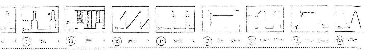
Oszillogramm-Meßpunkt auf 1 (Masse) bezogen / Waveforms referenced to earth (1) / Tous les oszillogrammes se rapportant à la masse / Riferire tutti gli oscillogrammi alla massa
Oszillogramm-Meßpunkt auf ⊚ bezogen / Waveforms referenced to ⊚ / Tous le oszillogrammes se rapportant au ∞ / Biferire tutti di oscillogrammi al ⊙
Testpunkt / Test point Boint test / Punto di controllo
Sicherheitsbauteil im Sinn der Sicherheitsbestimmung. Diese Teile dürfen nur durch Originalteile ersetzt werden. Safety components in accordance with existing regulations. These components must only be replaced by original comp Composant de sécurite en accordance avec les régulations existantes. Ces composants diovent être remplacés par de Componente amologiato in base alle norme di sicurgaza, questi nezzi devono essere sostituiti soltator con nezzi origi
Schutzmaßnahmen für MOS-Bauelemente beachten! Pay attention to protective measures for MOS components! Respecter les mesures de protections pour les components: Osservare le misure protettive per di elementi costruttivi MOSI
(GB)
∕∿
MOS
Audio power amplifier Central control unit Chroma processor Fast/West correction Filamente tube Filamente tube Frame amplifier Horizontal deflection Horizontal/Vertical time base Infrared receiver Line amplifier Mains switch Power supply Vertical deflection Video power amplifier Video power am
ത
NF-Endstufe Bedienteil-IC Chroma Prozessor Entmagnetisierung O-W Korrektur O-W Korrektur Bildröhrenheizung Ton-ZE Demodulator Vert Endetuto Hor. Ablenkung Hor./Vert. Impulsaufbereitung Infrarot-Empfänger Hor Endetute Netzschalter Schaltnetzteil-IC Vert. Ablenkund Video-Endstufe Video Prozessor
Stadio finale audi Unita comando IC Processore croma Robina smanetizzazione Bobina smagetiz Modulatore E/O Filamento cinescopio MF suono demodulatore Stadio finale verticale Deflessione orizzontale Separatore sinoro, oscillatore orizz, e. vert. Amplificatore IR Stadio finale orizzontale Interruttore Deflessione verticale Processore Video
Euro-AV-Buchse / SCART socket Prise Euro-AV / Presa di Peritelevisio
1 Audio B Ausgang / output / sortie / uscita
- 1 Audio B Ausgang / output / sorne / uscira 2 Audio B Eingang / input / entrée / entrata 3 Audio A Ausgang / output / sortie / uscita 4 Masse / earth / masse / massa
- 4 Masse / earth / masse / massa, blu 5 Blau, Masse / blue, earth / bleu, masse / massa, blu
- 5 Blau, Masse / blue, earth / bleu, masse / ... 6 Audio A Eingang / input / entrée / entrata 7 Blau / blue / bleu / blu
- 8 Schaitspannung / switching voltage / tension de commutation / commutazione di funzione
- 9 Grün, Masse / green, earth / vert, masse / massa verde 9 Grun, Masse / green, earth / vers, masse / local 10 Datenieitung 2 / data line 2 / ligne de données 2 / non collegato
- 11 Grün / green / vert / verde 12 Datenleitung 1 / data line 1 / ligne de données 1 / non collegato 12 Datenleitung 1 / data line 1 / ligne de données 1 / non collegato 12 Datenleitung 1 / data line 1 / ligne de données 1 / non 13 Rot, Masse / red, earth / rouge, masse / massa rosso 14 Masse / earth / masse / massa
- Masse / earth / masse / massa Rot / red / rouge / rosso (Chroma-Sign. / Chroma sign. / Sign. de chrominance / Segn. croma)
- 16 Austastsignal / blanking signal / signal de suppression / cancellazione
- 17 Video Masse / video earth / masse vidéo sortie / massa video 17 video Masse / video earth / masse video a 18 Austastsignal Masse / blanking signal earth / masse video entrée / massa cancellazione
- 19 Video Ausgang / output / sortie / uscita
- Video Ausgang / output / sortie / usoria Video Eingang / input / entrée / entrata (Luminanz-Sign. / Luminance sign. / Sign. de luminance / Segn. Luminanzi Abschirmung und/oder Masse Leitung / ../ nza)
- shielding and/or earth lead / blindage et/ou masse ligne
21 19 15 14 13 11 10 9 6
TUN IF-ASEL SOA SCL. Vtun PB_ 95 د 04 ،... GC.
E Ē s
м
| Chassis Euromono (90°) MN | BG | 5854 20 00 | |
| Chassis Euromono (90°) NN | BG | 5004 20 00 | |
| Chassis Euromono (90°) MN | 1 | 5864 23 00 | |
| Chassis Euromono (90°) NN | 1 | 5864 23 10 | |
| Chassis Euromono (90°) MN E | BG DK | 5004 23 10 | |
| Chassis Euromono (90°) MN E | IG DK | 5004 21 00 | |
| Chargie Euromono (110°) BG | 5864 21 10 | ||
| Chassis Euromono (110°) BG | 5864 21 20 | ||
| Chassis Euromotic (110°) EG | 5864 20 20 | ||
| Chassis Euromono (110-) 1 | 5864 23 20 | ||
| 0 IC 02 | TDA 4601 | 3765 13 66 | |
| 0 IC 04 | CNY 17 | 3657 12 51 | |
| 0 IC 06 | LM 317 T | 3768 18 15 | |
| 0 IC 08 | L 7805 C VP | 3768 18 04 | |
| 1 10 02 | TDA 1013 B | 3763 13 22 | |
| 310 02 | 1DA 4453 F | 3/61 16 45 | |
| 3 10 04 | 3761 13 30 | ||
| 410.02 | HCE 4053 MO 13 TB | MOS | 3773 53 75 |
| 4 10 04 | TEA 5040 | WICC | 3766 11 88 |
| 5 10 02 | TDA 8185 | 3763 12 65 | |
| 6 IC 02 | TDA 8170 | 3763 12 72 | |
| 7 IC 02 | TEA 5640 F | 3766 11 81 | |
| 7 IC 04 | HCF 4060 MO 13 TR | MOS | 3771 52 03 |
| 13 IC 02 | ST 24 C 02 A | 3776 50 50 | |
| 13 IC 04 | TVP 02066 OCA 1 | MOS | 3779 12 20 |
| 0 R 02 | 8,2 MΩ 0,54 W | ▲ 3156 09 70 | |
| 1 R 20 | 0,27Ω 0,3W | ▲ 3154 73 95 | |
| 3 R 232, 4 R 14 | 4,7 Ω 0,3 W | ▲ 3153 52 02 | |
| 5 R 44 (90°) | 4.7 Ω 0,33 W | ▲ 3154 09 89 | |
| 5 R 44 (110°) | 3,9Ω 0,5W | ▲ 3154 09 90 | |
| 5 H 56 | 4,712 0,125 W | ▲ 31547396 | |
| 0 C 02 | 0,22 μF 250 V | ▲ 3324 09 32 | |
| 0 C 10 | 2,2 nF 400 V | ▲ 3261 09 23 | |
| 5 C 42 (90°) | 0,39 μF 250 V | ▲ 3324 10 34 | |
| 5 C 42 (110°) | 0,27 μF 250 V | ▲ 3324 08 28 | |
| 5 C 102 (110°) | 39 nF 400 V | A 3324 09 92 | |
| 0 L Q2 | ▲ 4557 04 17 | ||
| 0 L 08 | ▲ 4523 15 85 | ||
| 5 L 08 (90°) | ZTR 6 4797-00 | ▲ 45150510 | |
| 5 L 08 (110°) | ZIN 6 40404561 | ||
| 144 | W 4312 18 39 | ||
| Netzschalter / Mains switch | ▲ 4112 22 20 | ||
| Commutateur principal / Interr | uttore principale | ||
| , | |||
| IFB/EM | |||
|---|---|---|---|
|
IC 1201
IC 1401 |
IRT 1250
TBA 2800 |
MOS
MOS |
3779 25 75
3763 08 13 |
|
Bildröhrenanschluß
C.R.T. base board Platine de connexio |
platte |
5858 20 1
5858 20 1 5858 20 2 |
|---|---|---|
| Plastra di allaccian | iento del cinescopio | 5858 20 2 |
| Plastra di allaccian | TEA 5101 A |
5858 20 2
3766 11 9 |
|
Plastra di allaccian
IC 1002 R 1020 |
τΕΑ 5101 Α
4.7 kΩ 0.3 W |
5858 20 2
3766 11 9 ▲ 3153 52 0 |
Ň

Oszillogramm-Meßpunkt auf ⊚ bezogen / Waveforms referenced to ⊚ / Tous le oszillogrammes se rapportant au ⊚ / Riferire tutti gli oscillogrammi al ⊚

IECTED
⚠
ons. These components must only be ons existantes. Ces composants diov
MAINS-ISOL
Δ


) 57 100

Achtung! Die Oszilloscopmasse muß in der Nähe der zu messenden Baugruppe angeschlossen werden.
N.B.! The oscilloscope frame must be connected near the module being measured.
Attention! La masse de l'oscilloscope doit être raccordée à
La massa dell'oscilloscopio deve essere collegata vicino al componente da misurare

Änderungen vorbehalten – Modifications reserved – Con riserva di modifiche – Modifications réservées


 Loading...