

Page 1

PAMS Technical Documentation
NSE–5 Series Transceivers
Service Software
Instructions
Issue 1 07/99
Page 2

NSE–5
PAMS
Service Software Instructions
Technical Documentation
CONTENTS
Service Software 5. . . . . . . . . . . . . . . . . . . . . . . . . . . . . . . . . . . . . . . . . . . . . . . . .
Hardware requirements for Windows 3.1x 5. . . . . . . . . . . . . . . . . . . . . . . .
Hardware requirements for Windows 95 5. . . . . . . . . . . . . . . . . . . . . . . . . .
Software Environment of the Support Modules 5. . . . . . . . . . . . . . . . . . . .
Required Servicing Equipment 6. . . . . . . . . . . . . . . . . . . . . . . . . . . . . . . . . .
Test and tuning with covers off 6. . . . . . . . . . . . . . . . . . . . . . . . . . . . . . .
Warranty transfer (phone to phone) 6. . . . . . . . . . . . . . . . . . . . . . . . . . .
Audio test equipment (optional) 6. . . . . . . . . . . . . . . . . . . . . . . . . . . . . .
RF test and tuning equipment 7. . . . . . . . . . . . . . . . . . . . . . . . . . . . . . . .
Extra equipment (for added accuracy on RF tuning): 7. . . . . . . . . . . .
Energy Management Calibration 7. . . . . . . . . . . . . . . . . . . . . . . . . . . . .
Infrared test equipment 7. . . . . . . . . . . . . . . . . . . . . . . . . . . . . . . . . . . . .
Flash programming equipment 7. . . . . . . . . . . . . . . . . . . . . . . . . . . . . . .
Equipment Setup 8. . . . . . . . . . . . . . . . . . . . . . . . . . . . . . . . . . . . . . . . . . . . . .
Installation 8. . . . . . . . . . . . . . . . . . . . . . . . . . . . . . . . . . . . . . . . . . . . . . . . . . .
Mechanical Connections 8. . . . . . . . . . . . . . . . . . . . . . . . . . . . . . . . . . . .
Installing the Software on PC Hard Disk 9. . . . . . . . . . . . . . . . . . . . . . .
First time installation of WinTesla: 9. . . . . . . . . . . . . . . . . . . . . . . . . . . .
Installation of NSE–5 support modules (WinTesla already installed): 10.
Equipment Setup for Tuning a Phone without Removing Covers 11. . . . .
Flash Concept for NSE–5 12. . . . . . . . . . . . . . . . . . . . . . . . . . . . . . . . . . . . . .
Tuning With Covers Off – Using Test–frame JBS–19 13. . . . . . . . . . . . . . .
Common Properties of the User Interface 16. . . . . . . . . . . . . . . . . . . . . . . . . . .
Login Dialog 16. . . . . . . . . . . . . . . . . . . . . . . . . . . . . . . . . . . . . . . . . . . . . . . . . .
Main Window 17. . . . . . . . . . . . . . . . . . . . . . . . . . . . . . . . . . . . . . . . . . . . . . . . .
Menu 19. . . . . . . . . . . . . . . . . . . . . . . . . . . . . . . . . . . . . . . . . . . . . . . . . . . . . . . .
Product 19. . . . . . . . . . . . . . . . . . . . . . . . . . . . . . . . . . . . . . . . . . . . . . . . . . .
Configure 20. . . . . . . . . . . . . . . . . . . . . . . . . . . . . . . . . . . . . . . . . . . . . . . . .
Tuning 20. . . . . . . . . . . . . . . . . . . . . . . . . . . . . . . . . . . . . . . . . . . . . . . . . . . .
Testing 20. . . . . . . . . . . . . . . . . . . . . . . . . . . . . . . . . . . . . . . . . . . . . . . . . . . .
Page 2
Software 21. . . . . . . . . . . . . . . . . . . . . . . . . . . . . . . . . . . . . . . . . . . . . . . . . .
Dealer 21. . . . . . . . . . . . . . . . . . . . . . . . . . . . . . . . . . . . . . . . . . . . . . . . . . . .
View 21. . . . . . . . . . . . . . . . . . . . . . . . . . . . . . . . . . . . . . . . . . . . . . . . . . . . . .
Help 22. . . . . . . . . . . . . . . . . . . . . . . . . . . . . . . . . . . . . . . . . . . . . . . . . . . . . .
Mouse Cursors 22. . . . . . . . . . . . . . . . . . . . . . . . . . . . . . . . . . . . . . . . . . . . . . .
Reserved Keys 23. . . . . . . . . . . . . . . . . . . . . . . . . . . . . . . . . . . . . . . . . . . . . . .
Short Cut Function Keys 23. . . . . . . . . . . . . . . . . . . . . . . . . . . . . . . . . . . .
Issue 1 07/99
Page 3

PAMS
NSE–5
Technical Documentation
Alt Hot Keys 23. . . . . . . . . . . . . . . . . . . . . . . . . . . . . . . . . . . . . . . . . . . . . . .
Ctrl Hot Keys 23. . . . . . . . . . . . . . . . . . . . . . . . . . . . . . . . . . . . . . . . . . . . . .
Shift Hot Keys 23. . . . . . . . . . . . . . . . . . . . . . . . . . . . . . . . . . . . . . . . . . . . .
Key Strokes 24. . . . . . . . . . . . . . . . . . . . . . . . . . . . . . . . . . . . . . . . . . . . . . .
Help Functions 25. . . . . . . . . . . . . . . . . . . . . . . . . . . . . . . . . . . . . . . . . . . . . . . .
Dialog boxes 26. . . . . . . . . . . . . . . . . . . . . . . . . . . . . . . . . . . . . . . . . . . . . . . . .
Common Dialog boxes 26. . . . . . . . . . . . . . . . . . . . . . . . . . . . . . . . . . . . . .
Custom Dialog boxes 28. . . . . . . . . . . . . . . . . . . . . . . . . . . . . . . . . . . . . . .
Buttons 28. . . . . . . . . . . . . . . . . . . . . . . . . . . . . . . . . . . . . . . . . . . . . . . . . . . . . .
Reporting Status 29. . . . . . . . . . . . . . . . . . . . . . . . . . . . . . . . . . . . . . . . . . . . . .
NSE–5 Features 30. . . . . . . . . . . . . . . . . . . . . . . . . . . . . . . . . . . . . . . . . . . . . . . . .
Product 30. . . . . . . . . . . . . . . . . . . . . . . . . . . . . . . . . . . . . . . . . . . . . . . . . . . . . .
New command 30. . . . . . . . . . . . . . . . . . . . . . . . . . . . . . . . . . . . . . . . . . . . .
Open... command 30. . . . . . . . . . . . . . . . . . . . . . . . . . . . . . . . . . . . . . . . . .
Service Software Instructions
Initialise... command 30. . . . . . . . . . . . . . . . . . . . . . . . . . . . . . . . . . . . . . . .
Normal Mode 30. . . . . . . . . . . . . . . . . . . . . . . . . . . . . . . . . . . . . . . . . . . . . .
Local Mode 31. . . . . . . . . . . . . . . . . . . . . . . . . . . . . . . . . . . . . . . . . . . . . . . .
Band command 32. . . . . . . . . . . . . . . . . . . . . . . . . . . . . . . . . . . . . . . . . . . .
GSM 32. . . . . . . . . . . . . . . . . . . . . . . . . . . . . . . . . . . . . . . . . . . . . . . . . . . . .
PCN 32. . . . . . . . . . . . . . . . . . . . . . . . . . . . . . . . . . . . . . . . . . . . . . . . . . . . . .
Faultlog command 32. . . . . . . . . . . . . . . . . . . . . . . . . . . . . . . . . . . . . . . . .
Activate Faultlog 32. . . . . . . . . . . . . . . . . . . . . . . . . . . . . . . . . . . . . . . . . . .
Edit Faultlog 32. . . . . . . . . . . . . . . . . . . . . . . . . . . . . . . . . . . . . . . . . . . . . . .
FastNAM command 33. . . . . . . . . . . . . . . . . . . . . . . . . . . . . . . . . . . . . . . .
Exit command 33. . . . . . . . . . . . . . . . . . . . . . . . . . . . . . . . . . . . . . . . . . . . .
Tuning 33. . . . . . . . . . . . . . . . . . . . . . . . . . . . . . . . . . . . . . . . . . . . . . . . . . . . . . .
General 33. . . . . . . . . . . . . . . . . . . . . . . . . . . . . . . . . . . . . . . . . . . . . . . . . . .
RX Calibration... command 33. . . . . . . . . . . . . . . . . . . . . . . . . . . . . . . . . .
Tx Power... command 39. . . . . . . . . . . . . . . . . . . . . . . . . . . . . . . . . . . . . . .
Tx I/Q... command 43. . . . . . . . . . . . . . . . . . . . . . . . . . . . . . . . . . . . . . . . .
Energy Management Calibration... command 47. . . . . . . . . . . . . . . . . .
Display Contrast Adjustment... command 51. . . . . . . . . . . . . . . . . . . . . .
Testing 53. . . . . . . . . . . . . . . . . . . . . . . . . . . . . . . . . . . . . . . . . . . . . . . . . . . . . . .
RF Controls... command 53. . . . . . . . . . . . . . . . . . . . . . . . . . . . . . . . . . . .
RSSI Reading... command 57. . . . . . . . . . . . . . . . . . . . . . . . . . . . . . . . . .
Self Tests... command 58. . . . . . . . . . . . . . . . . . . . . . . . . . . . . . . . . . . . . .
Supported Self Tests 60. . . . . . . . . . . . . . . . . . . . . . . . . . . . . . . . . . . . . . .
ADC Readings... command 61. . . . . . . . . . . . . . . . . . . . . . . . . . . . . . . . . .
Issue 1 07/99
Page 3
Page 4

NSE–5
PAMS
Service Software Instructions
Audio... command 62. . . . . . . . . . . . . . . . . . . . . . . . . . . . . . . . . . . . . . . . . .
Vibrator......command 64. . . . . . . . . . . . . . . . . . . . . . . . . . . . . . . . . . . . . . .
User Interface... command 65. . . . . . . . . . . . . . . . . . . . . . . . . . . . . . . . . .
Call Simulation... command 66. . . . . . . . . . . . . . . . . . . . . . . . . . . . . . . . . .
Noise Sensitivity... command 67. . . . . . . . . . . . . . . . . . . . . . . . . . . . . . . .
IR Test... command 69. . . . . . . . . . . . . . . . . . . . . . . . . . . . . . . . . . . . . . . . .
Software 70. . . . . . . . . . . . . . . . . . . . . . . . . . . . . . . . . . . . . . . . . . . . . . . . . . . . .
Product Profile... command 70. . . . . . . . . . . . . . . . . . . . . . . . . . . . . . . . . .
Start Up Self–tests... command 71. . . . . . . . . . . . . . . . . . . . . . . . . . . . . .
Set Factory Values... command 72. . . . . . . . . . . . . . . . . . . . . . . . . . . . . .
Phone Identity... command 73. . . . . . . . . . . . . . . . . . . . . . . . . . . . . . . . . .
Warranty State... command 75. . . . . . . . . . . . . . . . . . . . . . . . . . . . . . . . . .
Production Data Edit... command 76. . . . . . . . . . . . . . . . . . . . . . . . . . . . .
Flash Phone... command 78. . . . . . . . . . . . . . . . . . . . . . . . . . . . . . . . . . . .
Technical Documentation
Dealer 81. . . . . . . . . . . . . . . . . . . . . . . . . . . . . . . . . . . . . . . . . . . . . . . . . . . . . . .
User Settings... command 81. . . . . . . . . . . . . . . . . . . . . . . . . . . . . . . . . . .
Short Code Memory... command 82. . . . . . . . . . . . . . . . . . . . . . . . . . . . .
SCM & User Settings... command 84. . . . . . . . . . . . . . . . . . . . . . . . . . . .
Restore User Defaults... command 85. . . . . . . . . . . . . . . . . . . . . . . . . . .
Set UI/DEV Default Values... command 87. . . . . . . . . . . . . . . . . . . . . . .
Flash PPM......command 88. . . . . . . . . . . . . . . . . . . . . . . . . . . . . . . . . . . .
Operator Settings.......command 88. . . . . . . . . . . . . . . . . . . . . . . . . . . . .
IWR Swap Command 89. . . . . . . . . . . . . . . . . . . . . . . . . . . . . . . . . . . . . . .
View 90. . . . . . . . . . . . . . . . . . . . . . . . . . . . . . . . . . . . . . . . . . . . . . . . . . . . . . . . .
Quick/RF Info... command 90. . . . . . . . . . . . . . . . . . . . . . . . . . . . . . . . . . .
Phone Identity... command 92. . . . . . . . . . . . . . . . . . . . . . . . . . . . . . . . . .
Appendix 1, Vocabulary 93. . . . . . . . . . . . . . . . . . . . . . . . . . . . . . . . . . . . . . . . . . .
Page 4
Issue 1 07/99
Page 5

PAMS
NSE–5
Technical Documentation
Service Software
To run the After Sales SW, a parallel port software protection device
(PKD–1) has to be connected. TDF–4 box must connected to PC for
flashing purposes. The user can use PC–locals functions in modules for
testing NSE–5 mobile stations (MS).The test functions send test
messages from PC to MS and receive results and show them in the PC
display. The messages can be sent via M2BUS or FBUS.
Note1: if this software is to be run on laptops, the power saving feature MUST be
switched off. if this is not switched off you need to re–establish connection to the phone
after power saving has been active.
Hardware requirements for W indows 3.1x
The recommended minimum hardware standard to run Service Software
is any computer which is 386 33 MHz or greater with at least 4 MB of
memory and VGA type display (640 x 480). This assumes that only the
WinTesla with After Sales Support Modules is active, i.e. other Windows
packages are not running in the background.
Service Software Instructions
Hardware requirements for W indows 95
The recommended minimum hardware standard to run Service Software
is any computer which has Pentium processor, memory 8 MB and meets
HW requirements recommended by Microsoft.
Software Environment of the Support Modules
The Service Software user interface is intended for the following
environments: Microsoft Windows 3.1x and Windows 95 environment
running in enhanced mode as well as Microsoft NT. Detailed information
about Windows and application usage can be found from the Microsoft
Windows Version 3.1 Users Guide chapter one (Windows Basics) and
chapter two (Application Basics).
As an ordinary Windows application, the main idea in the user interface is
that selections are made with menus, push buttons and shortcut keys.
Selections can be done by using keyboard and/or mouse. There is always
a status bar displayed at the bottom of the main window which contains
information about current actions.
Issue 1 07/99
Page 5
Page 6

NSE–5
PAMS
Service Software Instructions
Required Servicing Equipment
- Computer: At least IBM 80386 or compatible with one unused serial
port (COM1 or COM2)*), one parallel port (LPT1), at least 20Meg of
free hard disk, 3.5” floppy disk and 4 Meg of RAM.
- Operating System:Win 3.1 or later
- Display: minimum monochrome graphic display with 640x480 resolu-
tion
- Service software version for 3.5” disk (product code: 0774046)
- Service software for NSE–5 version for 3.5” disk (product code:
0774117)
- One of the following protection keys:–
- Software protection key PKD–1 (product code: 0750018)
–Software protection key PKD–1CS (product code: 075Y002 )
–Software protection key PKD–1D (product code: 0750053)
–Software protection key PKD–1NS (product code: 075Y001 )
Technical Documentation
- RS 232 Serial Cable DSUB–9 female AX5–4 (product code: 0730090 )
- Service MBUS Cable DAU–9P (product code: 0730109)
- Service MBUS Cable DAU–9S (product code: 0730108)
- Service cable SCH–5 (product code: 0730098)
- Modular T–adapter (product code: 4626134)
*) Note: A number of PC’s of an older generation use the Intel, National
Semiconductor, or United Microelectronics IC 8250 as the serial port UART. This is a
comparatively inefficient circuit for current purposes and does not necessarily support the
M2BUS adapter at 9600 baud. The newer UART’s NS16450 and NS16550AF of National
Semiconductor offer solutions for these problems.
Test and tuning with covers off
- –DC Cable PCS–1 (product code: 0730012)
Either:
- –Module Jig JBS–19 (product code: 0770098)
- –SIM–Card holder CAH–1 (product code: 0770112)
Or:
- –Light Module Jig JBT–1 (product code: 0770109)
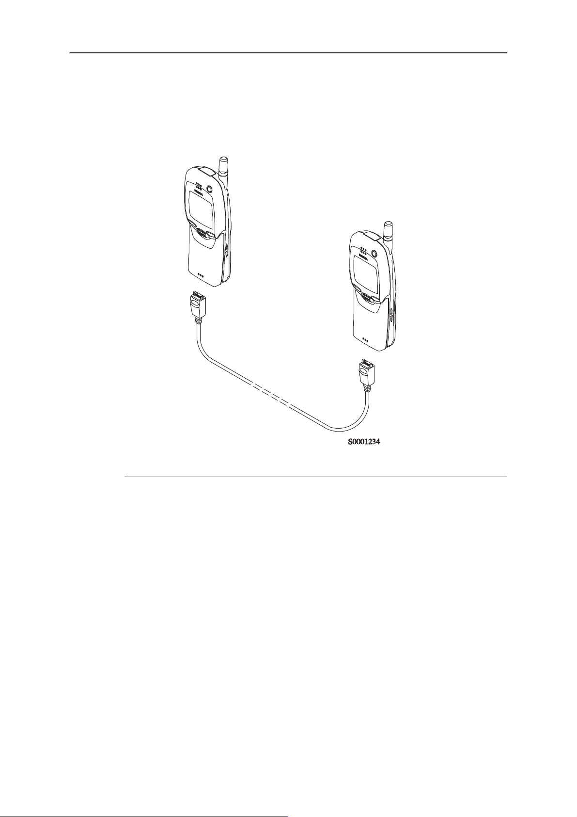
Warranty transfer (phone to phone)
- –Warranty cable SCH–6 (product code: 0730099)
Audio test equipment (optional)
- Audio cable ADS–1 (product code: 0730011)
- Service Audio Box JBA–4 (product code: 0770094)
- Function Generator (Sine–wave, 0–500mV, 1kHz)
- Oscilloscope
- Multimeter
- Headset HDC–9 (product code: 0694093)
Page 6
Issue 1 07/99
Page 7

PAMS
NSE–5
Technical Documentation
RF test and tuning equipment
- GSM/PCN Signal generator and tester (e.g. Rhode & Schwartz CMD
55)
- External Antenna Cable XRC–1B (product code: 0730128)
Extra equipment (for added accuracy on RF tuning):
- RF generator
- Pulse power meter
- GSM/PCN Spectrum analyser
- Attenuator and branching unit
Energy Management Calibration
- DC power supply that are capable of delivering 10.5 Volt DC
- Service battery BBD–3 (product code: 0775071)
- DC Charger calibration cable SCB–3 (product code: 0730114)
Service Software Instructions
Infrared test equipment
–Infrared test cable JLP–1 (product code: 0750079)
One of the following Travel chargers
–Travel charger ACH–6E (Euro) (product code: 0270381)
–Travel charger ACH–6U (USA/Japan) (product code: 0270382)
–Travel charger ACH–6X (UK) (product code: 0270380)
- Combox TDC–4 (product code: 0630119)
Flash programming equipment
Either:
- Point Of Sale flash adapter FLS–1 (product code: 075T000)
Or (the following can also be used instead of Combox TDC–4):
- Flash security box TDF–4 (product code: 0770106)
- Flash loading adapter FLA–5 (product code: 00800178)
- Flash Prommer sales package FPS–4S (product code: 0085095)
- Service battery BBD–3 (product code: 0775071)
–Travel charger ACH–6E (Euro) (product code: 0270381)
One of the following Travel chargers
–Travel charger ACH–6U (USA/Japan) (product code: 0270382)
- DC power cable PCC–1B (product code: 0770053)
Issue 1 07/99
–Travel charger ACH–6X (UK) (product code: 0270380)
Page 7
Page 8

NSE–5
PAMS
Service Software Instructions
Technical Documentation
Equipment Setup
Caution: Make sure that you have switched off the PC and the printer
before making connections!
Caution: Do not connect the PKD-1 key to the serial port. You may
damage your PKD-1!
Attach the protection key PKD-1 to parallel port one (25-pin female
D-connector) of the PC. When connecting the PKD-1 to the parallel port
be sure that you insert the PC end of the PKD-1 to the PC (male side). If
you use a printer on parallel port one, place the PKD-1 between the PC
and your printer cable.
Next connect the M2BUS service cable, DAU-9P, to the serial port
(RS-232) of the computer. Attach one end of the service cable to the PC
serial port and the other end to the service box, JBA-4. For servicing the
phone with the covers in place the service box should always be used.
When the phone covers are removed the jigs should be used.
For audio measurements connect the audio cable, ADS-1, as follows:
- EAR line to AF INPUT of test equipment
- MIC line to MOD GEN OUTPUT of test equipment
Installation
Mechanical Connections
The software controls the phone via a separate adapter connected to the
serial port of the PC, and to the telephone’s M2BUS (DAU–9P).
Attach the dongle PKD–1 to the parallel port 1 (25–pin female
D–connector) of the PC. When connecting PKD–1 to the parallel port, be
sure that you insert the computer side of the PKD–1 to the PC (male side).
If you use a printer on parallel port 1, install the PKD–1 between the PC
and your printer cable.
The PKD–1 should not affect devices working with it. If some errors occur
(errors in printing are possible) please try printing without the PKD–1. If
printing is OK without the PKD–1 please contact your dealer. We will offer
you a new PKD–1 in exchange for your old one.
Page 8
Issue 1 07/99
Page 9

PAMS
NSE–5
Technical Documentation
Installing the Software on PC Hard Disk
The program is delivered on a diskette and is copy protected with a
dongle PKD–1. It must be present in parallel port when using Service
software.
The program must be installed on the hard disk before use.
Keep the original diskette safe to enable upgrading of the program !
If you plan to use PCL Start service software, you must install it before
installing Service software, see PCL Start installation instructions.
First time installation of WinTesla:
Do the following to make a complete WinTesla installation with support for
NSE–5:
Insert the WinTesla software diskette
into the floppy drive on your computer (i.e. Drive A:)
Service Software Instructions
For Windows 3.1 and 3.11:
start Windows, type
win <Enter>
Open the File manager, open Main window and start File
manager.
Select the floppy drive and:
For Windows 95 and NT:
Open Microsoft Explorer,Select
Start –Programs – Explorer
Select the floppy drive and:
Start installation ,double–click the
wt_inst.exe
file.
Follow the instructions on the screen. Write down the directory
where WinTesla is installed on your hard disk.
When installation has finished remove the WinTesla software
disk from your floppy drive.
Insert the Dongle driver diskette into your floppy drive.
Select the floppy drive and:
For Windows 3.1 and 3.11:
Start installation, double–click the
dk2wn16.exe
file.
For Windows 95 and NT:
Start installation,double–click the
dk2wn32.exe
file.
Follow the instructions on the screen.
When installation has finished remove the dongle driver
software disk from your floppy drive.
Continue with the following installation.
Issue 1 07/99
Page 9
Page 10

NSE–5
PAMS
Service Software Instructions
Technical Documentation
Installation of NSE–5 support modules (WinTesla already installed):
To install the new Service software program, follow the steps below:
Insert the new Service software diskette
into the floppy drive on of your computer (i.e. Drive A:)
For Windows 3.1 and 3.11:
start Windows, type
Open Main window and start File Manager, select the floppy
drive
For Windows 95 and NT:
Open Microsoft Explorer, select
select the floppy drive.
Start installation, double–click the
Follow the instructions on the screen.
win <Enter>
and open the File manager.
Start –Programs– Explorer
asinstal.exe
file.
Page 10
Issue 1 07/99
Page 11
PAMS
NSE–5
Technical Documentation
Service Software Instructions
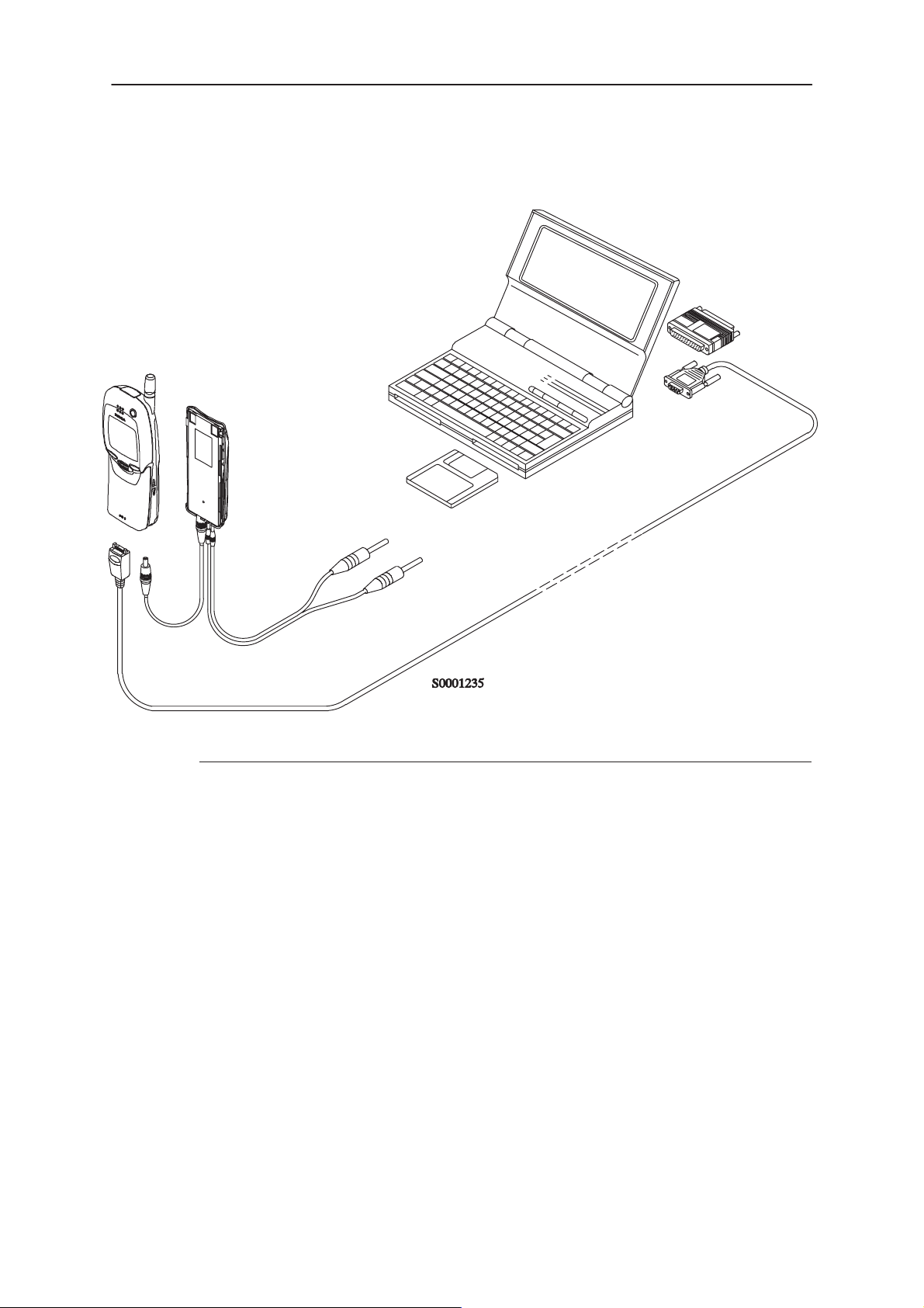
Equipment Setup for T uning a Phone without Removing Covers
4.
1.
5.
2.
3.
Item: Service accessory: Product code:
1 Service Battery BBD–3 0775071
2 DC Cable SCB–3 0730114
3 Service MBUS Cable DAU–9P 0730109
4 Software protection key PKD–1 0750018
5 Service SW diskette 3.5” 0774080
Issue 1 07/99
Page 11
Page 12
NSE–5
PAMS
Service Software Instructions
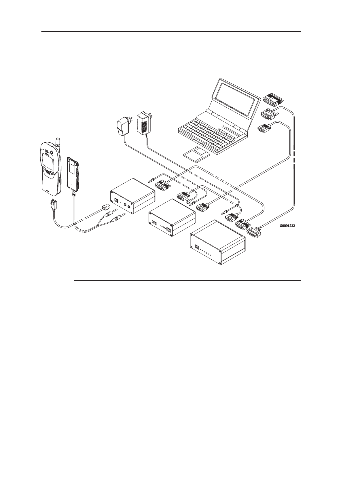
Flash Concept for NSE–5
12.
4.
6.
Technical Documentation
10.
13.
11.
9A.
7.
9B. 8.
5.
1.
2.
3.
Item: Service accessory: Product code:
1 Flash Loading Adapter FLA–5 0080178
2 Flash Security Box TDF–4 0770106
3 Prommer FPS–4S 0085095
4 Service Battery BBD–3 0775071
5 Service Cable SCH–5 0730098
6 DC Cable PCC–1B 0730053
7 D15 – D15 Cable AXS–5 0730091
(Included in FLA–5 sales pack)
8 Printer Cable (Included in FPS–4 sales pack) 0730029
9A D9 – D9 Cable AXS–4 0730090
(Included in FPS–4 sales pack)
9B D9 – D9 Cable AXS–4 0730090
10 Software protection key PKD–1 0750018
11 Service SW diskette 3.5” 0774080
12 Travel Charger ACH–6E (Euro) 0270381
Travel Charger ACH–6U (USA/Japan) 0270382
Travel Charger ACH–6X (UK) 0270380
13 AC Charger ACL–3E 0680015
(Included in FPS–4 sales pack)
Page 12
Issue 1 07/99
Page 13
PAMS
NSE–5
Technical Documentation
Service Software Instructions
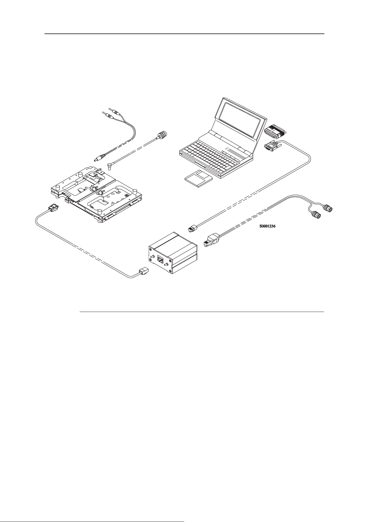
Tuning With Covers Off – Using Test–frame JBS–19
3.
4.
9.
6.
1.
8.
7.
5.
2.
Item: Service accessory: Product code:
1 Module Jig JBS–19 * 0770098
2 Service Audio Box JBA–4 ** 0770094
3 DC Cable PCS–1 0730012
4 External Antenna Cable XRC–1B 0730128
5 Service Cable SCH–5 ** 0730098
6 Service MBUS Cable DAU–9S ** 0730108
7 Audio Cable ADS–1 0730011
8 Software Protection Key PKD–1 0750018
9 Service SW diskette 3.5” 0774080
* The nominal operating voltage for JBS–19 is 3.6 V.
The supply voltage for JBS–19 must never exceed 5.0 V
** SCH–5, JBA–4, and DAU–9S can be replaced with DAU–9P
Issue 1 07/99
Page 13
Page 14
NSE–5
PAMS
Service Software Instructions
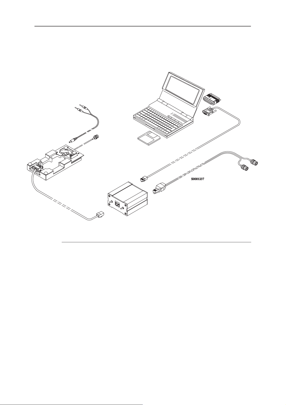
T uning With Covers Off – using Light Jig JBT–1
3.
4.
1.
Technical Documentation
8.
1.
5.
Item: Service accessory: Product code:
1 Light Module Jig JBT–1 * 0770109
2 Service Audio Box JBA–4 ** 0770094
3 DC Cable PCS–1 0730012
4 External Antenna Cable XRC–1B 0730128
5 Service Cable SCH–5 ** 0730098
6 Audio Cable ADS–1 0730011
7.
6.
2.
Page 14
7 Service MBUS Cable DAU–9S ** 0730108
8 Software Protection Key PKD–1 0750018
9 Service SW diskette 3.5” 0774080
* The nominal operating voltage for JBT–1 is 3.6 V.
The supply voltage for JBT–1 must never exceed 5.0 V
** SCH–5, JBA–4, and DAU–9S can be replaced with DAU–9P
Issue 1 07/99
Page 15
PAMS
NSE–5
Technical Documentation
Warranty Transfer
Service Software Instructions
1.
Item: Service accessory: Product code:
1 Warranty Cable SCH–6 0730099
Issue 1 07/99
Page 15
Page 16
NSE–5
PAMS
Service Software Instructions
Technical Documentation
Common Properties of the User Interface
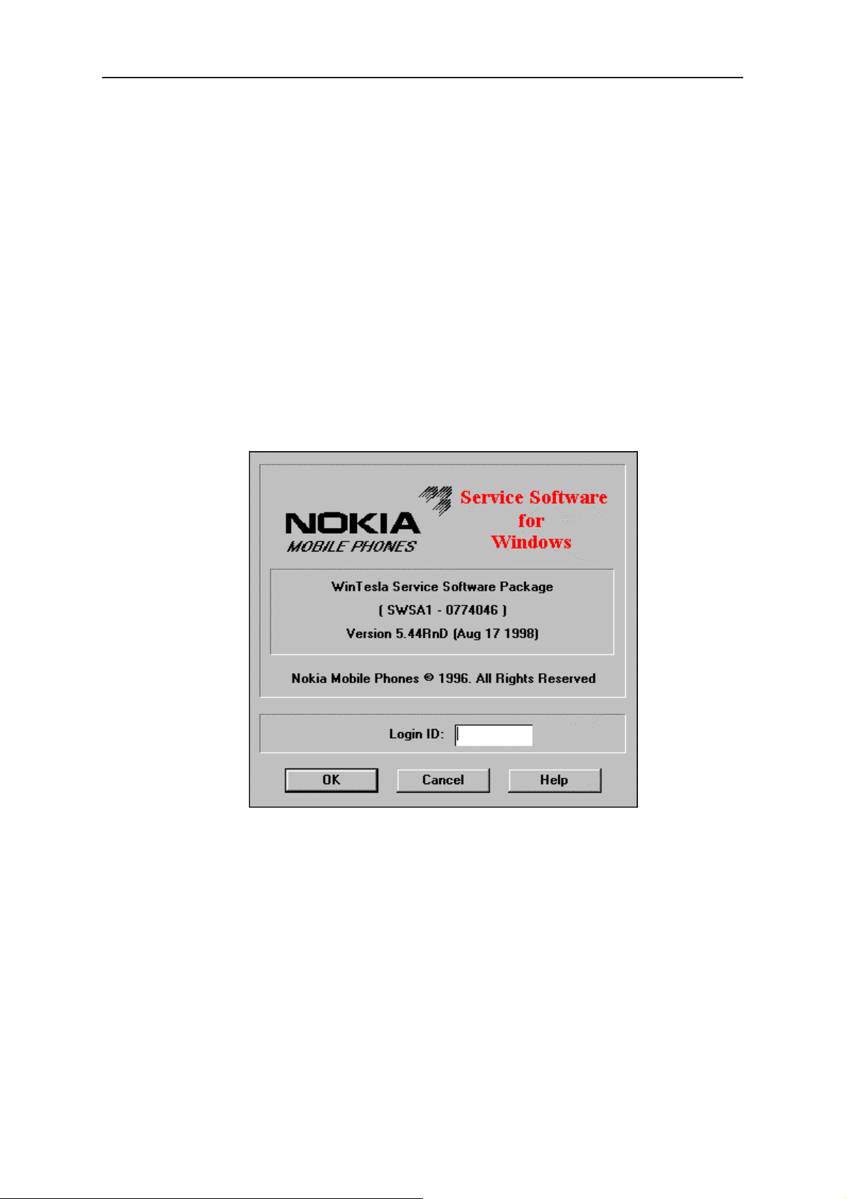
When the Service Software application is invoked, the Login dialog box
will be displayed on the screen.
The User Interface can be mouse driven or used without the use of a
mouse.
Login Dialog
When the Service Software application is invoked, by checking on the
Service Software icon, the Login dialog box will be displayed on the
screen.
Page 16
Nokia logo and application name bitmap (–)
Displays Nokia logo and name of the application.
Application version static text (–)
Contains the name and version of the application.
Copyright notice static text (–)
Copyright is informed as: “Nokia Mobile Phones (c) 1996. All
Rights Reserved”.
Login Box edit box (–)
The user Login ID edit box, where the user enters his faultlog
user name. (See Faultlog User Guide)
Issue 1 07/99
Page 17
PAMS
NSE–5
Technical Documentation
OK button (default key)
The user name is stored in memory and the dialog box is
closed. When the dialog box is closed, the application starts.
Cancel button (ESC)
The Dialog box is closed and application is started, but the
Faultlog feature is disabled.
Help button (F1)
Activates the Windows Help application and displays context
sensitive Help.
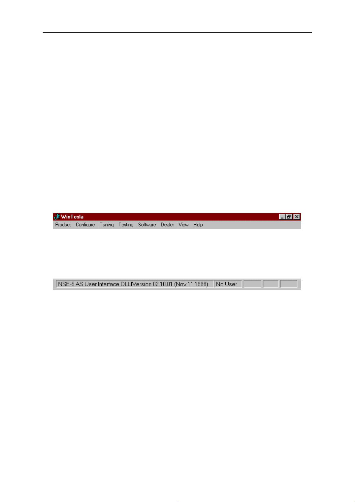
Main Window
Service Software Instructions
Title bar
The
title bar
A title bar contains the following elements:
• Application Control–menu button
• Maximise button
• Minimise button
• Name of the application
• Restore button
The properties of these elements and their usage is described in Ref 3–
Microsoft Windows Version 3.1 Users Guide chapter one (Windows
Basics) and chapter two (Application Basics).
is located at the top of the window.
Issue 1 07/99
Page 17
Page 18

NSE–5
PAMS
Service Software Instructions
Menu bar
The
menu bar
selections. The menu bar is a dynamic element and is dependent on the
dongle type fitted, and whether a phone is connected.
Underlined characters in menu names and options indicates that the
menu selection can be done by pressing
Options can also be selected by activating menu bar with
key ) and using arrow–keys to highlight the desired menu. In that case,
selection is done by pressing
Menus can also be selected by using the mouse as described in Ref
3–Microsoft Windows Version 3.1 Users Guide
Status bar
The
status bar
window. The status bar contains information about the latest
detected/selected phone type the software version of the product support
modules, ongoing events, and contain a set of status indicators.
is below the title bar and contains all available menu
is displayed at the bottom of the Service Software main
Enter
Technical Documentation
Alt+ underlined character
Alt
– key ( or
.
.
F10
The left area of the status bar describes the latest detected/selected
phone type, and gives the version of the product support modules.
The status bar texts are explained in detail in the description of each
command.
The right areas of the status bar indicate which of the following keys are
latched down:
Indicator Description
USER Entered Login ID.
CAP The Caps Lock key is latched down.
NUM The Num Lock key is latched down.
SCRL The Scroll Lock key is latched down.
Page 18
Issue 1 07/99
Page 19
PAMS
NSE–5
Technical Documentation
Menu
The Service Software package will have two menu bar configurations. The
first, is an abbreviated version that contains the minimum number of
menus that allows package configurations when a phone is NOT
connected. The second is described below:
The menu bar contains the following menus for the Service Software
package when a phone is connected:
• Product*
• Configure*
• Tuning
• Testing
• Software
• Dealer
Service Software Instructions
Product
• View
• Help*
* – always displayed, even if no phone is connected.
A menu is broken down into sections that are indicated with menu
separators. Each sections identifies a logical difference from itself and
other sections, i.e. between transmitter and receiver.
The menu lists will use the Microsoft [...] symbol after an item name to
indicate that selecting that item will NOT initiate an operation immediately,
i.e. a dialog box will be displayed for the user to select options or type in
data and press the OK button before the operation is performed.
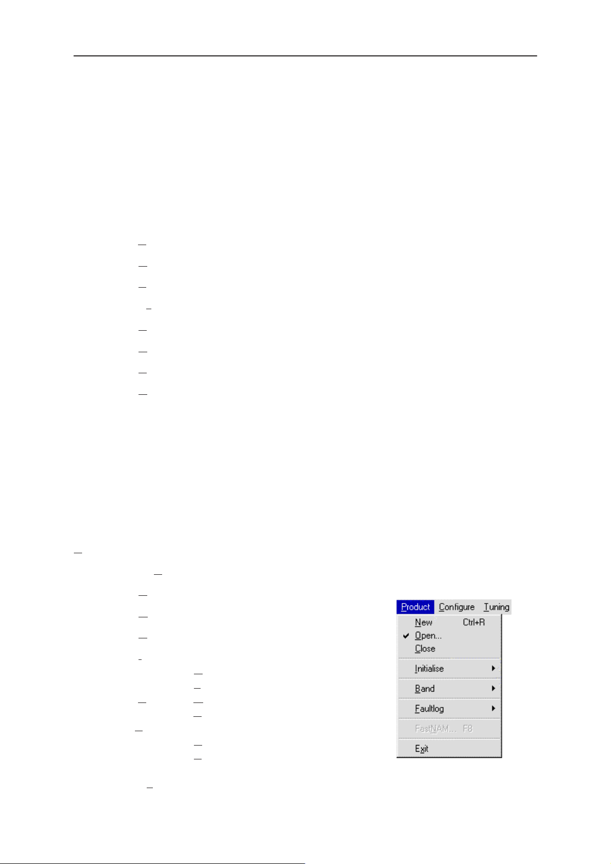
The Product menu contains the following menu items:
• New (Ctrl+R)
• Open...
• Close
• Initialize
• Normal Mode (F5)
• Local Mode (Shift+F5)
• Band • GSM
• PCN
•Faultlog
• Activate Faultlog...(F9)
• FastNAM – F8 (Disabled)..
• Exit (Alt+F4)
Issue 1 07/99
Page 19
Page 20
NSE–5
PAMS
Service Software Instructions
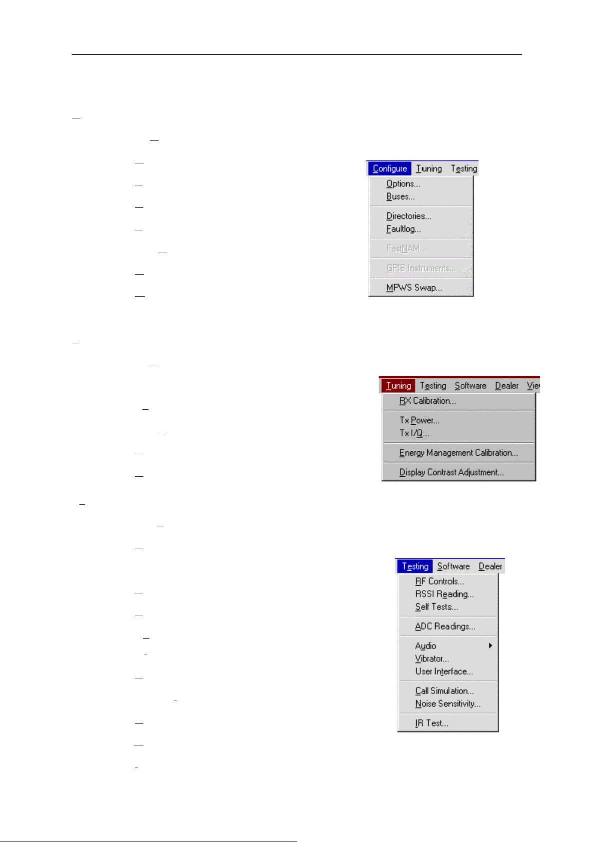
Configure
The Configure menu contains the following items:
• Options...
• Buses
• Directories...
• Faultlog...
• FastNAM (Disabled)
• GPIB Instruments (Disabled)
• MPWS Swap
Tuning
Technical Documentation
Testing
The Tuning menu contains the following menu sections:
• RX Calibration...
• Tx Power...
• Tx I/Q...
• Energy Management Calibration...
• Display Contrast Adjustment...
The Testing menu contains the following sections:
• RF Controls...
• RSSI Reading ...
• Self Tests
• ADC Readings
• Audio
- Internal
Page 20
• Vibrator
• User Interface
• Call Simulation
• Noise Sensitivity...
• IR Test
Issue 1 07/99
Page 21
PAMS
NSE–5
Technical Documentation
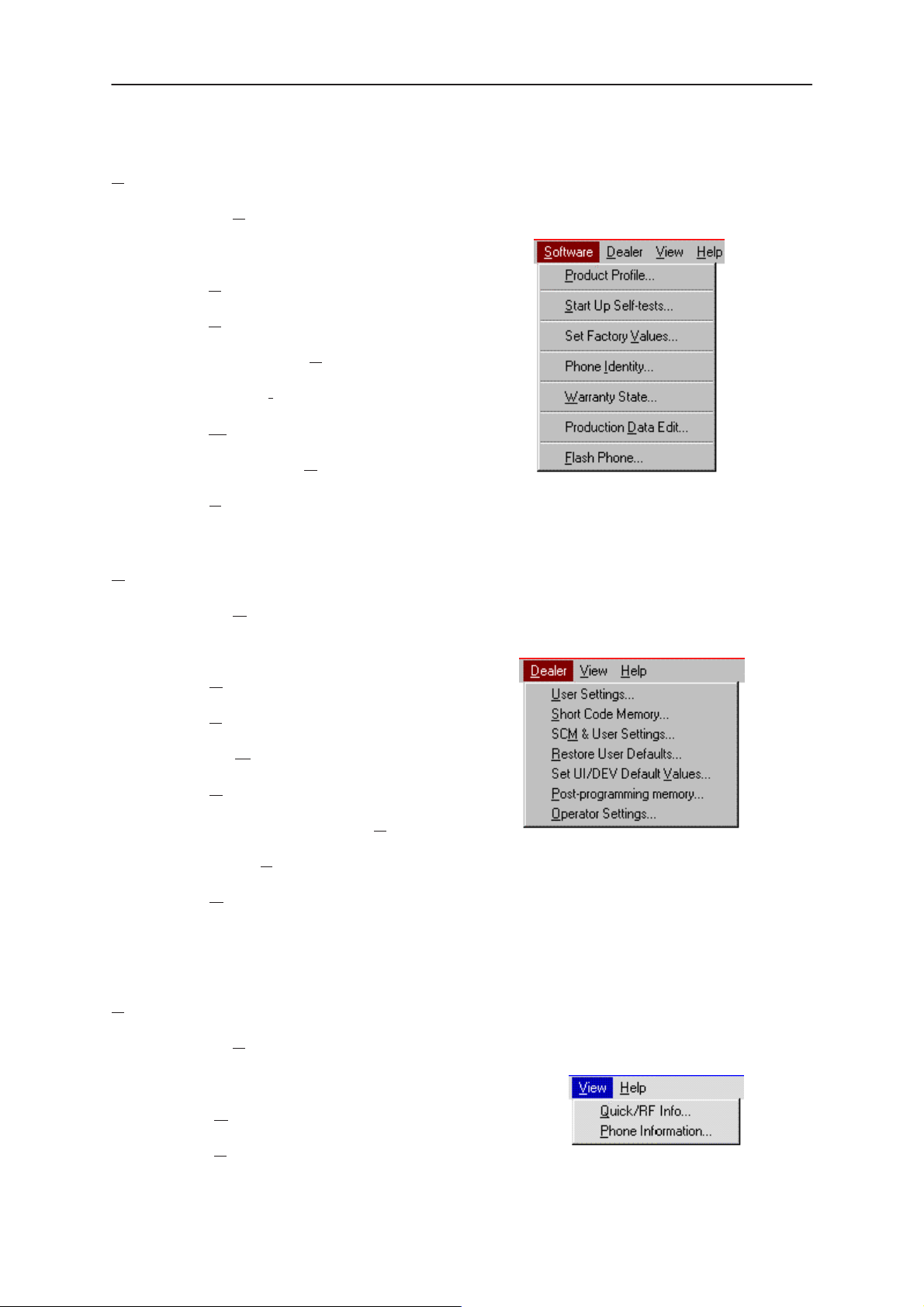
Software
The Software menu contains the following menu sections:
• Product Profile...
• Start Up Self–tests...
• Set Factory Values
• Phone Identity...
• Warranty State..
• Production Data Edit...
• Flash Phone...
Service Software Instructions
Dealer
View
The Dealer menu contains the following menu sections:
• User Settings...
• Short Code Memory...
• SCM & User settings ...
• Restore User Defaults...
• Set UI/DEV Default Values ...
• Flash PPM
• Operator Settings..
The View menu contains the following sections:
• Quick/RF Info...
• Phone Information...
Issue 1 07/99
Page 21
Page 22
NSE–5
PAMS
Service Software Instructions
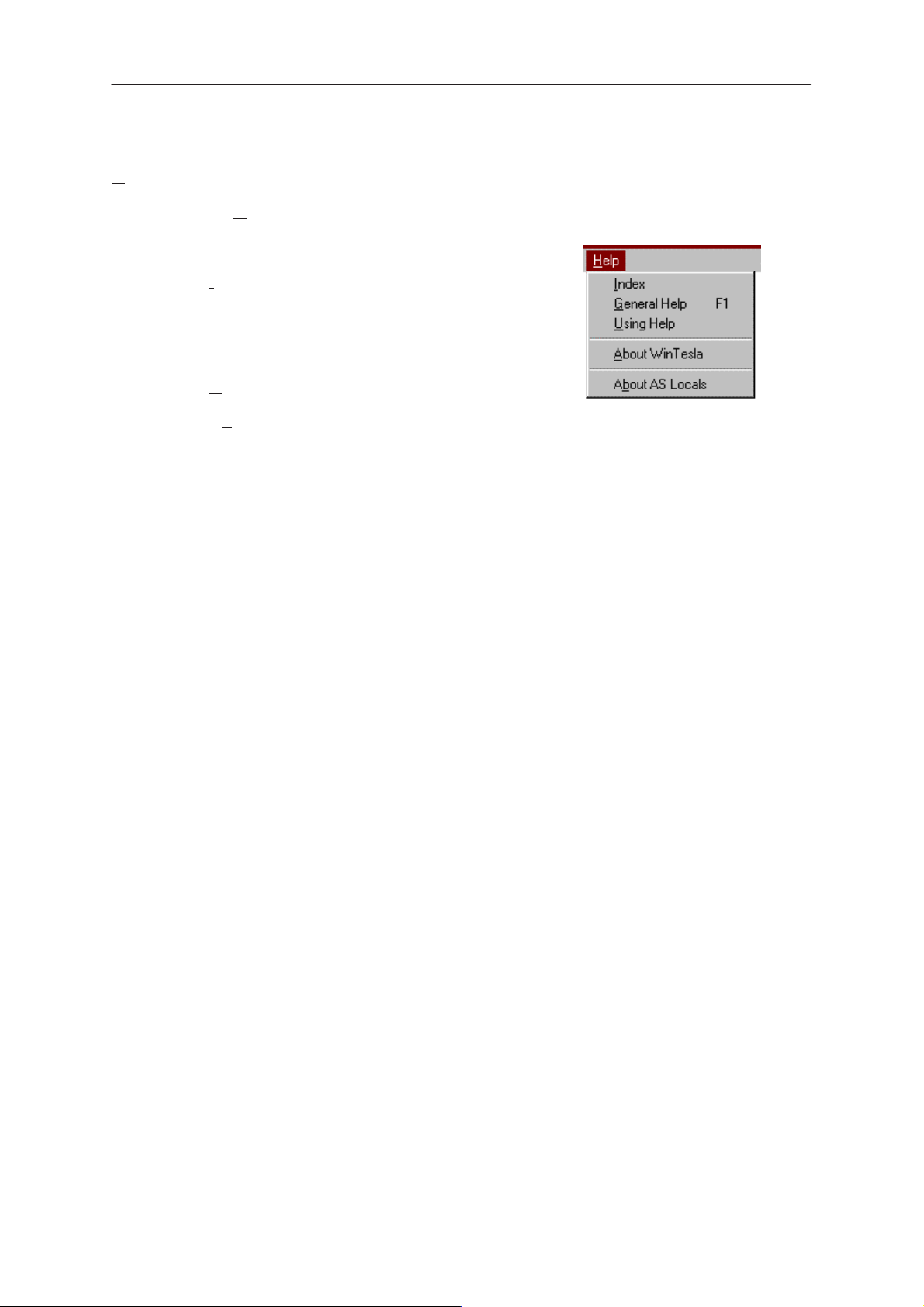
Help
The Help menu contains the following menu items:
• Index
• General Help (F1)
• Using Help
• About WinTesla
• About AS Locals
Mouse Cursors
The standards Windows pointer is used as the mouse cursor.
During time consuming tasks e.g. communication to phone, an hour glass
is shown informing the user that a task is in progress. The application
uses the hour glass cursor to inform user that the application has taken
the control and any actions from user will be ignored.
Technical Documentation
When a function is initiated, the hour glass will be displayed and when the
function has finished the mouse pointer will return to normal.
Page 22
Issue 1 07/99
Page 23

PAMS
NSE–5
Technical Documentation
Reserved Keys
The following Hot keys and Short Cut keys are reserved either as
Microsoft standard keys or as part of the Common Look and Feel.
Short Cut Function Keys
Key Description Defined by
F1 Context Sensitive Help Microsoft
F5 Normal Mode NMP
Shift+F5 Local Mode NMP
F8 FastNAM (disabled) NMP
F9 Activate Faultlog NMP
F10 Goto Menu Bar Microsoft
Service Software Instructions
Ctrl+F4 Close Active Window Microsoft
Alt Hot Keys
Key Description Defined by
Alt+F4 Exit Active Application Microsoft
Alt+H Help Microsoft
Ctrl Hot Keys
Key Description Defined by
Ctrl+N File – New Microsoft
Ctrl+O File – Open Microsoft
Ctrl+P File – Print Microsoft
Ctrl+R Product – New NMP
Shift Hot Keys
Key Description Defined by
Shift+F5 Local Mode NMP
Issue 1 07/99
Page 23
Page 24
NSE–5
PAMS
Service Software Instructions
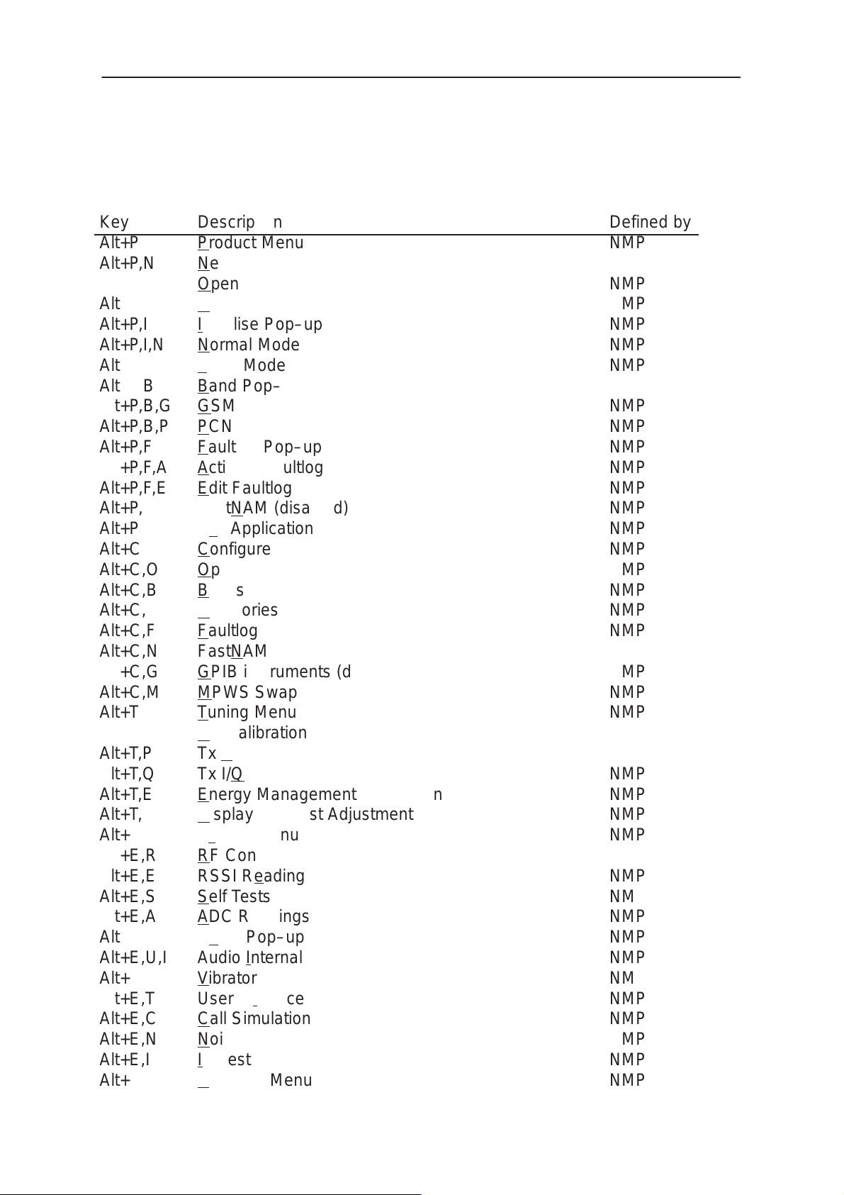
Key Strokes
Key
Alt+P
Alt+P,N
Alt+P,O
Alt+P,C
Alt+P,I
Alt+P,I,N
Alt+P,I,L
Alt+P,B
Alt+P,B,G
Alt+P,B,P
Alt+P,F
Alt+P,F,A
Alt+P,F,E
Alt+P,N
Alt+P,X
Alt+C
Alt+C,O
Alt+C,B
Alt+C,D
Alt+C,F
Alt+C,N
Alt+C,G
Alt+C,M
Alt+T
Alt+T,R
Alt+T,P
Alt+T,Q
Alt+T,E
Alt+T,D
Alt+E
Alt+E,R
Alt+E,E
Alt+E,S
Alt+E,A
Alt+E,U
Alt+E,U,I
Alt+E,V
Alt+E,T
Alt+E,C
Alt+E,N
Alt+E,I
Alt+S
Description
Product Menu
New
Open
Close
Initialise Pop–up
Normal Mode
Local Mode
Band Pop–up
GSM
PCN
Faultlog Pop–up
Activate Faultlog
Edit Faultlog
FastNAM (disabled)
Exit Application
Configure
Option
Buses
Directories
Faultlog
FastNAM (disabled)
GPIB instruments (disabled)
MPWS Swap
Tuning Menu
RX Calibration
Tx Power
Tx I/Q
Energy Management Calibration
Display Contrast Adjustment
Testing Menu
RF Controls
RSSI Reading
Self Tests
ADC Readings
Audio Pop–up
Audio Internal
Vibrator
User Interface
Call Simulation
Noise Sensitivity
IR Test
Software Menu
Technical Documentation
Defined by
NMP
NMP
NMP
NMP
NMP
NMP
NMP
NMP
NMP
NMP
NMP
NMP
NMP
NMP
NMP
NMP
NMP
NMP
NMP
NMP
NMP
NMP
NMP
NMP
NMP
NMP
NMP
NMP
NMP
NMP
NMP
NMP
NMP
NMP
NMP
NMP
NMP
NMP
NMP
NMP
NMP
NMP
Page 24
Issue 1 07/99
Page 25
PAMS
NSE–5
Technical Documentation
Alt+S,P
Alt+S,S
Alt+S,V
Alt+S,I
Alt+S,W
Alt+S,D
Alt+S,F
Alt+D
Alt+D,U
Alt+D,S
Alt+D,M
Alt+D,R
Alt+D,V
Alt+D,F
Alt+D,O
Alt+D,I
Alt+V
Alt+V,Q
Alt+V,P
Alt+H
Alt+H,I
Alt+H,G
Alt+H,U
Alt+H,A
Alt+H,B
Product Profile
Start–up Self Tests
Set Default Values
Phone Identity
Warranty state
Production Data Edit
Flash Phone
Dealer Menu
User Settings
Short Code Memory
SCM & User Settings
Restore User Defaults
Set UI/DEV Default Values
Flash PPM
Operator Settings
IWR Swap
View Menu
Quick/RF Info
Phone Information
Help Menu
Index
General Help
Using Help
About WinTesla
About AS Locals
Service Software Instructions
NMP
NMP
NMP
NMP
NMP
NMP
NMP
NMP
NMP
NMP
NMP
NMP
NMP
NMP
NMP
NMP
NMP
NMP
NMP
Microsoft
Microsoft
Microsoft
Microsoft
NMP
NMP
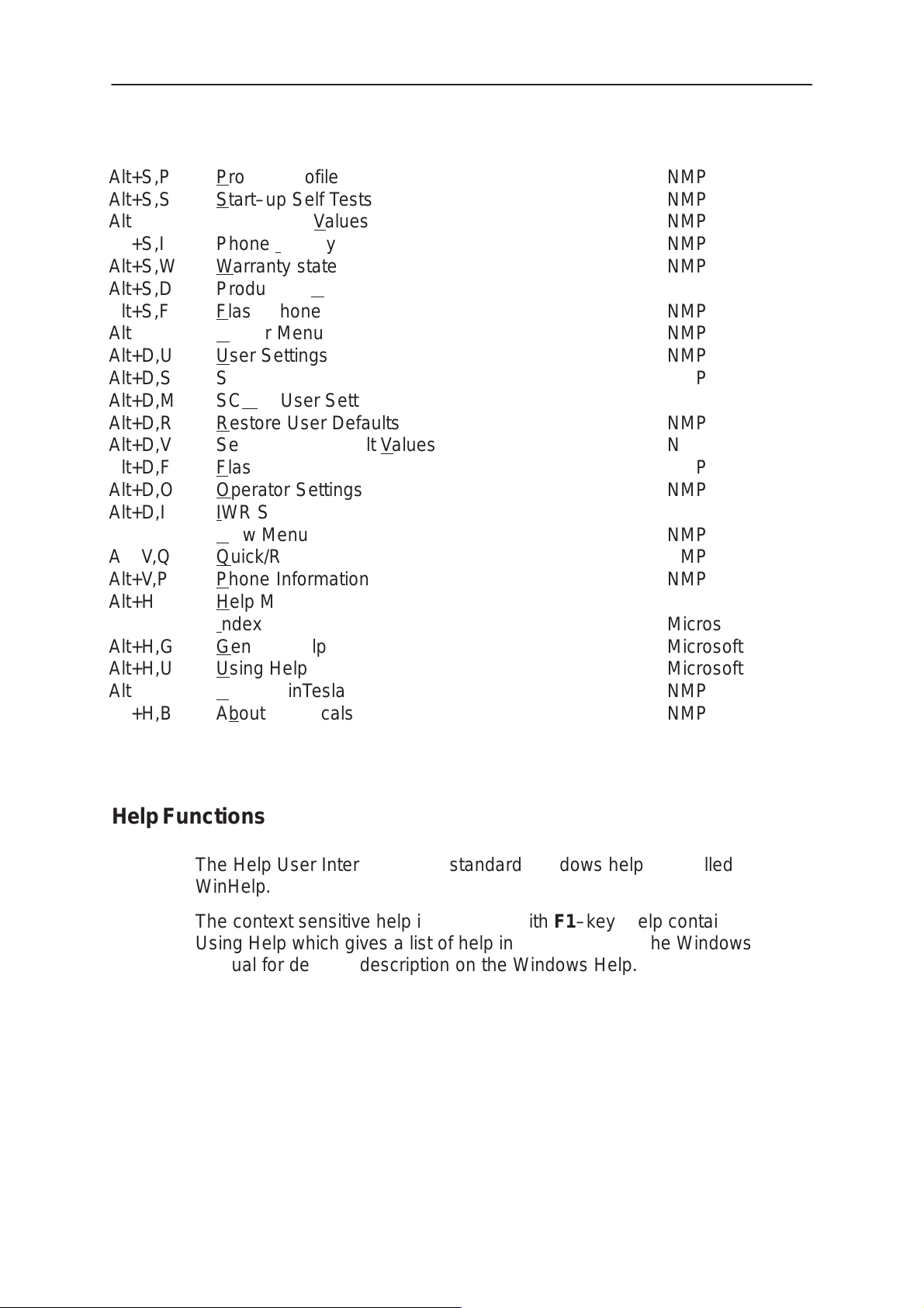
Help Functions
The Help User Interface is the standard Windows help tool called
WinHelp.
The context sensitive help is activated with F1–key. Help contains also
Using Help which gives a list of help indexes. Refer to the Windows
manual for detailed description on the Windows Help.
Issue 1 07/99
Page 25
Page 26

NSE–5
PAMS
Service Software Instructions
Dialog boxes
The Service Software application uses many different dialog boxes. Dialog
boxes are used to display data and prompt the user for input.
Dialog boxes are opened from menus or with shortcut keys. Dialog boxes
have different properties but some features are common.
Most service dialog boxes are modal, that is, the user will is not able to
start another operation without first closing the present dialog box.
All dialog boxes contain the following entities:
– Help button
– Title bar
– At least one button other than Help
– Application Close–menu Button
Technical Documentation
Common Dialog boxes
This sections describes the common dialog boxes used in the Service
Software package, and the context in which they are used.
Warning and Exclamation Message Box
When the user has made an illegal selection, a
Message Box
size of the dialog box may vary. This box is recognised by the ! icon.
The dialog box also contains an OK button and sometimes a Cancel
button.
OK button (default key): Acknowledges Warning / Exclamation and
Cancel button: Abandons the function and closes the
dialog will be opened and message text is displayed. The
continues. The dialog box is closed after
selection.
dialog box
Warning and Exclamation
Page 26
Issue 1 07/99
Page 27

PAMS
NSE–5
Technical Documentation
Information Message Box
Service Software Instructions
When the program has some information for the user, an Information
Message Box dialog will be opened and a text message displayed. the
size of the dialog box may vary. This box is recognised by the i icon.
The dialog box also contains an OK button.
OK button (default key): Acknowledges information and closes the
dialog box
Query Message Box
Confirmations and questions are asked in
a query message box
dialog box is recognized by the ?–icon.
. A query
The dialog box contains a Yes button, a No button, and a Help button.
Yes button (Alt+Y or Y) (default key):
No button (Alt+N or N):
Help button (Alt+H):
The buttons may also be OK and Cancel.
Error Message Box
Error message dialog boxes use the Error–icon. When a “Error”–dialog
box is shown, the current operation is terminated.
The dialog box has a description about the failed operation and reason.
Pressing F1 (Help) application opens the appropriate help topic that gives
information about recommended actions.
Accepts confirmation or question.
Denies confirmation or question.
Opens context sensitive help as F1–key does.
The dialog box also contains an OK button and sometimes a Help button.
OK button (default key):
Help button (Alt+H):
Issue 1 07/99
Acknowledges displayed information and terminate current op-
eration. The dialog box is closed after selection.
Open context sensitive help as F1–key does.
Page 27
Page 28

NSE–5
PAMS
Service Software Instructions
Custom Dialog boxes
All custom dialog boxes will contain the predefined buttons as defined
below in the section –
The buttons are mainly positioned down the right–hand side of the dialog
boxes. The default action will be OK, except where that default action
could result in an irretrievable failure.
All tuning dialogs that contain tuning results, will display the old tuned data
read from the phone before the tuning was performed, as well as the
newly tuned data.
List boxes will be used to display lists of data, such as tuning data, test
results etc.
The use of radio buttons defines the number of possible choices available
to the user.
Buttons
Technical Documentation
Buttons.
All buttons are of the Microsoft style.
In general, the default button is the action button, the Close button or the
Yes button, but this will depend on the context of the dialog box that the
button is associated with.
(action) button:
Accepts and validates entered settings and values and closes
the dialog. If the values have not been changed, then no action
will be taken. The status bar will reflect the status. The user is
only queried, if the settings or values accepted will over–write
data that CAN NOT be reproduced.
A greyed action button indicates that settings selected by the
user are not acceptable.
Close button:
Closes the current dialog box. Does not send or store anything
and closes the dialog. The Close button is only used for dia-
logs that do not set or change any data.
Cancel button (Esc):
Cancel operation. Does not send or store anything and closes
the dialog box.
Page 28
A greyed Cancel button indicates that it is not possible to quit
from this dialog box.
Yes button (ALT+Y or Y):
Replies Yes to a question asked of the user.
Issue 1 07/99
Page 29

PAMS
NSE–5
Technical Documentation
No button (ALT+N or N):
Replies No to a question asked of the user.
Help button (ALT+H):
Opens context sensitive help as F1–key does.
Reporting Status
The status bar is used to report the present status to the user. When a
feature is initiated, the status bar will be updated with a brief description of
the function. The status bar will also be updated at key points in a time
consuming function.
If an error is to be reported to the user, it is displayed in the status bar as
well as displayed in a common error dialog box. This will mean the user is
not delayed from progressing on to the next operation unless an error
occurs, in which case, the user will have to acknowledge the error by
pressing the OK button.
Service Software Instructions
Issue 1 07/99
Page 29
Page 30

NSE–5
PAMS
Service Software Instructions
NSE–5 Features
Product
New command
Activation Status Bar Text
Alt, P, N Scanning for product...
Ctrl+R
If phone is changed (with same phone type only serial number is
changed) phone will be initialised to normal mode. If phone is changed to
different phone type the current DLLs are unloaded and new ones are
loaded for that phone.
If the Quick/RF Info view is open, window will be automatically updated. If
Phone Information view is open, it will be automatically updated.
Technical Documentation
Open... command
Activation Status Bar Text
Alt, P, O Changing product support modules
Phone is set to normal mode.
Initialise... command
Activation Status Bar Text
Alt, P, I
Opens a submenu
Normal Mode
Activation Status Bar Text
Alt, P, N Initialising normal mode..,
F5
Page 30
When normal mode has been activated or program has been started,
self–test results will be asked from MCU. If any fault was found in the
tests, an error message is shown. If normal mode has been set
successfully (no self test error has been found), and paging listening has
been started, the used AFC value is requested from MS. Initialisation
routine checks phone’s cellular type and if unsupported phone is detected,
application unloads the DLLs.
Issue 1 07/99
Page 31

PAMS
NSE–5
Technical Documentation
The After Sales SW sets automatically the MS state to local mode when
needed. If phone identification view is open, window will be automatically
updated. Also if RF Information Window is open it will be updated to quick
info view.
When the user selects any of the following items, the MS–state is
automatically set to normal:
Testing Vibrator
Dealer Set UI/DEV Default Values
Local Mode
Activation Status Bar Text
Alt, P, L Initialising local mode....;
Shift+F5
Selection will change the MS–state to local. When the user selects any of
the following items the MS–state is automatically set to local:
Service Software Instructions
Tuning RX Calibration
Tuning Tx Power
Tuning Tx I/Q
Tuning Energy Management Calibration
Testing RF Controls
Testing RSSI Reading
Testing Self Tests
Testing Audio Internal
Testing Vibrator
Testing Call Simulation
Testing Noise Sensitivity
Software Warranty State
Dealer User Settings
The After Sales SW sets automatically the MS state to local mode when
needed.
Also if quick info view is open it will be updated to RF Information view.
Issue 1 07/99
Dealer Short Code Memory
Dealer Restore User Defaults
Page 31
Page 32

NSE–5
PAMS
Service Software Instructions
Band command
Activation Status Bar Text
Alt, P, B
Opens a submenu
GSM
Activation Status Bar Text
Alt, P, B, G
Selects the GSM band on the MS
PCN
Activation Status Bar Text
Technical Documentation
Alt, P, B, P
Selects the PCN band on the MS
Faultlog command
Activation Status Bar Text
Alt, P, F
Opens a submenu. Only enabled when a user has logged in.
Activate Faultlog
Activation Status Bar Text
Alt, P, F, A
F9
Activates the faultlog. Only enabled when a user has logged in.
Edit Faultlog
Activation Status Bar Text
Page 32
Alt, P, F, A
Allows user to edit faultlog entries. Only enabled when a user has logged
in.
Issue 1 07/99
Page 33

PAMS
NSE–5
Technical Documentation
FastNAM command
Activation Status Bar Text
Alt, P, N
F8
This menu is only enabled when FastNAM functionality is included in Win
Tesla.
Exit command
Activation Status Bar Text
Alt, P, X
Exits the WinTesla application.
Tuning
Service Software Instructions
General
All tuning operations of the NSE-5 are carried out using the service
software. The service software turns the phone into the local–mode, in
which the phone can be outwardly controlled via the MBUS interface.
Tuning is based on the software communicating with the D/A and A/D
converters of the phone. In some instances the phone processor will also
calculate the required correction parameter.
The tuning values of the phone reside in the emulated EEPROM. The
contents of the emulated EEPROM can be read by the service software
and saved as a file.
This is advisable when there is need to retain that information, e.g. in view
of replacement of the circuit. The program also enables writing the default
parameters on the emulated EEPROM, in which case all tuning steps
should be carried out.
RX Calibration... command
A GSM/PCN signal generator and an antenna cable is needed for the
calibration. Before starting the RX Calibration the active band must be set
to the GSM band.
Note: After the GSM calibration is performed it is important that the PCN calibration is
performed immediately afterwards.
Activation Status Bar Text
Alt, T,R Initialising local mode...;
Starts RX calibration.
Issue 1 07/99
Page 33
Page 34

NSE–5
PAMS
Service Software Instructions
The next automatic selections are made when this tuning function is
activated:
•Phone is set to local mode
•Update RF information window
The calibration is started automatically when RX calibration is entered.
The calibration is done in eleven steps:
User is requested to put signal generator to high input level
(read from .INI file).
Technical Documentation
When the user acknowledges by pressing OK, the calibration
with high input level is executed.
User is requested to put signal generator to low input level
(read from .INI file).
When the user acknowledges by pressing OK, the calibration
with low input level is executed.
The RX Calibration dialog will be shown when previous steps
are done. Select Save, to store the calibration in the phone.
Page 34
Issue 1 07/99
Page 35

PAMS
NSE–5
Technical Documentation
Service Software Instructions
Changing the band from GSM to PCN is done automatically.
Remember to change the band on the GSM signal generator.
User is requested to put signal generator to high input level
(Read from .INI file).
When the user acknowledges by pressing OK, the calibration
with high input level is executed.
Issue 1 07/99
Page 35
Page 36

NSE–5
PAMS
Service Software Instructions
User is requested to put signal generator to low input level
(Read from .INI file)
When the user acknowledges by pressing OK, the calibration
with low input level is executed.
The RX Calibration dialog will be shown when these steps are
done. Select Save, to save the calibration in the phone.
Technical Documentation
Page 36
Issue 1 07/99
Page 37

PAMS
NSE–5
Technical Documentation
During tuning, proceed as follows:
- Take care not to damage sensitive measuring instruments with excessive RF power.
- Carry out all tuning steps in the shortest possible time to avoid excessive heating of RF units.
- Perform all tuning steps in the order presented.
- Never try to mask a fault by tuning it out!
After the tuning has finished the software reports the following:
- AFC init value
- AFC slope
- PSW slope
- AGC DAC values and the corresponding voltages for each gain step (0
– 57dB)
Limits for the reported values
Service Software Instructions
If everything went well the reported values should approximately be the
following:
Parameter
AFC init value
AFC slope
PSW slope
AGC 0 dB
AGC 57 dB
Difference between the two neighbor AGC steps
Troubleshooting
If the calibration does not succeed the software normally reports ”Unable
to read data from phone” or ”Failed to set high reference” or ”Failed to set
low reference”. In this case check first the basic functionality of the
receiver chain: RF generator frequency set as in the calibration and level
for example to the high reference value.
Then go to the RSSI reading menu (under RF controls). If the reading is
very low there is something broken in the receiver and must be found by
measuring voltages and signal levels at different places (information of
these can be found elsewhere in this manual).
Low limit
-80
135
250
175
440
10
High limit
80
230
350
325
740
20
If the RSSI reading seems to be within 5 – 10 dB the same as the RF
in–put level check that the VCTCXO (G650) frequency is close enough
the wanted frequency. The easiest way to check this is by measuring the
UHF VCO (G550) frequency, because the absolute value of the deviation
is biggest there. In the GSM mid channel the UHF-VCO frequency should
be 2040.0 MHz. If the deviation is bigger than about +/-20 kHz it is
probable that the VCTCXO is not operating correctly.
Issue 1 07/99
Page 37
Page 38

NSE–5
PAMS
Service Software Instructions
If both of these (RSSI reading and the frequency) seem to be correct and
calibration still fails the most probable reason is that there is a little lack of
gain somewhere or the AGC gain control slope in N600 is out of the limits.
This can be verified by changing the generator reference levels from the
demanded ones in the calibration procedure in 1–dB steps up and down.
If the calibration goes through with some reference levels the corrective
action is most probably changing N500 or N600.
Dialog mode: modal
RX Calibration dialog has the following items:
AFC information box:
Shows AGC,DAC voltage.
AGC List box (ALT+A):
AGC, DAC, Voltage and Difference. The difference column shows the
difference between tuned DAC values and mean straight line calculated
from part slopes in dBs (see /1/). This can be calculated when all measurement results have been received from phone.
Technical Documentation
Repeat button (ALT+R):
The measurement can be started again by pressing this button.
Save button (ALT+S):
Dialog is closed and tuning
Cancel button (ESC):
Dialog is closed and tuning
When calibration is ended, the DAC value checking is made and if it is not
succeeded, error message is shown.
When exit is made, the next selections are set to the values which were
selected before this adjustment.
Operation Mode
Update RF Information window
The exit and the use of AGC–control values is done same way as exit
from power level tuning and power coefficient use.
is saved
to phone.
is not saved
to phone.
Page 38
Issue 1 07/99
Page 39

PAMS
NSE–5
Technical Documentation
Tx Power... command
An antenna cable, a GSM/PCN signal tester or either a Pulse Power
Meter or a spectrum analyser along with a 10dB attenuator is needed for
the tuning. If the tuning is performed with external voltage source, it shall
be set to 3.6 V. Before starting the TX Power tuning the active band is set
to the GSM band. For GSM the alignment channel is 60 (902 MHz) and
for PCN 700 (1747.8 MHz). The side channels for GSM are 1 (890.2 MHz)
and 124 (914.8 MHz) and for PCN 512 (1710.2 MHz) and 885 (1784.8
MHz).
Note:
In TX Power tuning the signal timing is irrelevant, and can not be measured since
the phone is set to local mode.
When using spectrum analyzer:
The following settings for the spectrum analyzer are recommended when
aligning the power levels: zero span, resolution and video bandwidths 1
MHz, input attenuation 40 dB, sweep time 1 ms, video triggering.
Service Software Instructions
Note! If spectrum analyzer is used in power level alignment the reading needs to be
calibrated with a power meter after every power up.
Start tuning
Activation Status Bar Text
Alt, T,P Initialising local mode....;
Starts TX power tuning.
The following automatic selection are made when the tuning function is
activated:
Active unit = TX
TX Power level = 19 (The lowest power level)
Operation mode = Burst
The TX power tuning is performed in the following 22 steps:
Select GSM band on the GSM/PCN signal tester or GSM/PCN
Power Meter. Select the GSM band in WinTesla in menu
Product, Band and GSM.
Compensate for antenna cable loss on the GSM/PCN signal
tester or GSM/PCN Power Meter. Typical values for a standard
cable is in GSM mode 0.6 – 0.7 dB cable loss.
Select measurement of average burst power on the GSM/PCN
signal tester or GSM/PCN Power Meter.
Select the menu Testing and RF Controls. And set:
- Active Unit = TX
- TX Data Type = Random
Issue 1 07/99
Page 39
Page 40

NSE–5
PAMS
Service Software Instructions
Select the menu Tuning and Tx Power.
Select the BASE power level by pressing Alt+L and scroll with
up/down arrow keys. Adjust the power level to be
approximately –35 dBm (measured on the GSM/PCN tester or
GSM/PCN Power Meter). Adjustment is done by pressing
left/right arrow keys.
Note: As a rule of thumb It can be done by adjusting the value until no
signal can be measured by the GSM/PCN tester and then weaken the
power level two steps more.
Select power level 19. Adjust the signal to 5 dBm. (According
to GSM specifications)
Select power level 15. Adjust the signal to 13 dBm. (According
to GSM specifications)
Select power level 5. Adjust the signal to 32.5 dBm. (According
to GSM specifications)
Technical Documentation
Select calculate to make WinTesla find the rest of the power
level values.
Note Calculated values can be checked after the calculation and fine–tuned if needed in
the same manner as previous power level tunings.
Save the TX power levels in the phone by pressing Save.
Page 40
Select PCN band on the GSM/PCN signal tester or GSM/PCN
Power Meter. Select the PCN band in WinTesla in menu
Product, Band and PCN.
Issue 1 07/99
Page 41

PAMS
NSE–5
Technical Documentation
Compensate for antenna cable loss on the GSM/PCN signal
tester or GSM/PCN Power Meter. Typical values for a standard
cable is in PCN mode 1.1 – 1.2 dB cable loss.
Select measurement of average burst power on the GSM/PCN
signal tester or GSM/PCN Power Meter.
Select the menu Testing and RF Controls. And set:
Select the menu Tuning and Tx Power.
Select the BASE power level by pressing Alt+L and scroll with
up/down arrow keys. Adjust the power level to be
approximately –35 dBm (measured on the GSM/PCN tester or
GSM/PCN Power Meter). Adjust by pressing ‘–‘ or ‘+’.
Note:As a rule of thumb It can be done by adjusting the value until no signal
can be measured by the GSM/PCN tester and then weaken the power level
two steps more.
Select power level 15. Adjust the signal to 2 dBm. (According
to GSM specifications)
Service Software Instructions
Select power level 11. Adjust the signal to 8 dBm. (According
to GSM specifications)
Select power level 0. Adjust the signal to 30 dBm. (According
to GSM specifications)
Select calculate to make WinTesla find the rest of the power
level values.
Note: Calculated values can be checked after the calculation and fine–tuned if needed in
the same manner as previous power level tunings.
Save the TX power levels in the phone by pressing Save.
Issue 1 07/99
Page 41
Page 42

NSE–5
PAMS
Service Software Instructions
During tuning, proceed as follows:
- Take care not to damage sensitive measuring instruments with excessive RF power.
- Carry out all tuning steps in the shortest possible time to avoid excessive heating of RF units.
- Perform all tuning steps in the order presented.
- Never try to mask a fault by tuning it out!
It is recommended that all the power–levels are separately aligned,
although there is a possibility to align only three and calculate the rest.
This is due to the fact that the calculation is not accurate enough.
Especially for the lowest power–levels in the PCN band, where the target
power–levels are NSE-5 specific.
Note Base level must be adjusted manually because the calculation most often fails.
Dialog mode: modal
Technical Documentation
TX Power Tuning dialog has following items:
Power Level & Coefficients list box (ALT+L):
The power is presented in GSM or PCN values. The base power is selected automatically when the dialog is opened. The test value is not
saved to the EEPROM. The test value can be changed during tuning as
other power coefficients and the program remembers its value when tuning function is activated later again.
Only three power coefficients (highest, third smallest and lowest) are
needed to tune (left justified Coefficients) and the rest of them are calculated.
The tuning position is highlighted and can be tuned with +/– keys or left/
right cursor keys.
Calculate button (ALT+A):
The calculation is activated with this button. The power coefficients which
are calculated from the tuned coefficients are displayed on the different
columns than the others. All values can be tuned if needed.
Base level calculation check box:
If this box is checked the base level is calculated.
Page 42
+/– buttons (+/– and left/right cursor keys):
+ and – buttons will cause power changing by 0.25dB steps. When these
keys are used the coefficient value is updated on the tuning window.
Save button (ENTER):
Dialog is closed and tuned values are
saved
to phone.
Issue 1 07/99
Page 43

PAMS
NSE–5
Technical Documentation
Cancel button (ESC):
Dialog is closed and tuning
When selections are used, the power value checking is made and if it is
not succeeded, error message is shown. The test checks that all power
coefficients are in descending order (same order than power levels).
If the power tuning function is ended and EEPROM values are not
received or EEPROM fault is noticed, an error message is shown.
When all power coefficients have such values that they don’t cause any
error messages, save can be made. The last used tuning power is in use
after exit.
The next automatic selection is made when this tuning function is ended:
Active Unit = RX
TX Power Level = (Off)
is not saved
Service Software Instructions
to phone.
Tx I/Q... command
A GSM/PCN signal tester or a GSM/PCN Spectrum analyser and an
antenna cable is needed for the tuning. Before starting the Tx I/Q tuning
the active band is set to the PCN band.
Note:: I/Q modulator alignments are performed in PCN band. If GSM band has been
selected and I/Q alignment is started, the service software asks to change to PCN band.
If the user wants to continue in GSM, the adjusted values can only be saved to PC
memory, not to phone’s emulated EEPROM. After changing to PCN band values from PC
memory are available, and if the modulator adjustment is good. The values can be saved
to phone’s emulated EEPROM. If tuning is tried in GSM mode, the following warning will
pop up:
Operation Mode = Burst
Activation Status Bar Text
Alt, T, Q Initialising local mode...;
This function is used for tuning TX I and Q branch DC offset, amplitude
difference and phase difference.
Issue 1 07/99
Setting RF Defaults...;
TX I/Q Tuning; Setting tuning on...;
Page 43
Page 44

NSE–5
PAMS
Service Software Instructions
The TX I/Q tuning is performed in the following 7 steps:
Connect the GSM/PCN signal tester or spectrum analyzer to
the phone antenna connector. When using spectrum
analyzer: The recommended spectrum analyzer settings are:
span 200 kHz, resolution bandwidth 10 kHz, video bandwidth 1
kHz, sweep 500 ms, input attenuation 30 dB.
Select PCN band on the GSM/PCN signal tester or GSM/PCN
Spectrum analyser. Select the PCN band in WinTesla in menu
Product, Band and PCN.
Select the menu Tuning and Tx I/Q.
Choose the option EEPROM values to tune the TX I/Q values
in the phone, and select OK.
Adjust the TX I DC Offset and TX Q DC Offset stepwise until
the carriers are suppressed as much as possible (Refer to the
drawing below). When tuning adjust the values slowly step by
step.
Technical Documentation
Page 44
Adjust the Amplitude difference and the Phase difference
stepwise until the side bands are suppressed as much as
possible (Refer to the drawing above). When tuning adjust the
values slowly step by step.
Store the selected values to the phone by pressing OK.
Issue 1 07/99
Page 45

PAMS
NSE–5
Technical Documentation
During tuning, proceed as follows:
- Take care not to damage sensitive measuring instruments with excessive RF power.
- Carry out all tuning steps in the shortest possible time to avoid excessive heating of RF units.
- Perform all tuning steps in the order presented.
- Never try to mask a fault by tuning it out!
Tuning targets:
The level of the carrier (center frequency CHF) should be at least 30 dB
down to the wanted sideband CHF – 67.71 kHz. The level of the
unwanted sideband CHF + 67.71 kHz should be at least 35 dB down to
the wanted sideband CHF – 67.71 kHz.
The user is first requested to select with which values the tuning is started
in Start Tuning dialog.
Service Software Instructions
Dialog mode is modal
Start Tuning dialog has following items:
Start Tuning with list box (ALT+S):
EEPROM values
Tuning values are loaded from the phones EEPROM.
Factory Default Values
Tuning values are loaded from phones Flash.
Current Values in PC Memory
Tuning values are loaded from programs internal memory.
OK button (ENTER):
Selects the memory where the start values for the tuning are placed,
closes the dialog box and continues with the TX I/Q dialog.
Issue 1 07/99
Page 45
Page 46

NSE–5
PAMS
Service Software Instructions
Cancel button (ESC):
Close the dialog box and cancel TX I/Q tuning.
Help button (ALT+H):
Context–sensitive help.
The next automatic selections are made, and the RF Information window
is updated when this function is activated:
- Band= PCN
- Active Unit= TX
- TX Data Type= Cont1
- TX Power level= 15
- Operation Mode= Burst
The TX I/Q Tuning dialog is opened.
Technical Documentation
Page 46
Dialog mode: modal
TX I/Q Tuning has following items:
Tune TX I DC Offset scroll bar (ALT+I):
The DC Offset is shown as percents (%) from the ± maximum value. 0%
means that there is no DC. The value range is –100%...100%. The value
is rounded to the nearest integer value.
Tune TX Q DC Offset scroll bar (ALT+Q):
The operation of this function is the same as one above, except with this
selection the Q branch DC Offset is tuned. The value range is
–100%...100%. The value is rounded to the nearest integer value.
Amplitude Difference scroll bar (ALT+A):
When this selection is made user can increase or decrease the amplitude difference within 0.1 dB steps. The value range is –1...1.
Issue 1 07/99
Page 47

PAMS
NSE–5
Technical Documentation
Phase Difference scroll bar (ALT+P):
When this selection is made user can increase or decrease the phase
difference within 0.5° steps. The current phase difference is shown on
the tuning window with numbers and bar figure. The value range is
–85...90.
Save button (ENTER):
Dialog is closed and tuning
Cancel button (ESC):
Dialog is closed and tuning
After each value change the new value is sent to the phone.
The next automatic selections are made, and the RF Information window
is updated when the TX I/Q tuning function is ended:
- Band= GSM
is saved
to phone.
is not saved
Service Software Instructions
to phone.
- Active Unit= RX
- TX Power level= (Off)
- Operation Mode= Burst
Energy Management Calibration... command
This command opens the Energy Management Calibration dialog box:
Issue 1 07/99
Page 47
Page 48

NSE–5
PAMS
Service Software Instructions
A DC power supply, a service battery and a 3–wire charger calibration
cable is needed for this calibration.
Note: The Energy Management Calibration process in WinTesla should only be used
when the factory calibration for some reason is not any longer valid in the phone. The
factory calibration of the phone energy management parameters are more precise, thus it
is possible to obtain better battery performance, when the calibration has been performed
in the factory.
Activation Status Bar Text
Alt, T,E Initialising local mode...;
The Energy Management Calibration is performed in the following 12
steps:
DC power supply is set to 10.5 Volts.
Mount the service battery on the phone
service battery with the phone by the charger calibration cable.
Connect the service battery to the DC power supply.
Select the menu Tuning and Energy Management Calibration.
The following dialog pop up:
and
connect the
Technical Documentation
Select OK. The phone is set to local mode, and the energy
management dialog pops up.
Select settings:
2. Battery voltage
3. Charger voltage
4. Battery size
5. Battery temperature
6. Charge current
Press Run. (If also the setting “Save without confirmation” is selected,
then steps 7 to 11 are not applicable.)
Page 48
Issue 1 07/99
Page 49

PAMS
NSE–5
Technical Documentation
The following dialog pop up:
Select Yes.
The following dialog pop up:
Service Software Instructions
Select Yes.
The following dialog pop up:
Select Yes.
The following dialog pop up:
Select Yes.
Issue 1 07/99
Page 49
Page 50

NSE–5
PAMS
Service Software Instructions
The following dialog pop up:
Select Yes.
When the previous steps are done, the phone energy
management is calibrated. Press Close to end the calibration
process.
The Energy Management Calibration dialog box contains the following
options:
Run button (ALT+R):
Energy management calibration is performed,
Technical Documentation
Close button (ENTER):
The dialog box is closed without performing energy management calibration. When closing the dialog the user is prompted to adjustthe power
supply to 8.0 Volts:
Help button (ALT + H):
Displays context sensitive help.
Page 50
Issue 1 07/99
Page 51

PAMS
NSE–5
Technical Documentation
Display Contrast Adjustment... command
This function is used for adjustment of the display contrast. No special
equipment is needed for display contrast adjustment.
Note: The display contrast values stored in the phone can not be read from WinTesla.
This means that if existing contrast settings are altered with this command, it is not
possible to go back to the previously stored values.
Activation Status Bar Text
Alt, T,D
Service Software Instructions
The command opens the Contrast adjustment dialog.
The Display Contrast Adjustment is performed in the following 5 steps:
Select menu item Tuning and Display Contrast Adjustment.
Select the default Basic and Fine adjustment settings in the
Edit boxes. Normally:
Basic adjustment = 3
Fine adjustment = 30
Press Apply. Since it is the first time the values are changed
since the dialog was opened a warning is displayed (If
selecting Yes it is
not
possible to return to previous values.):
Select Yes to modify the settings of the display contrast settings in the
phone.
Issue 1 07/99
Page 51
Page 52

NSE–5
PAMS
Service Software Instructions
Now use the scroll bar to fine–tune the contrast by using the
left/right arrow keys to adjust the contrast step by step. Do this
slowly to allow the changes to be reflected in the phone.
When adjustment is finished press OK to end the adjustment.
Dialog mode: modal
Phone Display Contrast Adjustment dialog has following items:
Basic adjustment edit box:
This is the rough setting of the display contrast. Valid values are between
0 and 7.
Fine adjustment edit box:
This is the fine setting of the display contrast. Valid values are between 0
and 63.
Technical Documentation
Contrast Scale scroll bar:
The user can stepwise adjust the display contrast, by use of the left/right
arrow keys.
OK button:
Applies contrast settings to the phone and closes the dialog box.
Cancel button:
Closes the dialog box without applying the contrast value to the phone.
Apply button (ALT+A):
Applies the entered values to the phone.
Help button (ALT+H):
Context sensitive help.
Page 52
Issue 1 07/99
Page 53

PAMS
NSE–5
Technical Documentation
Testing
The Testing sub menu offers functions for ME testing.
A GSM/PCN tester and an antenna cable is needed for this test.
RF Controls... command
Activation Status Bar Text
Alt, E,R RF Controls; Set test on...;
This function is used for RF testing.
Command opens RF Controls dialog, which contains data for testing and
adjustments.
Service Software Instructions
Dialog mode: modal
RF Controls dialog has following items:
Active Unit group:
RX radio button (ALT+R):
When RX is selected, the next functions are made:
Data transmission is deactivated
- TX power is deactivated
- Rf operation mode is continuous,
AGC is controlled
Issue 1 07/99
Page 53
Page 54

NSE–5
PAMS
Service Software Instructions
RX continuous mode channel is activated
- RF Information window is updated
The RX value is always given as default.
Note Function is activated immediately, Apply is not needed.
TX radio button (ALT+T):
When TX is selected, the next functions are made:
- Data transmission is activated
- If operation mode is continuous,
Operation mode is set to burst
- RF Information window is updated
Continuous mode radio button is disabled.
Note Function is activated immediately, Apply is not needed.
Technical Documentation
Operation Mode group:
Continuous radio button (ALT+C):
When
continuous
selection is used,
- synthesiser is set to constant frequency
- synthesiser channel number is as given with Continuous Mode Chan-
nel selection
- transmitter power is not connected
- if Active Unit is RX, AGC is controlled
Note Function is activated immediately, Apply is not needed.
Burst radio button (ALT+B):
When
burst
selection is used,
- synthesiser is controlled by using receiving/transmission/measuring
synthesiser control sequence
- synthesiser channel numbers are as given with Channel/Monitoring
Channel selections
- if Active Unit is TX, data (selected with TX Data Type) is sent and the
TX power is connected
Page 54
Note! Function is activated immediately, Apply is not needed.
Issue 1 07/99
Page 55

PAMS
NSE–5
Technical Documentation
TX Data Type drop list (ALT+D): With this value the data transmission
pattern can be selected. Possible options are:
- Random pattern
- Continuous zeroes
- Continuous ones
The TX Data Type is greyed when the active unit is RX.
TX Power Level edit box (ALT+X):
With this value is possible to change the transmission power. The user
can give the needed power value or select the test value, which is tuned
with TX power tuning function. The test value is found at the end of the
list.
TX Power have value
RX. When the TX power is tuned with test value (smallest value) the TX
Power has value
TEST
OFF
and is disabled (
.
Service Software Instructions
greyed
) when active unit is
Channel edit box (ALT+N):
User can enter here channel number that is used for both transmission
and receiving. The frequency of the selected channel is shown after
selection. The channel edit box is disabled (greyed) when the operation
mode is continuous.
Monitoring Channel edit box (ALT+M):
This field selects neighbour monitoring channel. The frequency of the selected channel is shown after selection. The monitoring channel edit box
is disabled (greyed) when the operation mode is burst.
Continuous Mode Channel edit box (ALT+O):
To this edit box user can type continuous mode channel which may have
all channel numbers. The continuous mode channel edit box is disabled
(greyed) when the operation mode is burst.
The used frequency depends on the Active Unit. If Active Unit is RX,
then RX frequency is used, else TX frequency. The frequency of the selected channel is shown after selection.
AGC Absolute edit box (ALT+L):
This selection allows user to edit AGC absolute value (value from A/D
converter).
When AGC Absolute value is changed the AGC dB value will be calculated depending on the AGC Absolute value. The AGC Absolute edit
box is disabled (greyed) when the operation mode is burst.
Issue 1 07/99
Page 55
Page 56

NSE–5
PAMS
Service Software Instructions
Front End On check box: (ALT+E)
This selection allows user to change whether the Front End amplifier is
On or Off. The Front End On check boxis disabled (greyed) when the
operation mode is burst.
AGC edit box (ALT+G):
This selection allows user to edit AGC value in dB
AFC edit box (ALT+F):
This selection allows the user to edit the AFC slope in DAC values.
AGC value is shown only when its value is controlled by PC. When Ac-
tive Unit has value RX and Operation Mode is continuous, AGC is controlled by PC except when next adjustment functions are activated:
RSSI Calibration
Technical Documentation
AFC Diagram
Apply button (ALT+A):
Accepts entered values and validates them. After validation application
sends corresponding messages to ME. Closes dialog and updates Info
Window.
Note Active Unit and Operation mode are not send with because they are activated
immediately.
Set Defaults button (ALT+S):
Sets the current values as default Rf Control values.
Get Defaults button (ALT+U):
Gets default Rf Controls values as current values.
The next automatic selection is made when Quick testing function is
ended:
Active Unit = RX
Update RF Information window
Page 56
Issue 1 07/99
Page 57

PAMS
NSE–5
Technical Documentation
The next table shows the dialog’s properties on different situations:
ACTIVE UNIT = TX:
TX Data Type: Updated
AGC values: Greyed
Monitoring Channel: Greyed
OPERATION MODE = BURST:
TX Power Level: Updated
Continuous Mode Channel: Greyed
Channel: Updated
ACTIVE UNIT = RX:
TX Data Type: Greyed
TX Power Level: BASE, Greyed
Service Software Instructions
Operation Mode = Burst:
AGC values: Greyed
Continuous Mode Channel: Greyed
Channel: Updated
Monitoring Channel: Updated
OPERATION MODE = CONT:
AGC values: Updated
Continuous Mode Channel: Updated
Channel: Greyed
Monitoring Channel: Greyed
RSSI Reading... command
A GSM/PCN signal generator and an antenna cable is needed for this
test.
Activation Status Bar Text
Alt, E,E RSSI reading from ME...
Command opens RSSI Reading dialog:
Dialog mode: modal
RSSI value is read continuously until user presses ESC–key or Close
button to cancel reading.
Issue 1 07/99
Page 57
Page 58

NSE–5
PAMS
Service Software Instructions
RSSI Reading dialog has following items:
Close (ENTER) button:
anything to phone.
Technical Documentation
Closes the RSSI Reading dialog. Does not send
Help button:
Self Tests... command
Activation Status Bar Text
Alt, E,S MCU Self–tests; Reading from ME...
Command is used for reading self test results and running self tests.
Context sensitive help.
Page 58
Issue 1 07/99
Page 59

PAMS
NSE–5
Technical Documentation
When the selection is made, the test result is read from ME. The test result will be shown to the user within MCU Self–test dialog.
Service Software Instructions
Dialog mode: modal
MCU Self–test dialog has following items:
Tests list box (ALT+T):
The field ”(p)” in the screen example means that the test is also run in
power up. The field “(/s)” means that this test is selectable one.
Test states are updated according to results received from the phone.
Possible test states will be one of the next:
Passed
Failed
No response
Not executed
Not valid
RUNNING....
Note that power–off test have no values, because if test has been passed, power has
been turned off. If power–off test fails a special error message window is shown. If no
response is received to power off test message in a few seconds, the user is informed by
Issue 1 07/99
Page 59
Page 60

NSE–5
PAMS
Service Software Instructions
special info window, where user is asked to turn the power on and then press the return
key.
Note also that power–off test (if passed) turns power off and power should be
reconnected by using the phones keypad after the successful test. After the power has
been connected to phone, the normal start–up routines are made and the self–test
results are shown in the MCU self–tests menu (i.e. all other than power–up self–tests are
in Not executed state after the power–up routines).
Run button (ALT+R):
User can select desired test from list and hit Run button. When user selects test to be run the text
test is run. When results are received the test state field is updated according to the result.
If no response was received in the defined time, a
be shown and the test state is changed to
local mode if it is not already there.
RUNNING...
Technical Documentation
is shown in test state field and
error message box
No response
. Phone is set to
will
Run All button (ALT+A):
User can run all listed tests. The text
field and test is run. When results are received the test state field is updated according to the result. When state field is updated application
moves to next test and repeats previous cycle. Phone is set to local
mode if it is not already there.
Supported Self Tests
The following tests are available:
1 MCU ROM Checksum................
2 MCU RAM Interface...............
3 MCU RAM Component...............
4 MCU EEPROM Interface............
5 MCU EEPROM Component............
6 RTC Battery.....................
7 CCONT Interface.................
RUNNING...
is shown in test state
Page 60
8 A/D Converter...................
9 SW Reset........................
A Power Off.......................
B Security Data...................
C EEPROM Tune Checksum............
D PPM Checksum....................
Issue 1 07/99
Page 61

PAMS
NSE–5
Technical Documentation
E MCU Download DSP................
F DSP Alive.......................
G COBBA Serial.......................
H COBBA Parallel.....................
I EEPROM Sec Checksum................
J PPM Validity..................................
K Warranty State..............................
ADC Readings... command
Activation Status Bar Text
Alt, E,A ADC Readings; Set test on...
Service Software Instructions
ADC Readings; Reading from ME....
Command is used to read and show A/D values from phone.
Command opens ADC Readings dialog.
Dialog mode: modal
ADC Readings dialog has static text field where measurements are
updated to window every one second.
ADC Readings dialog has following items:
Close (ENTER) button:
Closes the ADC Readings dialog. Does not send anything to phone.
Help button: (ALT+H) .
Context sensitive help
Issue 1 07/99
Page 61
Page 62

NSE–5
PAMS
Service Software Instructions
Following a/d readings are measured:
–Battery Voltage.........
–Battery Temperature.....
–Charge Voltage..........
–Charge Current..........
–Battery Type............
–Acessory Detection......
–RSSI....................
–VCXO Temperature........
–Hook Informaton........
Audio... command
Activation Status Bar Text
Technical Documentation
Alt, E,U
Opens a submenu which contains following options:
Internal Audio Loops
An audio cable, a function generator, an oscilloscope, a multimeter, a
headset and an audio box is optional equipment for the audio tests.
Activation Status Bar Text
Alt, E,U,I Initialising local mode....
Command is used for making internal audio loop tests in Internal Audio
Loops dialog.
Internal Audio Loops; Set test on....
Page 62
Issue 1 07/99
Page 63

PAMS
NSE–5
Technical Documentation
Service Software Instructions
Dialog mode: modal
Internal Audio Loops dialog has following items:
Buzzer Volume group:
Next three different values can be selected for Buzzer volume:
Volume On radio button (ALT+V):
Turns buzzer on.
Volume Off radio button (ALT+O):
Turns buzzer off.
Level drop down list (ALT+L):
Sets level of a buzzer. Allowed range 0...127
Frequency edit box (ALT+Q)
Sets the sound frequency in Hz
Internal Audio Loop group:
Input group:
Next two different values can be selected for input:
Internal radio button (ALT+I):
Turns internal input.
Issue 1 07/99
Page 63
Page 64

NSE–5
PAMS
Service Software Instructions
External radio button (ALT+E):
Turns external input.
Headset radio button (ALT+A):
Turns headset input.
Output group:
Next two different values can be selected for output:
Internal radio button (ALT+T):
Turns internal output.
External radio button (ALT+X):
Turns external output.
Headset radio button (ALT+D):
Turns headset output.
Technical Documentation
Loop group:
Next two different values can be selected for loop:
Off radio button (ALT+F):
Turns audio loop off.
On radio button (ALT+N):
Turns audio loop on.
When dialog is closed, the Buzzer Volume is switched off. Also internal
audio loop is turned off.
Vibrator......command
Activation Status Bar Text
Alt, E, V Initialising local mode....
Command used to test vibrator functionality
Page 64
Issue 1 07/99
Page 65

PAMS
NSE–5
Technical Documentation
Dialog mode: modal
Test of vibrator dialog has following items:
Vibrator is currently status text:
Displays the current status of the vibrator. Possible statuses are:
- Activated
- Deactivated
Activate button (ALT+A):
Activates the vibrator.
Deactivate button (ALT+D):
Deactivates the vibrator.
Close button (ESC):
Deactivates the vibrator, set the phone in normal mode and closes the
dialog.
Service Software Instructions
Help button (ALT+H):
Context sensitive help.
User Interface... command
Activation Status Bar Text
Alt, E,T User Interface Test; Set test on
Command is used for making display tests in Display Tests dialog.
Dialog mode: modal
Display Tests dialog has following items:
1. Test Pattern radio button (ALT+1):
In test display 1 the display is filled with chessboard letters.
2. Test Pattern radio button (ALT+2):
In test display 2 the display is filled with inverse chessboard letters.
Issue 1 07/99
Page 65
Page 66

NSE–5
PAMS
Service Software Instructions
Close button (ENTER):
Clears the display and closes the dialog. To get normal display, set the
phone in normal mode.
Help button (ALT+H):
Context sensitive help.
Call Simulation... command
Activation Status Bar Text
Alt, E, C Initialising local mode
Command is used for making call simulation. Function opens Call
Simulation dialog.
Technical Documentation
Setting RF Defaults
Call Simulation; Set test on
Page 66
Dialog mode: modal
Call Simulation dialog has following items:
TX Power Level edit box (ALT+T):
All power levels can be selected. This updates same parameter as TX
Power Level in the RF Controls dialog. Note that TEST value cannot be
selected. If TEST value was in use when Call simulation menu selected,
power level is changed to smallest value.
Channel edit box (ALT+C):
This tells the normal operating RF channel number. Normal GSM/PCN
channel numbers can be selected.
Issue 1 07/99
Page 67

PAMS
NSE–5
Technical Documentation
Same channel is used both for transmission and receiving. This updates
same parameter as Channel in the RF–Controls dialog.
Channel 1,2,3,4,5,6 edit box (ALT+1,2,...):
Channels for monitoring are specified with these six selections. All
GSM/PCN channel numbers can be used. If more than one selection has
same number, the monitoring channel list (neighbour list) will have less
than 6 selected channels. The minimum number of monitoring channels is
one (all channels have same value). The monitoring channel can also
have same value as normal operating channel.
The first monitoring channel updates same parameter as Monitoring
Channel in the RF–Controls dialog.
Apply button (ALT+A):
Validates and sends entered data to ME.
Set Defaults button (ALT+S):
Sets current values as default Call Simulation values.
Service Software Instructions
Get Defaults button (ALT+G):
Gets default Call Simulation values as current values.
Noise Sensitivity... command
A GSM/Signal generatorand an antenna cable is needed for this test. The
active band must be set to the GSM band.
Activation Status Bar Text
Alt, E, N Initialising local mode...;
Command is used for noise sensitivity measurement.
The next automatic selections are made when this tuning function is
activated:
- Active unit = RX
- Operation mode= Burst
- AGC value = 81 dB
Before function opens Noise Sensitivity dialog application prompts:
Noise Sensitivity; Set test on...;
Issue 1 07/99
Page 67
Page 68

NSE–5
PAMS
Service Software Instructions
Then application opens Noise Sensitivity dialog:
Dialog mode: modal
Technical Documentation
Noise Sensitivity dialog has following items:
Measurements group:
Clipping distance is the difference to the signal clipping value. SNR is
measured in an AD converter. Sensitivity is a calculated value based on
the measured SNR value.
The last value on the display is signal power difference between I and Q
branch. The numbers are shown in 0.1dB accuracy. The error messages,
”OUT OF RANGE”, are shown only if the SNR and/or amplitude difference
values are not acceptable.
Signal/Noise radiobutton (ALT+S/ALT+N):
When buttons are pressed, the RX I and Q burst data is asked, text
”SIGNAL MEASURING...” or ”NOISE MEASURING...” will come to the
measurement group window. The power level value should be –92 dBm
during signal measurement.
When signal data is received, distance to clipping signal level is shown as
dBs on the display. When either signal or noise measurement results are
received ”MEASURING” text is removed and measurements are updated
to screen. When both measurements (signal and noise) are done at least
once, the signal to noise relation and difference are also shown on the
display.
Page 68
When exit is made, the next selections are set to the values which were
selected before this adjustment.
- Active unit
- Operation mode
- AGC value
Issue 1 07/99
Page 69

PAMS
NSE–5
Technical Documentation
IR Test... command
A Combox and an infrared test cable is needed for this test.
Activation Status Bar Text
Alt, E,I IR test; Set test on...;
Command is used for making IR module test. Function opens IR Test
dialog:
Service Software Instructions
Dialog mode: modal
IR Test dialog has following items:
Result box:
Result can be OK/FAILED
Test button (ALT+T):
Starts IR Test.
Close button (ENTER):
Closes the IR Test dialog.
Help button (ALT+H):
Context sensitive help.
Issue 1 07/99
Page 69
Page 70

NSE–5
PAMS
Service Software Instructions
Software
Product Profile... command
Activation Status Bar Text
Alt, S,P Product Profile; Reading from ME...
Function is used for making product profile settings.
When command is activated the product profile information is read from
EEPROM and Product Profile dialog is opened.
Technical Documentation
Page 70
Dialog mode: modal
Product Profile dialog has following items:
Settings list box (ALT+E):
A list where user can select desired setting.
User can change settings in the Options drop list.
Options drop list (ALT+O):
List allows user to set options to each settings which are listed in Set-
tings list box.
Save button (ENTER):
Selections are accepted and saved to EEPROM.
Cancel button (ALT+C):
Selections are ignored and control is returned back to main menu.
Issue 1 07/99
Page 71

PAMS
NSE–5
Technical Documentation
Help button (ALT+H):
Context sensitive help.
Save File button (ALT+A):
Save settings to a file on the PC.
Load File button (ALT+O):
Load settings from a file on the PC.
Start Up Self–tests... command
Activation Status Bar Text
Alt, S,S MCU start Up Self–Tests.
Function is used for changing the state of the EEPROM selectable tests in
MCU Start Up Self–tests dialog.
Service Software Instructions
Dialog mode: modal
MCU Start Up Self–tests dialog has following items:
Tests list box (ALT+T):
When dialog is opened, the previous values will be read from the MCU
EEPROM and shown on the list box.
Status group:
When radio button On is selected, the test will be run every time when
automatic start up self–tests are activated (e.g. in power up).
OK button (ENTER)
Selections are accepted and saved to EEPROM. A power up routine is
made to phone.
Cancel button (ESC)
Selections are ignored and control is returned back to main menu.
Issue 1 07/99
Page 71
Page 72

NSE–5
PAMS
Service Software Instructions
Selectable Start–Up self tests:
- PPM V alidity
- A/D Converter
Set Factory Values... command
Activation Status Bar Text
Alt, S, V Setting
Default Factory Values; Initialising normal mode...;
Application does not ask confirmation. Next kind of text will be shown to
user:
“Setting UI and SCM Factory values...”
Technical Documentation
Page 72
Dialog mode: modal
Default Factory Values dialog has following items:
Settings list box:
Contains the selectable factory values.
Set button (ALT+S)
Sets the selected factory value to phone. Before setting software asks
confirmation:
Issue 1 07/99
Page 73

PAMS
NSE–5
Technical Documentation
Cancel button (ALT+C)
Closes the Default Factory Values dialog.
Help button (ALT+H):
Context sensitive help.
Phone Identity... command
Activation Status Bar Text
Alt, S,I Phone Identity: reading from ME...
Function is used to edit phone identity. With this dialog IMEI or SIM locks
may be changed in following manner:
– current phone information is read from phone
– user edits User Name (and IMEI, Product Code and Product Id, if they
were not read correctly from phone)
Service Software Instructions
– dialog information is saved to file, which is sent to secure place where
actual programming information may be constructed
– programming information is got from secure place in an other file, which
is loaded to dialog
– program checks input values and if they are correct programming
information is written to phone
Function opens Phone Identity dialog.
Issue 1 07/99
Dialog mode: modal
Page 73
Page 74

NSE–5
PAMS
Service Software Instructions
Phone Identity dialog has following items:
User Name edit box (ALT+U):
Field where user can enter user identification.
IMEI edit box (ALT+I):
Field where user can enter IMEI value. Field can contain up to 40 digits.
This field is automatically filled, if ME is connected to the PC when dialog
is loaded.
Product Code edit box (ALT+P):
Field where user can enter Product Code value.
This field is automatically filled, if ME is connected to the PC when dialog
is loaded.
Technical Documentation
MS Id edit box (ALT+M):
Field where user can enter MS Id corresponding programming data. This
field is automatically filled, if ME is connected to the PC when dialog is
loaded.
Product Id edit box (ALT+R):
Field where user can enter Product Id. This field is automatically filled, if
ME is connected to the PC when dialog is loaded.
Dongle serial nr edit box (ALT+N):
Field where the user can enter the dongle number. This field is automatically filled when opening the dialog.
Data edit box (ALT+A):
Field where user can enter Data entry. This field is automatically filled,
when file is loaded or data is saved.
IMEI radio button (ALT+E):
File and ME operations contains only IMEI data.
Page 74
SIM Lock radio button (ALT+O):
File and ME operations contains only SIM Lock data.
IMEI Programming Data edit box (ALT+G):
IMEI programming data is read from file or entered by user to this field.
Issue 1 07/99
Page 75

PAMS
NSE–5
Technical Documentation
SIM Lock Programming Data edit box (ALT+D):
SIM Lock programming data is read from file or entered by user to this
field.
Close button (ESC):
Cancels all edits and does not save values to phone.
Help button (ALT+H)
Opens a help text.
Write button (ALT+W):
Writes programming data to phone. Actions are selected with Action
Selection radio button.
Read button (ALT+R):
Reads identification data from phone and shows it in dialog controls.
Needed data is selected by Action Selection radio button.
Service Software Instructions
Save File... button (ALT+S):
Writes a file containing data needed by security place application to
create needed programming data. File is selected with File Save As dialog.
Load File... button (ALT+L):
Reads a file containing data needed to program selected data. File is selected with File Open dialog.
Warranty State... command
Activation Status Bar Text
Alt, S, W Initialising local mode
Command used to read warranty information from MS
Warranty State; Reading from ME...
Dialog mode: Modal
Issue 1 07/99
Page 75
Page 76

NSE–5
PAMS
Service Software Instructions
Warranty State dialog has the following items:
State indication:
This is a status on the warranty of the phone. Possible states are:
- USE
- DEFECTED
In USE state the repair date can be edited.
In DEFECTED state the warranty date can be edited.
Repair Date edit box (ALT+R):
Shows the latest date of repair as month and year.
Warranty Date edit box (ALT+W):
Shows the date the phone was found DEFECTIVE.
OK button (ENTER):
Saves the entered date in the phone and closes the dialog
Technical Documentation
Cancel button (ESC):
Closes the dialog without saving dates in the phone.
Help button (ALT+H):
Context sensitive help.
Production Data Edit... command
Activation Status Bar Text
Alt, S, D Production Data Edit; Reading from ME...
This command is used for programming HW version to phone. Function
opens the following Production Data Edit dialog box.
Page 76
Issue 1 07/99
Page 77

PAMS
NSE–5
Technical Documentation
Dialog mode: modal
Production Data dialog has the following items:
Product Code edit box (ALT+P):
Displays production code, and enables the user to change it.
Order Number edit box (read only):
Displays order number.
Production Ser. No edit box (read only):
Displays production serial number.
Manufacture Month edit box (read only):
Displays manufacturing month.
Service Software Instructions
HW Version edit box (ALT+W):
User can edit HW version.
Basic Product Code edit box (read only):
Displays the basic product code.
Save button (ALT+S):
Closes the dialog box and writes HW version and Product code to ME.
Cancel button (ALT+C):
Closes the dialog box and
to ME.
Help button (ALT+H):
Context sensitive help.
does not
write HW version nor Product Code
Issue 1 07/99
Page 77
Page 78

NSE–5
PAMS
Service Software Instructions
Flash Phone... command
A full set of flash programming boxes and a service battery or the Point Of
Sale flash adapter is needed together with the MCU software package
including the NSE–5.INI file is needed to perform a flash programming of
the phone
Activation Status Bar Text
Alt, S, F Flash PPM; Reading from ME...
This command is used for flashing new software into the phone. Function
opens the following Flash Phone dialog box. When flashing is started,
waiting windows is showed which tells the user approximated flashing
time.
Technical Documentation
Flash Phone; Reading from ME...
Page 78
Dialog mode: modal
Flash dialog has the following items:
Market Area drop list (ALT+M):
Allows the user to select the market the phone is to be used in.
Issue 1 07/99
Page 79

PAMS
NSE–5
Technical Documentation
MCU Image File group:
Here the selected MCU SW image file is displayed. The... button allows
the user to change the file.
PPM File group:
Here the selected PPM file is displayed. The... button allows the user to
change the file.
PPM Version in File edit box (read only):
Display the selected PPM file version.
PPM Package Versions list box (read only):
Display the version information the elements included in the PPM file.
Erasure Options group (read only):
Display the erase settings used before programming the flash with the
selected files.
Service Software Instructions
Erase Defined Area check box (read only):
When this checkbox is checked the flash area given by Low limit and
High limit will be erased before new files are programmed in the flash.
Low limit edit box (read only):
Displays the lower boundary for the flash area to be erased.
High limit edit box (read only):
Displays the high boundary for the flash area to be erased.
Promming options group:
Enables the user to select the current flash programming mode.
Flash whole flash check box (ALT+A):
Enables the user to select whether a complete reprogramming of the
flash is to be performed or not. If a complete reprogramming is chosen,
all user data, phone alignment, IMEI code and UI settings will be lost.
Before a complete reprogramming the flash is erased including the EEPROM. When this checkbox is unchecked only the old MCU SW image
file and PPM file is erased before the flash programming commences.
Issue 1 07/99
Page 79
Page 80

NSE–5
PAMS
Service Software Instructions
ROM group:
Gives the user information on the phone ROM version.
ROM Version edit box (read only):
Displays the ROM version of the connected phone.
ROM Check button (ALT+C):
Enable the user to force a new reading of the ROM version of the connected phone.
LPT Port drop list (ALT+L):
Enables the user to select the parallel port to which the flash programmer is connected.
Flash button (ALT+F):
The user is asked if he wants to save User Settings to a file. Then the
flash is erased according to the erase settings. Afterwards the flash on
the connected phone is programmed with the selected files.
Technical Documentation
Close button (ESC):
Closes the dialog and does not start flash programming.
Help button (ALT+H):
Context sensitive help.
After the phone has been programmed the current PC time is set to the
phone:
Then the command for setting of the standard user interface settings are
activated (refer to the “Restore User Defaults command“ chapter).
Page 80
Issue 1 07/99
Page 81

PAMS
NSE–5
Technical Documentation
Dealer
The dealer sub menu offers functions for ME settings for dealers.
User Settings... command
Activation Status Bar Text
Alt, D, U User Settings and Values; Reading from ME...
This command is used to edit user settings.
Service Software Instructions
When activating this function the user is prompted if he wants to read the
user settings and values stored in the phone.
Dialog mode: modal
User Settings dialog box has following items:
Save File... button (ALT+S):
User can save user settings to file.
Load File button (ALT+L):
User can load user settings from file.
Edit... button (ALT+D):
Start Windows Paintbrush to edit loaded or saved graphical Wake up
message.
Preview picture:
Shows graphical Wake up message.
Issue 1 07/99
Page 81
Page 82

NSE–5
PAMS
Service Software Instructions
Ok button (ENTER):
Writes user settings to phone.
Cancel button (ESC):
Closes the dialog box
Help button (ALT+H):
Context sensitive help.
Short Code Memory... command
Activation Status Bar Text
Alt, D, S Edit SCM; Setting phone to local mode...
This command is used for reading, storing and modifying the SIM/ME
SCM values. Function opens the following Edit SCM dialog:
Technical Documentation
Page 82
Dialog mode: modal
Edit SCM dialog has the following items:
Loc static text:
Display current location.
Name edit box (ALT+A):
Edit the Name.
Issue 1 07/99
Page 83

PAMS
NSE–5
Technical Documentation
Number edit box (ALT+N):
Edit the Number.
Group edit box (ALT+G):
Edit the Group number.
SCM list box (ALT+C):
List for available names and numbers.
Write button (ALT+W):
Write SCM values to phone and check the validity of names and numbers.
Read button (ALT+R):
Read SCM values from phone.
Service Software Instructions
Save File... button (ALT+S):
Opens a default Windows File Save As dialog and asks filename where
to save the SCM values. Checks the validity of names and numbers.
Load File... button (ALT+L):
Opens a default Windows File Open dialog and asks filename where to
load SCM values. Checks the validity of names and numbers.
Cancel button (ESC):
Break waiting states and closes the dialog without writing to phone or
SIM card.
Help button (ALT+H):
Context sensitive help.
Memory group box selection:
SCM memory can be defined to ME or SIM.
When all values are sent and responses received, waiting window is
removed and Edit SCM is back in control. The waiting state can be
broken with Cancel (ESC) button. If writing to the ME is broken, only part
of the SCM entries in the ME may be changed.
Issue 1 07/99
Page 83
Page 84

NSE–5
PAMS
Service Software Instructions
SCM & User Settings... command
Activation Status Bar Text
Alt, D, M SCM & User Settings; Reading data from ME...
SCM & User Settings; Writing data to ME...
This command is used to get SCM and user settings from phone to file
and vice versa. Following information is loaded/saved with this dialog: all
user settings, graphical/text wake up message, SCM, alarms, calendar
items and CLI logos and groups
When data is written or read phone waiting dialog is showed to user.
Technical Documentation
Dialog mode: modal
SCM & User Settings dialog box has following items:
File Name edit box (ALT+F):
User can edit file name or select file with the Select File button. When
dialog is opened, it contains name of the previously saved or loaded file.
Write Phone button (ALT+W):
Loads settings from file and writes them to phone.
Page 84
Issue 1 07/99
Page 85

PAMS
NSE–5
Technical Documentation
Read Phone button (ALT+R):
Reads settings from phone and writes them to file.
Select File button (ALT+S):
Opens Open File dialog, with which user can select the file, that contains
the data to be loaded to ME or file to which data is saved from ME. If
user selects OK button, the name of selected file is copied to File Name
edit field.
Service Software Instructions
Close button (ESC):
Closes the dialog box.
Help button (ALT+H):
Context sensitive help.
Restore User Defaults... command
Activation Status Bar Text
Alt, D, R Initialising local mode...;
Setting RF defaults...;
Command is used to restore the user settings of the MS
Issue 1 07/99
Page 85
Page 86

NSE–5
PAMS
Service Software Instructions
Technical Documentation
Dialog mode: modal.
Restore Default User Settings dialog has the following items:
Default Settings group:
Contains the possible files and settings to download in the phone.
Graphical Welcome Message check box (ALT+G):
When checked the Wake Up Graphics display is stored in the phone.
CLI Logos check box (ALT+C):
When checked the Calling Line Identification graphic images are stored
in the phone.
Product Profiles check box (ALT+P):
When checked the standard product profiles are stored in the phone.
User Settings check box (ALT+U):
When checked the default user settings are stored in the phone.
Operator Logo check box (ALT+O):
When checked the operator logo is stored in the phone.
Page 86
Dealer Welcome Note check box (ALT+D):
When checked a dealer welcome note is stored in the phone.
Issue 1 07/99
Page 87

PAMS
NSE–5
Technical Documentation
Voice Mailbox check box (ALT+V):
When checked the voice mailbox settings are stored in the phone.
VAS Settings check box (ALT+A):
When checked the value added service settings are stored in the phone.
Market Area drop list (ALT+M):
Enables the user to select the market area where the phone is to be
used. Depending on what settings are relevant to a market area, the Default Settings check boxes will be enabled. They are all disabled (greyed)
as default.
OK button (ENTER):
Stores the selected settings in the phone and closes the dialog.
Cancel button (ESC):
Closes the dialog without storing anything to the phone.
Service Software Instructions
Help button (ALT+H):
Context sensitive help.
Set UI/DEV Default Values... command
Activation Status Bar Text
Alt, D, V Setting UI defaults...
Initialising normal mode...
After selection application asks confirmation: “Are you sure you want to
set UI to factory settings?”. If Yes is answered, default settings are reset
to phone.
Dialog mode: modal
Issue 1 07/99
Page 87
Page 88

NSE–5
PAMS
Service Software Instructions
Flash PPM......command
Activation Status Bar Text
Alt, S, F Flash PPM; Reading from ME...
See page 78
Operator Settings.......command
Activation Status Bar Text
Alt, DO Operator settings: Reading from ME.....
Command is used to set the operator settings to the MS
Technical Documentation
Dialog mode: modal
Operator Settings dialog has the following items:
Settings group:
Displays the current operator settings.
Country Code edit box (ALT+C):
Allows the user to change the country code.
Network Code edit box (ALT+N):
Allows the user to change the network code.
Operator Name edit box (ALT+O):
Allows the user to change the operator name.
Save button (ALT+S):
Saves the data in the phone and close the dialog.
Reset button (ALT+R):
Reset the data to default values and save them in the phone.
Page 88
Issue 1 07/99
Page 89

PAMS
NSE–5
Technical Documentation
Cancel button (ESC):
Close the dialog without settings without saving settings in the phone.
Help button (ALT+H):
Context sensitive help.
IWR Swap Command
Activation Status Bar Text
Alt, D, I Scanning for product
Command is used to view and modify swap data on a phone.
Service Software Instructions
Dialog mode: modal.
Swap Data dialog has the following items:
Original SN edit box (read only):
User can view the connected phones original serial number.
Swapped SN edit box (read only):
User can view a possible serial number from this phone when it has replaced another phone in the warranty period.
Club Nokia ID edit box (ALT+C):
User can enter the Club Nokia ID.
Status text:
Displays information on user actions to be performed or requests currently
being serviced.
OK button (ENTER):
Reads the phone serial number or saves entered Club Nokia ID.
Issue 1 07/99
Page 89
Page 90

NSE–5
PAMS
Service Software Instructions
Cancel button (ESC):
Close the dialog without reading or storing data in the phone.
Help button (ALT+H):
Context sensitive help.
View
Quick/RF Info... command
Activation Status Bar Text
Alt, V,Q View Quick/RF information.
If phone is in
normal
Technical Documentation
mode following Quick Info is shown:
Page 90
Issue 1 07/99
Page 91

PAMS
NSE–5
Technical Documentation
If phone is in local mode following RF Information is shown. Information
is shown in a modeless dialog which may be left open during other
operations. It is also updated when ever needed.
Service Software Instructions
Issue 1 07/99
Page 91
Page 92

NSE–5
PAMS
Service Software Instructions
Phone Identity... command
Activation Status Bar Text
Alt, V,P Phone identity information. Reading from ME...
Command opens Phone Identity Information dialog, which shows
identification information. Information is shown in a modeless dialog which
may be left open during other operations. It is also updated when ever
needed.
Technical Documentation
Page 92
Issue 1 07/99
Page 93

PAMS
NSE–5
Technical Documentation
Appendix 1, Vocabulary
Abreviation Description
ASIC Custom circuit which for instance controls
communication between MCU and DSP
BBD–3 Service battery
CLF Common Look and Feel
CLI Calling Line Identification
COBBA Common Base Band Analog
DATA DATA interface module
DAU–9S/P MBUS/FBUS cable
DLL Dynamic Link Library
Service Software Instructions
DSP Digital Signal Processor which controls radio
interface and speech coding/decoding
EEPROM Memory for adjustment parameters (Electrically
Erasable and Programmable Read Only Memory)
FBUS Fast serial bus
IMEI International Mobile Equipment Identification code
IR Infra Red transmitter
M2BUS Serial communication bus which can be connected
to accessory devices and test PC
MCU Master Control Unit processor
MDI MCU DSP Interface; message interface via ASIC
registers
ME Mobile Equipment
MODAL A modal dialog box requires the user to complete
(dialog box) interaction within a dialog box, and close it before
continuing with any further interaction outside the
window.
MODELESS A modeless dialog box allows the user to interact
(dialog Box) with other windows and applications.
MS Mobile Station
PC IBM PS/AT or compatible personal computer
PCI Phone Controlling Interface SW for PC
Issue 1 07/99
Page 93
Page 94

NSE–5
PAMS
Service Software Instructions
PKD–1/1NS/1CS Hardware protection key (DESKEY DK2) for
RF Radio Frequency parts
RTC Real Time Clock
SW Software
TDF–4 Flash security box
UI User Interface
Technical Documentation
protecting service software from illegal copying.
The software will not work without this key !
Page 94
Issue 1 07/99
 Loading...