

Page 1

PAMS Technical Documentation
NSE–5 Series Transceivers
Disassembly Instructions
Issue 1 07/99
Page 2

NSE–5
PAMS
Disassembly Instructions
Technical Documentation
[This page intentionally left blank]
Page 2
Issue 1 07/99
Page 3
PAMS
NSE–5
Technical Documentation
1.Remove the Battery
Disassembly Instructions
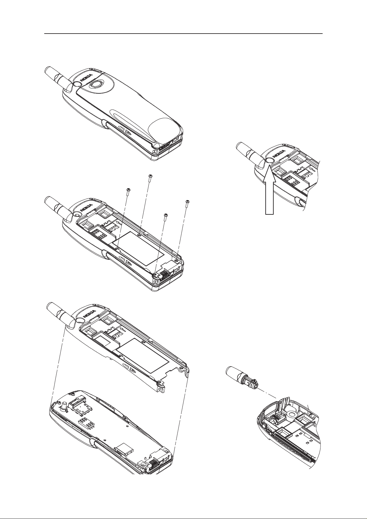
3. Remove the Screws (4x)
2. Remove Dust Cap
. Lift off B–Cover
note: snap fitting
Issue 1 07/99
5. Pull out Antenna
note: snap fitting
Page 3
Page 4

NSE–5
PAMS
Disassembly Instructions
6. Remove the Screws (2x)
Technical Documentation
8. Remove the Slide Sensor Switch
9. Pull out the Slide until the End Stop
7. Lift off the PCB
Page 4
Issue 1 07/99
Page 5

PAMS
NSE–5
Technical Documentation
10. Use a pair of Tweezers to push
the Slide Stopper Spring in the
direction indicated.
Disassembly Instructions
1 1. Simulateously with step 10:
Pull out the Slide past the
End Stop
! note: Pull out straight !
Handling the Slide Assembly:
! DO NOT handle the Slide like this ! AL WAYS handle the slide like this.
The Metal Slide is bent very easily when it is not protected by the phone.
Avoid bending of the Plungers at all times.
Issue 1 07/99
Page 5
Page 6

NSE–5
PAMS
Disassembly Instructions
12. Bend open one side of
the (plastic) Slide Cover
and take out the Metal
Slide
Technical Documentation
! DO NOT !
Hold the Metal Slide like this.
The Metal Slide is bent very easily when it is not protected by the
phone. Avoid bending of the
Plungers at all times.
ALWAYS
Handle the Metal Slide like this.
The Metal Slide can be held by the
the Plungers.
Fitting a Metal Slide onto a Slide Cover:
Push the Metal Slide onto
the snap on one side of
the Slide Cover.
Push down the other
side, but do not hit the
middle snap.
Targa Bow
Push the Metal Slide onto
the snap on the opposite
side. A click should be
noticed.
or by one of
Page 6
Issue 1 07/99
Page 7

PAMS
NSE–5
Technical Documentation
Disassembly Instructions
13. Remove the Display Assembly
14. Remove the Keymat Module
15. Remove the Speaker and the Roller Key
Issue 1 07/99
Page 7
Page 8

NSE–5
PAMS
Disassembly Instructions
16. ! Assemble the whole phone before fitting
the Slide Assembly !
The remaining assembly is done in the reverse
order of the disassembly.
17. Position the right hand Plunger onto
the start of the track and on the
Microphone Connector , as shown
Technical Documentation
Note Torque for screws 0.2Nm
18. Position the left hand Plungers onto the start of the track
and push the Slide Assembly into the phone.
! Push the Slide Assembly straight into the phone to
avoid bending of the Plungers !
Page 8
Issue 1 07/99
 Loading...