

Page 1

6800/7000 Series
Distribution and Routing Products
Installation and Operation Manual
Edition B
175-000076-00
Page 2

Page 3

6800/7000 Series
Distribution and Routing
Products
Installation and Operation Manual
Edition B
February 2003
Page 4

Page 5

Purpose
Audience
Writing Conventions
Preface
This manual details the features, installation procedures, operational
procedures, and specifications of the 6800/7000 Series - Distribution
and Routing Products.
This manual is written for technicians and operators responsible for
installation, setup, and/or operation of the 6800/7000 Series Distribution and Routing Products.
To enhance your understanding, the authors of this manual have
adhered to the following text conventions:
Bold Indicates dialog box, property sheet, field, button, checkbox,
listbox, combo box, menu, submenu, window, list, and
selection names.
Italics Indicates email addresses, names of books and publications,
and first instances of new terms and specialized words that
need emphasis.
CAPS Indicates a specific key on the keyboard, such as ENTER,
TAB, CTRL, ALT, DELETE.
Code
> Indicates direction of navigation through a hierarchy of
hyperlink
6800/7000 Series - Distribution and Routing Products Installation and Operation Manual iii
Indicates variables or command-line entries, i.e., a DOS entry,
something you type into a field, etc.
menus and windows.
Indicates a jump to another location in the document or
elsewhere (such as a website).
Page 6

Preface
Revision History
Edition Date Revision History
A May 1998 Initial release.
B February 2003
• Updated information.
• General reformatting and
reorganization of material.
iv 6800/7000 Series - Distribution and Routing Products Installation and Operation Manual
Page 7

Summary of the 6800/7000 Series
Product Manuals
Audio/Video/Mux and Demultiplexing Manual
Chapter 1 ADC-6801 CAV to SDI Converter Module
Chapter 2 ADC-6880 Analog to AES/EBU Digital Converter
Chapter 3 ADM/ASM-680x Embedded Audio Monitoring Module
Chapter 4 DAC-6801 Digital to Analog Component Converter
Chapter 5 DAC-6880 AES/EBU Digital Audio to Analog Audio
Converter
Chapter 6 DEC-6801/DES-6801 Decoder/Decoder with Frame
Synchronizer Module
Chapter 7 DEC-6804 Decoder and DES-6804 Decoder with Frame
Synchronizer
Chapter 8 ENC-ENS/ENX-6801A Encoder Modules
Preface
Chapter 9 MXA-6800-AES and MXA-6801-A2/A4 Audio Multiplexer
Module
Chapter10 VFS-6801 Serial Component Frame Synchronizer Module
Chapter 11 VTS-6801 Video Timing Switcher
Appendix A Embedding Modes Graphic Description
Test Series Manual
Chapter 1 VTG-6801-1 &VTG-6801-1A 4:2:0 & 4:2:2 Serial Digital
Test Generator Module
Chapter 2 VTG-6801-2 Serial Digital Test Generator Module
Chapter 3 DAR-6880 AES/EBU Digital Audio Reference and Tone
Generator
Chapter 4 SAI-6800 4:2:2 Safe Area Generator/Inserter Module
Chapter 5 VTG-6800 MIXBOX Frame and Control Assembly
Chapter 6 EDH-6800MB Detection and Handling MIXBOX
6800/7000 Series - Distribution and Routing Products Installation and Operation Manual v
Page 8

Preface
Distribution and Routing Manual
Chapter 1 AES-6880 AES/EBU Digital Audio Distribution Amplifier
Module - General
Chapter 2 DNH-6800 DigiNet Hub Module
Chapter 3 EDH-6800-2EDH Detection/Insertion Serial Distribution
Amplifier Module
Chapter 4 USM-6800 PAL/NTSC Monitoring Encoder Module
Chapter 5 VDA-6830 Video Distribution Amplifier Module
Chapter 6 VEA-6830 Video Equalizing Amplifier Module
Chapter 7 VEA-6840 Video Equalizing Amplifier Module
Chapter 8 VPD-6830 Programmable Video DA series
Chapter 9 VSD-6801 Serial Digital Distribution Amplifier Module
Chapter 10 VSE-6801 Serial Equalizing Amplifier Module
Chapter 11 VSE-6802 Serial Equalizing Distribution Amplifier
Chapter 12 VSM-6802 Digital Composite Video Signal
Chapter 13 VSM-6804 Digital Composite Video Signal Monitor
Module
Chapter 14 VSR-4041 Serial Video Router Module
LogoMotion Manual
Chapter 1 Logo Utilities for 6800 Series Modules
Chapter 2 LGI-6801 Serial Digital Logo Generator/Inserter Module
Chapter 3 VES-6801 Flash EPROM Side Module
Chapter 4 DSK-6801/3 Downstream Serial Keyer
Chapter 5 DSK-CP1/2 Downstream Serial Keyer Control Panel
vi 6800/7000 Series - Distribution and Routing Products Installation and Operation Manual
Page 9

Frames and Power Supply Manual
Chapter 1 Mounting Frames
Chapter 2 FR-6801/FR-6801-1 Frames
Chapter 3 FR-6804/FR-6804-1 Frames
Chapter 4 CF-6801 Cooling Frame
Chapter 5 FR-7001 and FR-7000MB MIXBOX
Chapter 6 6801PS Power Supply Module
Chapter 7 6804(-1) Power Supply Module
Chapter 8 7000 Power Supply Module
Chapter 9 6801PS-48 Power Supply Module
Chapter 10 6804PS-1-48 Power Supply Module
Preface
6800/7000 Series - Distribution and Routing Products Installation and Operation Manual vii
Page 10

Unpacking/Shipping Information
This product has been carefully inspected, tested and calibrated before
shipment to ensure years of stable and troublefree service. Please check
the equipment for any visible damage which may have occurred during
transit.
Please confirm that all items listed on the packing list have been
received. If any item on the packing list is missing, please contact your
Leitch dealer. If any item is damaged please contact the carrier. Ensure
that all packaging material is removed from the product and its
associated components before installing the unit.
It is suggested that you keep at least one set of original Leitch packaging,
in the event that a product needs to be returned for service. If the
original packaging is not available, you can purchase replacement
packaging from Leitch at a modest cost or supply your own packaging as
long as it meets the following criteria:
• Packaging must be able to withstand the product weight.
• Product must be held rigid within the packaging.
• There must be at least two inches of space between the product
and the container.
Preface
• The corners of the product must be protected.
Products that are being returned to Leitch for servicing should be
shipped pre-paid in the original packaging material if possible. If the
product is still within the warranty period, the product will be returned
by pre-paid shipment after servicing.
Installation Information
If this product is rack mountable, it should be mounted in an
appropriate rack using the rack mounting positions and rear support
guides provided. It is recommended that each frame be connected to a
separate electrical circuit for protection against circuit overloading. If
this product relies on forced air cooling, it is recommended that all
obstructions to the air flow be removed prior to installing the frame in
the rack.
If this product has a provision for external earth grounding, it is
recommended that the frame be grounded to earth via the protective
earth ground on the rear panel.
6800/7000 Series - Distribution and Routing Products Installation and Operation Manual vii
Page 11
Preface
Important Safety Instructions
Review the following safety precautions to avoid injury and prevent
damage to this product or any products connected to it. Read these
instructions. Keep these instructions. Heed all warnings. Follow all
instructions.
Servicing
Only qualified personnel should perform service procedures. Refer all
servicing to qualified service personnel. Servicing is required when the
apparatus has been damaged in any way, such as power-supply cord or
plug is damaged, liquid has been spilled or objects have fallen into the
apparatus, the apparatus has been exposed to rain or moisture, does not
operate normally, or has been dropped.
Safety Terms and Symbols
Terms and Symbols in This Manual
WARNING:
Statements identifying conditions or practices that can result in
personal injury or loss of life: High voltage is present. Uninsulated
dangerous voltage within the product’s enclosure may be sufficient
to constitute a risk of electric shock to persons.
CAUTION:
Statements identifying conditions or practices that can result in
damage to the equipment or other property: Important operating
and maintenance (servicing) instructions in the literature
accompanying the product.
Terms and Symbols on the Product
DANGER:
High voltage and indicates a personal injury hazard immediately
viii 6800/7000 Series - Distribution and Routing Products Installation and Operation Manual
accessible as one reads the marking.
WARNING:
Indicates a personal injury hazard not immediately accessible as
one reads the marking.
CAUTION:
Indicates a hazard to property including the product or to take
attention and refer to the manual.
Page 12
Injury Precautions
Preface
Protective ground (earth) terminal.
Fuse:
Replace with same type and rating of fuse.
Observe precautions for handling electrostatic-sensitive devices.
WARNING!
To reduce the risk of electric shock, do not expose this apparatus to
rain or moisture.
CAUTION
RISK OF ELECTRIC SHO CK
DO NOT OPEN
WARNING!
Potentially lethal voltages are present within this product’s frame
during normal operation. The AC power cord must be
disconnected from the frame before the top panel is removed. (In
frames with multiple power supplies, remove ALL power cords.)
Power should not be applied to the frame while the top is open,
unless properly trained personnel are servicing the unit.
[PL Poland] Przod zdjeciem pokrywy wyciagnac wtyczke z gniazda
sieciowego.
[French] AVIS: RISQUE DE CHOC ELECTRIQUE - NE PAS
OUVRIR. INSTALLER SUR SUPPORT DE MONTAGE
SEULEMENT.
6800/7000 Series - Distribution and Routing Products Installation and Operation Manual ix
Page 13
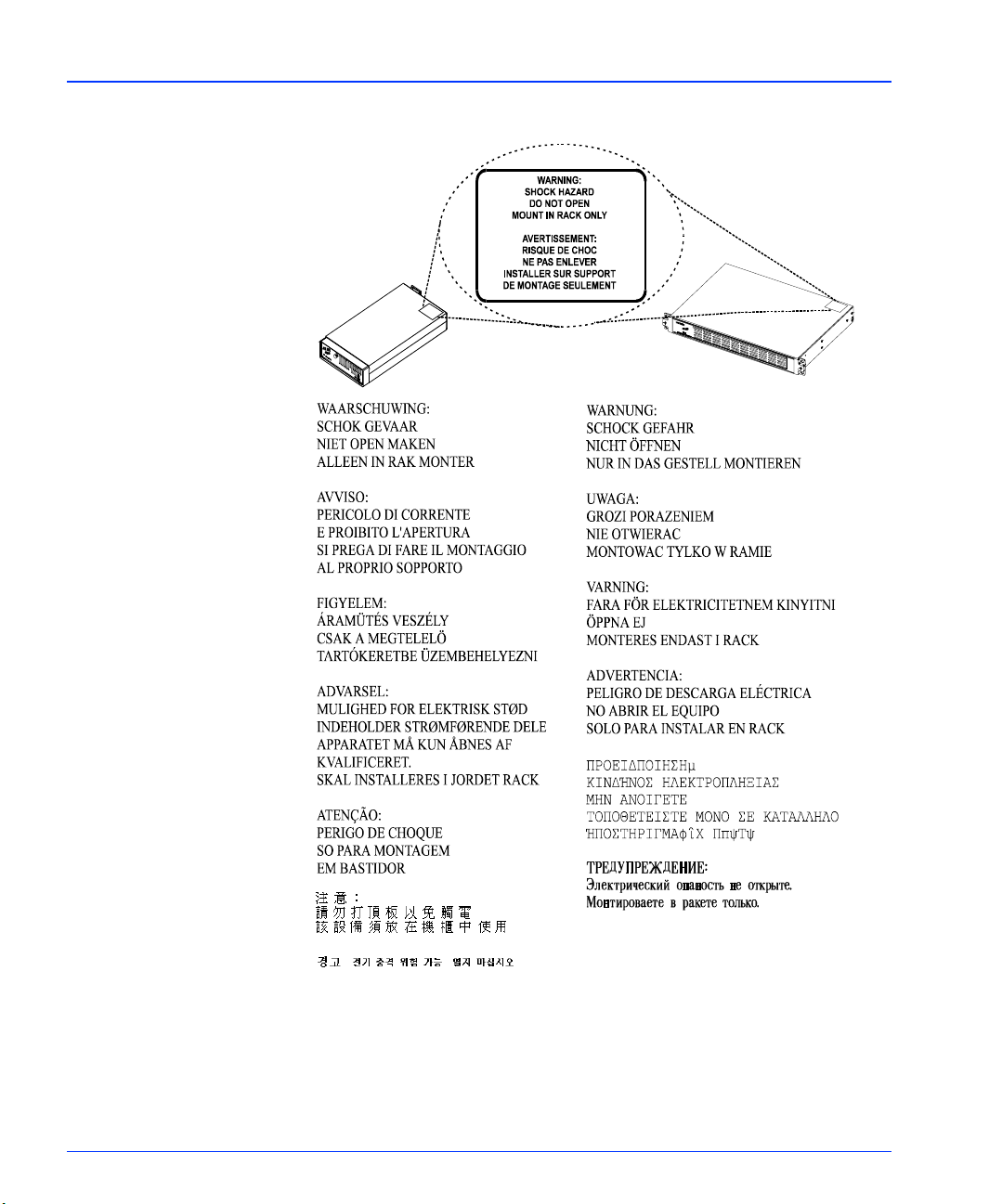
Preface
AVIS - Risque de choc electrique. Ne pas
ouvrir.
x 6800/7000 Series - Distribution and Routing Products Installation and Operation Manual
Page 14
Preface
Use Proper Power Cord
To avoid fire hazard, use only the power cord specified for this
product.
Ground the Product
Do not defeat the safety purpose of the polarized or grounding-type
plug. A polarized plug has two blades with one wider than the other.
A grounding type plug has two blades and a third grounding prong.
The wide blade or the third prong are provided for your safety.
When the provided plug does not fit into your outlet, consult an
electrician for replacement of the obsolete outlet.
[United Kingdom] WARNING: THIS APPLIANCE MUST BE
EARTHED.
[Sweden] APPARATEN SKALL ANSLUTAS TILL JORDAT
UTTAG NÄR DEN ANSLUTS TILL ETT NÄTVERK.
Do Not Operate Without Covers
To avoid electrical shock or fire hazard, do not operate this product
with covers or panels removed.
Use Proper Fuse
To avoid fire hazard, use only the fuse type and rating specified for
this product.
Do Not Operate in Wet/Damp Conditions
To reduce the risk of fire or electric shock, do not expose this
apparatus to rain or moisture
Do Not Operate in an Explosive Atmosphere
To avoid injury or fire hazard, do not operate this product in an
explosive atmosphere.
Avoid Exposed Circuitry
To avoid injury, remove jewelry such as rings, watches, and other
metallic objects. Do not touch exposed connections and
components when power is present.
6800/7000 Series - Distribution and Routing Products Installation and Operation Manual xi
Page 15
Preface
Product Damage Precautions
Use Proper Power Source
Do not operate this product from a power source that supplies
more than the specified voltage.
Use Proper Voltage Setting
Before applying power, ensure that the line selector is in the proper
position for the power source being used.
Provide Proper Ventilation
To prevent product overheating, provide proper ventilation.
Do Not Block Any Ventilation Openings
Do not block any of the ventilation openings. Install in accordance
with the manufacturer’s instructions.
Only Use Attachments/Accessories Specified by the Manufacturer
Do Not Operate With Suspected Failures
Refer all servicing to qualified service personnel. Servicing is
required when the apparatus has been damaged in any way, such as
power-supply cord or plug is damaged, liquid has been spilled or
objects have fallen into the apparatus, the apparatus has been
exposed to rain or moisture, does not operate normally, or has been
dropped.
For Products with Multiple Power Cords:
CAUTION: This unit can have more than one power supply cord.
To de-energize the internal circuitry, disconnect all power cords
before servicing.
[Norwegian] ADVARSEL: Utstyret kan ha mere ennn en
tilførselsledning. For å gjore interne deler spennigsløse må alle
tilførselsledningene trekkes ut.
[Sweden] VARNING: Denna apparat har mer än en nätanslutning.
Samtliga nätkablar måste bortkopplas för att göra de interna
kretsarna spänningsfria.
xii 6800/7000 Series - Distribution and Routing Products Installation and Operation Manual
Page 16
Preface
Do not use this apparatus near water
Do not expose this apparatus to dripping or splashing water.
Ensure that no objects filled with liquid, such as vases or cups, are
placed on the apparatus.
Clean only with a dry cloth
Keep Product Away from Heat Sources
Do not install near any heat sources such as radiators, heat registers,
stoves, or other apparatus (including amplifiers) that produce heat.
Install Near Socket Outlet
The equipment shall be installed near the socket outlet, and a
disconnect device shall be easily accessible.
Protect the Power Cord
Protect the power cord from being walked on or pinched
particularly at plugs, convenience receptacles, and the point where
they exit from the apparatus.
Unplug this Apparatus During Lightning Storms
Unplug this apparatus during lightning storms or when unused for
long periods of time. Note: A UPS or power surge suppressor could
be used as an alternative.
Attention:
Observe precautions for handling electrostatic-sensitive devices.See
“Preventing Electrostatic Discharge” below for details.
Fuse Replacement:
CAUTION: FOR CONTINUED PROTECTION AGAINST RISK
OF FIRE, REPLACE ONLY WITH THE SAME TYPE OF FUSE.
[French]ATTENTION: REMPLACER UNIQUEMENT PAR UN
FUSIBLE DE MEME TYPE.
6800/7000 Series - Distribution and Routing Products Installation and Operation Manual xiii
Page 17
Preface
Battery Use Warnings
CAUTION:
DANGER OF EXPLOSION IF BATTERY IS INCORRECTLY
PLACED. REPLACE ONLY WITH THE SAME OR
EQUIVALENT TYPE RECOMMENDED BY THE
MANUFACTURER. DISCARD USED BATTERIES ACCORDING
TO THE MANUFACTURER’S INSTRUCTIONS.
[FI Finland] VAROITUS: Paristo voi rajahtaa, jos se on
virheellisesti asennettu. Vaihda paristo ainoastaan valmistajan
suosittelemaan tyyppun. Havita kaytetty paristo valmistajan
ohjeiden mukaisesti.
[SE Sweden] VARNING: Explosionsfara vid felaktigt batteribyte.
Anvand samma batterityp eller en eller en ekvivalent typ som
rekommenderas av tillverkaren. Kassera anvant batteri enligt
fabrikantens instruktion.
[D Denmark]
Advarsel! Lithiumbatteri. Eksplosionsfare ved
fejlagtig handtering. Udskift ning ma kun ske med
batteri af samme fabrikat oq type. Lever det
brugte batteri tilbage till leverandoren.
[KO Korean]
xiv 6800/7000 Series - Distribution and Routing Products Installation and Operation Manual
Page 18

Preventing Electrostatic Discharge
Preface
CAUTION: Electrostatic discharge (ESD) can damage components
in the product. To prevent ESD, observe these precautions when
directed to do so:
• Use a Ground Strap. Wear a grounded antistatic wrist strap to
discharge the static voltage from your body while installing or
removing sensitive components.
• Use a Safe Work Area. Do not use any devices capable of
generating or holding a static charge in the work area where you
install or remove sensitive components. Avoid handling sensitive
components in areas that have a floor or benchtop surface capable
of generating a static charge.
• Handle Components Carefully. Do not slide sensitive
components over any surface. Do not touch exposed connector
pins. Handle sensitive components as little as possible.
• Transport and Store Carefully. Transport and store sensitive
components in a static-protected bag or container.
6800/7000 Series - Distribution and Routing Products Installation and Operation Manual xv
Page 19

Preface
Certifications and Compliances
This product has been tested and found to comply with the following
CE, FCC, UL, ICES and CSA standards:
EMC Standards
EN55014 Limits and methods of measurement of radio disturbance
characteristics of electric motor-operated and thermal
appliances for household and similar purposes, electric
tools and similar electric apparatus.
EN55022 Limits and methods of measurement of radio disturbance
characteristics of information technology equipment Class
A.
EN55103-1 Electromagnetic compatibility—Product family standard
for audio, video, audio-visual and entertainment lighting
control apparatus for professional use, Part 1: Emission,
Environment E4.
EN55103-2 Electromagnetic compatibility—Product family standard
for audio, video, audio-visual and entertainment lighting
control apparatus for professional use, Part 2: Emission,
Environment E4.
EN61000-4-2 Electrostatic discharge requirements “ESD” 2kV CD,4kV
AD.
EN61000-4-3 Radiated radio-frequency electromagnetic field immunity
test 1V/m {1kHz 80% AM, 80-1000MHz}.
EN61000-4-4 Electrical Fast transient requirements “Burst”, 0.5kV Sig. &
Ctrl. Lines 0.5kV a.c. & d.c. Power line, 0.5kV functional
earth.
EN61000-4-5 Surge Immunity test 0.5kV a.c. Power line.
EN61000-4-6 Immunity to conducted disturbances induced by radio
frequency fields 1V rms 0.15-80MHz Sig. & Ctrl. Lines, 3V
rms 0.15-80MHz d.c. Power line, 1V rms 0.15-80MHz a.c.
Power line, 1V rms 0.15-80MHz functional earth.
EN61000-4-11 Voltage dips, short interruptions and voltage variations-
immunity tests.
xvi 6800/7000 Series - Distribution and Routing Products Installation and Operation Manual
Page 20

Safety Standards
Preface
per the provision of the Electromagnetic Compatibility Directive 89/
336/EEC of 3 May 1989 as amended by 92/31EEC of 28 April 1992 and
93/68/EEC, Article 5 of 22 July 1993.
These devices are for professional use only and comply with Part 15 of
FCC rules. Operation is subject to the following two conditions:
1. These devices may cause interference to Radio and TV receivers in
residential areas
2. These devices will accept any interference received, including
interference that may cause undesired operations.
These devices do not exceed the class A limits for radio noise emissions
from digital apparatus as set out in the interference standard entitled
“Digital apparatus”, ICES-003 of the Canadian Department of
Communications.
EN60065 Safety requirements for mains operated electronic and
related apparatus for household and similar general use
[IEC 60065: 1985, 5th Edition + A1: 1987 + A2: 1989 + A3:
1992, (modified)], per the provision of the Low-Voltage
Directive 73/23/EEC of February 19, 1973, as amended by
93/68/EEC.
UL 1419
CSA C22.2
No. 1
Safety requirements for audio, video and similar electronic
equipment.
Safety Standards (6801PS-48) Only
EN 60950-1992 Safety of information technology equipment, including
electrical business equipment (Amendments A1: 1993, A2:
1993, A3: 1995, A4: 1997), per the provision of the LowVoltage Directive 73/23/EEC of February 19, 1973 as
amended by 93/68/EEC.
UL 1950 Safety of information technology equipment, including
electrical business equipment.
CSA C22.2
No.95095
6800/7000 Series - Distribution and Routing Products Installation and Operation Manual xvii
Safety of information technology equipment, including
electrical business equipment.
Page 21

Preface
Safety Standards: (6801PS-1-48) Only
EN 60950-2000 Safety of information technology equipment, including
UL 1950 Safety of information technology equipment, including
electrical business equipment (IEC-60950:1999), per the
provision of the Low-Voltage Directive 73/23/EEC of
February 19, 1973 as amended by 93/68/EEC.
electrical business equipment.
CSA C22.2
No.950
Safety of information technology equipment, including
electrical business equipment.
xviii 6800/7000 Series - Distribution and Routing Products Installation and Operation Manual
Page 22

Contents
Chapter 1: AES-6880 AES/EBU
Digital Audio Distribution Amplifier Module ..............1
Overview .....................................................................................................1
Board Layout and Functionality ................................................................ 2
Functional Block Diagram ..................................................................2
Equalization Adjustment ............................................................................3
Manual Equalization ...........................................................................3
Automatic Equalization ...................................................................... 3
Error Detection and Reporting ..................................................................5
User Configurable Contact Closure Alarm Indicator ........................6
External Alarm .................................................................................... 7
Specifications .............................................................................................. 8
Inputs ................................................................................................... 8
Output ................................................................................................. 8
Power Supply .......................................................................................9
Chapter 2: DNH-6800 DigiNet Hub Module ...............11
Overview ...................................................................................................11
Block Diagram Flow .......................................................................... 12
Specifications ............................................................................................ 13
Total Power Dissipation .................................................................... 13
DigiNet Ports ..................................................................................... 13
Maximum Unit Nodes ...................................................................... 14
Installation ................................................................................................ 15
Mounting Requirements ...................................................................15
Cooling .............................................................................................. 15
Connections .............................................................................................. 16
6800/7000 Series - Distribution and Routing Products Installation and Operation Manual xxi
Page 23

Contents
Network Configurations .......................................................................... 17
Small Network ................................................................................... 17
Mid-Size Network ............................................................................. 18
Large Network ................................................................................... 19
User Interface ........................................................................................... 20
Indicators and Controls .................................................................... 20
Chapter 3: EDH-6800-2 EDH Detection/Insertion Serial
Distribution Amplifier Module..................................... 23
Overview ................................................................................................... 23
Specifications ............................................................................................ 24
Serial Video Input ............................................................................. 24
Serial Video Outputs ......................................................................... 24
Control Interface ............................................................................... 25
Power ................................................................................................. 25
Installation ................................................................................................ 26
Functional Block Diagram ................................................................ 26
Controls, Indicators, and Jumpers ........................................................... 27
Switches ............................................................................................. 27
LEDs .................................................................................................. 28
Jumpers ............................................................................................. 30
Fault Reporting Output ............................................................................ 32
Chapter 4: USM-6800 PAL/NTSC Monitoring
Encoder Module............................................................. 33
Overview ................................................................................................... 33
Features ..................................................................................................... 34
Specifications ............................................................................................ 35
Serial Video Input ............................................................................. 35
Serial Video Outputs ......................................................................... 35
Composite Analog Outputs .............................................................. 36
Component Analog Outputs ............................................................ 36
Functional Block Diagram ................................................................ 37
Rear Connector ................................................................................. 37
Controls and Indicators ........................................................................... 38
Status LEDs ....................................................................................... 38
Default Settings ................................................................................. 38
User Interface ........................................................................................... 39
Converting from Component YUV to Four Composite Outputs ... 41
xxii 6800/7000 Series - Distribution and Routing Products Installation and Operation Manual
Page 24

Contents
Chapter 5: VDA-6830 Video Distribution
Amplifier Module ...........................................................43
Overview ...................................................................................................43
Specifications ............................................................................................ 44
Input .................................................................................................. 44
Output ............................................................................................... 44
Performance ...................................................................................... 45
Temperature ...................................................................................... 45
Installation ................................................................................................ 46
Operational Adjustments ......................................................................... 46
Chapter 6: VEA-6830 Video
Distribution Amplifier Module.....................................47
Overview ...................................................................................................47
Specifications ............................................................................................ 49
Input .................................................................................................. 49
Output ............................................................................................... 49
Performance ...................................................................................... 50
Differential Gain ............................................................................... 50
Temperature ...................................................................................... 50
Installation ................................................................................................ 51
Operation .................................................................................................. 52
Chapter 7: VEA-6840 Video
Equalizing Amplifier Module .......................................53
Overview ...................................................................................................53
Modules .................................................................................................... 55
Specifications ............................................................................................ 57
Input .................................................................................................. 57
Output ............................................................................................... 57
Performance ...................................................................................... 58
Equalization ....................................................................................... 58
Clamp ................................................................................................ 59
Temperature ...................................................................................... 59
Power Requirements ......................................................................... 59
Installation ................................................................................................ 60
Removing and Installing the RMV Submodule ............................... 60
Configuration ........................................................................................... 61
Input Coupling .................................................................................. 61
Clamp Mode ...................................................................................... 61
Operation .................................................................................................. 62
6800/7000 Series - Distribution and Routing Products Installation and Operation Manual xxiii
Page 25

Contents
Chapter 8: VPD-6830 Programmable
Video DA Series ............................................................. 63
Overview ................................................................................................... 63
VPD-6830 Series DAs ............................................................................... 64
Cables ................................................................................................ 64
Installation ................................................................................................ 65
VPD-6830-CLP ................................................................................. 65
VPD-6830-CLP Specifications ................................................................. 67
Input .................................................................................................. 67
Output ............................................................................................... 67
Performance ...................................................................................... 67
Clamp ................................................................................................ 69
Temperature ...................................................................................... 69
Power Requirements ......................................................................... 69
VPD-6830-CLP ......................................................................................... 70
Configuration .................................................................................... 70
VPD-6830-XEQ ........................................................................................ 72
VPD-6830-XEQ Specifications ................................................................ 73
Input .................................................................................................. 73
Output ............................................................................................... 73
Performance ...................................................................................... 73
Clamp ................................................................................................ 74
Temperature ...................................................................................... 74
Power Requirements ......................................................................... 74
VPD-6830-XEQ ........................................................................................ 75
Configuration .................................................................................... 75
VPD-6830-DEQ ....................................................................................... 77
VPD-6830-DEQ Specifications ................................................................ 78
Input .................................................................................................. 78
Output ............................................................................................... 78
Performance ...................................................................................... 79
Clamp ................................................................................................ 79
Temperature ...................................................................................... 79
Power Requirements ......................................................................... 80
VPD-6830-DEQ ....................................................................................... 81
Configuration .................................................................................... 81
VPD-6830-DLY Series .............................................................................. 83
xxiv 6800/7000 Series - Distribution and Routing Products Installation and Operation Manual
Page 26

Contents
VPD-6830 DLY Specifications ................................................................. 85
Input .................................................................................................. 85
Output ............................................................................................... 85
Performance ...................................................................................... 85
Clamp ................................................................................................ 87
Temperature ...................................................................................... 87
Power Requirements ......................................................................... 87
VPD-6830-DLY240 .................................................................................. 88
Configuration .................................................................................... 88
VPD-6830-DLY Series .............................................................................. 90
Configurations .................................................................................. 90
Chapter 9: VSE-6801 Serial Equalizing
Amplifier Module ...........................................................93
Specifications ............................................................................................ 93
Serial Video Input .............................................................................93
Serial Video Outputs ......................................................................... 94
Operation .................................................................................................. 95
Jumpers .............................................................................................. 95
LED Indicators ................................................................................. 95
Chapter 10: VSE-6802 Serial Equalizing Distribution
Amplifier Module............................................................97
Overview ...................................................................................................97
Specification .............................................................................................. 99
Operation .......................................................................................... 99
LED Indicators ................................................................................ 100
Jumper and Potentiometer ............................................................. 101
Chapter 11: VSD-6801 Serial
Digital Distribution Amplifier Module..................... 103
Specifications .......................................................................................... 103
Serial Video Input ...........................................................................103
Serial Video Outputs ....................................................................... 104
6800/7000 Series - Distribution and Routing Products Installation and Operation Manual xxv
Page 27

Contents
Chapter 12: VSM-6802 Digital Composite
Video Signal Monitor Module....................................105
Overview ................................................................................................. 105
Specifications .......................................................................................... 106
Video ............................................................................................... 106
Serial Outputs .................................................................................. 106
Analog Output (NTSC or PAL) ...................................................... 106
Installation .............................................................................................. 108
Operation ........................................................................................ 108
Chapter 13: VSM-6804 Digital Composite
Video Signal Monitor Module....................................109
Overview ................................................................................................. 109
Specifications .......................................................................................... 110
Serial Input ...................................................................................... 110
Serial Outputs .................................................................................. 110
Composite Analog Output .............................................................. 111
Installation .............................................................................................. 112
Operation ........................................................................................ 112
LED Indicators ................................................................................ 113
Interface Switches ........................................................................... 113
Chapter 14: VSR-4041 Serial
Video Router Module..................................................115
Specifications .......................................................................................... 115
Video Input ..................................................................................... 115
Operating Standards ....................................................................... 115
Switching Point ............................................................................... 116
Installation .............................................................................................. 117
Selecting a Bus ................................................................................. 117
Selecting an Operating Standard .................................................... 117
Selecting V-trig (J10) ...................................................................... 118
Selecting Single/Dual Bus (J11) ...................................................... 118
Connection ...................................................................................... 118
Adjustment ............................................................................................. 119
Test Points ....................................................................................... 120
Control Panel .......................................................................................... 121
xxvi 6800/7000 Series - Distribution and Routing Products Installation and Operation Manual
Page 28

Overview
Chapter 1
AES-6880 AES/EBU
Digital Audio Distribution
Amplifier Module
The AES-6880 is a differential input, eight output; AES/EBU digital
audio distribution amplifier. Using Coaxial Cable, The AES-6880 digital
audio distribution amplifier features cable auto-equalization, data
reclocking, and incoming data error detection and reporting.The error
detection and reporting features utilize front-mounted LEDs and an
external alarm contact closure.
Housed in either an FR-6800 or FR-7000 series frame, the AES-6880
meets interface standards according to SMPTE 276M.
Specifications and designs are subject to change without notice.
6800/7000 Series - Distribution and Routing Products Installation and Operation Manual 1
Page 29
Chapter 1: AES-6880 AES/EBU Digital Audio Distribution Amplifier Module Board Layout and Functionality
A
Board Layout and Functionality
The following diagrams show the layout and functionality of the
AES-6880 board.
Figure 1-1. AES-6880 Printed Circuit Board
Functional Block Diagram
AES
W
75
Coax
Input
EQ
Mode
Select
Manual Auto
Manual
EQ Adjust
Cable
EQ
Auto
EQ
ALL OK
No Lock
Bi-Phase Coding
Parity
CRC
Confidence Flag
Val idi ty
ALARM
Reclocked
Reconstruction
External
Alarm
Configure
ES
W
75
Coax
Outputs
(x8)
External Alarm
Contact Closure
Figure 1-2. AES-6880 Functional Block Diagram
2 6800/7000 Series - Distribution and Routing Products Installation and Operation Manual
Page 30

Equalization Adjustment Chapter 1: AES-6880 AES/EBU Digital Audio Distribution Amplifier Module
Equalization Adjustment
The AES-6880 distribution amplifier provides two options for
equalization adjustment: Manual and Aut omatic . The mode is selected
using jumper J1 near the front edge of the DA card. See Figure 1-3 on
page 4 for jumper location.
Manual Equalization
In Manual adjust mode, a card-edge, multi-turn potentiometer (R19) is
used for adjusting equalization. The Confidence flag warning on the
card-edge LED is used to determine the amount of equalization required
without external test equipment. If the Confidence flag error LED is on,
then more equalization is needed.
To increase the amount of equalization, simply use a screwdriver to turn
the Manual equalization adjustment potentiometer (R19) clockwise until
the Confidence LED indicator turns off. See Figure 1-3 on page 4 for
potentiometer location.
Automatic Equalization
In Aut omatic adjust mode, the distribution amplifier automatically sets
the amount of cable equalization needed. This mode eliminates the need
The factory default
configurations for J1 is in the
“Aut o” position, and the
Manual equalization
adjustment potentiometer
(R19) is set for zero
compensation.
6800/7000 Series - Distribution and Routing Products Installation and Operation Manual 3
to re-adjust equalization if another distribution amplifier is installed or
exchanged, or if the cable length changes.
The equalization is designed for using 2000 ft (600 m) of Belden 8281
cable or the equivalent. In practice, if the incoming signal is a standard
AES signal for coaxial cable systems, this DA can compensate up to 6000
ft (1800 m) of Belden 8281 cable or equivalent.
Page 31

Chapter 1: AES-6880 AES/EBU Digital Audio Distribution Amplifier Module Equalization Adjustment
A
uto
EQ
J1
Manual
EQ Adjust
All OK
No Lock
Bi-Phase Code Red LED
Parity
CRC
Confidence Red LED
Val idi ty
Alarm
R19
Green LED
Red LED
Red LED
Red LED
Red LED
Red LED
Multi-turn potentiometer
used to adjust equalization.
(Manual EQ Mode Only)
Figure 1-3. AES-6880 Card-Edge View
Manual
EQ
4 6800/7000 Series - Distribution and Routing Products Installation and Operation Manual
Page 32

Error Detection and Reporting Chapter 1: AES-6880 AES/EBU Digital Audio Distribution Amplifier Module
Error Detection and Reporting
The AES-6880 DA constantly monitors the incoming AES data stream
and reports the following error conditions via the LED indicators
mounted near the card’s front edge. LED indicators and conditions are
described in the following table:
Condition Indicator Description Of Condition
All OK;
No Errors
No Lock Red LED Signal is not present or cannot be locked.
Biphase Coding
Error
Parity Error Red LED SRD stream’s parity bit is not set as
CRC Error Red LED The CRC value calculated for the
Confidence Flag
Error
Validity Error Red LED AES stream’s validity bit is high.
Green LED No errors detected.
Red LED Biphase coding of incoming date is
incorrect.
specified.
incoming data does not match the CRC
byte of the channel status word.
Red LED The received data eye opening is less
than a half-bit period, indicating a
possible lack of signal strength or high
jitter.
May also indicate that insufficient EA is
applied.
The incoming data is not suitable for
conversion to an analog audio signal.
Alarm Red LED Indication that the external alarm
contact closure is asserted, and this card
is reporting an alarm.
6800/7000 Series - Distribution and Routing Products Installation and Operation Manual 5
Page 33

Chapter 1: AES-6880 AES/EBU Digital Audio Distribution Amplifier Module Error Detection and Reporting
A
A
User Configurable Contact Closure Alarm Indicator
A red LED mounted under the Error LEDs on the front edge of the DA
card provides a user-configurable Contact Closure alarm indicator.
When this LED is on, the external alarm contact closure is asserted,
indicating an error has occurred.
Jumpe rs J3A-F are used to determine which error conditions will trigger
the alarm (see Figure 1-4 below). When all of the jumpers are in place,
any of the condition errors will trigger the Contact Closure alarm to be
asserted. If one of these jumpers is removed, then the error condition
associated with the missing jumper may occur but will not trigger the
Contact Closure alarm to be asserted and the Alarm LED will not light.
Whenever the contact closure alarm is asserted, the Alarm LED will light
and an alarm Contact Closure signal will be sent out.
AUTO
EQ SELECT
MANUAL
MANUAL
EQ ADJUST
BIPHASE CODE
ALL OK
NO LOCK
PARIT Y
CONFIDENCE
VALID ITY
ALARM
External Alarm Configure
J3A Validity
J3B Confidence
J3C CRC
J3D Parity
J3E Biphase Code
J3
B
C
D
E
F
J3F No Lock
EXTERNAL ALARM CONFIGURE
J3A VALI DITY
J3B CONFIDENCE
J3C CRC
J3D PARITY
J3E BIPHASE CODE
J3F NO LOCK
CRC
AES-6880
J3
B
C
D
E
F
Figure 1-4. AES-6880 Jumper Selection
6 6800/7000 Series - Distribution and Routing Products Installation and Operation Manual
Page 34

Error Detection and Reporting Chapter 1: AES-6880 AES/EBU Digital Audio Distribution Amplifier Module
External Alarm
An external alarm may be connected to an FR-6800 or FR-7000 series
frame housing this and other DAs. The alarm is shared by all the DA
modules housed within the frame. If a card within the frame detects and
triggers the Contact Closure alarm, the external alarm is asserted.
Figure 1-5 below shows how a typical alarm configuration looks within a
system.
Figure 1-5. External Alarm Connections
6800/7000 Series - Distribution and Routing Products Installation and Operation Manual 7
Page 35

Chapter 1: AES-6880 AES/EBU Digital Audio Distribution Amplifier Module Specifications
Specifications
Inputs
Item Specification
Number of Inputs 1
Input Coupling Transformer Coupling
Output
Input Impedance 75
Input Return Loss >30 dB
Normal Input Signal
Level
Minimum Input
Signal Level
W
1.0 Vp-p
0.1 Vp-p
Item Specification
Number of Outputs 8
Output Impedance 75
Output Return Loss 30 dB
Level 1.0 Vp-p
DC Offset <50 mV
EQ 2
EQ Mode Automatic or manual adjustment
Reclock Yes
W
000 ft (600 m) Belden 8281 cable or equivalent
Output Jitter <5 ns
Rise and Fall Time Between 35 ns and 42 ns
Propagation Delay Approximately 600 ns
8 6800/7000 Series - Distribution and Routing Products Installation and Operation Manual
Page 36

Specifications Chapter 1: AES-6880 AES/EBU Digital Audio Distribution Amplifier Module
Power Supply
The power supply equipped in either an FR-6800 or FR-7000 series
frame is appropriate for the AES-6880. The power supply supplies
±6.5 V to the module.
6800/7000 Series - Distribution and Routing Products Installation and Operation Manual 9
Page 37

Chapter 1: AES-6880 AES/EBU Digital Audio Distribution Amplifier Module Specifications
10 6800/7000 Series - Distribution and Routing Products Installation and Operation Manual
Page 38

DNH-6800 DigiNet Hub Module
Overview
Chapter 2
The DNH-6800 DigiNet Hub module connects up to nine separate
DigiNet cable segments into one logical control network, making it
possible to span large physical distances and support a greater number
of unit nodes without degradation of signal quality due to attenuation
and return loss.
A data stream originating from a node on any one of the nine DigiNet
segments is automatically detected, reclocked, reshaped, and
retransmitted to all other segments by the DNH-6800. DigiNet’s Carrier
Sense Multiple Access with Collision Detect (CSMA/CD) protocol is
supported by implementing independent collision detection on each
channel and by a jamming mechanism that propagates a collision event
detected on a transmitting channel to transmitting nodes on all other
channels (see Figure 2-1 “DNH-6800 Block Diagram Flow” on page 12).
Specifications and designs are subject to change without notice.
6800/7000 Series - Distribution and Routing Products Installation and Opertion Manual 11
Page 39

Chapter 2: DNH-6800 DigiNet Hub Module Overview
Block Diagram Flow
Port
0
1
2
3
4
5
6
7
8
Coax
Tra nc eiv ers
Collision
Detection
Channel
Arbitration
Reclocking
Figure 2-1. DNH-6800 Block Diagram Flow
LED
Driver
User
Interface
LEDs
12 6800/7000 Series - Distribution and Routing Products Installation and Opertion Manual
Page 40

Specifications Chapter 2: DNH-6800 DigiNet Hub Module
Specifications
Total Power Dissipation
Item Specification
Maximum (heavy traffic) 250 mA @ 6.5V
(positive rail 1.50 W, negative rail 0.3 W,
total 1.8 W)
Minimum (no traffic) 75 mA @ -6.5V
DigiNet Ports
Item Specification
Number 1 (named Channel 0)
Type 75
Location Auxiliary input B
Number 8 (named Channel 1 through Channel 8)
Type 75
Location Backplane connector, Outputs 1 through 8
Network Protocol LonTalk CSMA/CD with proprietary
Signaling 1.25 Mb/s, Manchester encoded
Levels 1 V
Return Loss Channel 0:
W BNC connector, unterminated
W BNC connector (with on-board
termination)
transceiver
• 28 dB or better @ 2.5 MHz
• 22 dB or better @ 5.0 MHz
Channels 1-8:
• 45 dB or better @ 2.5 MHz
• 40 dB or better @ 5.0 MHz
6800/7000 Series - Distribution and Routing Produc ts Installation and Opertion Manual 13
Page 41

Chapter 2: DNH-6800 DigiNet Hub Module Specifications
Maximum Unit Nodes
Item Specification
Per Port (Channels 1- 8) 50
Maximum Cable Length 1000 ft (300 m) with new transceivers
14 6800/7000 Series - Distribution and Routing Products Installation and Opertion Manual
Page 42

Installation Chapter 2: DNH-6800 DigiNet Hub Module
Installation
The DNH-6800 is designed to be used in a 1RU FR-680x and FR-7001
frame, or a 2RU FR-680x frame. A 1RU frame will accommodate a
maximum of Four DNH-6800s, while a 2RU will accommodate a
maximum of Ten DNH-6800s.
Mounting Requirements
The DNH-6800 module requires 1.75 in. (44 mm) of standard 19 in.
(483mm) rack space. The depth from the mounting surface is 17.5 in.
(445 mm).
Cooling
The DNH-6800 unit is designed to operate in an ambient temperature
range of 0
but care should be taken to prevent excessive heat rise in closed,
unventilated equipment racks.
° to +50°C. No special provisions for cooling are necessary,
6800/7000 Series - Distribution and Routing Produc ts Installation and Opertion Manual 15
Page 43

Chapter 2: DNH-6800 DigiNet Hub Module Connections
Connections
Channel 0 is connected to the dedicated DigiNet port (AUX B) of a given
6800 series frame. To allow several DNHs to be contained within a single
frame without excessive loading of the transceivers, it is not terminated.
Auxiliary B (Channel 0) can be disabled to allow several DNH modules
in a single frame to be isolated from each other. An external terminator
should always be installed on the frame’s dedicated DigiNet connector.
The other eight channels are connected to the eight output BNCs located
on the backplane (the backplane’s input BNC is unused).
16 6800/7000 Series - Distribution and Routing Products Installation and Opertion Manual
Page 44

Network Configurations Chapter 2: DNH-6800 DigiNet Hub Module
Network Configurations
The most suitable configuration for a network is dependent upon its
size. Examples of small, medium, and large networks are shown in the
following sections.
Small Network
A small network is defined as having between 1 to 50 unit nodes with no
DigiNet Hub module.
75
W
Termination
DigiNet
Node
DigiNet
Node
DigiNet
Node
DigiNet
Node
DigiNet
Node
DigiNet
Node
Figure 2-2. DNH-6800 Small Network
DigiNet
Node
DigiNet
Node
75
W
Termination
6800/7000 Series - Distribution and Routing Produc ts Installation and Opertion Manual 17
Page 45

Chapter 2: DNH-6800 DigiNet Hub Module Network Configurations
Mid-Size Network
A mid-size network is defined as having between 50 to 500 unit nodes. It
includes DigiNet Hub modules.
75W
75W
75W
NODE
NODE
N
O
D
E
N
O
D
E
N
O
D
E
N
O
D
E
N
O
D
E
N
OD
E
N
O
D
E
N
O
D
E
NODE
NODE
NODE
NODE
NODE
NODE
N
N
O
D
E
N
O
D
E
N
O
D
E
N
O
D
E
N
O
D
E
N
O
D
E
DNH-6800
N
O
D
E
O
D
E
NODE
NODE
NODE
NODE
NODE
NODE
NODE
NODE
NODE
NODE
NODE
NODE
NODE
NODE
NODE
NODE
E
D
O
E
D
O
N
E
D
O
N
E
D
O
N
E
D
O
N
E
D
O
N
NODE
NODE
E
D
O
N
E
D
O
N
E
D
O
N
O
N
75W
75W
Figure 2-3. DNH-6800 Mid-Size Network
75W
E
D
O
N
E
D
O
N
N
NODE
NODE
NODE
NODE
NODE
NODE
E
D
E
D
O
N
E
D
O
N
E
D
O
N
E
D
O
N
75W
75W
18 6800/7000 Series - Distribution and Routing Products Installation and Opertion Manual
Page 46

Network Configurations Chapter 2: DNH-6800 DigiNet Hub Module
Large Network
A large network is defined as having over 500 unit nodes. Figure 2-4
illustrates a constant signal delay.
Constant Delay Topology
(Preferred For Large Systems)
DNH-6800
HUB HUB HUB HUB
Nodes
75
W
Termination
Figure 2-4. DNH-6800 DigiNet Hub Module (Large Network)
This ty pe of configuration limits
delay by ensuring that the signal
travels through a maximum of
three Hubs.
6800/7000 Series - Distribution and Routing Produc ts Installation and Opertion Manual 19
Page 47

Chapter 2: DNH-6800 DigiNet Hub Module User Interface
User Interface
Indicators and Controls
The user interface consists of LEDs that indicate various states or
activities, a jumper for disabling Channel 0, and a Reset button. These
are described in the table below and shown in Figure 2-5 on page 21.
When a signal collision occurs,
the DNH-6800 briefly jams all
the nodes from transmitting.
The nodes then begin retransmitting the packets at
randomized intervals.
Indicators
and Controls
Power LED The green power LED indicates that the DNH-6800 is
Channel LEDs Each channel has a pair of LEDs, one green and one
Jamming LED The jamming process occurs in conjunction with the
Channel 0 Disable
Jumper
Configuration LED In the event of a configuration failure, this LED
Reset Button The Reset button is used to reset the DNH-6800
Function
powered on.
red.
• The green LED lights when signal transmission is
occurring on that channel.
•The red LED briefly lights when a signal collision
occurs on that channel.
collision detection feature and is indicated by a red
LED.
Channel 0 is disabled with this jumper.
This allows each DNH-6800 module within a single
frame to act independently.
remains continuously lit.
module after a configuration failure.
20 6800/7000 Series - Distribution and Routing Products Installation and Opertion Manual
Page 48

User Interface Chapter 2: DNH-6800 DigiNet Hub Module
FR-680X Internal
Status LEDs
Red = Collision
Green = Activity
Reset Button
Port Disable
Configuration. LED
Port 0 (Internal)
Power LED
Jam LED
Port 1
Port 2
Port 3
Port 4
Port 5
Port 6
Port 7
Port 8
D1
D2
D3
D4
D5
D6
D7
D8
D9
D10
D11
D12
D13
D14
D15
D16
D17
D18
D20
D21
SW1
Figure 2-5. DNH-6800 Board Graphic Showing Indicators and Controls
6800/7000 Series - Distribution and Routing Produc ts Installation and Opertion Manual 21
Page 49

Chapter 2: DNH-6800 DigiNet Hub Module User Interface
22 6800/7000 Series - Distribution and Routing Products Installation and Opertion Manual
Page 50

Chapter 3
EDH-6800-2 EDH Detection/Insertion
Serial Distribution Amplifier Module
Overview
The EDH-6800-2 is a versatile serial distribution amplifier that also
functions as a digital video Error Detection and Handling (EDH) check
word analyzer and decoder. As a distribution amplifier, it provides
equalization and reclocking to eight serial outputs. As an EDH analyzer/
inserter, it can detect errors on input signals that contain EDH
information and/or insert EDH into signals where it does not already
exist.
The EDH-6800-2 functions with composite (143 Mb/s), component
(270 Mb/s), and the proposed 16:9 (360 Mb/s) standards.
With EDH recognized as a method of verifying serial signals for
impairments, the EDH-6800-2 offers a compact and cost-effective way
of monitoring EDH in serial links without using expensive laboratory
EDH analysis is not currently
available for 360 Mb/s mode.
analyzers. It also provides the means to “inject” EDH check words into
serial digital video signal paths. With its eight equalized and reclocked
outputs, the EDH-6800-2 can also be used within a system in place of a
serial distribution amplifier, with the added benefit of EDH.
Controls and indicators provide a comprehensive set of analysis
functions. With them, EDH encoding on the output signal can be turned
on or off and input presence and status are indicated. An on-board
audible alarm can be enabled to alert the user to input signal EDH errors
and an opto-isolated “contact-to-ground” signal can be used to interface
to any external fault warning system.
Specifications and designs are subject to change without notice.
6800/7000 Series - Distribution and Routing Products Installation and Operation Manual 23
Page 51

Chapter 3: EDH-6800-2 EDH Detection/Insertion Serial Distribution Amplifier Module Specifications
Specifications
Serial Video Input
Item Specification
Standards
Connector BNC per IEC 169-8
• SMPTE 259 M-A: 143 Mb/s, NTSC
• SMPTE 259 M-C: 270 Mb/s; 525/625 component
• SMPTE 259 M-D: 360 Mb/s, 525/625 is
supported in simple DA mode
Impedance
Return Loss >18 dB to clock frequency
Signal Level 800 mV ±10%
Common Mode Rej. 30 Vp-p, up to 60 Hz
Equalization Automatic up to:
Serial Video Outputs
Item Specification
Number of Outputs 8
Standards
Connector BNC per IEC 169-8
75W >18 dB to clock frequency
>21 dB, 259 M-A typ.
>23 dB, 259 M-C typ.
>24 dB, 259 M-D typ.
• SMPTE 259 M-A: 143 Mb/s, NTSC
•
SMPTE 259 M-C: 270 Mb/s, 525/625
component
• SMPTE 259 M-D: 360 Mb/s; 525/625 is
supported in simple DA mode
Impedance 75
Return Loss >18 dB to clock frequency
Signal Level 800 mV ± 10%
24 6800/7000 Series - Distribution and Routing Products Installation and Operation Manual
W
Page 52

Specifications Chapter 3: EDH-6800-2 EDH Detection/Insertion Serial Distribution Amplifier Module
Item Specification
DC Offset 0 V ± 0.5 V
Rise and Fall Time 400-700 ps (20 to 80% amplitude)
Control Interface
Power
Overshoot
10% of amplitude (all output terminated)
Item Specification
DigiNet Port
Connector
75 BNCL
Item Specification
Total Power
Dissipation
Positive rail: 4.3 W
Negative rail: 0.1 W
Total: 4.4 W
6800/7000 Series - Distribution and Routing Products Installation and Operation Manual 25
Page 53

Chapter 3: EDH-6800-2 EDH Detection/Insertion Serial Distribution Amplifier Module Installation
Installation
The EDH-6800-2 module can be installed in an FR-680x and FR-7001
series frame, as well as either an FR-7000MB or EDH-6800-2MB MIX
BOX frame. When installed into a FR-7001 or MIX BOX frame, a
corresponding back module is required.
The EDH-6800-2MB MIX BOX frame comes equipped with a dedicated
control panel.
Functional Block Diagram
Serial In
(143-360 Mb/s)
Auto
Eq.
Re-
Clock
Error Indicators
and Alarms
Figure 3-1. EDH-6800-2 Block Diagram
EDH
Detector/
Inserter
RJ11 Aux A connector
8 Serial
Outputs
26 6800/7000 Series - Distribution and Routing Products Installation and Operation Manual
Page 54

Controls, Indicators, and Jumpers Chapter 3: EDH-6800-2 EDH Detection/Insertion Serial Distribution Amplifier Module
Controls, Indicators, and Jumpers
The following sections list the EDH-6800-2 switches, LEDs, and
jumpers.
Switches
Switch Description
Con/Lat (SW1) Latching/continuous error indication switch.
When the switch is in the Lat (latching) position, any
detected error is captured, held, and displayed on the LED
indicators until the switch is moved back to the Con
(continuous) position. In the Con position, errors are
displayed on the LED indicators only for the duration of
the field with errors.
Service (SW2) DigiNet service push button.
When one or multiple EDH-6800-2 modules are linked
together over a 75
the central controller (PC or Leitch DigiNet panel), the
Service button allows you to locate the position of the
particular EDH-6800-2 in the network in certain
circumstances.
W network (DigiNet) and connected to
Alarm (SW3) Audible alarm On/Off switch.
This switch allows you to turn the audible alarm On or Off.
In the On position, the sound transducer will produce a
high-pitched sound when an error is detected in the
incoming serial digital video (as configured by the FF/AP
jumper).
6800/7000 Series - Distribution and Routing Products Installation and Operation Manual 27
Page 55

Chapter 3: EDH-6800-2 EDH Detection/Insertion Serial Distribution Amplifier Module Controls, Indicators, and Jumpers
Switch Description
All EDH-6800-2 (and
similar) mo dules should have
the same setting for the
Frame ID switches. This is
not strictly necessary if
9000SSN Frame ID is in use,
since all modules in the same
frame will use the same
9000SSN Frame ID.
LEDs
Frame ID
(SW4, SW5)
Frame ID switches.
If EDH-6800-2 does not detect the presence of the
9000SSN Frame ID device (if none are present at the RJ11,
or if FR_ID jumpers are Off), it will attempt to use the dual
HEX Frame ID switches (SW4 and SW5) to determine the
frame ID.
SW4 is the most significant hex digit, while SW5 is the least
significant. For example, for a Frame ID of 0x42, SW4
should be set to 4 and SW5 should be set to 2. Any hex value
other than 0xFF may be used as an EDH-6800-2 Frame ID.
A Frame ID setting of 0 x FF indicates that Frame ID setting
should not be used. In the latter case, EDH-6800-2 module
network identification will be determined by the network
controller (for example, EDH view application).
EDH-6800-2 (and similar modules) should use the
following Frame ID modes, listed in order of preference:
• 9000SSN-based Frame ID
• Frame ID switches-based Frame ID
• Controller-configured network identification
LED Description
360, 270, 143,
525, 625
Vid_Pres Video Present Indication.
EDH_Pres EDH present indication.
28 6800/7000 Series - Distribution and Routing Products Installation and Operation Manual
Line standard and rate indication.
These LEDs indicate the current operating standard of the
incoming serial digital video.
• 360/270/143 refer to the corresponding serial digital
rates.
• 525/625 refer to the corresponding line standard.
The Video Present LED lights when adequate 4:2:2 input
digital video is applied to the rear input connector.
The EDH Present LED lights when the input digital video
stream contains the error status packet, as defined by RP
165-1993 SMPTE Recommended Practice.
Page 56

Controls, Indicators, and Jumpers Chapter 3: EDH-6800-2 EDH Detection/Insertion Serial Distribution Amplifier Module
LED Description
Alarm Alarm indication.
This LED lights when errors are detected in the input
digital video data. The type of error that triggers this LED is
configured by the FF/AP jumper.
AP_ERR Active Picture CRC Error Indication (see page 30).
The Active Picture Error LED lights when input digital
video errors are detected only in the active picture region.
FF_Err Full field crc error indication.
The Full Field Error LED lights when input digital video
errors are detected anywhere in the field, including AP,
ANC, vertical blanking interval, and horizontal blanking
interval regions.
CSUM_Err Checksum error indication.
The Checksum Error LED lights to indicate an input EDH
packet checksum error.
D18 Service-micro controller status indication (normally off).
The Service LED blinks when the module is powered up,
but remains off during normal operation.
If the LED is continuously on, or blinking, there is the
possibility of hardware failure. The LED remains on when
the Service switch (SW2) is pressed.
6800/7000 Series - Distribution and Routing Products Installation and Operation Manual 29
Page 57

Chapter 3: EDH-6800-2 EDH Detection/Insertion Serial Distribution Amplifier Module Controls, Indicators, and Jumpers
Jumpers
Jumper Description
525/625 Forces the line standard to 525, 625, or auto.
This jumper allows you to set the EDH-6800-2
configuration to the known line standard of either 525 or
625.
Removing the jumper puts the module in Aut o mode. In
Auto Line Standard mode, the EDH-6800-2 automatically
detects the line standard and configures accordingly.
This jumper is only active if the Remote jumper is set to EN.
FF/AP Selects the FF or AP region.
This jumper allows you to select the error (Active Picture
or Full Field) which will activate the Alarm LED, the
audible alarm, and the fault reporting opto-isolated output.
This jumper is only active if the Remote jumper is set to EN.
Remote EN/
DIS
Enables the Remote.
EDH-6800-2 can support three external control interfaces:
• Local - module-edge LED, jumpers, and switches
• Network - remote control network interface (DigiNet)
• Front Panel - MIXBOX front panel interface
•The Remote EN/DIS jumper, in concert with automatic
front-panel detection, places the EDH-6800-2 into one
of the following modes:
Remote
Jumper
DIS NO LOCAL only
DIS YES FRONT PANEL only
EN NO NETWORK only
EN YES NETWORK and FRONT PANEL
Front Panel
Detected
Control Mode
EDH On/Off Enables EDH processing or bypass mode.
This jumper enables EDH processing (if On) or places
EDH-6800-2 into bypass mode (if Off). In bypass mode,
the EDH-6800-2 acts as a simple DA, and both input EDH
analysis and output EDH generation are disabled.
30 6800/7000 Series - Distribution and Routing Products Installation and Operation Manual
Page 58

Controls, Indicators, and Jumpers Chapter 3: EDH-6800-2 EDH Detection/Insertion Serial Distribution Amplifier Module
Jumper Description
Both jumpers (J5 and J8) must
be configured identically. And
all EDH-6800-2 (and similar)
modules in the same frame
must be configured ident ically
(FR-ID On or Off).
FR_ID On/Off Selects between external 9000SSN Frame ID or fault
opto-isolated output.
When set to On, EDH-6800-2 will attempt to read the
Frame ID from the 9000SSN silicon serial number device at
the FR-680X series frame RJ11 connector. When set to Off,
the EDH-6800-2 will use the RJ11 connector for the fault
reporting output (see page 32.) When both jumpers are
removed, the EDH-6800-2 is isolated from the RJ11
connector. If EDH-6800-2 does not detect the 9000SSN
device (if none is present at the RJ11 or if FR-ID is Off),
EDH-6800-2 will attempt to use the dual hex Frame ID
switches (SW4 and SW5) to determine Frame ID.
6800/7000 Series - Distribution and Routing Products Installation and Operation Manual 31
Page 59

Chapter 3: EDH-6800-2 EDH Detection/Insertion Serial Distribution Amplifier Module Fault Reporting Output
Fault Reporting Output
The fault-reporting optically-isolated output is accessible at the rear RJ11
connector of the FR-680X series frame. RJ11 pins 3 and 4 are used as
negative and positive terminals respectively.
The output is open when no errors are occurring, is closed with frame
power removed, and pulses closed for the duration of a field with EDH
errors (as configured by the FF/AP jumper).
Figure 3-2 illustrates a basic interface:
Figure 3-2. Fault Reporting Output
32 6800/7000 Series - Distribution and Routing Products Installation and Operation Manual
Page 60

USM-6800 PAL/NTSC Monitoring
Overview
Chapter 4
Encoder Module
The USM-6800 offers the combination of a 4 output NTSC/PAL encoder
and a 4 Output serial distribution amplifier. It is capable of removing
jitter from the 4:2:2 serial signal before encoding and conversion to
analog. The result is a clean composite analog signal which also
maintains zero SCH. Automatic switching based on the input line rate of
525 or 625 lines is provided.
The USM-6800 can also be configured to provide RGB, YUV or YC
outputs. When RGB or YUV are selected, three of the output BNCs
provide the component signal, while the remaining BNC still provides
composite analog.
When YC is selected, two of the outputs are switched to YC, the other
two remaining NTSC or PAL, depending upon the line standard in use.
An optional adaptor, which plugs into the rear BNCs, provides a
standard YC connector. The four serial digital outputs are always
present.
Specifications and designs are subject to change without notice.
6800/7000 Series - Distribution and Routing Products Installation and Operation Manual 33
Page 61

Chapter 4: USM-6800 PAL/NTSC Monitoring Encoder Module Features
Features
The USM-6800 has the following features:
• Vertical blanking Pass/Blank
If the serial input is lost, the
outputs will be black.
• On/Off Set Up
• On/Off Burst
•On/Off Chroma
•
On/Off control of a built-in color bar generator
• PAL/NTSC Monitoring Encoder
•
Selectable outputs:<BR>4 NTSC/PAL Composite Analog
•
RGB or YUV and 1 composite analog
•
YC and 2 composite analog
• 525/625 line auto switching 4 equalized, re-clocked serial outputs
34 6800/7000 Series - Distribution and Routing Products Installation and Operation Manual
Page 62

Specifications Chapter 4: USM-6800 PAL/NTSC Monitoring Encoder Module
Specifications
Serial Video Input
Item Specification
Standards SMPTE: 259 M-C; 270 Mb/s, 525/625
Connector BNC per IEC 169-8
Impedance 75
Return Loss >18 dB to clock frequency
Signal Level 800 mV ±10%
Common Mode
Rejection
Equalization Automatic up to 22 dB, 259 M-C
Serial Video Outputs
Item Specification
Number of Outputs 4
Standards SMPTE: 259 M-C; 270 Mb/s, 525/625
Connector BNC per IEC 169-8
Impedance 75
Return Loss >18 dB to clock frequency
Signal Level 800 mV ± 10%
DC Offset 0 V ± 0.5 V
Rise and Fall Time 400-700 ps (20 to 80% amplitude)
W
30 Vp-p up to 60 Hz
W
Overshoot <10% of amplitude (all outputs terminated)
6800/7000 Series - Distribution and Routing Products Installation and Operation Manual 35
Page 63

Chapter 4: USM-6800 PAL/NTSC Monitoring Encoder Module Specifications
Composite Analog Outputs
Item Specification
Number of Outputs 4
Type NTSC or PAL (input line rate dependent)
Impedance 75
Return Loss 36 dB to 5 MHz
Signal Level 1.0 Vp-p ± 10%
DC Offset ± 100 mV
Differential Gain 1.5%
Differential Phase 1.5%
Chroma-Luma Delay ± 10 ns
Power Dissipation
Component Analog Outputs
Item Specification
Number of CAV outputs 1 of GBR or Y, R-Y, B-Y
Impedance 75
Gain Adjustable Range 700 mV, -10% to +50% on R-Y and B-Y
W
• Positive rail: 2.8 W
•Negative rail: 2.6 W
•Total: 5.4 W
W
±10% on RGB
DC Offset ±100 mV
Chroma/Lum. Delay Error ±3 ns
Return Loss >36 dB to 5 MHz on all outputs
Quantizing 8 bits
36 6800/7000 Series - Distribution and Routing Products Installation and Operation Manual
Page 64

Specifications Chapter 4: USM-6800 PAL/NTSC Monitoring Encoder Module
Functional Block Diagram
4:2:2
Serial
Input
Auto
Equalizer
Rear Connector
Re-
Clock
4:2:2
to
NTSC/PAL
4:2:2
to
RGB/YUV
4:2:2
to
YC
r
o
t
c
e
l
e
S
Figure 4-1. USM-6800 Functional Block Diagram
COMP/R/R-Y
COMP /G/Y
Serial Outputs
4:2:2
Serial
and
NTSC/PAL
or
NTSC/PAL
RGB/YUV
or
NTSC/PAL
YC
Serial
2244
COMP COMP/B/B-Y
Input
1133
Figure 4-2. USM-6800 Rear Connector Layout
6800/7000 Series - Distribution and Routing Products Installation and Operation Manual 37
Page 65

Chapter 4: USM-6800 PAL/NTSC Monitoring Encoder Module Controls and Indicators
Controls and Indicators
The controls and indicators described in the tables below are located at
the front edge of the module.
Switch Function
16-position rotary switch Selector
Status LEDs
Default Settings
3-position up/down
momentary switch
Gain and frequency multi-turn
potentiometer
Adjuster
Adjuster
LEDs Function
625 Auto 525 LED When this Green Auto LED is on, this
indicates the detected standard. When the
Auto LED is off, this indicates a forced line
standard.
Error LED This Red LED indicates: there is loss of
video, the forced line standard is different
than the detected standard, or there is a
missing or mispositioned EAV-timing
reference signal in the digital data.
The USM-6800 is shipped with the following default settings:
LEDs Function
Standard Set to Aut o
Output Set to Component YUV
V Blanking Set to Pass
Setup Set to On
Burst Set to On
Chroma Set to On
38 6800/7000 Series - Distribution and Routing Products Installation and Operation Manual
Page 66

User Interface Chapter 4: USM-6800 PAL/NTSC Monitoring Encoder Module
User Interface
The following chart describes the Mode Select switch and Toggle switch
functions:
Mode Select Switch Toggle Switch
Position Function Down Up
Data is stored to the
*EEPROM under the
following conditions:
-
Any change in the Mode
Select switch position, only if
data has changed.
-After 30 seconds of
inactivity, only if data has
changed.
There are discrete sets of data
for 525 and 625; only the data
for the standard in use is
stored.
**In the Component
configuration, one composite
output is generated as well as
the RGB or YUV analog
outputs.
0Operate
•Normal operation; To g g l e switch disabled.
• Store any changed settings to *EEPROM.
1 Standard Force: Forces the
configuration of the
board into 525 or 625
line standard
depending on position
2 of Mode Select switch
configuration.
2Force
Standard
625: Forces the board
configuration into the
625 line standard.
Position 1 of the Mode
Select switch should be
configured for the
Force mode.
3RESERVED
4OutputComponent: Generates
RGB or YUV analog
outputs depending on
position 6 of the Mode
Select switch
configuration.**
Auto : The
configuration of the
board 525 or 625 line
standard depends on
the detected standard.
525: Forces the board
configuration into the
525 line standard.
Position 1 of the Mod e
Select switch should be
configured for the
Force mode.
Composite: Generates
the YC=2 composite or
Y composite analog
outputs depending on
position 5 of the Mode
Select switch
configuration.
6800/7000 Series - Distribution and Routing Products Installation and Operation Manual 39
Page 67

Chapter 4: USM-6800 PAL/NTSC Monitoring Encoder Module User Interface
Mode Select Switch Toggle Switch
***This configuration
decreases board power
consumption from 5.4 to 5.0 W
and requires that the jumpers
be set to Posi tion B. In all other
cases, they should be in
position A.
Position Function Down Up
5Composite2 comp+YC: Generates
2 composite and YC
analog outputs.
Position 4 of Mode
Select switch should be
configured for the
Composite mode.
6 Component RGB: Generates RGB
analog output. Sync is
present on all of the
outputs. On-board
potentiometer allows
the adjustment of
overall gain and each
channel gain
independently.
Position 4 of the Mode
Select switch should be
configured for
Component output.
7V BlankingBlank: All of the
information in the VBI
is blanked: Up to line
20 in 525 line standard,
up to line 23 in the 625
4 comp: Generates 4
composite analog
outputs. Position 4 of
the Mode Select switch
should be configured
for the Composite
mode.***
YUV: Generates YUV
analog outputs. Sync is
present on the Y
output. On-board
potentiometer allows
the adjustment of the
overall gain and each
channel gain
independently.
Position 4 of the Mode
Select switch should be
configured for
Component output.
Pass: All of the
information in the VBI
is passed without
processing for digital
to analog output.
line standard.
8SetupOff: The 7.5 IRE
pedestal is not inserted
into the analog video in
525 line standard.
9BurstOff: The burst is turned
off in the 525 or 625
line standards.
AChromaOff: The chrominance
is turned off in the 525
or 625 line standards.
On: The 7.5 IRE
pedestal is inserted
into the analog video in
the 525 line standard.
On: The burst is turned
on in the 525 or 625
line standards.
On: The chrominance
is turned on in the 525
or 625 line standards.
40 6800/7000 Series - Distribution and Routing Products Installation and Operation Manual
Page 68

User Interface Chapter 4: USM-6800 PAL/NTSC Monitoring Encoder Module
Converting from Component YUV to Four Composite Outputs
To convert from component YUV to four composite outputs, perform
the following procedure:
An extender module is
necessary to perform this
procedure.
1. Move jumpers J5, J6 and J7 to position B.
2. Move the Mode Select switch to position 4 and toggle SW2 Up.
3. Move the Mode Select switch to position 5 and toggle SW2 Up.
4. Return the Mode Select switch to position 0.
5. Adjust the level at Output 7 to 1 Vp-p using the Gain multi-turn
potentiometer found near the handle of the USM-6800.
6. Adjust the level at Output 8 to 1 Vp-p using the R-G ain single-turn
potentiometer near J7.
Output 7 Vide o level MUST be set
before adjusting the levels at
outputs 5, 6 and 8.
7. Adjust the level at Output 6 to 1 Vp-p using the G-Gain single-turn
potentiometer near J6.
8. Adjust the level at Output t 5 to 1 Vp-p using the B-Gain single-turn
potentiometer near J5.
6800/7000 Series - Distribution and Routing Products Installation and Operation Manual 41
Page 69

Chapter 4: USM-6800 PAL/NTSC Monitoring Encoder Module User Interface
42 6800/7000 Series - Distribution and Routing Products Installation and Operation Manual
Page 70

Overview
Chapter 5
VDA-6830 Video Distribution
Amplifier Module
The VDA-6830 is a high-performance, high reliability, general-purpose
analog video distribution amplifier. This module features a differential
input, eight outputs, gain adjustment with a range of -3 dB to +3 dB, and
high-frequency response adjustment on the front edge of the module.
Composite and component analog NTSC, PAL, SECAM signals (with
sync or without sync), as well as subcarrier and coaxial version AES
digital audio signals, can be amplified with the VDA-6830 in FR-680X
and FR-7001 series frames.
Specifications and designs are subject to change without notice.
6800/7000 Series - Distribution and Routing Products Installation and Operation Manual 43
Page 71

Chapter 5: VDA-6830 Video Distribution Amplifier Module Specifications
Specifications
Input
Item Specification
Video Input Level 1 Vp-p nominal
Output
Subcarrier Input
Level
Input Impedance 75
Input Return Loss 40 dB to 10 MHz, 30 dB to 30 MHz
Coupling DC
Common Mode
Rejection Ratio
Max. Common Mode
Signal Range
1 to 2 Vp-p
W or high impedance (selectable by a jumper)
60 dB to 10 KHz
6 Vp-p
Item Specification
Number of Outputs 8
Output Impedance 75
Output Return Loss 37 dB to 10 MHz
Output Isolation 30 dB to 10 MHz
Response Variation 0.1 dB, 1 to 8 loads to 10 MHz
W
44 6800/7000 Series - Distribution and Routing Products Installation and Operation Manual
Page 72

Specifications Chapter 5: VDA-6830 Video Distribution Amplifier Module
Performance
Item Specification
Gain Range -3 dB to + 3 dB
Te mp er at u re
Gain Stability 0.02 dB per 10
Frequency Response < ± 0.05 dB to 10 MHz
0 to -0.5 dB to 20 MHz
-3 dB bandwidth, 35 MHz typ.
Line Rate Window
Tilt
Field Rate Window
Tilt
50/60 Hz Square
Wave Tilt
Differential Gain 0.15% (10-90% APL)
Differential Phase 0.10 (10-90% APL)
S/N Ratio 65 dB to 20 MHz unweighted (0.714 V/RMS noise)
Hum 1 mVp-p
Stability with 10%
Line Voltage Change
0.25%
0.25%
0.5%
0.05%
° C
Item Specification
Performance 5° to 40°C
Operating 0
Power Dissipation 2 W
6800/7000 Series - Distribution and Routing Products Installation and Operation Manual 45
° to 50°C
Page 73

Chapter 5: VDA-6830 Video Distribution Amplifier Module Installation
Installation
The VDA-6830 module can be installed in a Leitch FR-680x or FR-7001
series frame, or an FR-7000MB MIX BOX frame. If this module is
installed in an FR-7001 series or FR-7000 MB MIX BOX frame, a
6800-M back module is required.
There is no need to terminate unused outputs; however, doing so will
improve response.
A jumper near the board connector provides a selection of input
impedance between 75
removed if high-input impedance is required.
W and high impedance. This jumper should be
Operational Adjustments
A multi-turn Gain potentiometer provides adjustment over a range of
The potentiometer is factory set,
and re-adjustment is not
recommended without precise
test equipment.
-3 to +3 dB. A single-turn potentiometer allows fine adjustment of the
high-frequency Response (10-30 MHz).The gain is increased when the
potentiometer is adjusted clockwise.
Both the Gain and Response controls are located on the front edge of the
module.
46 6800/7000 Series - Distribution and Routing Products Installation and Operation Manual
Page 74

Overview
Chapter 6
VEA-6830 Video
Distribution Amplifier Module
The VEA-6830 is a reliable, high-performance video equalizing
distribution amplifier. This module provides continuous variable
equalization for up to 1000 ft (300 m) of Belden 8281 coaxial cable. It can
also be customized to accommodate other cable types.
The VEA-6830 features differential input, eight outputs, gain adjustment
with a range of -3 dB to +3 dB, and high-frequency response adjustment
on the front edge of the board.
Composite and component analog NTSC, PAL, SECAM signals, with or
without sync, and subcarrier signals can be amplified with a VEA-6830
installed in an FR-680x series video distribution amplifier frame.
Specifications and designs are subject to change without notice.
6800/7000 Series - Distribution and Routing Products Installation and Operation Manual 47
Page 75

Chapter 6: VEA-6830 Video Distribution Amplifier Module Overview
A
The VEA-6830 can compensate for various cable types using different
equalization network sub modules installed in the main module.
Input
Differential
Amplifier
EQ
GAIN
EQ
Output
mplifier
Figure 6-1. VEA-6830 Functional Block Diagram
The following modules are available:
Leitch Product Equalization Cable Types
VEA-6830 Equalizing video distribution amplifier for 1000 ft
(300 m) Belden 8281 cable
VEA-6830-1 Equalizing video distribution amplifier for 650 ft
(200 m) Belden 8241 cable
VEA-6830-2 Equalizing video distribution amplifier for 800 ft
(250 m) Belden 1505A cable
Eight
Coax
Outputs
VEA-6830-3 Equalizing video distribution amplifier for 1000 ft
(300 m) Belden 1694A cable
VEA-6830-4 Equalizing video distribution amplifier for 650 ft
(200 m) PSF 1/3 cable
VEA-6830-5 Equalizing video distribution amplifier for 800 ft
(250 m) Nokia 0.6/2.8 cable
VEA-6830-6 Equalizing video distribution amplifier for 800 ft
(250 m) VPM2000 cable
48 6800/7000 Series - Distribution and Routing Products Installation and Operation Manual
Page 76

Specifications Chapter 6: VEA-6830 Video Distribution Amplifier Module
Specifications
Input
Item Specification
Video Level 1 Vp-p nominal
Output
Impedance
Coupling DC
Return Loss • 50 dB to 5 MHz
Max. Common Mode
Signal Range
Common Mode
Rejection Ratio
Between
• 46 dB to 10 MHz
6 Vp-p
55 dB to 10 kH
75W
unterminated (jumper-selectable)
Item Specification
Number of Outputs 8
Impedance 75
Return Loss • 40 dB to 5 MHz
Phase Match Between
Outputs
Output Isolation 40 dB at 3.58 MHz
W
• 35 dB to 10 MHz
0.25 at 3.58 MHz
Response Variation 0.1 dB, 1 to 8 loads to 10 MHz
6800/7000 Series - Distribution and Routing Products Installation and Operation Manual 49
Page 77

Chapter 6: VEA-6830 Video Distribution Amplifier Module Specifications
Performance
Item Specification
Gain Range -3 dB to + 3 dB
Gain Stability 0.02 dB per 10 C
Frequency Response
• 0.02 dB to 5 MHz
• 0.1 dB to 10 MHz
• 0.1 dB to 10 MHz
• +0 / -0.2 dB at 15 MHz
• -0.5 dB at 20 MHz typ.
• -3 dB at 30 MHz
Differential Gain
Item Specification
Differential Gain
(10-90% APL)
Differential Phase
(10-90% APL)
Line Rate Window
Tilt
Field Rate Window
Tilt
S/N Ratio (RMS
noise/0.714V)
Hum 1 mVp-p
Equalization Range 0 to 1000 ft (300 m) Belden 8281, or equivalent
Response
0.10%
0.15
0.25%
0.25%
60 dB to 20 MHz unweighted
• 0.05 dB to 5 MHz
• 0.15 dB to 10 MHz
Te mp er at u re
Item Specification
Performance 41° to 104°F (5° to 40° C)
Operating 32
Power Dissipation 2 W
50 6800/7000 Series - Distribution and Routing Products Installation and Operation Manual
° to 122°F (0° to 50° C)
Page 78

Installation Chapter 6: VEA-6830 Video Distribution Amplifier Module
Installation
The VEA-6830 Video Equalizing Amplifier and VEA-6830-70 Video
Equalizing Amplifier for FR-7000 series frames (includes 6800-M rear
connector) can be installed into any of the following Leitch mounting
frames:
Leitch Mounting Frames
FR-6801 1RU video DA mounting frame, with four-module
capacity
FR-6804 2RU video DA mounting frame, with 10-module
capacity
FR-7001 1RU video DA modules mounting frame, with
four-module capacity
FR-7000MB MIX BOX stand alone multi-purpose chassis
FR-1302 1RU video DA mounting frame, with four-module
capacity
FR-2602 2RU video DA mounting frame, with 10-module
capacity
6800/7000 Series - Distribution and Routing Products Installation and Operation Manual 51
Page 79

Chapter 6: VEA-6830 Video Distribution Amplifier Module Operation
Operation
A multi-turn Gain potentiometer provides adjustment over a range of
-3 to +3 dB. The gain is increased when this pot is adjusted clockwise.
Another multi-turn Equalizing potentiometer is used to adjust cable
equalization. It is adjusted clockwise to obtain more equalization.
A single-turn Response potentiometer allows fine adjustment of the
high-frequency response. However, it is factory-set/calibrated, and
readjustment
three potentiometers are located at the front edge of the module.
There is no need to terminate unused outputs; however, a perfect
response can be obtained if unused outputs are terminated.
Jumpe r J1 sets internal 75
high-impedance.
is not recommended without precise test equipment. These
W termination. If removed, it makes the input
Gain EQ
Response
Figure 6-2. Front Edge View
P1
GAIN EQ
A
B
C
D
E
F
H
J
K
L
M
N
P
R
S
Figure 6-3. VEA-6830 Module Top View
52 6800/7000 Series - Distribution and Routing Products Installation and Operation Manual
Page 80

Overview
Chapter 7
VEA-6840 Video Equalizing
Amplifier Module
The VEA-6840 is a reliable, high-performance and full-featured
equalizing video distribution amplifier. This DA provides a
jumper-selectable input coupling mode (DC or AC coupling), and is
capable of hard and soft clamping to the composite NTSC and PAL
video signal.
The VEA-6840 is equipped with continuously variable equalization for
coaxial cable, features a differential input and eight outputs, and includes
both gain adjustment (with a range of –3.0 dB to +3.0 dB) and highfrequency response adjustment on the front edge of the board.
An optional Removable Gain and Equalization (EQ) setting submodule
can be used with the VEA-6840. This submodule can be quickly and
easily moved from one DA to another without gain and equalization
readjustment.
Specifications and designs are subject to change without notice.
6800/7000 Series - Distribution and Routing Products Installation and Operation Manual 53
Page 81

Chapter 7: VEA-6840 Video Equalizing Amplifier Module Overview
The VEA-6840 also can compensate various types of cables using
different equalization network sub modules installed in the main
module.
DC
AC
DC
AC
Input Coupling
Section
Input
Differential
Amplifie r
GAIN
Clamp Mode
EQ
EQ
CLAMP
Output
Amplifie r
Selection
No
Clamp
Soft
Hard
Figure 7-1. VEA-6840 Functional Block Diagram
Eight
Coax
Outputs
54 6800/7000 Series - Distribution and Routing Products Installation and Operation Manual
Page 82

Modules Chapter 7: VEA-6840 Video Equalizing Amplifier Module
Modules
The VEA-6840 video equalizing amplifier works in an FR-6800 series
frame. The following chart describes the available module types:
Leitch Product Equalization Cable Types
VEA-6840 Equalizing video distribution amplifier for 1000 ft
(300 m) Belden 8281 cable
VEA-6840-1 Equalizing video distribution amplifier for 650 ft
(200 m) Belden 8241 cable
VEA-6840-2 Equalizing video distribution amplifier for 800 ft
(250 m) Belden 1505A cable
VEA-6840-3 Equalizing video distribution amplifier for 1000 ft
(300 m) Belden 1694A cable
VEA-6840-4 Equalizing video distribution amplifier for 650 ft
200 m) PSF 1/3 cable
VEA-6840-5 Equalizing video distribution amplifier for 800 ft
(250 m) Nokia 0.6/2.8 cable
VEA-6840-6 Equalizing video distribution amplifier for 800 ft
(250 m) VPM2000 cable
VEA-6840-RMV Equalizing video distribution amplifier for 1000 ft
(300 m) Belden 8281 cable with Removable Gain/EQ
setting submodule
VEA-6840-RMV-1 Equalizing video distribution amplifier for 650 ft
(200 m) Belden 8241 cable with Removable Gain/EQ
setting submodule
VEA-6840-RMV-2 Equalizing video distribution amplifier for 800 ft
(250 m) Belden 1505A cable with Removable Gain/EQ
setting submodule
VEA-6840-RMV-3 Equalizing video distribution amplifier for 1000 ft
(300 m) Belden 1694A cable with Removable Gain/EQ
setting submodule
VEA-6840-RMV-4 Equalizing video distribution amplifier for 650 ft
(200 m) PSF 1/3 cable with Removable Gain/EQ
setting submodule
6800/7000 Series - Distribution and Routing Products Installation and Operation Manual 55
Page 83

Chapter 7: VEA-6840 Video Equalizing Amplifier Module Modules
Leitch Product Equalization Cable Types
VEA-6840-RMV-5 Equalizing video distribution amplifier for 800 ft
(250 m) Nokia 0.6/2.8 cable with Removable Gain/EQ
setting submodule
VEA-6840-RMV-6 Equalizing video distribution amplifier for 800 ft
(250 m) VPM2000 cable with Removable Gain/EQ
setting submodule
56 6800/7000 Series - Distribution and Routing Products Installation and Operation Manual
Page 84

Specifications Chapter 7: VEA-6840 Video Equalizing Amplifier Module
Specifications
Input
Item Specification
Video Input Level 1 Vp-p nominal
Maximum Input Level 2.5 Vp-p centered at 0 V
Output
Impedance 75
Coupling DC and AC jumper selectable
Return Loss >40 dB to 20 MHz
Max. Common Mode
Signal Range
Common Mode
Rejection Ratio
W or high impedance selectable
28 Vp-p
>65 dB to 10 kHz
Item Specification
Number of Outputs 8
Level 1 Vp-p nominal
Impedance 75
Return Loss
Output Isolation 35 dB to 10 MHz
Phase Match Between
Outputs
W
•45 dB to 5 MHz
• 40 dB to 10 MHz
± 0.2°
Response Variation 0.1 dB, 1 to 8 loads at 10 MHz
6800/7000 Series - Distribution and Routing Products Installation and Operation Manual 57
Page 85

Chapter 7: VEA-6840 Video Equalizing Amplifier Module Specifications
Performance
Item Specification
Gain Range ± 3.0 dB
± 0.05 dB to10 MHz
Frequency Response
•
•
± 0.2 dB to 20 MHz
• –3dB at 40 MHz typ.
Equalization
Differential Gain
(10-90% APL)
Differential Phase (1090% APL)
Line Rate Window
Tilt
Field Rate Window
Tilt
S/N >70 dB measured by VM700A
Hum <1 mVp-p
Propagation Delay 15
<0.15%
<0.15
<0.20%
<0.20%
± 1.0 ns
°
Item Specification
Range
• 0-1000 ft (0 to 300 m) Belden 8281 cable
• 0-650 ft (0 to 200 m) Belden 8241 cable
• 0-800 ft (0 to 250 m) Belden 1505A cable
• 0-1000 ft (0 to 300 m) Belden 1694A cable
• 0-650 ft (0 to 200 m) PSF 1/3 cable
• 0-800 ft (0 to 250 m) Nokia 0.6/2.8 cable
• 0-800 ft (0 to 250 m) VPM2000 cable
Response < ±0.05 to 5 MHz
< ±0.15 dB to 10 MHz
58 6800/7000 Series - Distribution and Routing Products Installation and Operation Manual
Page 86

Specifications Chapter 7: VEA-6840 Video Equalizing Amplifier Module
Clamp
Item Specification
Clamping Accuracy ± 25 mV
APL Effect
Time Constant 3 lines and 7 lines selectable by jumper
Te mp er at u re
Item Specification
Performance 41° – 104°F (5° to 40°C)
Operating 32° – 122°F (0
Power Requirements
Item Specification
Power Dissipation 2 W
± 5 mV 10-90 APL
° to 50°C)
6800/7000 Series - Distribution and Routing Products Installation and Operation Manual 59
Page 87

Chapter 7: VEA-6840 Video Equalizing Amplifier Module Installation
Installation
The VEA-6840 module can be installed in any of the Leitch FR-6800
series video equalizing amplifier frames.
Termination of unused outputs are not required; however, a perfect
response can be obtained if unused outputs are terminated.
Removing and Installing the RMV Submodule
The VEA-6840-RMV has a Removable Gain/EQ submodule installed
that contains the R5 Gain Adjustment potentiometer and the R6 EQ
Adju stment potentiometer. This submodule provides a quick
card-to-card transfer of preset Gain and EQ in the event of DA card
failure or swap-out.
The RMV submodule is removed by gently pulling straight up on the
submodule card, and then “unplugging” it from the DA card. The RMV
can be installed onto the new card by plugging it into the same position
on the card as before. There is no need to readjust the EQ or Gain because
the RMV submodule retains the adjustment from card to card.
60 6800/7000 Series - Distribution and Routing Products Installation and Operation Manual
Page 88

Configuration Chapter 7: VEA-6840 Video Equalizing Amplifier Module
Configuration
Input Coupling
DC AC
J2 J2
J3 J3
Clamp Mode
NO
CLAMP
J3 J3J3
SOFTHARD
Figure 7-2. Coupling and Clamp Configuration Options
Input Coupling
• For AC coupling: Place J2 and J3 in the upper position, as illustrated
above.
Shunt positions for Clamp
Mode and Input Coupling are
illustrated by the symbols
printed on the circuit board.
• For DC coupling: Place J2 and J3 in the lower position, as illustrated
above.
Clamp Mode
Clamping can be set to No Clamp, Hard, or Soft clamp via Jumper J1, as
illustrated above.
6800/7000 Series - Distribution and Routing Products Installation and Operation Manual 61
Page 89

Chapter 7: VEA-6840 Video Equalizing Amplifier Module Operation
Operation
RMV
Submodule
GAIN
R5
GAIN
EQ
R6
EQ
RESPONSE
VEA-6840
R21
RESPONSE
VEA-6840
R5
Figure 7-3. VEA-6840 and VEA-6840-RMV Card-Edge Views
R6
R21
A multi-turn potentiometer Gain (R5) allows for adjustment to the gain
over a range of ±3 dB. The gain is increased when this potentiometer is
adjusted clockwise. Another multi-turn potentiometer EQ (R6) allows
for adjustment to the equalization. It is adjusted clockwise to obtain
more equalization.
A single-turn potentiometer Response (R21) allows for fine adjustment
to the high-frequency response. It is factory-set/calibrated, and
readjustment is
not recommended without precise test equipment.
These three potentiometers are located at the front edge of the module.
62 6800/7000 Series - Distribution and Routing Products Installation and Operation Manual
Page 90

Overview
Chapter 8
VPD-6830 Programmable
Video DA Series
The VPD-6830 Programmable Video DAs are a series of reliable, highperformance, specialized function DAs for some common DA
applications.
The VPD-6830 series of DAs provide a differential input, eight outputs, a
jumper-selectable input coupling mode for DC and AC coupling, soft
and hard clamping capability for composite NTSC and PAL video
signals, and a continuously variable equalization for various types of
coaxial cables.
The VPD-6830 series also features gain adjustment over a range of -3 dB
to +3 dB, and high-frequency response adjustment on the front-card
edge of the board.
Four video submodules are available for installation into the base DA
module (VEA-6840). Only one submodule can be installed at a time.
Specifications and designs are subject to change without notice.
6800/7000 Series - Distribution and Routing Products Installation and Operation Manual 63
Page 91

Chapter 8: VPD-6830 Programmable Video DA Series VPD-6830 Series DAs
VPD-6830 Series DAs
Models available in the VPD-6830 series are listed in the following table:
Model Number Description
VPD-6830-CLP Video Equalizing DA with Hard and Soft White
Video Clip
VPD-6830-XEQ Video Equalizing DA with extra EQ for Belden 8281
cable lengths from 0 to 3250 ft (1000 m)
VPD-6830-DEQ Video Equalizing DA with dual EQ for 1000 ft
(300 m) Belden 8281 (or equivalent) and 800 ft (250
m) Nokia 0.6/2.8
VPD-6830-DLY240 Video Equalizing DA with Delay 0 to 240 ns
VPD-6830-DLY435 Video Equalizing DA with Delay 200 to 435 ns
VPD-6830-DLY635 Video Equalizing DA with Delay 400 to 635 ns
VPD-6830-DLY835 Video Equalizing DA with Delay 600 to 835 ns
Cables
VPD-6830-DLY1035 Video Equalizing DA with Delay 800 to 1035 ns
VPD-6830-DLY1235 Video Equalizing DA with Delay 1000 to 1235 ns
The following table describes the cable type used:
Model Number Cable Type
VPD-6830-xxx
(CLP, etc.)-1
VPD-6830-xxx-2 EQ for 800 ft (250 m) Belden 1505A cable
VPD-6830-xxx-3 EQ for 1000 ft (300 m) Belden 1694A cable
VPD-6830-xxx-4 EQ for 650 ft (200 m) PSF 1/3 cable
VPD-6830-xxx-5 EQ for 800 ft (250 m) 0.6/2.8 cable
VPD-6830-xxx-6 EQ for 800 ft (250 m) VPM2000 cable
EQ for 650 ft (200 m) Belden 8241 cable
64 6800/7000 Series - Distribution and Routing Products Installation and Operation Manual
Page 92

Installation Chapter 8: VPD-6830 Programmable Video DA Series
A
Installation
The VPD-6830 series DAs may be installed into any Leitch FR-6800
series video distribution amplifier.
Termination of unused outputs is not required; however, a perfect
response can be obtained if unused outputs are terminated.
VPD-6830-CLP
The VPD-6830-CLP functions as an adjustable luminance and hard
white clip. Figure 8-1 “
its functionality.
DC
AC
Input
Differential
DC
AC
Amplifier
GAIN
EQ
EQ
VPD-6830-CLP Functional Block Diagram” outlines
Hard Clip
Luminance Clip
Through
Output
mplifier
Eight
Coax
Outputs
Input Coupling
Section
CLAMP
Clamp Mode
Selection
No
Clamp
Hard
Soft
Figure 8-1. VPD-6830-CLP Functional Block Diagram
6800/7000 Series - Distribution and Routing Products Installation and Operation Manual 65
Page 93

Chapter 8: VPD-6830 Programmable Video DA Series Installation
Figure 8-2. VPD-6830-CLP Video Equalizing DA with Hard and Soft White Clip.
66 6800/7000 Series - Distribution and Routing Products Installation and Operation Manual
Page 94

VPD-6830-CLP Specifications Chapter 8: VPD-6830 Programmable Video DA Series
VPD-6830-CLP Specifications
Input
Item Specification
Video Input Level 1 Vp-p nominal
Output
Maximum Video
Input Level
Impedance 75
Coupling DC and AC jumper-selectable
Return Loss > 40 dB to 20 MHz
Max. Common Mode
Signal Range
Common Mode
Rejection Ratio
2.5 Vp-p centered at 0 V
W or high-impedance-selectable
28 Vp-p
> 65 dB to 10 kHz
Item Specification
Number of Outputs 8
Level 1 Vp-p nominal
Impedance 75
Return Loss > 45 dB to 5 MHz
Output Isolation > 35 dB to 10 MHz
W
> 40 dB to 10 MHz
Performance
Item Specification
Gain Range -3 dB to + 3 dB
Line Rate Window
Tilt
Field Rate Window
Tilt
6800/7000 Series - Distribution and Routing Products Installation and Operation Manual 67
< 0.25%
< 0.25%
Page 95

Chapter 8: VPD-6830 Programmable Video DA Series VPD-6830-CLP Specifications
Item Specification
S/N > 70 dB measured by VM700A
Hum < 1 mV p-p
Main EQ Range
Hard Clip Knee 125 IRE
Soft Clip Knee 110 IRE
Response < ±0.1 dB DC-8 MHz
Differential Gain < 0.25%
Differential Phase < 0.25°
• 0 to 1000 ft (300 m) Belden 8281 cable
• 0 to 650 ft (200 m) Belden 8241 cable
• 0 to 800 ft (250 m) Belden 1505A cable
• 0 to 1000 ft (300 m) Belden 1694A cable
• 0 to 650 ft (200 m) PSF 1/3 cable
• 0 to 800 ft (250 m) NOKIA 0.6/2.8 cable
• 0 to 800 ft (250 m) VPM2000 cable
Propagation Delay 24 ± 1.0 ns
68 6800/7000 Series - Distribution and Routing Products Installation and Operation Manual
Page 96

VPD-6830-CLP Specifications Chapter 8: VPD-6830 Programmable Video DA Series
Clamp
Item Specification
Clamping Accuracy < ± 25 mV
APL Effect < ± 5 mV 10 to 90 APL
Time Constant 3 lines and 7 lines selectable
Te mp er at u re
Item Specification
Performance 41° to 104°F (5° to 40°C)
Operating 32° to 122°F (0° to 50°C)
Power Requirements
Item Specification
Power Dissipation < 2 W
6800/7000 Series - Distribution and Routing Products Installation and Operation Manual 69
Page 97

Chapter 8: VPD-6830 Programmable Video DA Series VPD-6830-CLP
VPD-6830-CLP
Configuration
1. Set the input coupling for either AC or DC coupling using jumpers
J2 and J3. See Figure 8-3 on page 71 for jumper locations.
2. Set the Clamping mode on jumper J1 to either Soft, Hard or No
Clamp. See Figure 8-3 on page 71 for jumper location.
3. Adjust the gain over a range of -3 dB to +3 dB using the R5
multi-turn potentiometer in the base module.
Turn the potentiometer Clockwise to Increase the gain. See
Figure 8-4 on page 71.
4. Adjust the equalization using the R6 multi-turn potentiometer in the
base module.
Turn the potentiometer clockwise to obtain more equalization. See
Figure 8-4 on page 71.
5. Make fine adjustments to the high-frequency response using the R21
Single-Turn potentiometer in the base module.
The high-frequency response is factory-set/calibrated.
Readjustment is not recommended without precise test equipment.
See Figure 8-4 on page 71.
6. Adjust the Hard clip level using the R4 multi-turn potentiometer
located on the VPD-6830-CLP submodule. See Figure 8-3
VPD-6830-CLP Configuration” on page 71.
“
7. Adjust the Luminance clip using the R13 multi-turn potentiometer
located on the card edge of the submodule card. See Figure 8-4
VPD-6830-CLP Card-Edge View” on page 71.
“
70 6800/7000 Series - Distribution and Routing Products Installation and Operation Manual
Page 98

VPD-6830-CLP Chapter 8: VPD-6830 Programmable Video DA Series
Figure 8-3. VPD-6830-CLP Configuration
Figure 8-4. VPD-6830-CLP Card-Edge View
6800/7000 Series - Distribution and Routing Products Installation and Operation Manual 71
Page 99

Chapter 8: VPD-6830 Programmable Video DA Series VPD-6830-XEQ
A
A
A
VPD-6830-XEQ
The VPD-6830-XEQ is used to compensate extremely long running
cable, up to 3250 ft (1000 m) of Belden 8281. The following diagram
describes its functionality:
DC
AC
75
DC
AC
Input Coupling
Section
Input
Differenti al
Amplifier
GAIN
Clamp Mode
Selection
Clamp
EQ
1
EQ
EQ
CLAMP
No
Hard
Soft
MP
1
EQ
2
MP
2
Figure 8-5. VPD-6830-XEQ Functional Block Diagram
Output
mplifier
Eight
Coax
Outputs
Figure 8-6. VPD-6830-XEQ
72 6800/7000 Series - Distribution and Routing Products Installation and Operation Manual
Page 100

VPD-6830-XEQ Specifications Chapter 8: VPD-6830 Programmable Video DA Series
VPD-6830-XEQ Specifications
Input
Item Specification
Video Input Level 1 Vp-p nominal
Output
Maximum Video
Input Level
Impedance 75
Coupling DC and AC jumper-selectable
Return Loss > 40 dB to 20 MHz
Max. Common Mode
Signal Range
Common Mode
Rejection Ratio
2.5 Vp-p centered at 0 V
W or high impedance-selectable
28 Vp-p
> 65 dB to 10 kHz
Item Specification
Number of Outputs 8
Level 1 Vp-p nominal
Impedance 75
Return Loss
Output Isolation > 35 dB to 10 MHz
W
• > 45 dB to 5 MHz
• > 40 dB to 10 MHz
Performance
Item Specification
Gain Range -3 dB to + 3 dB
Line Rate Window
Tilt
Field Rate Window
Tilt
6800/7000 Series - Distribution and Routing Products Installation and Operation Manual 73
< 0.25%
< 0.25%
 Loading...