

Nokia 700, RM-670 Service Manual
Service Manual for L1 and L2
Nokia 700
RM-670
Key features
New Symbian Belle software platform
3.2" nHD AMOLED screen
Tap and share with NFC technology
Personalizable home screens with different size widgets
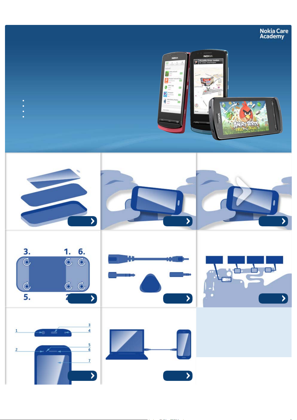
Exploded view Disassembly steps Disassembly video
More More More
Assembly hints Service devices Solder components
More More More
Product controls and interfaces Service concept
More More
©2011 Nokia
Service Manual Level 1 and 2
Nokia 700
RM-670
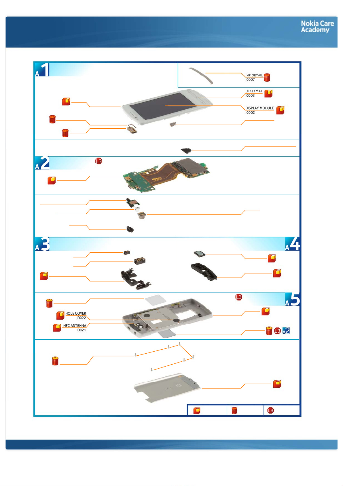
A-COVER ASSEMBLY
(I0001 - I0006)
A-COVER
I0001
Exploded view
EARPIECE GASKET
LIGHT SWAP PACKAGE
(I0008, I0009)
LIGHT SWAP PWB
NFC MECHANICAL ASSEMBLY
FLASH REFLECTOR
SECONDARY ANTENNA ASSEMBLY
(I0013 - I0015)
SECONDARY ANTENNA
I0004
EARPIECE
I0005
I0008
I0011
I0012
USB BOOT
I0018
DC JACK
I0014
AV JACK
I0013
I0015
CAPTURE SWITCH
I0006
BATTERY CONNECTOR SEALING
I0019
CAMERA
I0010
MAIN ANTENNA ASSEMBLY
(I0016, I0017)
IHF SPEAKER
I0016
MAIN ANTENNA
I0017
TEST PAD ADHESIVE
I0020
SCREW TORX+
SIZE 4 M1.0x3.8
I0024
©2011 Nokia
Only available
as assembly
D-COVER ASSEMBLY
(I0020 - I0023)
D-COVER
I0023
TYPE LABEL
I0009
BATTERY COVER
I0025
Not reuseable
after removal
Repair/swap
only in level 3
Service Manual Level 1 and 2
Nokia 700
RM- 670
Disassembly steps
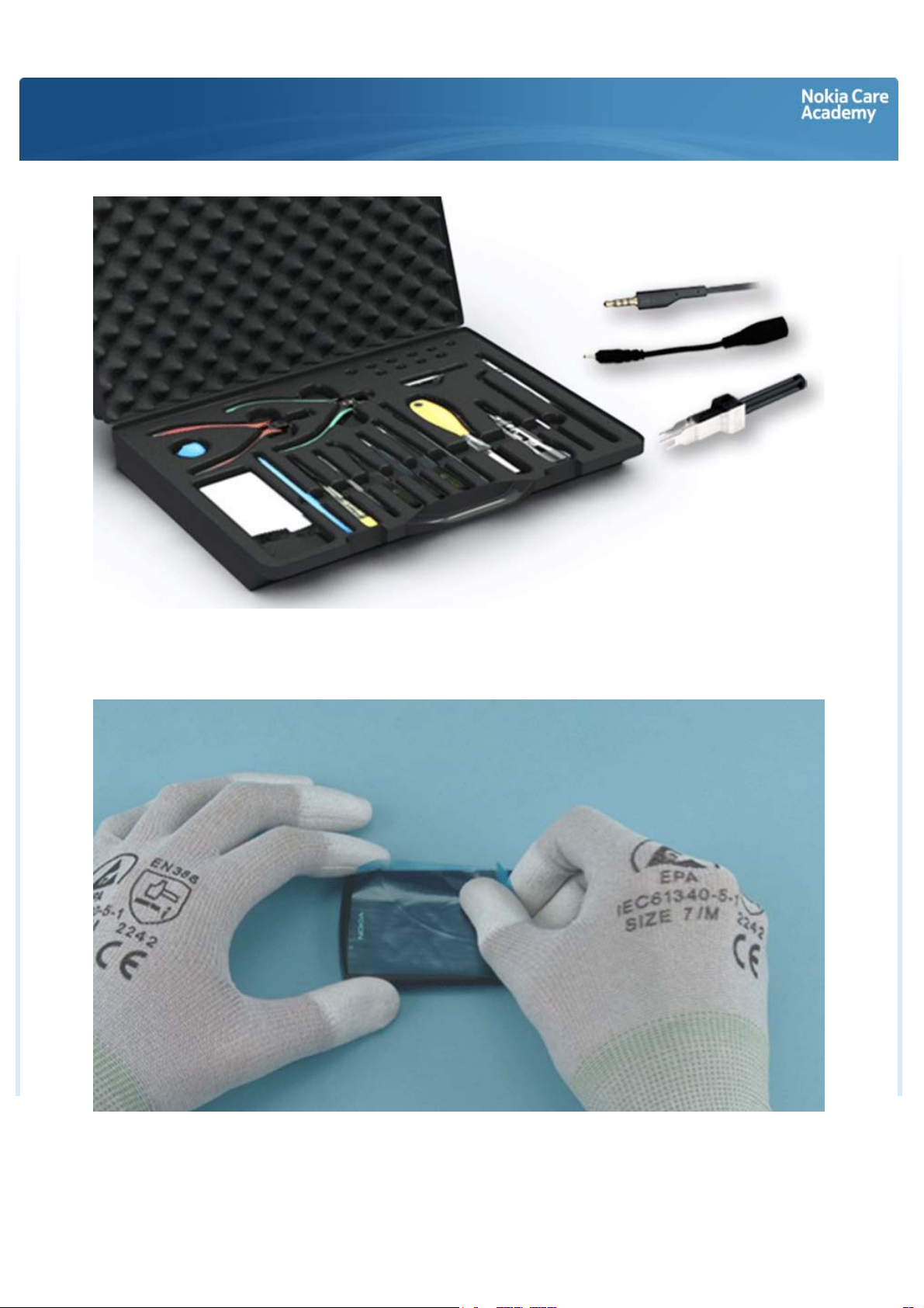
You must use the Nokia Standard Toolkit version 2. You will also need a DC plug, an AV plug and the SS88 camera removal tool.
Protect the A-COVER with protective film.
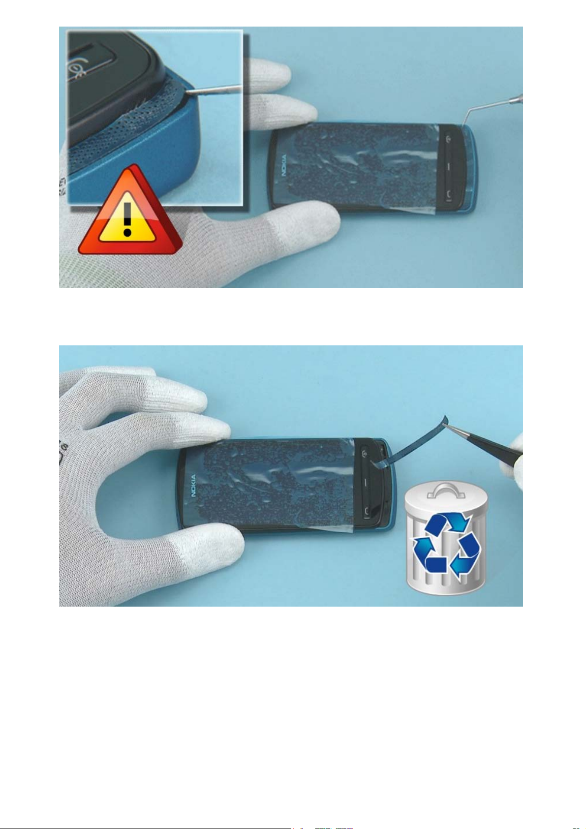
Use the dental tool to peel out one corner of the IHF DETAIL. Be careful not to injure yourself or damage
the A-COVER with the sharp end of the dental tool.
Remove the IHF DETAIL with the tweezers. Do not use it again. Discard it.
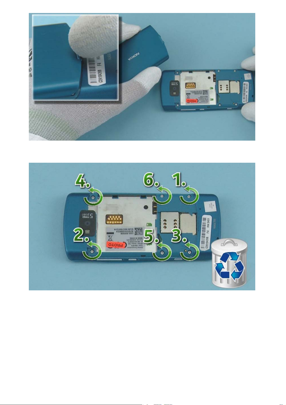
Open the BATTERY COVER by using the release button. Lift up and remove the BATTERY COVER.
Unscrew the six Torx+ size 4 screws in the order shown. Do not use them again. Discard them.
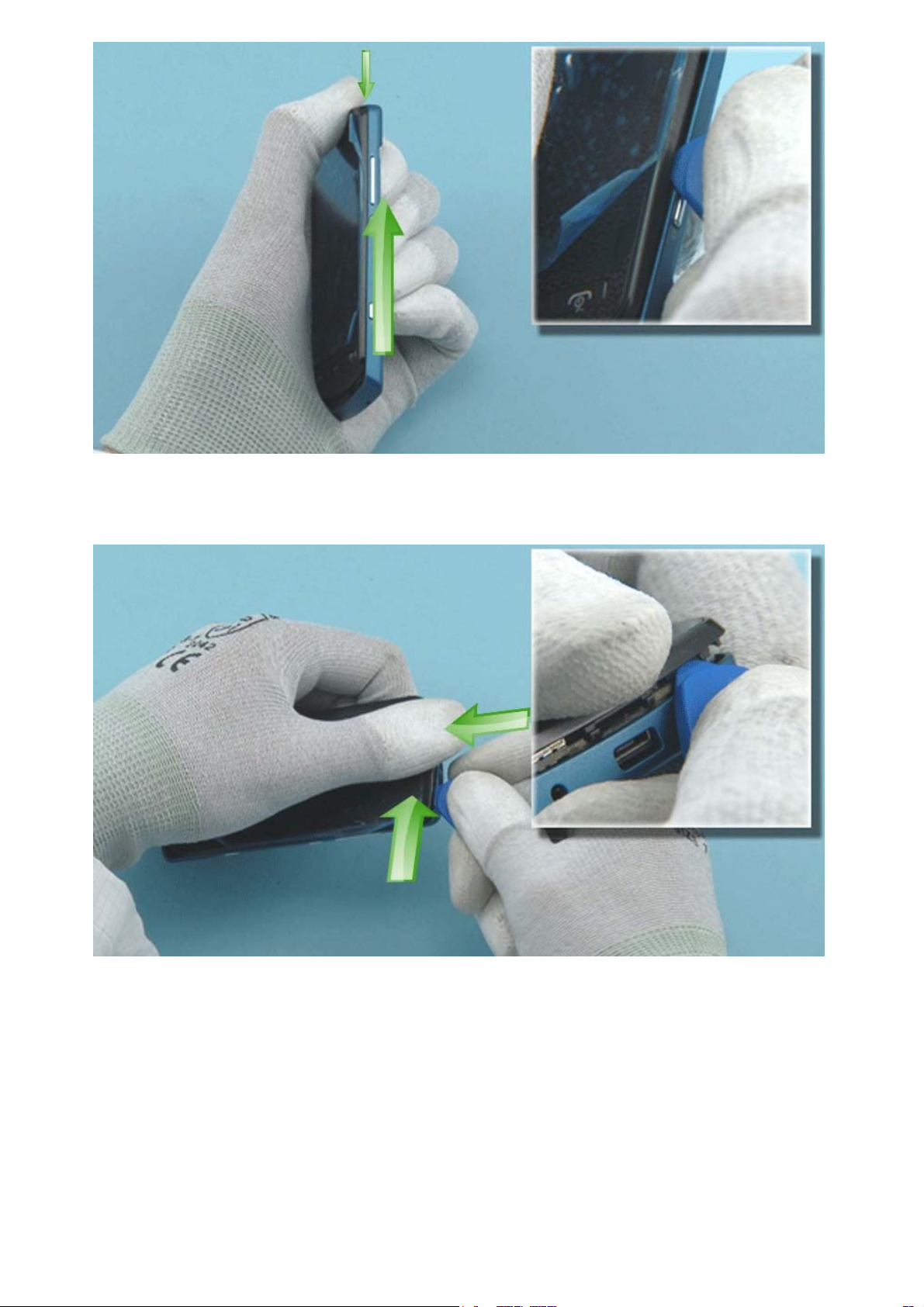
Press down the A-COVER from the top side with your thumb and slide the SRT-6 to direction shown to
release the right side of the A-COVER. This way the hooks holding the A-COVER will not get damaged.
Keep pressing down the A-COVER from the top side and open the top side of the A-COVER by sliding the
SRT-6 to direction shown.
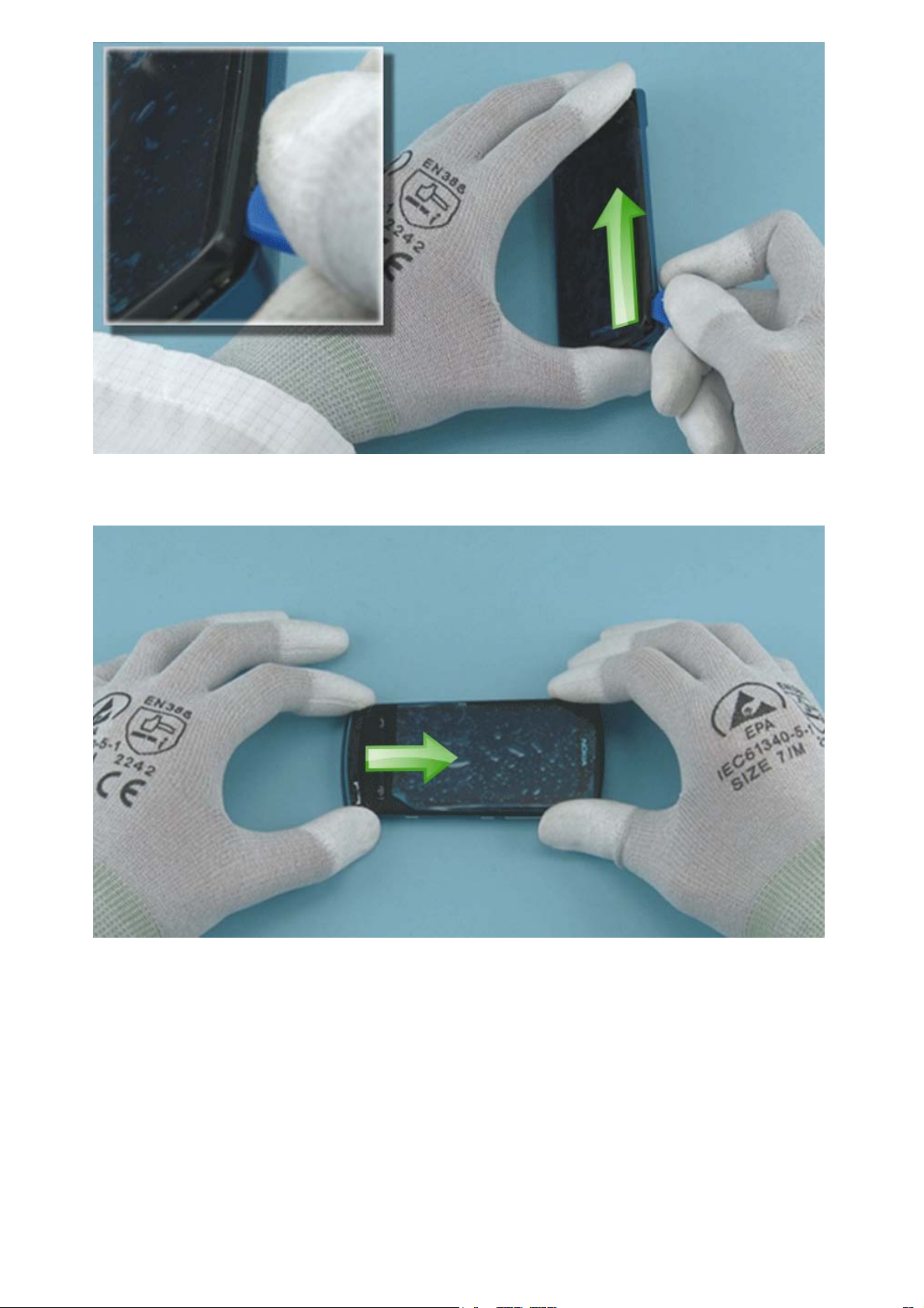
Open also the left side of the A-COVER by sliding the SRT-6 towards the bottom end.
Carefully pull the A-COVER to direction shown to release the bottom end.
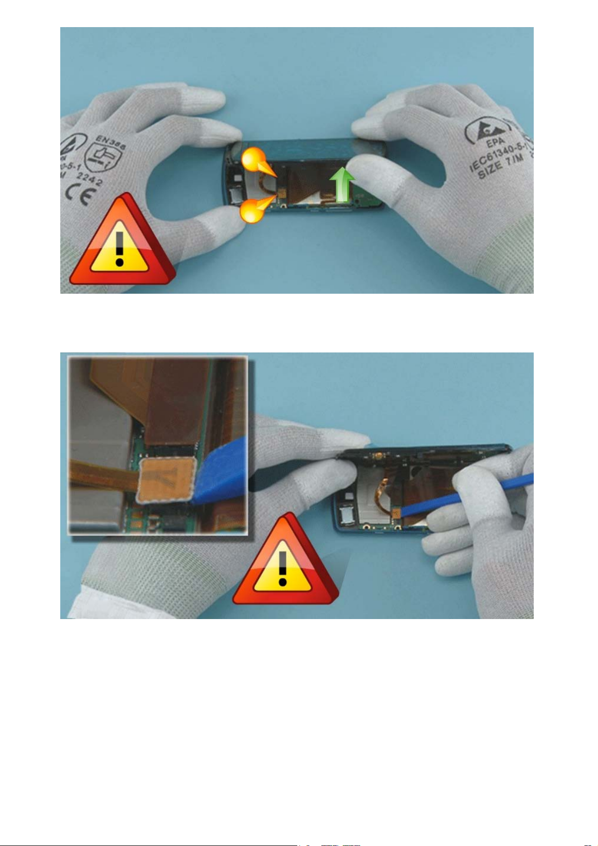
Lift up the right side of the A-COVER as shown. Note that the A-COVER must not be lifted up completely
to avoid damaging the flexes underneath.
Use the SS-93 to open the UI connector. Be careful not to damage the connector or any nearby
components.
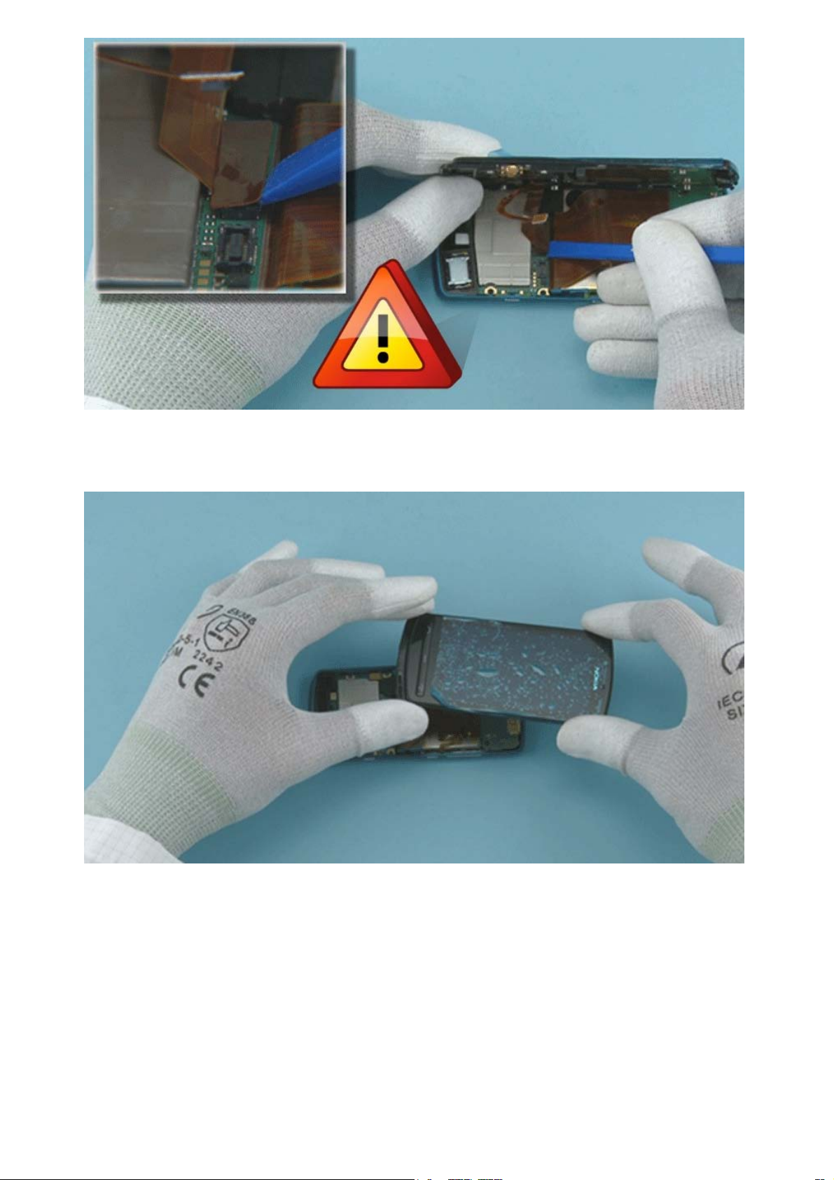
Open also the DISPLAY connector with the SS-93. Be careful not to damage the connector or any nearby
components.
The A-COVER can now be separated.
 Loading...