

Page 1

CCS Technical Documentation
NSB-9 Series Transceivers
Disassembly and Assembly
Instructions
Issue 1 04/03 Nokia Corporation.
Page 2
NSB-9 Company confidential
Disassembly and Assembly Instructions CCS Technical Documentation
Table of Content
Page No
Disassembly Instructions ............................................................................................... 3
Exchange of dome sheet ................................................................................................ 8
Page 2 Nokia Corporation. Issue 1 04/03
Page 3
Company confidential NSB-9
CCS Technical Documentation Disassembly and Assembly Instructions
Disassembly Instructions
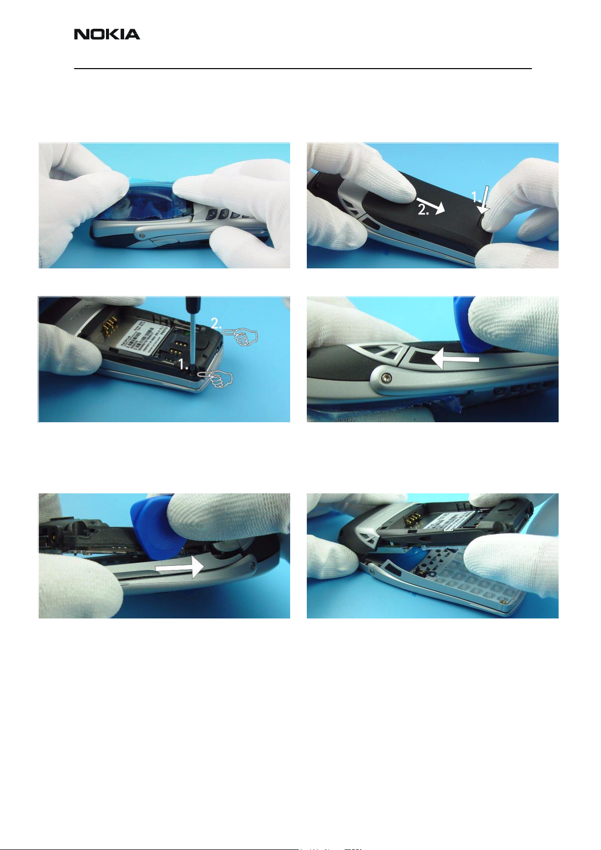
Protect LCD window to avoid dust and scratches.
Unscrew the two TORX PLUS® size 6 screws using the
order shown. For assembly, the reverse order and a
torque of 17Ncm have to be used.
Press Release Button before removing Battery Cover.
Place the SRT-6 between B-Cover and A-Cover and
shift it carefully as shown in the picture. Note the
correct position of the SRT-6, the tip should not
touch the PWB.
Now, the same procedure on the other side. Separate the modules.
Issue 1 04/03 Nokia Corporation. Page 3
Page 4

NSB-9 Company confidential
Disassembly and Assembly Instructions CCS Technical Documentation
Protect LCD to avoid dust and scratches. Keymat drops out when turning A-Cover.
Open the Flip Cover.
Function Keys are attached with four snaps to Acover. Use SRT-6 to release the snaps. Take care not to
damage the spring contacts.
Separate A-Cover from Flip Cover as shown in the picture. Note the right position of the Flip Hinges on
reassembly.
Remove Function Keys if needed. Use always new keys
in reassembly!
Page 4 Nokia Corporation. Issue 1 04/03
Page 5

Company confidential NSB-9
CCS Technical Documentation Disassembly and Assembly Instructions
Unscrew the five TORX PLUS® size 6 screws using the
order shown. For assembly, the reverse order and a
torque of 17Ncm have to be used.
Open the Light Guide snaps. Remove the Light Guide.
Lift the engine from B-Cover.
The LCD Metal Frame is attached with snaps to the
Radio Module on both sides.
Note the right position of the LCD Module in LCD
Metal Frame when assembling. Also take care not to
damage the LCD spring contacts of Radio Module.
Issue 1 04/03 Nokia Corporation. Page 5
Release the snap on the other side of the engine and
take away the LCD Module.
Separate the LCD Metal Frame from LCD Module and
protect the LCD window again.
Page 6

NSB-9 Company confidential
Disassembly and Assembly Instructions CCS Technical Documentation
Do not remove the Earpiece from the LCD Frame, as
they are supplied as one part.
To remove the DC Jack, place tweezers between the
spring contacts and under the Jack. You’ll need to use
additional force to pull the Jack upwards.
Volume Key can be removed easily.
Use tweezers to pull up the Microphone.
Remove the Vibra Motor from its guidance. Place the SRT-6 between the spring contacts and lift
up the Antenna carefully. Do not damage the spring
contacts and the Antenna Radiator when removing
the Antenna.
Page 6 Nokia Corporation. Issue 1 04/03
Page 7

Company confidential NSB-9
CCS Technical Documentation Disassembly and Assembly Instructions
Remove the Antenna from B-Cover. The Logo Bracket is attached with snaps to the B-
Cover. Take care not to break the snaps when releasing the Bracket.
After releasing of the snaps, the Logo Bracket can be
removed.
Issue 1 04/03 Nokia Corporation. Page 7
Page 8

NSB-9 Company confidential
Disassembly and Assembly Instructions CCS Technical Documentation
Exchange of dome sheet
Remove the defective Dome Sheet carefully. Put the new Dome Sheet onto the Dome Sheet
Assembly Jig. Note the guiding pins.
Place the Radio Module on the Jig. Press on the Radio Module evenly.
Lift the Radio Module with the new Dome Sheet from
the Jig.
Check that the Dome Sheet is correctly stuck to the
Radio Module. Do not damage the spring contacts of
LCD.
Page 8 Nokia Corporation. Issue 1 04/03
 Loading...