

Page 1

CCS Technical Documentation
NSB-9 Series Transceivers
Service Software Instructions
Draft 1 02/03 Copyright Nokia. All rights reserved.
Page 2
NSB-9
Service Software Instructions CCS Technical Documentation
[This page left intentionally blank]
Page 2 Copyright Nokia. All rights reserved. Draft 1 02/03
Page 3

CCS Technical Documentation
Quick Guide for Phoenix Service SW Installation ........................................................ 5
Phoenix Installation Steps in Brief ..............................................................................5
Phoenix Service SW....................................................................................................... 6
Before Installation .......................................................................................................6
Startup ..........................................................................................................................7
Dongle Driver Installation and Version Check ...........................................................8
First Time Installation of Phoenix ...............................................................................9
Update Installation of Phoenix ..................................................................................12
How to Uninstall Phoenix ..........................................................................................13
Data Package for Phoenix (Product Specific).............................................................. 15
Before installation ......................................................................................................15
Installation of Phoenix Data Package (Product Specific) ..........................................16
How to Uninstall Data Package .................................................................................19
How to Manage Connections .....................................................................................20
How to Update Flash Support Files for FPS-8* and FLS-4* ...................................... 23
Before Installation .....................................................................................................23
Installing the Flash Support Files ..............................................................................23
How to Update The FPS-8* Flash Prommer SW ......................................................26
FPS-8 Activation and Deactivation.............................................................................. 28
Activation ..................................................................................................................28
Deactivation ...............................................................................................................30
JBV-1 Docking Station SW ......................................................................................... 31
Before Installation .....................................................................................................31
Installing SW Needed for the JBV-1 SW Update .....................................................32
Updating the JBV-1 Docking Station Software .........................................................36
Receiver tuning: Quick Guide for Tuning With Phoenix ............................................ 39
General remarks .........................................................................................................39
RF Tuning and Calibration Instructions for Iris HDB58 ............................................. 40
Introduction ................................................................................................................40
RX tunings .................................................................................................................40
TX tunings .................................................................................................................44
TX IQ Tuning ............................................................................................................45
Service Tool Concept For Baseband Tuning Operations............................................. 46
Service Concept for NSB-9 Baseband tunings ..........................................................47
Baseband Tuning operations........................................................................................ 48
Energy Management Tuning .....................................................................................48
LCD Contrast Tuning ................................................................................................50
Flashing Setup Instructions.......................................................................................... 71
POS (Point of Sale) Flash Concept .........................................................................71
Flash Concept with flashing adapter............................................................................ 72
Module Jig Concept ..................................................................................................... 73
JBV-1 Flash Concept .................................................................................................74
Service Concept .........................................................................................................76
Parallel Flash concept ................................................................................................77
NSB-9
Issue 1 04/03 Copyright Nokia. All rights reserved.. Page 1
Page 4
NSB-9
CCS Technical Documentation
Page 2 Copyright Nokia. All rights reserved. Issue 1 04/03
Page 5

Company confidential NSB-9
CCS Technical Documentation
Quick Guide for Phoenix Service SW Installation
Phoenix Installation Steps in Brief
DCT-4 generation Test and Service Software is called “Phoenix”
These are the basic steps to install the Phoenix
• Install the Phoenix Service SW
• Install the Data Package for Phoenix (product specific data and flash update package)
• Manage connection settings (depends on the tools you are using)
• Update FPS-8 SW (if you use FPS-8)
• Activate FPS-8
• Update JBV-1 Docking Station SW (only when needed)
The flash update files are delivered with then Phoenix Data Package so unless you want
to use certain version of this package, separate installation package is not needed anymore. If you want to use it, it should be installed after connection management, before
FPS-8 update.
Please refer to Service Manual and Technical Bulletins for more information concerning phone model specific service tools and equipment setup.
Issue 1 04/03 Copyright Nokia. All rights reserved. Page 5
Page 6

NSB-9 Company confidential
Phoenix Service SW
Before Installation
• Check that a Dongle is attached to the parallel port of your computer.
• Download the installation package (e.g.
phoenix_service_sw_a3_03_83_005.exe) to your computer (e.g. C:\TEMP)
• Close all other programs
• Run the application file (e.g. phoenix_service_sw_a3_03_83_005.exe) and
follow instructions on the screen
• Administrator rights may be required to be able to install Phoenix depending
on the Operating System
• If the dongle driver is installed or updated, you need to reboot your PC before
the installation can continue.
CCS Technical Documentation
• If uninstalling or rebooting is needed at any point, you will be prompted by the
Install Shield program.
If at any point during installation you get this message, Dongle is not found and installation can´t continue.
Possible reasons may be defective or too old PKD-1Dongle (five digit serial number Dongle when used with FPS-8 Prommer) or that the FLS-4S POS Flash Dongle is defective or
power to it is not supplied by external charger.
Check the COM /parallel ports used first! After correcting the problem Installation can be
restarted.
Page 6 Copyright Nokia. All rights reserved. Issue 1 04/03
Page 7
Company confidential NSB-9
CCS Technical Documentation
Startup
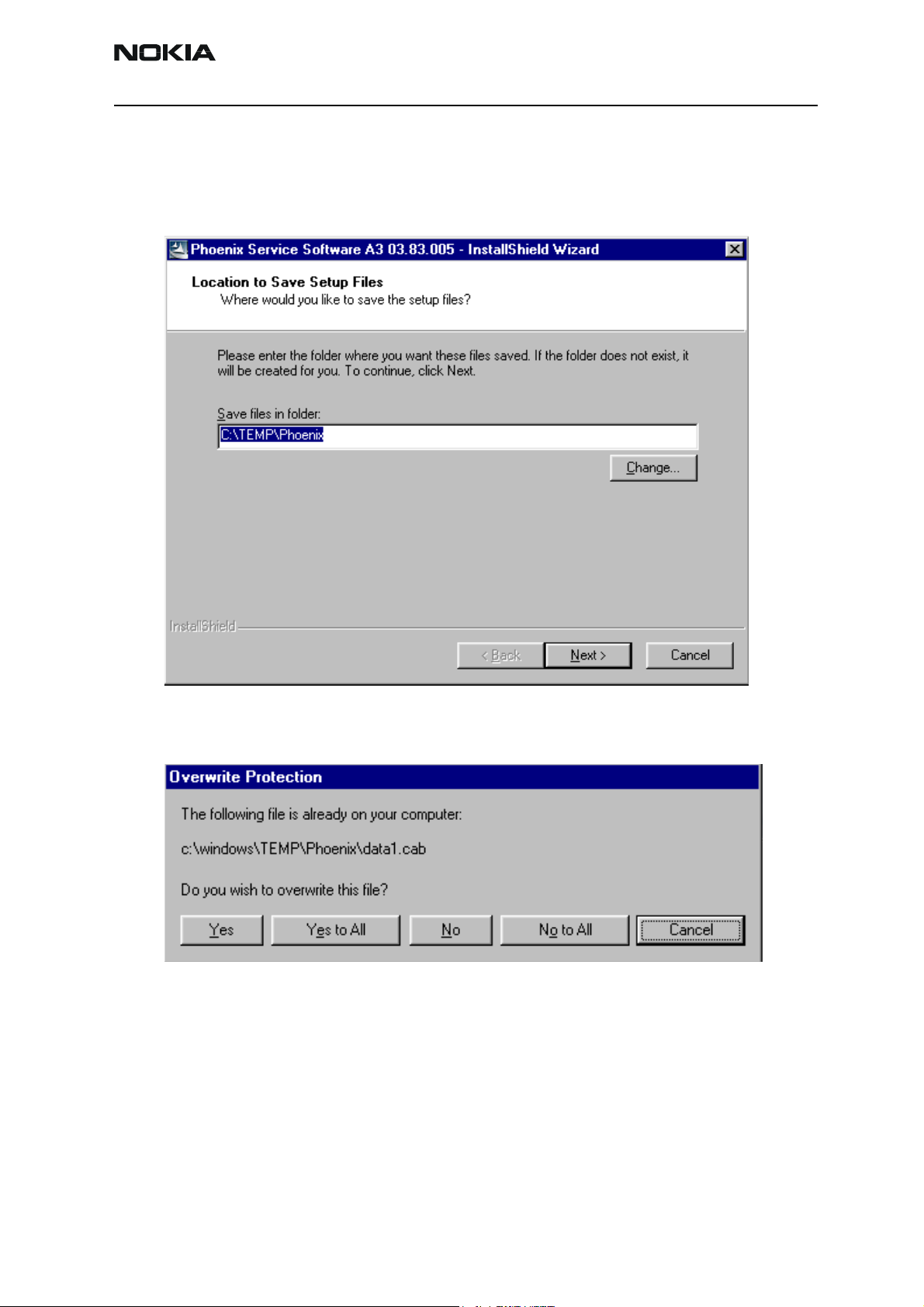
Run the phoenix_service_sw_a3_03_83_005.exe to start installation.
When you choose “Next” the files needed for installation will be extracted. Kindly wait.
If the setup files are already extracted (left in the file system from previous installation)
following dialog appears. Always click "Yes to All" to overwrite the existing setup files.
Issue 1 04/03 Copyright Nokia. All rights reserved. Page 7
Page 8

NSB-9 Company confidential
Dongle Driver Installation and Version Check
If there is no previously installed Dongle driver, installation will take place...
If the Dongle driver is installed and it is older than the latest supported version, the latest
version will be installed when you choose “Yes”. The latest version is always included in
the latest Phoenix installation package.
CCS Technical Documentation
PC needs to be rebooted before installation can continue. Click "Yes" to reboot the PC.
Setup is restarted automatically after reboot.
Page 8 Copyright Nokia. All rights reserved. Issue 1 04/03
Page 9
Company confidential NSB-9
CCS Technical Documentation
First Time Installation of Phoenix
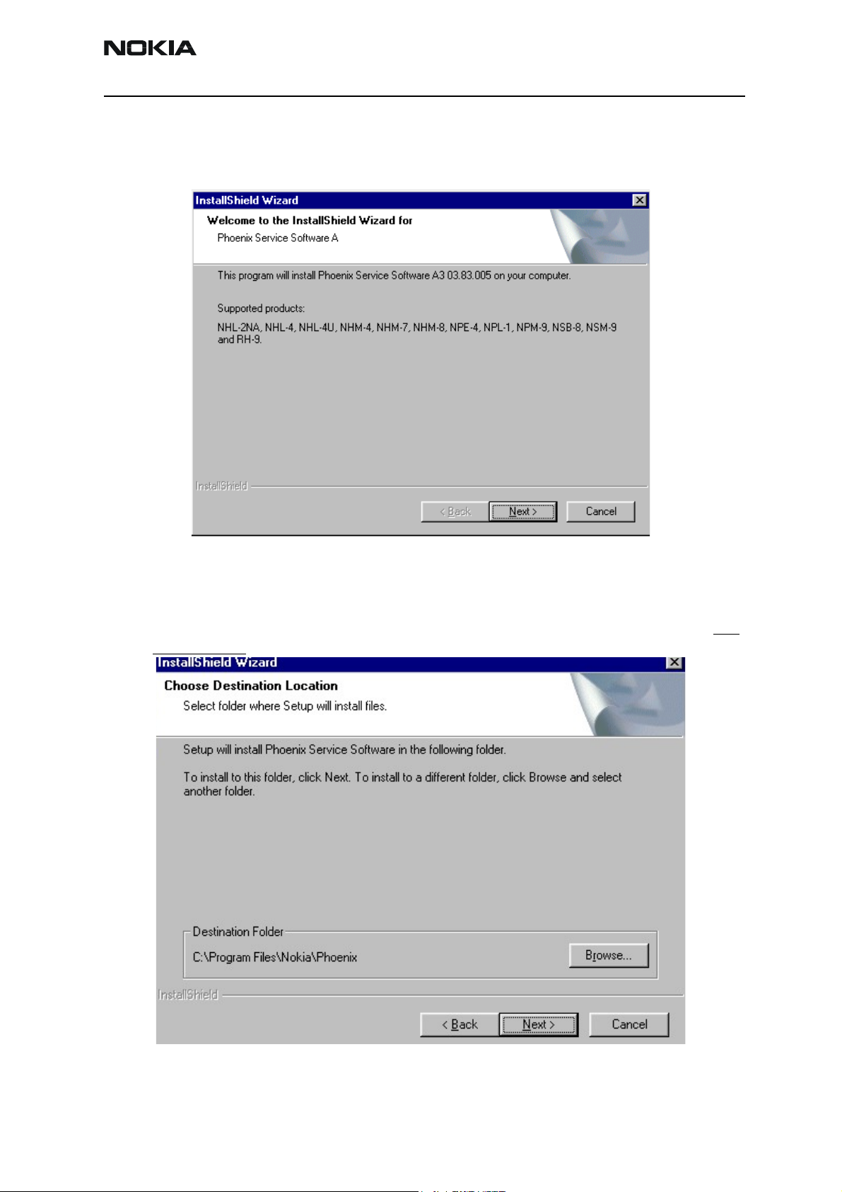
After Dongle driver installation / update (if needed) installation continues from this step.
Click "Next" in Welcome dialog to continue.
Choose the destination folder, it is recommended to use the default folder C:\Program-
Files\Nokia\Phoenix.
Choose “Next” to continue. You may choose another location by selecting “Browse” (not
recommended)
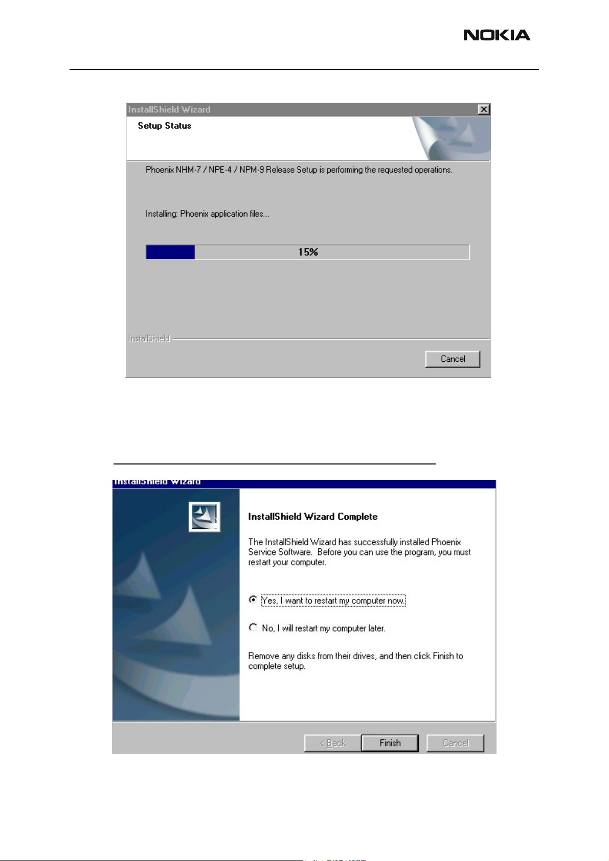
Setup copies the components, please wait.
Issue 1 04/03 Copyright Nokia. All rights reserved. Page 9
Page 10
NSB-9 Company confidential
Progress of the setup is shown. Please wait…
CCS Technical Documentation
If restarting of your computer is needed the Install Shield Wizard will tell you about it.
Select "Yes..." to reboot the PC immediatelly and "No..." to reboot the PC manually.
Note that Phoenix doesn't work, if components are not registered
continue.
. Click "Finish" to
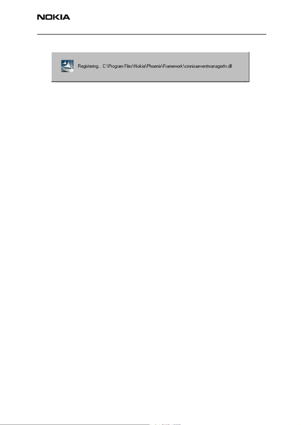
After the reboot components are registered and Phoenix is ready for use.
Page 10 Copyright Nokia. All rights reserved. Issue 1 04/03
Page 11
Company confidential NSB-9
CCS Technical Documentation
If reboot is not needed components are registered after copying them.
If restarting of your computer is not needed, Click "Finish" to exit the setup.
Phoenix is now ready for use.
Now the installation of Phoenix Service SW is ready and it can be used after:
• Installing Phone model specific Phone Data Package for Phoenix
• Configuring the connections
• Updating the Flash Update Package files used with FPS-8* and FLS-4* tools
Issue 1 04/03 Copyright Nokia. All rights reserved. Page 11
Page 12

NSB-9 Company confidential
Update Installation of Phoenix
If you already have the Phoenix Service SW installed on your computer, sooner or later
there will be need to update it when new versions are released.
Please note that very often the Phoenix Service SW and the Phone Specific Data Package
for Phoenix come in pairs, meaning that certain version of Phoenix can only be used with
certain version of Data Package. Always use the latest available versions of both. Instructions can be found in phone model specific Technical Bulletins.
To update the Phoenix you need to take exactly the same steps as when installing it for
the first time.
• Download the installation package to your computer hard disk
• Close all other programs
• Run the application file (e.g. phoenix_service_sw_a3_03_83_005.exe)
CCS Technical Documentation
• Dongle driver version will be checked and if need be, updated
• After reboot installation starts automatically
• Newer version of Phoenix will be installed
When you update the Phoenix from old to new version (e.g. update from 3.83.005 to
3.83.005
5), the update will take place automatically without uninstallation
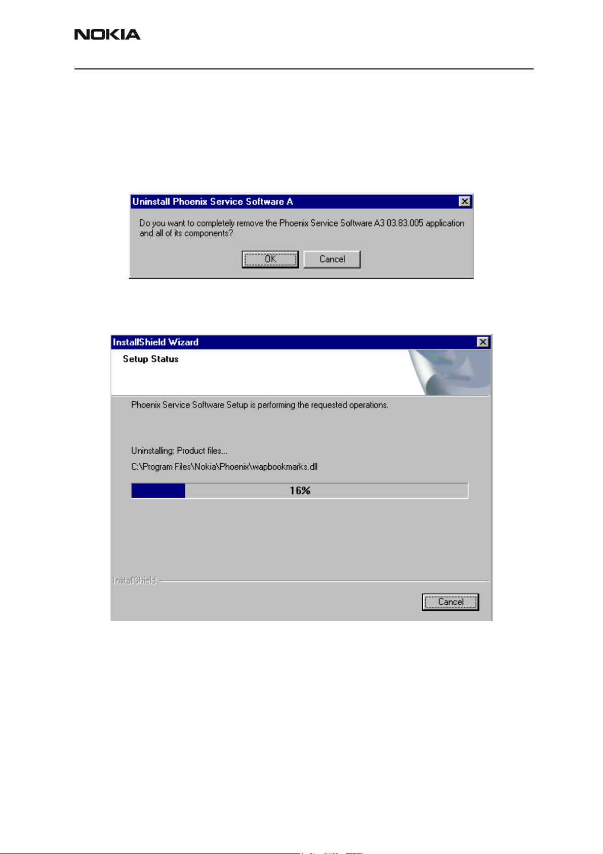
If you try update the Phoenix with the same version that you already have (e.g. 3.55 to
3.55) you are asked if you want to uninstall the version of Phoenix you have on your PC.
Answer “OK” to uninstall Phoenix, “Cancel” if you don’t want to uninstall.
If you try to install an older version (e.g. downgrade from 3.83.005 to 3.83.005) installation will be interrupted.
Always follow the instructions on the screen.
Page 12 Copyright Nokia. All rights reserved. Issue 1 04/03
Page 13
Company confidential NSB-9
CCS Technical Documentation
How to Uninstall Phoenix
Uninstallation can be done manually from Windows Control Panel - Add / Remove Programs.
Choose “Phoenix Service Software” and click "Add/Remove".
Choose “OK” to uninstall
Progress of the uninstallation is shown.
Issue 1 04/03 Copyright Nokia. All rights reserved. Page 13
Page 14

NSB-9 Company confidential
You may have to reboot the PC after uninstallation.
CCS Technical Documentation
If restarting is not needed, the following dialog will appear:
Note! If you have different product packages installed, components are uninstalled only if they are not
included in other product packages.
Page 14 Copyright Nokia. All rights reserved. Issue 1 04/03
Page 15

Company confidential NSB-9
CCS Technical Documentation
Data Package for Phoenix (Product Specific)
Before installation
Product Data Package contains all product specific data to make the Phoenix Service
Software and tools usable with a certain phone model.
It also includes the latest version of flash update package for FLS-4* and FPS-8*
• Check that the Dongle is attached to the parallel port of your computer.
• Install Phoenix Service SW
• Download the installation package (e.g. NSB-9_dp_1.00.exe) to your computer
(e.g. C:\TEMP)
• Close all other programs
• Run the application file (e.g.NSB-9_dp_1.00.exe) and follow instructions on the
screen
If you already have the Phoenix Service SW installed on your computer, sooner or later
there will be need to update it when new versions are released.
Please note that very often the Phoenix Service SW and the Phone Specific Data Package
for Phoenix come in pairs, meaning that certain version of Phoenix can only be used with
certain version of Data Package. Always use the latest available versions of both. Instructions can be found in phone model specific Technical Bulletins.
Issue 1 04/03 Copyright Nokia. All rights reserved. Page 15
Page 16
NSB-9 Company confidential
CCS Technical Documentation
Installation of Phoenix Data Package (Product Specific)
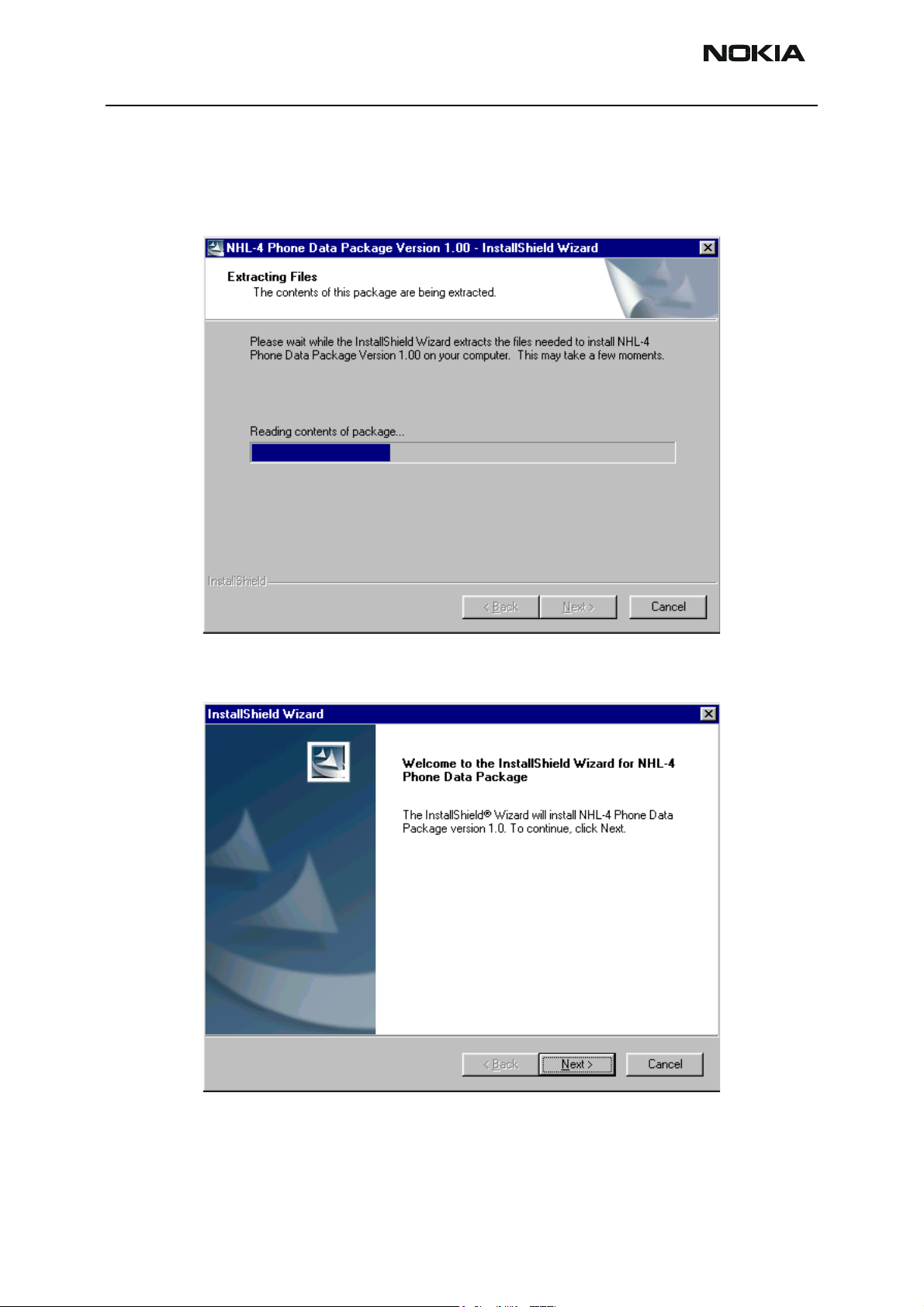
Run the
When you choose “Next” the files needed for installation will be extracted. Please wait…
NSB-9_dp_v_1.00.exe
to start installation.
Choose “Next” to continue.
From this view you can see the contents of the Data Package.
Read the text carefully.
Page 16 Copyright Nokia. All rights reserved. Issue 1 04/03
Page 17

Company confidential NSB-9
CCS Technical Documentation
There should be information about the Phoenix version needed with this data package.
Choose “Next”.
Confirm location and choose “Next” to continue.
Install Shield checks where the Phoenix application is installed and the directory is
shown. Choose “Next” to continue.
Phone model specific files will be installed... please wait.
Issue 1 04/03 Copyright Nokia. All rights reserved. Page 17
Page 18

NSB-9 Company confidential
CCS Technical Documentation
Choose “Finish” to complete installation.
You now have all phone model specific files installed in your Phoenix Service SW.
Page 18 Copyright Nokia. All rights reserved. Issue 1 04/03
Page 19
Company confidential NSB-9
CCS Technical Documentation
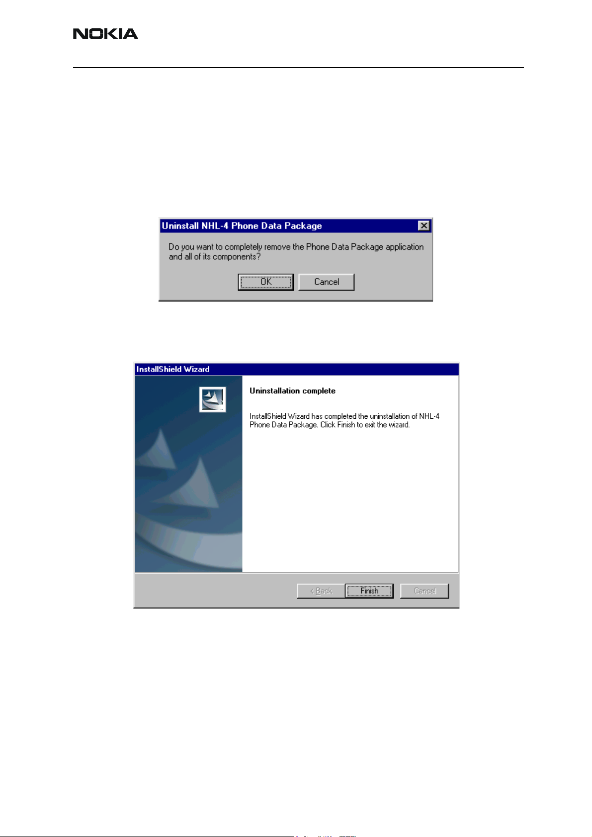
How to Uninstall Data Package
Uninstallation can also be done manually from Windows Control Panel / Add / Remove
Programs/ “NSB-9 Phone Data Package”.
If you try to install the same version of Phoenix Data Package that you already have, you
are asked if you want to uninstall the version you have on your PC. Answer “OK” to uninstall, “Cancel” if you don’t want to uninstall. Older versions of data packages do not need
to be uninstalled.
Once the previously installed Data package is uninstalled, choose “Finish”.
Run the
Issue 1 04/03 Copyright Nokia. All rights reserved. Page 19
NSB-9_dp_v_1.00.exe
again to continue installation from the beginning.
Page 20

NSB-9 Company confidential
How to Manage Connections
Start Phoenix Service SW and Login.
Choose “Manage Connections” From “File” – Menu
CCS Technical Documentation
Existing connections can be selected, edited, deleted and new ones created by using this
dialog.
A connection can be created either manually or by using a Connection Wizard.
To add new connection, choose “Add” and select if you want to create it manually or by
using the Wizard.
Choose “Next” to continue.
Page 20 Copyright Nokia. All rights reserved. Issue 1 04/03
Page 21

Company confidential NSB-9
CCS Technical Documentation
In the next dialogs you will be asked to select some settings for the connection
Manual Settings
A) For FLS-4S POS Flash Device choose following connection settings
Media: FBUS
COM Port: Virtual COM Port used by FLS-4 Please check this always!
(To check please go to Windows / Control Panel / FLS Virtual Port / Configuration)
B) For FPS-8 Flash Prommer choose following connection settings:
Media: FPS-8
Port Num: COM Port where FPS-8 is connected
COMBOX_DEF_MEDIA: FBUS
Choose “Finish” to complete.
If you use the Wizard, connect the tools and a phone to your PC and the wizard will
automatically try to configure the correct connection.
Issue 1 04/03 Copyright Nokia. All rights reserved. Page 21
Page 22

NSB-9 Company confidential
Activate the connection you want to use by clicking it and use up/down arrows to move
it on top of the list. Choose “Apply”.
The connection is now selected and can be used after closing the “Manage Connections”
window.
CCS Technical Documentation
Selected connection will be shown on the right hand bottom corner of the screen.
To use the selected connection, connect the phone to Phoenix with correct service tools,
make sure that it is switched on and select “Scan Product”.
When the Product is found, Phoenix will load product support and when everything is
ready, name of the loaded product support module and its version will be shown on the
bottom of the screen.
Page 22 Copyright Nokia. All rights reserved. Issue 1 04/03
Page 23

Company confidential NSB-9
CCS Technical Documentation
How to Update Flash Support Files for FPS-8* and FLS-4*
Before Installation
• Install Phoenix Service SW and Phoenix data package.
• Install the phone model Specific Datapackage for Phoenix
• The flash support files are delivered in the same installation package
with Phoenix data package.
• Normally it is enough to install the data package only before updating
the FPS-8.
• Separate installation package is for flash support files are available, and
the files can be updated according to this instruction.
Installing the Flash Support Files
Start by double clicking eg. flash_update_02_10_00.exe. Installation begins.
If you already have the same Flash Update package files installed, you need to confirm if
you want them to be reinstalled.
Issue 1 04/03 Copyright Nokia. All rights reserved.. Page 23
Page 24

NSB-9 Company confidential
If you try to downgrade the existing version to older ones, the setup will be aborted. If
you really want to downgrade, uninstall newer files manually from Control Panel and
then rerun the installation again.
If an older version exists on your PC and it needs to be updated, choose “Next” to continue installation
CCS Technical Documentation
It is highly recommended to install the files to the default destination folder
Files\Nokia\Phoenix
Page 24 Copyright Nokia. All rights reserved. Issue 1 04/03
.
C:\Program
Page 25

Company confidential NSB-9
CCS Technical Documentation
Choose “Next” to continue. You may choose another location by selecting “Browse” (not
recommended).
Installation continues…
Choose “Finish” to complete procedure.
• FLS-4 can be used right after Flash Update Package is installed.
Issue 1 04/03 Copyright Nokia. All rights reserved.. Page 25
Page 26

NSB-9 Company confidential
• FPS-8* must be updated by using Phoenix!
CCS Technical Documentation
Page 26 Copyright Nokia. All rights reserved. Issue 1 04/03
Page 27

Company confidential NSB-9
CCS Technical Documentation
How to Update The FPS-8* Flash Prommer SW
Start Phoenix Service Software
Select”FPS-8 / FPS-8C maintenance” from”Flashing” menu.
When new FPS-8 flash update package is installed to computer you will be asked to
update the files to your FPS-8 Prommer. Select”Yes” to update files..
0200
Update procedure takes a couple of minutes.
Issue 1 04/03 Copyright Nokia. All rights reserved.. Page 27
Page 28

NSB-9 Company confidential
CCS Technical Documentation
FPS-8 sw can also be updated by pressing”Update” button and selecting appropriate
fps8upd.ini file under
All files can be loaded separately to FPS-8. To do this, just press right mouse button in
Flash box files” window and select file type to be loaded.
C:\Program Files\Nokia\Phoenix
\Flash - directory
More information and help can be found from the “Help” dialog.
Page 28 Copyright Nokia. All rights reserved. Issue 1 04/03
Page 29

Company confidential NSB-9
CCS Technical Documentation
FPS-8 Activation and Deactivation
• Before the FPS-8 can be successfully used for phone programming, it must be
first activated.
• If there is a need to send FPS-8 box to somewhere e.g. for repair, box must be
first deactivated.
Activation
Before FPS-8 can be successfully used for phone programming, it must be first activated.
Fill in first “FPS-8 activation request” sheet, in the FPS-8 sales package and follow the
instructions in the sheet.
When activation file is received (e.g. 00000.in), copy it to C:\Program-
Files\Nokia\Phoenix\BoxActivation - Directory on your computer
created when Phoenix is installed).
(This directory is
Start Phoenix Service Software.
Select ”FPS-8 / FPS-8C maintenance” from ”Flashing” menu.
Select “Activate” from the “FPS8/8C Maintenance” – UI.
Issue 1 04/03 Copyright Nokia. All rights reserved.. Page 29
Page 30

NSB-9 Company confidential
The activation file you saved to C:\ProgramFiles\Nokia\Phoenix\BoxActivation - directory
will be shown (e.g. 00000.in), check that it is correct.
CCS Technical Documentation
Box will be activated when you choose “Open”
Turn FPS-8 power off and on to complete activation
Page 30 Copyright Nokia. All rights reserved. Issue 1 04/03
Page 31

Company confidential NSB-9
CCS Technical Documentation
Deactivation
Start Phoenix Service Software.
Select ”FPS-8 / FPS-8C maintenance” from ”Flashing” menu
Select “Deactivate” from the “FPS8/8C Maintenance” – UI.
Confirm Deactivation by choosing “Yes”, Box will be deactivated.
Turn FPS-8 power off and on to complete deactivation
Issue 1 04/03 Copyright Nokia. All rights reserved.. Page 31
Page 32

NSB-9 Company confidential
JBV-1 Docking Station SW
The JBV-1 Docking Station is a common tool for all DCT-4 generation products. In order
to make the JBV-1 usable with different phone models, a phone specific Docking Station
Adapter is used for different service functions.
The JBV-1 Docking Station contains Software (Firmware) which can be updated.
You need the following equipment to be able to update JBV-1 software:
• PC with USB connection
• Operating System supporting USB (Not Win 95 or NT)
• USB Cable (Can be purchased from shops or suppliers providing PC hardware and
accessories)
• JBV-1 Docking Station
CCS Technical Documentation
• External Power Supply 11-16V
Before Installation
• Download Jbv1_update.zip – file to your computer (e.g. C:\TEMP) from your download web site.
• Close all other programs
• Follow instructions on the screen
Page 32 Copyright Nokia. All rights reserved. Issue 1 04/03
Page 33

Company confidential NSB-9
CCS Technical Documentation
Installing SW Needed for the JBV-1 SW Update
Note: DO NOT CONNECT THE USB CABLE / JBV-1 TO YOUR COMPUTER YET!
Run
Jbv1_update.zip
Files needed for JBV-1 Package setup Program will be extracted.
file and start SW Installation by double clicking
Setup.exe
.
Installation begins, please read the information shown and Choose “Next” to continue.
Use suggested destination folder where JBV-1 SW Package will be installed and choose
Issue 1 04/03 Copyright Nokia. All rights reserved.. Page 33
Page 34

NSB-9 Company confidential
“Next” to continue.
CCS Technical Documentation
Select “Full” Installation and choose “Next” to continue
Program Folder will be created. Choose “Next” to continue, Software files will be
Page 34 Copyright Nokia. All rights reserved. Issue 1 04/03
Page 35

Company confidential NSB-9
CCS Technical Documentation
installed.
After successful installation, choose “Finish” to complete.
NOW YOU CAN CONNECT THE USB CABLE / JBV-1 TO YOUR COMPUTER!
Connect power to JBV-1 (11-16V DC) from external power supply, then connect USB
Issue 1 04/03 Copyright Nokia. All rights reserved.. Page 35
Page 36

NSB-9 Company confidential
Cable between JBV-1 USB connector and PC.
Windows will detect connected USB cable and detect drivers for new HW.
Follow the instructions and allow Windows to search and install the best drivers available. After this procedure the actual JBV-1 SW update can begin.
CCS Technical Documentation
Page 36 Copyright Nokia. All rights reserved. Issue 1 04/03
Page 37

Company confidential NSB-9
CCS Technical Documentation
Updating the JBV-1 Docking Station Software
Go to folder C:\Program Files\Nokia\ JBV-1 SW Package\ FIRMWARE UPDATE and start
JBV-1 Update SW by double clicking fwup.exe.
JBV-1 Firmware update starts and shows current status of the JBV-1 connected.
If firmware version read from your JBV-1 is not the latest one available, it needs to be
updated by choosing “Update Firmware”.
Choose file JBV1v11.CDE (example used here is for v 11) and “Open” to update your JBV-
1.
After Successful update, current JBV-1 status will be shown. You have now updated the
Issue 1 04/03 Copyright Nokia. All rights reserved.. Page 37
Page 38

NSB-9 Company confidential
software of your JBV-1 docking station and it is ready for use.
CCS Technical Documentation
Page 38 Copyright Nokia. All rights reserved. Issue 1 04/03
Page 39

Company confidential NSB-9
CCS Technical Documentation
[This page left intentionally blank]
Issue 1 04/03 Copyright Nokia. All rights reserved.. Page 39
Page 40

NSB-9 Company confidential
CCS Technical Documentation
Page 40 Copyright Nokia. All rights reserved. Issue 1 04/03
Page 41

CCS Technical Documentation
Quick Guide for Tuning With Phoenix
NSB-9
General remarks
If baseband tunings are needed, they should be completed before the RF tunings.
Avoid unnecessary tuning – factory-tuning values are always the most accurate ones.
Screen shots described in this document may change as the service software is developed.
Kindly refer to the Phoenix help files, the phone model specific service manual and bulletins for help.
Issue 1 04/03 Copyright Nokia. All rights reserved.. Page 39
Page 42

NSB-9
CCS Technical Documentation
RF Tuning and Calibration Instructions for Iris HDB58
Introduction
This document describes the methods of RF tunings and calibrations for Iris NSB-9 transceiver. RF tunings are made using automatic setup in which Phoenix software controls the
phone via FBUS and the measurement equipment via GPIB bus.
Autotune feature is designed to align the product’s RF part easier and faster. By this autotune component the product is tuned automatically. Manual tuning is not available.
RF tunings must be performed if any RF components are changed. RF tunings shall be
done using MJS-48 module jig. MJS-48 jig loss figures can be found from "RF Service
Tools" chapter. MJF-32 with a coupler is not allowed to use for RF tuning purpose.
EQUIPMENT NEEDED:
• NSB-9 module jig MJS-48, power- and DAU-9S cables
• DC power supply 3.9 VDC >3A
• Transmitter tester (e.g. Agilent VSA E4406A)
• Signal generator for RX tuning (e.g. Agilent E4433B)
• RF splitter (e.g. Mini-Circuits ZAPD-21)
• 6 dB attenuator, between module jig and RF cable to the splitter (e.g.
Suhner)
• PC with GPIB bus adapter, Phoenix software and security dongle
(PKD1xx)
Page 40 Copyright Nokia. All rights reserved. Issue 1 04/03
Page 43

CCS Technical Documentation
NSB-9
Figure 1: RF tuning concept
Figure 2: Setup environment
Issue 1 04/03 Copyright Nokia. All rights reserved.. Page 41
Page 44

NSB-9
Autotuning
The Autotune component can be found under Tuning menu:
When tuning, one only needs to click the Tune button to start automatic tuning procedure.
CCS Technical Documentation
Figure 3: Autotune menu in Phoenix
Figure 4: Autotune menu - RX/TX menu
The tuning results are shown in RX and TX windows.
Page 42 Copyright Nokia. All rights reserved. Issue 1 04/03
Page 45

CCS Technical Documentation
Set Loss
This is the component for saving RF-losses (of cables and jigs) to file. These loss values
are needed when you tune the phone with Phoenix (using Auto-Tune component). When
you measure the losses you have to be very careful, because these values affect directly
how well the phone is tuned.
NSB-9
Figure 5: Set Loss menu
Note! Components are protected by PKD-1CS, PKD-1NS, PKD-1 and PKD-1P dongles using standard
TSS protection procedure. Autotuning itself is possible with all these dongles but with PKD-1P and
PKD-1 dongles user is not able to set the loss.
Figure 6: Loss values
Issue 1 04/03 Copyright Nokia. All rights reserved.. Page 43
Page 46

NSB-9
RX tunings
Channel Select Filter Calibration
Description
Rx Channel select filter is tuned only in one band. The Hagar RF IC contains tunable filters for the I and Q channels. The calibration of these filters is carried out with a calibration circuit integrated in the IC.
By writing different control words to the Calibration Control Register in Hagar, internal
switches will connect various RC combinations between the TXC input line and the RXQ
output line.
During the calibration, the DSP generates a 67.71 kHz sine wave on the TXC line and
simultaneously receive the measured response from the Hagar on the RXQ line.
Altogether 6 measurements are made. The first measurement is a reference measurement where the TXC signal is routed directly to the RXQ line without going through any
filter. The remaining 5 measurements are all done on first order low pass filters with a
nominal corner frequency of 67.71 kHz. This means that the received signal on the RXQ
line ideally will have an amplitude of 0.707 times the amplitude of the TXC.
CCS Technical Documentation
Saved tuning values are:
DTOS_I Calibration of I-channel DtoS collector resistances
DTOS_Q Calibration of Q-channel DtoS collector resistances
BIQUAD_I_R Calibration of I-channel filter resistances
BIQUAD_Q_R Calibration of Q-channel filter resistances
BIQUAD_I_C Calibration of I-channel filter capacitances
BIQUAD_Q_C Calibration of Q-channel filter capacitances
Table 1: Channel Select Filter Calibration Limits
Item Typical value Low limit *) High limit *)
DTOS_I 12...18 -6 37
DTOS_Q 12...18 -6 37
BIQUAD_I_R 12...20 -6 37
BIQUAD_Q_R 12...20 -6 37
BIQUAD_I_C 6...16 -6 37
BIQUAD_Q_C 6...16 -6 37
Page 44 Copyright Nokia. All rights reserved. Issue 1 04/03
Page 47

CCS Technical Documentation
*) Tuning may return values between -6...37 but values between 0...31 are saved to phone
permanent memory. Values -6...0 are round up to 0 and values 31...37 are round down to
31.
RX Calibration
Description
Calibrates 26 MHz voltage controlled reference oscillator VCTCXO at the beginning of
GSM850 receiver gain (RSSI) tuning. AFC control voltage for VCTCXO is produced using
11-bits DA-converter inside UEM RF IC. AFC DAC value (AFC VALUE) which gives correct
VCTCXO output frequency is defined by measuring RX I/Q signal frequency and by adjusting AFC to set correct frequency. AFC VALUE is used as an init value when phone has not
found a base station signal yet.
After correct AFC VALUE is found, AFC value is changed to different value. RX I/Q frequency is measured again and AFC SLOPE (frequency change divided by AFC value
change) is calculated.
NSB-9
GSM850 and GSM1900 RX chains gain are tuned at middle channel.
Table 2: RX Calibration Limits
Band GSM850 GSM1900
Item Typical value
AFC VALUE -300...0 -350 350 NA NA NA
AFC SLOPE 240...260 150 350 NA NA NA
RSSI 0 74...76 65 85 67...71 59 79
RSSI 1 84...86 75 95 77...81 69 89
RSSI 2 94...96 85 105 87...91 79 99
RSSI 3 101...103 91 111 96...99 88 108
RSSI 4 111...113 101 121 106...129 98 11 8
RSSI 5 121...123 111 131 116...119 108 128
RSSI 6 131...133 121 141 126...129 11 8 138
RSSI 7 141...143 131 151 136...139 128 148
Low
limit
High
limit
Typical value
Low
limit
High
limit
RSSI 8 151...153 141 161 146...149 138 158
RX AM Suppression Calibration
Description
Calibrates GSM850 and GSM1900 RX mixer local signal DC-levels to achieve best rejection for AM modulated interferences. Calibration needs external AM modulated signal
applied to the phone. If tuning is successful, either LOP or LOM result in both branch (I
Issue 1 04/03 Copyright Nokia. All rights reserved.. Page 45
Page 48

NSB-9
CCS Technical Documentation
and Q) has always zero value.
Saved tuning values are:
LOP_I Calibration of Rx lower or upper band I channel positive lo bias
LOM_I Calibration of Rx lower or upper band I channel negative lo bias
LOP_Q Calibration of Rx lower or upper band Q channel positive lo bias
LOM_Q Calibration of Rx lower or upper band Q channel negative lo bias
AM Suppression Calibration Limits
Band GSM850 GSM1900
Item Typical value
RSSI -110...-85 -140 -80 -110...-90 -140 -80
LOP_I *) 0...1023 0 1023 0...1023 0 1023
LOM_I *) 0...1023 0 1023 0...1023 0 1023
LOP_Q *) 0...1023 0 1023 0...1023 0 1023
LOM_Q *) 0...1023 0 1023 0...1023 0 1023
Low
limit
High
limit
Typical value
Low
limit
*) 10-bits LOP/LOM results may also be introduced in two separate 5-bits results. Then
limits are 0 and 31 for each item.
RX Band Filter Response Compensation
Description
Calibrates GSM850 and GSM1900 RX chain gain over whole band. Calibration needs
external signal applied to the receiver. Calibration is done in 9 frequencies.
Table 3: RX Band Filter Response Compensation Limits
Band GSM850 GSM1900
High
limit
Item (850/1900) Typical value
ch 118 / 496 -2.6 ... -1.3 -10 5 -1.9 ... +0.5 -10 5
ch 128 / 512 -1.3 ... -0.3 -5 5 -0.3 ... +0.8 -5 5
ch 140 / 537 -0.4 ... +0.3 -5 5 0.0 ... +1.0 -5 5
ch 172 / 586 +0.3 ... +0.9 -5 5 +0.4 ... +1.1 -5 5
Low
limit
High
limit
Typical value
Low
limit
High
limit
Page 46 Copyright Nokia. All rights reserved. Issue 1 04/03
Page 49

CCS Technical Documentation
ch 190 / 661 +0.5 ... +1.0 -5 5 +0.4 ... +0.9 -5 5
ch 217 / 736 +0.1 ... +0.7 -5 5 -0.3 ... +0.3 -5 5
ch 241 / 794 -0.7 ... -0.1 -5 5 -0.9 ... 0.0 -5 5
ch 251 / 810 -1.2 ... -0.3 -5 5 -1.0... 0.0 -5 5
ch 261 / 835 -1.8 ... -0.8 -10 5 -2.1 ... -0.7 -10 5
NSB-9
Issue 1 04/03 Copyright Nokia. All rights reserved.. Page 47
Page 50

NSB-9
TX tunings
Tx Power Level Tuning
Calibrates GSM850 and GSM1900 TX power at middle channel. Power control loop keeps
TX power same in all channels. Tuning is done at 4 power levels - other values can be linearized using these points.
GSM850 GSM1900
CCS Technical Documentation
Power
Level
5 32.5 +/- 0.1 +0.2 / -0.5 0 29.5 +/- 0.1 +0.2 / -0.5
6 31 +/- 0.5 +/- 1 1 28 +/- 0.5 +/- 1
7 29 +/- 0.5 +/- 1 2 26 +/- 0.5 +/- 1
8 27 +/- 0.5 +/- 1 3 24 +/- 0.5 +/- 1
9 25 +/- 0.5 +/- 1 4 22 +/- 0.5 +/- 1
10 23 +/- 0.5 +/- 1 5 20 +/- 0.5 +/- 1
11 21 +/- 0.5 +/- 1 6 18 +/- 0.5 +/- 1
12 19 +/- 0.5 +/- 1 7 16 +/- 0.5 +/- 1
13 17 +/- 0.5 +/- 1.5 8 14 +/- 0.5 +/- 1
14 15 +/- 0.5 +/- 1.5 9 12 +/- 0.5 +/- 1.5
15 13 +/- 0.5 +/- 1.5 10 10 +/- 0.5 +/- 1.5
16 11 +/- 0.5 +/- 1.5 11 8 +/- 0.5 +/- 1.5
17 9 +/- 0.5 +/- 1.5 12 6 +/- 0.5 +/- 1.5
Target
value
Tuning
target
Testing limits *)Power
Level
Target
value
Tuning
target
Testing limits
*)
18 7 +/- 1 +/- 2 13 4 +/- 0.5 +/- 1.5
19 5 +/- 1 +/- 2 14 2 +/- 1 +/- 2
Base -30 +/- 5 +/- 10 15 0 +/- 1 +/- 2
Base -30 +/- 5 +/- 10
*) This tolerance shall be used only for tuning channel (middle channel) at +25°C temperature.
Page 48 Copyright Nokia. All rights reserved. Issue 1 04/03
Page 51

CCS Technical Documentation
TX IQ Tuning
Calibrates GSM850 and GSM1900 TX I/Q signal DC-offset, amplitude and phase difference at middle channel. Tuning is done by sending '1'-bits to the modulator. Best modulator balance is achieved when spikes at carrier frequency f0 and f0+67.71 kHz reach
minimum value.
Saved tuning values are:
TX I-channel DC-offset
TX Q-channel DC-offset
Amplitude difference between TX I- and Q-channels
Phase difference between TX I- and Q-channels
Tuning correctness is checked by measuring TX output spectrum at frequencies:
NSB-9
TX IQ f0
TX IQ f0 + 67.71 kHz
Table 4: TX IQ Tuning Limits
Band GSM850 GSM1900
Item Typical value
TX I DC offset -2...1 -6 6 -3...1 -6 6
TX Q DC offset -2...1 -6 6 -1.5 ... 2 -6 6
Amplitude difference -0.3 ... 0.2 -1 1 -0.5 ... 0.1 -1 1
Phase difference 88...92 84 96 90.5 ... 95.5 86 100
TX IQ f0 -55 ... -32 -90 -30 -49 ... -34 -90 -30
TX IQ f0 + 67.71 kHz -68 ... -48 -90 -35 -63 ... -40 -90 -35
Low
limit
High
limit
Typical value
Low
limit
High
limit
Issue 1 04/03 Copyright Nokia. All rights reserved.. Page 49
Page 52

NSB-9
CCS Technical Documentation
Service Tool Concept For Baseband Tuning Operations
EM calibrations should be carried out in JBV-1 Docking Station equipped with MJF-32
Docking Station Adapter
Power to JBV-1 should be supplied from an external DC power suply, not FPS-8 prommer
JBV-1 input voltages:
Maximum + 16 VDC
Nominal input for BB tunings is +12 V DC.
Page 50 Copyright Nokia. All rights reserved. Issue 1 04/03
Page 53

CCS Technical Documentation
Service Concept for NSB-9 Baseband tunings
NSB-9
Item: Service accessory: Type: Product code:
1 Docking station JBV-1 0770298
2 Docking station adapter MJF-32 0770528
3 DC-DC cable SCB-3 0730114
4 RF antenna cable XRF-1 0730085
5 DC power cable PCS-1 0730012
6 Service MBUS cable DAU-9S 0730108
7 Software protection key PKD-1 0750018
8 Phoenix Service SW 8409031
Phoenix Service SW CD-ROM 0775311
NSB-9 Flash SW data 8415951
NSB-9 Flash SW data CD-ROM 0775344
Issue 1 04/03 Copyright Nokia. All rights reserved.. Page 51
Page 54

NSB-9
Baseband Tuning operations
Energy Management Tuning
External power supply needed.
EM Calibration is used for calibrating Battery and Charger settings of the phone.
Preparation for EM Calibration:
- Connect DC Cable SCB-3 between JBV-1 and charger socket of Phone for Charger calibration.
- Connect 12…15 V from Power Supply to JBV-1.
- NOTE! Check that connection is F-BUS (does not work with M-BUS!).
Select Maintenance => Tuning => Energy Management Calibration.
CCS Technical Documentation
Energy Management values to be calibrated are checked.
Select “Read from Phone” to show the current values in the phone memory and to check
that the communication with the phone works.
Page 52 Copyright Nokia. All rights reserved. Issue 1 04/03
Page 55

CCS Technical Documentation
Select “Calibrate” to run the selected calibrations.
NSB-9
Limits for Energy Management Calibration:
Parameter Min. Max Note
ADC gain 25400 29000 VBatt, BSI, BTemp
DC offset -100 100 ADC voltage offset
BSI gain 860 1180 ADC BSI calibration gain
BTEMP gain 1980 2280 ADC BTEMP calibration gain
VBAT gain 10000 11000 ADC VBATT Voltage gain
VBAT offset 2300 2700 ADC VBATT Voltage offset scale
VCHAR 58000 62000 Charge voltage
ICHAR 4050 4900 charge current
If values shown are within limits select “Save To Phone” to save the values in the phone.
NOTE! Only the values of the checked tunings (Battery size, Battery Temperature etc…)
are saved.
Close the “Energy Management Calibration” – dialog to end tuning.
You must manually switch the phone on after exiting “Energy Management Calibration”
– dialog.
Issue 1 04/03 Copyright Nokia. All rights reserved.. Page 53
Page 56

NSB-9
LCD Contrast Tuning
Extra equipment not needed.
This function is used to calibrate the LCD Contrast (brightness).
Must be done when LCD module is changed and there is considerable difference in the
contrast.
Select Maintenance => Testing => Display Tune
CCS Technical Documentation
Move the Contrast factory offset slider to reach good LCD contrast.
Both sliders are relative. The Default button resets the bottom Contrast factory offset
slider to default value 41. The Contrast offset slider should always be set to 0% (middle of the scale), because that setting is visible on the phone screen.
Close the”Display tune” dialog to end tuning. The tuned values are saved automatically.
Page 54 Copyright Nokia. All rights reserved. Issue 1 04/03
Page 57

Company confidential NSB-9
CCS Technical Documentation
Flashing Setup Instructions
POS (Point of Sale) Flash Concept
Figure 1: POS flash
Item Type Description Code
1 FLA-29 Point Of sales flash loading adapter 0775306
2 XCS-1 Service cable 0730218
3 ACF-8 AC Charger 0680032
4 FLS-4S POS flash dongle, for Americas area 0080543
5 Phoenix Serv-
ice SW
Phoenix Service SW
CD-ROM 0775311
8409031
Issue 1 04/03 Copyright Nokia. All rights reserved.. Page 71
Page 58

NSB-9 Company confidential
Item Type Description Code
CCS Technical Documentation
NSB-9 Flash
SW data
NSB-9 Flash
SW data
8415951
CD-ROM 0775344
Page 72 Copyright Nokia. All rights reserved. Issue 1 04/03
Page 59

Company confidential NSB-9
CCS Technical Documentation
Flash Concept with flashing adapter
Item Type Description Code
1 FLA-29 Point of sales flash loading adapter 0775306
2 FLC-2 Power cable 0730185
3 XCS-4 Modular cable 0730178
4 FPS-8 Flash prommer box 0080321
5 Centronics (printer) cable, incl. in FPS-
8 slaes package
6 AXS-4 RS-232 (D9-D9) cable, incl. in FPS-8
sales package
7 PKD-1 Software protection key (Dongle) 0750018
8 Phoenix Serv-
ice SW
Phoenix Service SW
CD-ROM 0775311
0730029
0730090
8409031
Issue 1 04/03 Copyright Nokia. All rights reserved.. Page 73
Page 60

NSB-9 Company confidential
Item Type Description Code
CCS Technical Documentation
NSB-9 Flash
SW data
NSB-9 Flash
SW data
9 ACF-8 AC-charger, incl. in FPS-8 sales package 0680032
CD-ROM 0775344
8415951
Page 74 Copyright Nokia. All rights reserved. Issue 1 04/03
Page 61

Company confidential NSB-9
CCS Technical Documentation
Module Jig Concept
Figure 2: Module jig concept
Item Type Description Code
1 MJS-48 Module jig 0770392
2 PCS-1 DC power cable 0730012
3 XRF-1 RF antenna cable 0730085
4 DAU-9S Service MBUS cable 0730108
5 PKD-1 Software protection key (Dongle) 0750018
6 Phoenix Serv-
ice SW
Phoenix Service SW
NSB-9 Flash
SW data
NSB-9 Flash
SW data
CD-ROM 0775311
CD-ROM 0775344
8409031
8415951
Issue 1 04/03 Copyright Nokia. All rights reserved.. Page 75
Page 62

NSB-9 Company confidential
JBV-1 Flash Concept
CCS Technical Documentation
Figure 3: JBV-1 Flash concept
Item Type Description Code
1 JBV-1 Docking station 0770298
2 MJF-32 Docking station adapter 0770528
3 PCS-1 DC power cable 0730012
4 XCS-4 Modular cable 0730178
5 FPS-8 Flash prommer box 0080321
6 Centronics (printer) cable, incl. in FPS-8 sales
package
7 AXS-4 RS232 (D9 – D9) cable, incl. in FPS-8 sales
pack
0730029
0730090
Page 76 Copyright Nokia. All rights reserved. Issue 1 04/03
Page 63

Company confidential NSB-9
CCS Technical Documentation
Item Type Description Code
8 PKD-1 Software protection key (Dongle) 0750018
9Phoenix Serv-
ice SW
Phoenix Service SW
NSB-9 Flash
SW data
NSB-9 Flash
SW data
10 ACF-8 AC Charger, incl. in FPS-8 sales pack 0680032
CD-ROM 0775311
CD-ROM 0775344
8409031
8415951
Issue 1 04/03 Copyright Nokia. All rights reserved.. Page 77
Page 64

NSB-9 Company confidential
Service Concept
CCS Technical Documentation
Figure 4: Service Concept
Item: Service accessory: Type: Product code:
1 Docking station JBV-1 0770298
2 Docking station adapter MJF-32 0770528
3 DC-DC cable SCB-3 0730114
4 RF antenna cable XRF-1 0730085
5 DC power cable PCS-1 0730012
6 Service MBUS cable DAU-9S 0730108
7 Software protection key PKD-1 0750018
8 Phoenix Service SW 8409031
Phoenix Service SW CD-ROM 0775311
NSB-9 Flash SW data 8415951
NSB-9 Flash SW data CD-ROM 0775344
Page 78 Copyright Nokia. All rights reserved. Issue 1 04/03
Page 65

Company confidential NSB-9
CCS Technical Documentation
Parallel Flash concept
Figure 5: Parallel flash concept
Item Type Description Code
1 JBV-1 Docking station 0770298
2 MJF-32 Docking station adapter 0770528
3 XCS-4 Modular cable 0730178
4 PCS-1 DC power cable 0730012
5 FPS-8C Parallel flash prommer 0080396
6 AXS-4 RS232 (D9 – D9) cable, incl. in FPS-8C sales
package
7 Printer cable Centronics (printer) cable, Incl. in FPS-8C
sales pack
8 PKD-1 Software protection key (Dongle) 0750018
9 Phoenix Serv-
ice SW
Phoenix Service SW
CD-ROM 0775311
0730090
0730029
8409031
Issue 1 04/03 Copyright Nokia. All rights reserved.. Page 79
Page 66

NSB-9 Company confidential
Item Type Description Code
CCS Technical Documentation
NSB-9 Flash
SW data
NSB-9 Flash
SW data
8415951
CD-ROM 0775344
Page 80 Copyright Nokia. All rights reserved. Issue 1 04/03
 Loading...