

Page 1

CCS Technical Documentation
RH-26 Series Transceivers
4 - Service Software and Tuning
Instructions
Issue 1 02/04 Copyright ©Nokia. All rights reserved.
Page 2

RH-26
CCS Technical Documentation
[This page left intentionally blank]
Page 2 Copyright ©Nokia. All rights reserved. Issue 1 02/04
Page 3

CCS Technical Documentation
Table of Contents
Quick Guide for Phoenix Service SW Installation ........................................................ 5
Phoenix installation steps in brief ................................................................................5
Phoenix Service SW....................................................................................................... 7
Before installation ........................................................................................................7
Installing Phoenix ........................................................................................................7
Updating Phoenix installation ....................................................................................12
Uninstalling Phoenix .................................................................................................13
Repair .........................................................................................................................15
Data Package for Phoenix (Product Specific).............................................................. 17
Before installation ......................................................................................................17
Installing Phoenix data package (product specific) ...................................................17
Uninstalling the data package ....................................................................................21
Configuring Users ........................................................................................................ 22
Managing Connections ................................................................................................ 24
Updating Flash Support Files for FPS-8* and FLS-4* ................................................ 27
Before installation ......................................................................................................27
Installing the flash support files (only separate installation package) .......................27
Updating FPS-8* flash prommer SW ........................................................................30
Activating and Deactivating FPS-8.............................................................................. 33
Activating FPS-8 .......................................................................................................33
Deactivating FPS-8 ....................................................................................................34
JBV-1 Docking Station SW ......................................................................................... 35
Before installation ......................................................................................................35
Installing SW needed for the JBV-1 SW update .......................................................35
Receiver Tunings ......................................................................................................... 41
Calibrating RX channel select filter ..........................................................................41
RX calibration ............................................................................................................42
RX band filter response compensation ......................................................................46
RX AM suppression ..................................................................................................51
Transmitter Tunings..................................................................................................... 54
TX I/Q tuning ............................................................................................................54
TX power level tuning ...............................................................................................58
Quick Guide for Tuning RH-26* with Phoenix........................................................... 63
Service Tool Concept for Baseband Tunings .............................................................. 64
Baseband Tunings ........................................................................................................ 66
Energy management tuning .......................................................................................66
Tuning LCD contrast .................................................................................................67
Service Tool Concept for RF Tunings ......................................................................... 69
Flashing Setup Instructions.......................................................................................... 71
Flash concept with FPS-8 ..........................................................................................71
POS (Point of Sales) flash concept ............................................................................72
JBV-1 flash concept ...................................................................................................73
JBV-1 baseband tuning concept ...............................................................................74
Parallel flash concept .................................................................................................75
RH-26
Page No
Issue 1 02/04 Copyright ©Nokia. All rights reserved.. Page 3
Page 4

RH-26
CCS Technical Documentation
[This page intentionally blank]
Page 4 Copyright ©Nokia. All rights reserved. Issue 1 02/04
Page 5

Company Confidential RH-26
CCS Technical Documentation 5 - Service Software Instructions
Quick Guide for Phoenix Service SW Installation
Phoenix installation steps in brief
These are the basic steps to install Phoenix service software:
• Connect a DK2 Dongle or FLS-4S POS flash device.
• Install the Phoenix service SW.
• Install the data package for Phoenix.
• Configure users.
• Manage connection settings (depends on the tools you are using).
• Phoenix is now ready for FLS-4S Point Of Sales flash device use.
• If you use FPS-8:
Update FPS-8 SW.
Activate FPS-8.
Update JBV-1 docking station SW (only when needed).
• Phoenix is now ready for use also with FPS-8 flash prommer and other
tools.
Issue 1 02/04 Copyright ©Nokia. All rights reserved. Page 5
Page 6

RH-26 Company Confidential
5 - Service Software Instructions CCS Technical Documentation
Phoenix service software installation contains:
• Service software support for all phone models included in the package.
• Flash update package files for FPS-8* and FLS-4S programming
devices.
• All needed drivers for:
DK2 dongle
FLS-4S point of sales flash device
USB devices
Separate installation packages for flash update files and drivers are also available, but it
is not necessary to use them unless updates appear between Phoenix service SW
releases. If separate update packages are used, they should be used after Phoenix and
data packages have been installed.
The phone model specific data package includes all product specific data:
• Product software binary files
• Files for type label printing
• Validation file for the fault log repair data reporting system
• All product specific configuration files for Phoenix software components
Phoenix service SW and phone data packages should only be used as complete installation packages. Uninstallation should be made from Windows’s control panel.
Page 6 Copyright ©Nokia. All rights reserved. Issue 1 02/04
Page 7
Company Confidential RH-26
CCS Technical Documentation 5 - Service Software Instructions
Phoenix Service SW
Before installation
• Check that a dongle is attached to the parallel port of your computer.
• Download the installation package (e.g.
phoenix_service_sw_a11_2003_41_5_28.exe) to your computer (e.g.
C:\TEMP).
• Close all other programs.
• Run the application file (e.g.
phoenix_service_sw_a11_2003_41_5_28.exe) and follow instructions
on the screen.
• Administrator rights may be required to be able to install Phoenix
depending on the operating system.
• If uninstalling or rebooting is needed at any point, you will be prompted
by the Install Shield program.
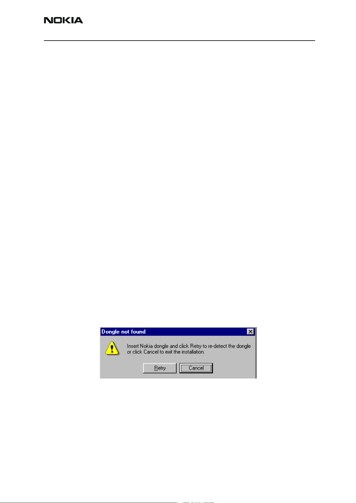
• If at any point during installation you get this message:
“Dongle is not found and installation cannot continue.“
Possible reasons may be a defective or too old PKD-1 dongle (five digit
serial number dongle when used with FPS-8 prommer) or that the FLS4S POS flash dongle is defective or power to it is not supplied by external charger.
First, check the COM /parallel ports used! After correcting the problem,
installation can be restarted.
Installing Phoenix
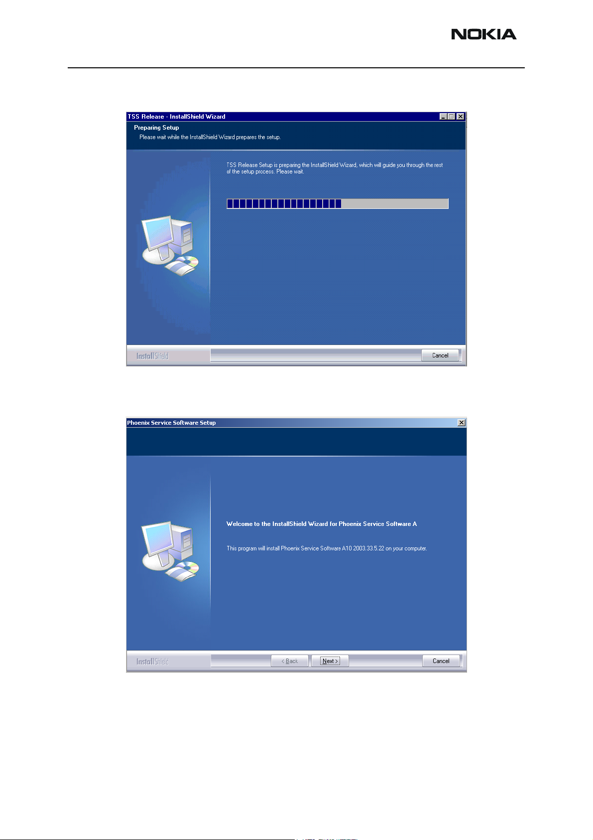
To install Phoenix:
1 Run phoenix_service_sw_a11_2003_41_5_28.exe.
Issue 1 02/04 Copyright ©Nokia. All rights reserved. Page 7
Page 8
RH-26 Company Confidential
5 - Service Software Instructions CCS Technical Documentation
Install Shield starts.
2 In the Welcome dialog, click “Next” to continue.
3 Choose destination folder.
It is recommended to use the default folder C:\ProgramFiles\Nokia\Phoenix.
Page 8 Copyright ©Nokia. All rights reserved. Issue 1 02/04
Page 9
Company Confidential RH-26
CCS Technical Documentation 5 - Service Software Instructions
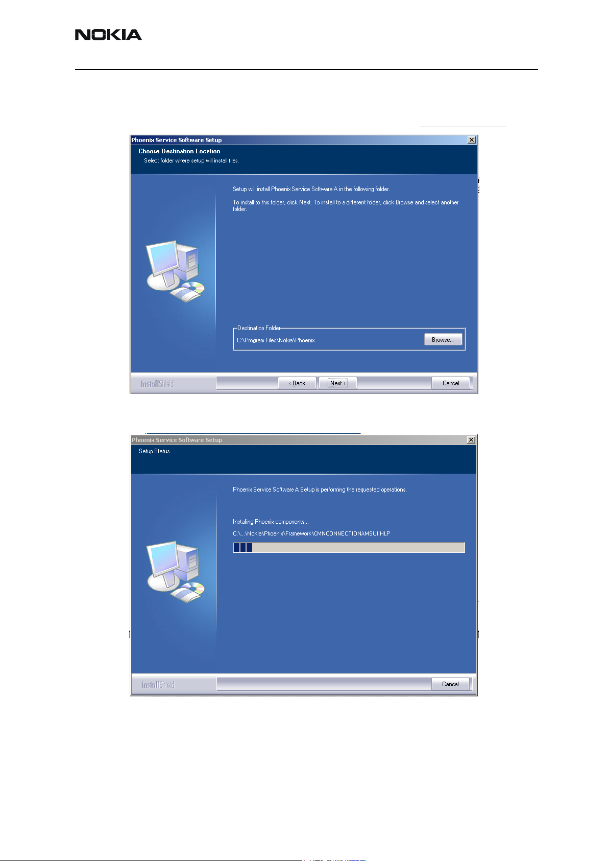
4 To continue, choose “Next”.
You may choose another location by selecting “Browse” (not recommended).
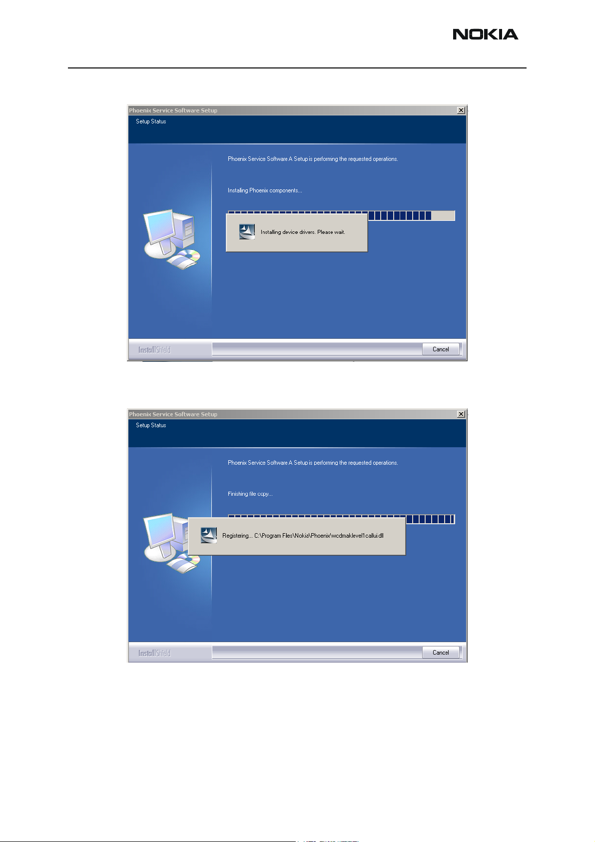
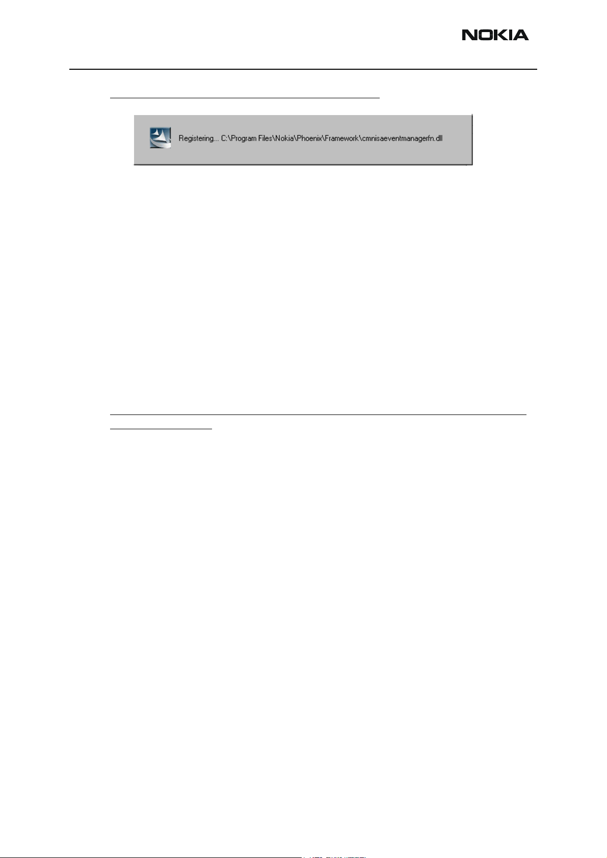
Setup copies the components, progress of the setup is shown. Please wait…
Drivers are installed and updated, please wait. The process may take several min-
Issue 1 02/04 Copyright ©Nokia. All rights reserved. Page 9
Page 10
RH-26 Company Confidential
5 - Service Software Instructions CCS Technical Documentation
utes to complete.
If the operating system does not require rebooting (Windows 2000, XP), the
PC components are registered straight away.
Page 10 Copyright ©Nokia. All rights reserved. Issue 1 02/04
Page 11
Company Confidential RH-26
CCS Technical Documentation 5 - Service Software Instructions
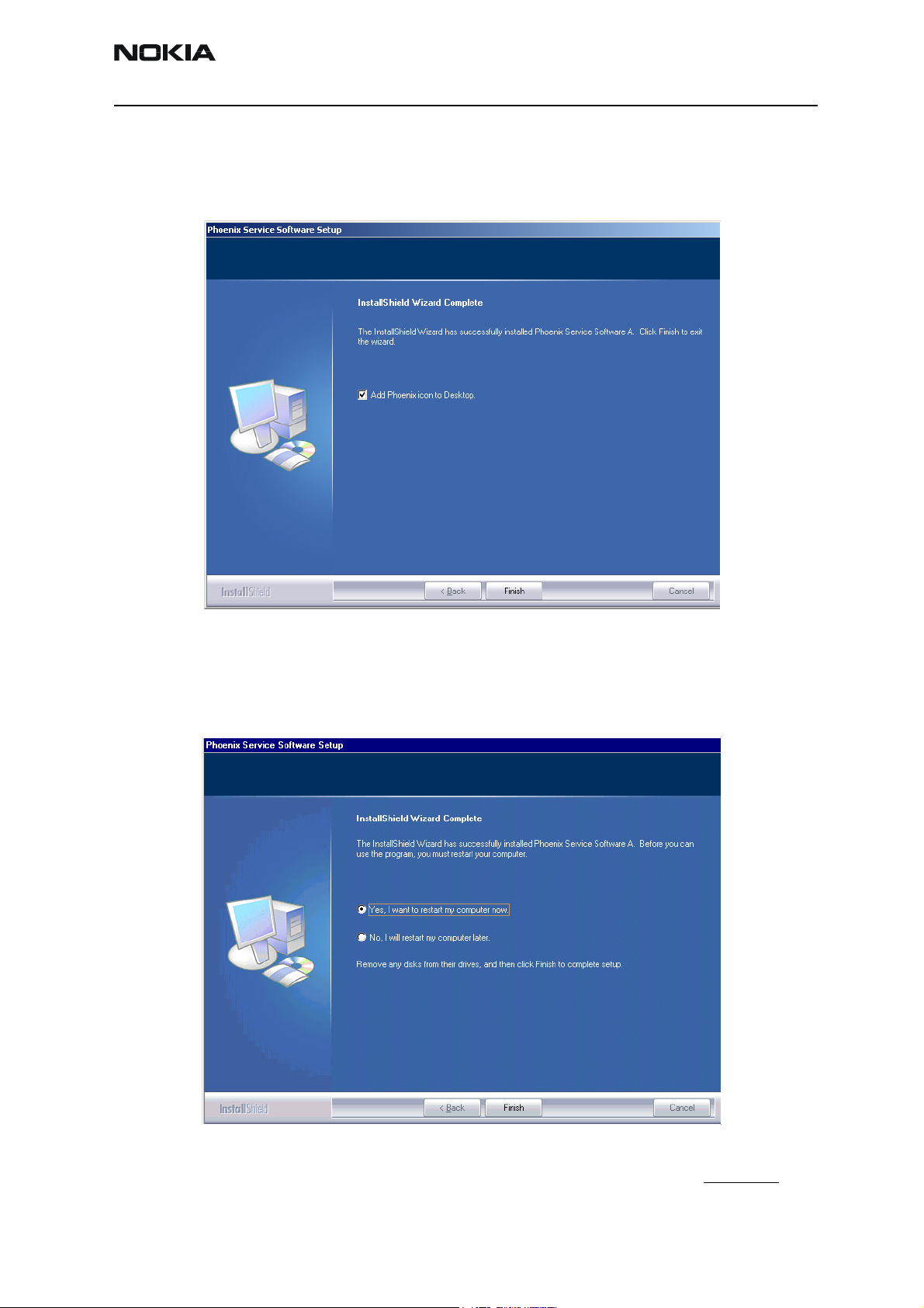
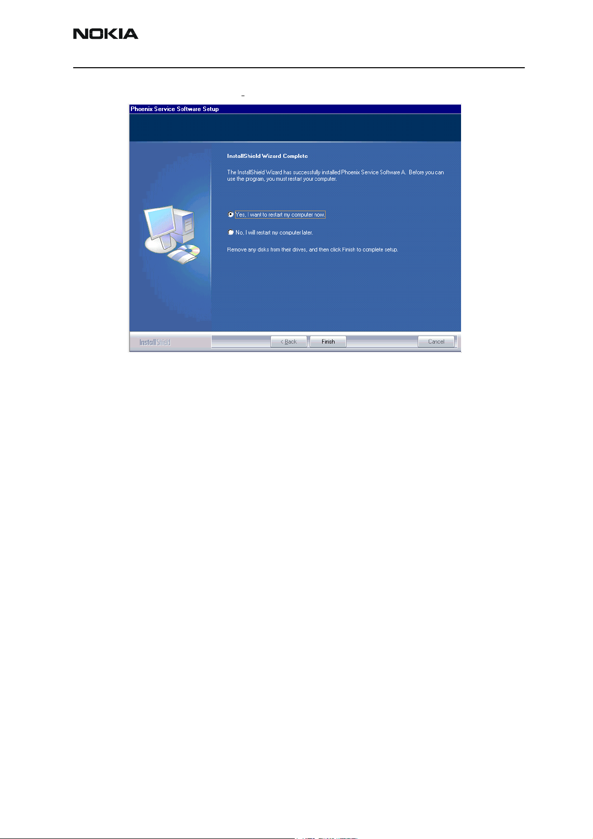
5 Click "Finish".
Phoenix is ready for use.
If the operating system used requires restarting your computer (Windows 98, SE, ME)
the Install Shield Wizard will tell you about it. Select "Yes..." to reboot the PC immediately and "No..." to reboot the PC manually afterwards.
After the reboot, components are registered and Phoenix is ready for use. Note that
Issue 1 02/04 Copyright ©Nokia. All rights reserved. Page 11
Page 12
RH-26 Company Confidential
5 - Service Software Instructions CCS Technical Documentation
Phoenix does not work, if components are not registered.
Now the installation of Phoenix service SW is ready and it can be used after:
• Installing phone model specific data package for Phoenix
• Configuring users and connections
• FLS-4S can be used straight away
• FPS-8* can be used after updating flash update package files
Updating Phoenix installation
If you already have the Phoenix service SW installed on your computer, you will need to
update it when new versions are released.
Always use the latest available versions of both the Phoenix service SW and the phone
specific data package. Instructions can be found in phone model specific Technical Bulletins and phone data package readme.txt files (shown during installation).
To update Phoenix, you need to take exactly the same steps as when installing it for the
first time.
1 Download the installation package to your computer hard disk.
2 Close all other programs.
3 Run the application file (e.g. phoenix_service_sw_a11_2003_41_5_28.exe).
4 Newer version of Phoenix is installed.
5 Driver versions are checked and if need be, updated.
When you update Phoenix (e.g. a10_2003_33_5_22 to a11_2003_41_5_28.exe), the
update takes place automatically without uninstallation.
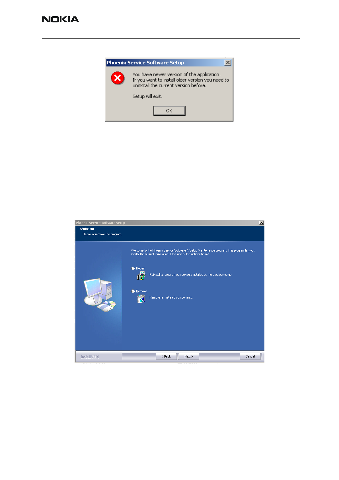
If you try to update Phoenix with the same version that you already have (e.g.
a11_2003_41_5_28 to a11_2003_41_5_28), you are asked if you want to uninstall the
current Phoenix version. In this case you can choose between total uninstallation and
repair.
If you try to install an older version (e.g. downgrade from a11_2003_41_5_28 to
Page 12 Copyright ©Nokia. All rights reserved. Issue 1 02/04
Page 13
Company Confidential RH-26
CCS Technical Documentation 5 - Service Software Instructions
a10_2003_33_5_22), installation will be interrupted.
Please always follow the instructions on the screen.
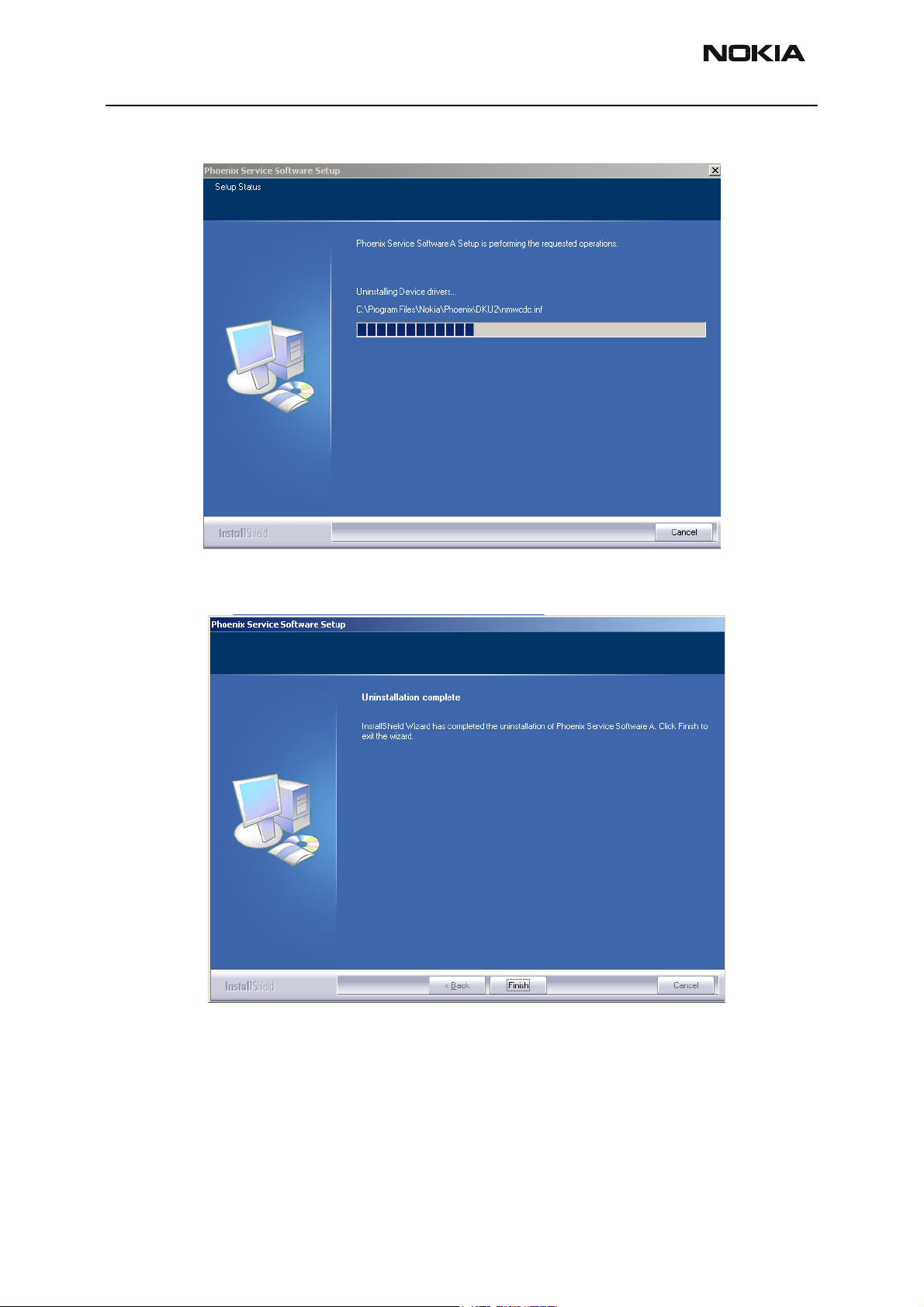
Uninstalling Phoenix
You can uninstall Phoenix manually from Windows’s control panel.
To uninstall:
1 Choose Add / Remove Programs -> “Phoenix Service Software”.
2 Click "Add/Remove" -> “Remove”.
Issue 1 02/04 Copyright ©Nokia. All rights reserved. Page 13
Page 14
RH-26 Company Confidential
5 - Service Software Instructions CCS Technical Documentation
Progress of the uninstallation is shown.
3 If the operating system does not require rebooting, click “Finish” to complete.
If the operating system requires rebooting, Install Shield Wizard notifies you
about it. Select "Yes..." to reboot the PC immediately and "No..." to reboot the PC
Page 14 Copyright ©Nokia. All rights reserved. Issue 1 02/04
Page 15
Company Confidential RH-26
CCS Technical Documentation 5 - Service Software Instructions
manually afterwards.
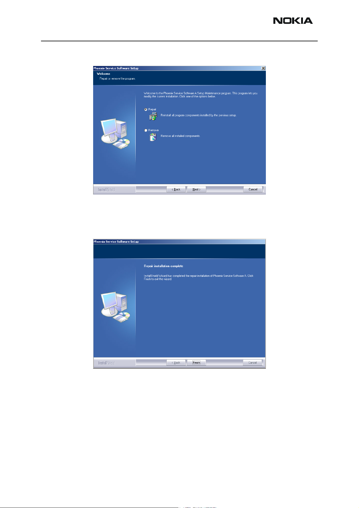
Repair
If you experience any problems with service software or suspect that files have been lost,
you can use the repair function before completely reinstalling Phoenix. Note that the
original installation package (e.g. phoenix_service_sw_a11_2003_41_5_28.exe) must be
found on your PC when you run the repair setup.
To run the repair setup:
1 Run Windows Control Panel.
2 Choose Add / Remove Programs -> “Phoenix Service Software”.
3 Click "Add/Remove".
Issue 1 02/04 Copyright ©Nokia. All rights reserved. Page 15
Page 16
RH-26 Company Confidential
5 - Service Software Instructions CCS Technical Documentation
4 In the following view, choose “Repair”.
Phoenix reinstalls the required components and registers them, procedure is the
same as in the update installation.
5 To complete, choose “Finish”.
Page 16 Copyright ©Nokia. All rights reserved. Issue 1 02/04
Page 17
Company Confidential RH-26
CCS Technical Documentation 5 - Service Software Instructions
Data Package for Phoenix (Product Specific)
Before installation
• Product data package contains all product specific data to make the
Phoenix service software and tools usable with a certain phone model.
• Check that the dongle is attached to the parallel port of your computer.
• Install Phoenix service SW.
• Download the installation package (e.g. RH-
26_dp_v_1.0_MCUSW3_19.exe) to your computer (e.g. C:\TEMP).
• Close all other programs.
• Run the application file (e.g. RH-26_dp_v_1.0_MCUSW3_19.exe) and
follow instructions on the screen.
Please note that very often the Phoenix service SW and the phone specific data package
for Phoenix come in pairs, meaning that certain version of Phoenix can only be used with
certain data package version. Always use the latest available versions. Instructions can
be found in phone model specific Technical Bulletins and readme.txt files of the data
packages.
Installing Phoenix data package (product specific)
To install the data package:
1 Run the RH-26_dp_v_1.0_MCUSW3_19.exe file.
2 Click “Next”.
Issue 1 02/04 Copyright ©Nokia. All rights reserved. Page 17
Page 18
RH-26 Company Confidential
5 - Service Software Instructions CCS Technical Documentation
The files needed for installation are extracted. Please wait…
3 To continue, click “Next”.
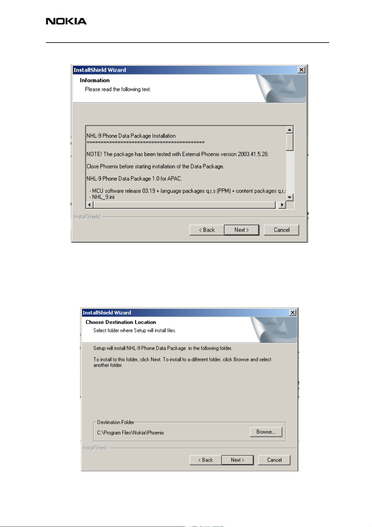
4 From this view, you can see the contents of the data package. Read the text
carefully. There should be information about the Phoenix version needed with
this data package.
Page 18 Copyright ©Nokia. All rights reserved. Issue 1 02/04
Page 19
Company Confidential RH-26
CCS Technical Documentation 5 - Service Software Instructions
5 Click “Next”.
6 To continue, confirm location and click “Next”.
Install shield checks where the Phoenix application is installed and the directory
is shown.
7 To continue, click “Next”.
Issue 1 02/04 Copyright ©Nokia. All rights reserved. Page 19
Page 20
RH-26 Company Confidential
5 - Service Software Instructions CCS Technical Documentation
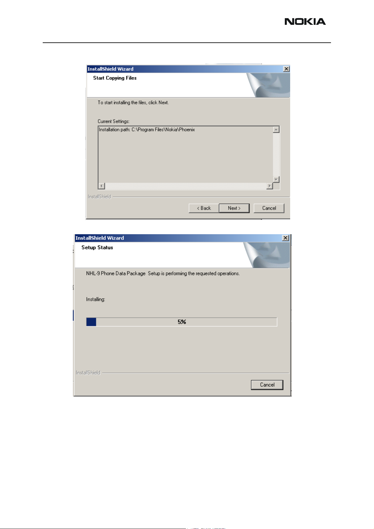
8 To start copying the files, click “Next”.
Phone model specific files are installed. Please wait.
Page 20 Copyright ©Nokia. All rights reserved. Issue 1 02/04
Page 21
Company Confidential RH-26
CCS Technical Documentation 5 - Service Software Instructions
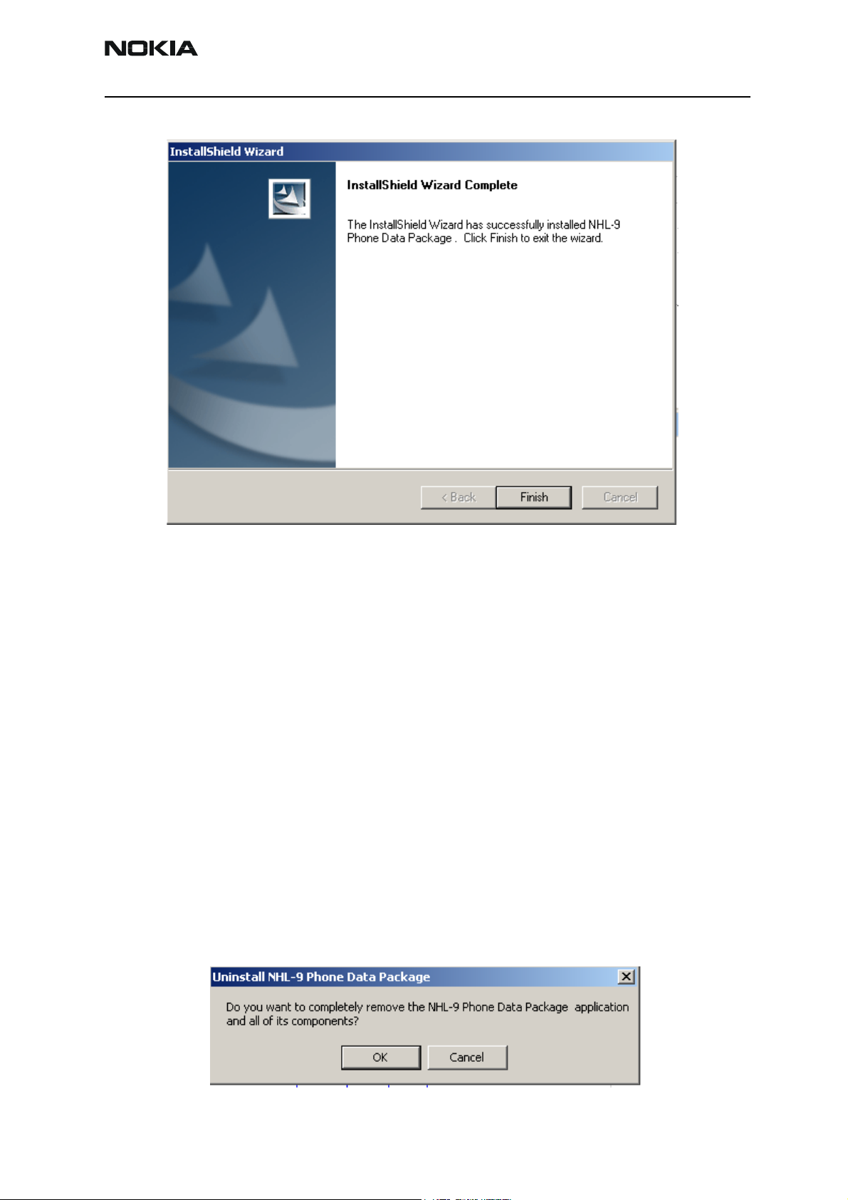
9 To complete installation, click “Finish”.
You now have all phone model specific files installed in your Phoenix service SW.
Now Phoenix can be used to for example flash phones and print type labels after:
• Configuring users
• Managing connections
• FLS-4S can be used right away
• FPS-8* can be used after updating flash update package files to it
Uninstalling the data package
You can also uninstall the data package manually from the Windows’s Control Panel.
1 Choose Add / Remove Programs/ -> RH-26 Phone Data Package.
2 If you try to install the same version of Phoenix data package that you already
have, you are asked if you want to uninstall the current version. Answer “OK” to
uninstall, “Cancel” if you do not want to uninstall.
Issue 1 02/04 Copyright ©Nokia. All rights reserved. Page 21
Page 22
RH-26 Company Confidential
5 - Service Software Instructions CCS Technical Documentation
Older versions of data packages need not be uninstalled unless instructions to do
so are given in the readme.txt of the data package and bulletins concerning the
release. Please read all related documents carefully.
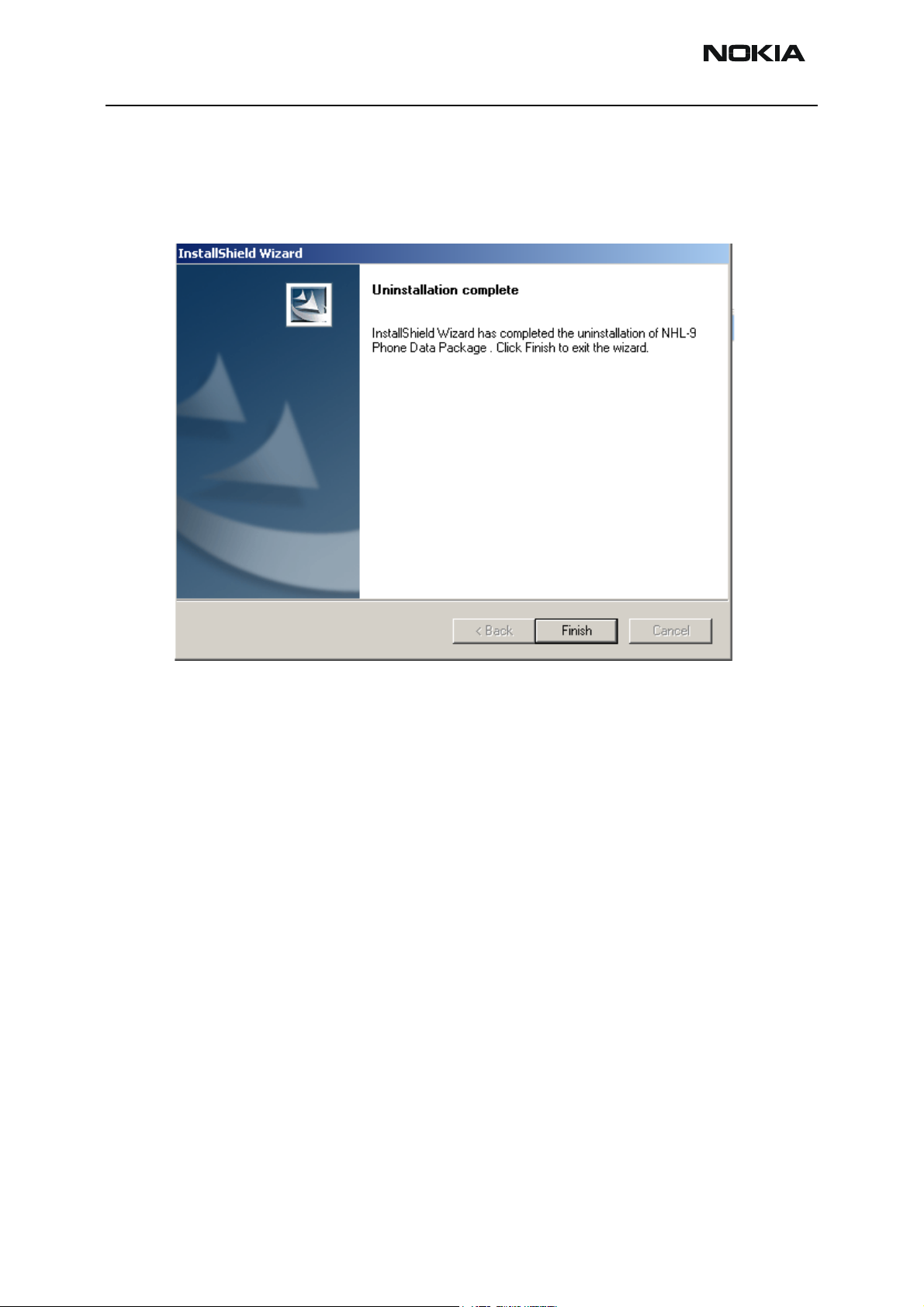
3 Once the previously installed data package is uninstalled, click “Finish”.
4 To continue installation from the beginning, run the RH-
26_dp_v_1.0_MCUSW3_19.exe file gain.
Page 22 Copyright ©Nokia. All rights reserved. Issue 1 02/04
Page 23
Company Confidential RH-26
CCS Technical Documentation 5 - Service Software Instructions
Configuring Users
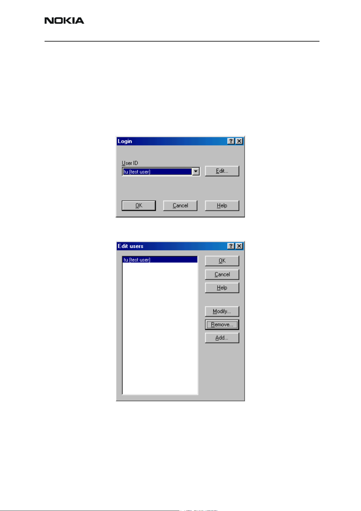
To configure users:
1 Start Phoenix service SW and login.
2 To add new user, choose “Edit”.
If a user ID is already configured, choose your own user ID from the list and click
“OK”.
3 To continue, click “Add”.
Issue 1 02/04 Copyright ©Nokia. All rights reserved. Page 23
Page 24
RH-26 Company Confidential
5 - Service Software Instructions CCS Technical Documentation
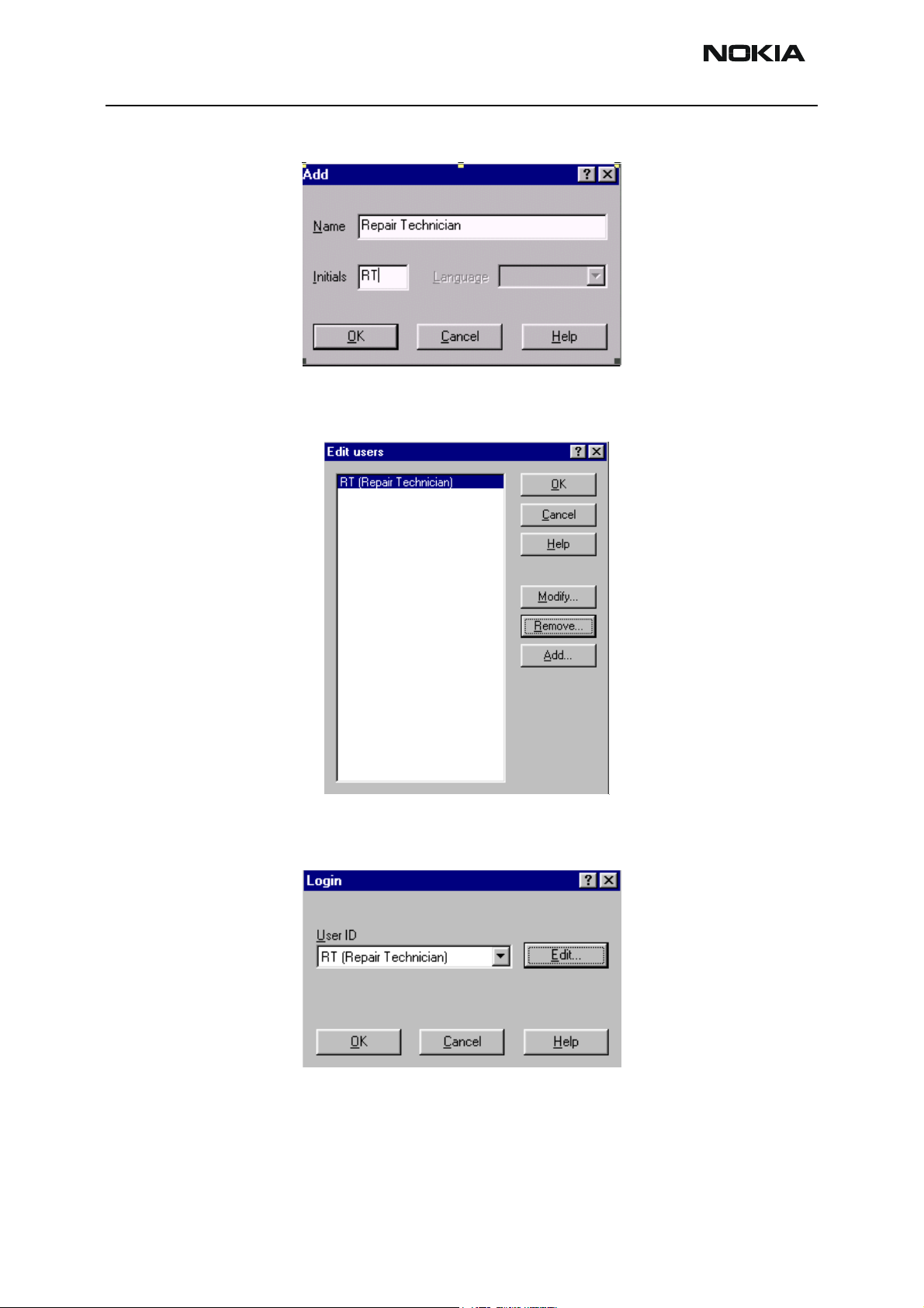
4 Type in your name and initials to the fields and click “OK”.
5 User has now been created, click “OK”.
6 You are now able to login with this username, click “OK”.
Page 24 Copyright ©Nokia. All rights reserved. Issue 1 02/04
Page 25

Company Confidential RH-26
CCS Technical Documentation 5 - Service Software Instructions
Managing Connections
To manage connections:
1 Start Phoenix service SW and login.
2 From the File menu, choose “Manage Connections”.
The following dialog appears:
In the Manage Connections dialog, you can select, edit, delete existing connections and create new ones.
You can create a connection either manually or by using a Connection Wizard.
Issue 1 02/04 Copyright ©Nokia. All rights reserved. Page 25
Page 26

RH-26 Company Confidential
5 - Service Software Instructions CCS Technical Documentation
3 To add new connection, click “Add” and select if you want to create it manually
or by using the Wizard.
4 To continue, click “Next”.
5 In the next dialogs, you are asked to select some settings for the connection.
Manual settings
A) For FLS-4S POS Flash Device, choose the following connection settings:
Media: FBUS
COM Port: Virtual COM Port used by FLS-4 Please always check this!
(To check the settings, go to Windows / Control Panel / FLS Virtual Port / Configuration)
B) For FPS-8 Flash Prommer, choose the following connection settings:
Media: FPS-8
Port Num: COM Port where FPS-8 is connected
COMBOX_DEF_MEDIA: FBUS
6 To complete, click “Finish”.
If you use the Wizard, connect the tools and the phone to your PC and the wizard
Page 26 Copyright ©Nokia. All rights reserved. Issue 1 02/04
Page 27

Company Confidential RH-26
CCS Technical Documentation 5 - Service Software Instructions
will automatically try to configure the correct connection.
7 To activate the connection you want to use, click it and use up/down arrows to
move it on top of the list.
8 Click “Apply”.
The connection is now selected and can be used after closing the “Manage Connections” window.
The selected connection is shown at the right-hand bottom corner of the screen.
9 To use the selected connection, connect the phone to Phoenix with correct ser-
vice tools, make sure that it is switched on. From the File menu, choose “Scan
Product”.
When a product is found, Phoenix loads product support and when everything is
ready, name of the loaded product support module and its version are shown at
Issue 1 02/04 Copyright ©Nokia. All rights reserved. Page 27
Page 28

RH-26 Company Confidential
5 - Service Software Instructions CCS Technical Documentation
the bottom of the screen.
Page 28 Copyright ©Nokia. All rights reserved. Issue 1 02/04
Page 29

Company Confidential RH-26
CCS Technical Documentation 5 - Service Software Instructions
Updating Flash Support Files for FPS-8* and FLS-4*
Before installation
• Install Phoenix service SW.
• Install phone model specific data package for Phoenix.
• The flash support files are delivered in the same installation package
with Phoenix data packages or newer Phoenix packages beginning
from September 2003.
• Normally it is enough to install Phoenix and phone’s data package
because the Phoenix installation always includes the latest flash update
package files for FLS-4S / FPS-8*.
• Separate installation package for flash support files is available, and the
files can be updated by following these instructions (if updates appear
between Phoenix / data package releases).
Installing the flash support files (only separate installation package)
If you are not using a separate installation package, you can skip this section.
To install the support files:
10 Double click flash_update_03_05_001.exe.
If the same version of the flash update package already exists, and you want to
reinstall it, the previous package is first uninstalled. Restart installation again
Issue 1 02/04 Copyright ©Nokia. All rights reserved. Page 29
Page 30

RH-26 Company Confidential
5 - Service Software Instructions CCS Technical Documentation
after that.
If you try to downgrade the existing version, the setup will be aborted. However,
if you want to downgrade, uninstall newer files manually from the Control Panel
and then rerun the installation again.
If an older version exists on your PC and it needs to be updated, click “Next” to
continue installation.
11 Choose destination location.
It is highly recommended to install the files to the default destination folder
C:\Program Files\Nokia\Phoenix.
Note! When installing the flash update files for the first time you may choose
Page 30 Copyright ©Nokia. All rights reserved. Issue 1 02/04
Page 31

Company Confidential RH-26
CCS Technical Documentation 5 - Service Software Instructions
another location by selecting “Browse” (not recommended).
12 To continue, click “Next”.
The installation continues…
Issue 1 02/04 Copyright ©Nokia. All rights reserved. Page 31
Page 32

RH-26 Company Confidential
5 - Service Software Instructions CCS Technical Documentation
13 To complete the procedure, click “Finish”.
FLS-4 can be used right after the flash update package is installed.
FPS-8* flash prommer must be updated by using Phoenix!
Updating FPS-8* flash prommer SW
To update the flash prommer software:
1 Start Phoenix service software and login.
Manage connection correctly for the FPS-8* flash prommer.
2 From the “Flashing” menu, choose ”FPS-8 Maintenance”.
3 When a new FPS-8 flash update package is installed to your computer, you are
asked to update the files to your FPS-8 Prommer.
Page 32 Copyright ©Nokia. All rights reserved. Issue 1 02/04
Page 33

Company Confidential RH-26
CCS Technical Documentation 5 - Service Software Instructions
To update files, click “Yes”.
The update procedure takes a couple of minutes, please wait until you are notified that the update has been successful.
4 Click “OK” and close the “FPS-8 Maintenance” window.
View after successful prommer software update.
Issue 1 02/04 Copyright ©Nokia. All rights reserved. Page 33
Page 34

RH-26 Company Confidential
5 - Service Software Instructions CCS Technical Documentation
You can also update FPS-8 sw by pressing the ”Update” button and selecting the appropriate fps8upd.ini file from the C:\Program Files\Nokia\Phoenix\Flash directory
All files can be loaded separately to FPS-8. To do this, just press the right mouse button
in the ”Flash box files” window and select the desired file type. More information and
help can be found from the “Help” dialog.
Page 34 Copyright ©Nokia. All rights reserved. Issue 1 02/04
Page 35

Company Confidential RH-26
CCS Technical Documentation 5 - Service Software Instructions
Activating and Deactivating FPS-8
Before the FPS-8 can be successfully used for phone programming, it must be first activated.
If there is a need to send the FPS-8 box to somewhere, e.g. for repair, the box must be
first deactivated.
Activating FPS-8
To activate FPS-8:
1 First, fill in the “FPS-8 activation request” sheet included in the FPS-8 sales pack-
age and follow the instructions given in the sheet.
2 When you have received the activation file (e.g. 00000.in), copy it to C:\Program-
Files\Nokia\Phoenix\BoxActivation directory (this directory is created when Phoenix is installed).
3 Start Phoenix service software.
4 From the “Flashing” menu, choose ”FPS-8 maintenance”.
5 In the “FPS-8 Maintenance” window, click “Activate”.
6The activation file you saved to C:\ProgramFiles\Nokia\Phoenix\BoxActivation is
Issue 1 02/04 Copyright ©Nokia. All rights reserved. Page 35
Page 36

RH-26 Company Confidential
5 - Service Software Instructions CCS Technical Documentation
displayed (e.g. 00000.in), check that it is correct.
7 To activate the box, click “Open”.
8 To complete the activation, turn FPS-8 power off and on.
Deactivating FPS-8
To deactivate FPS-8:
1 Start Phoenix service software.
2 From the “Flashing” menu, choose ”FPS-8 Maintenance”.
3 In the “FPS-8/8C Maintenance” window, click “Deactivate”.
4 To confirm deactivation, click “Yes”.
The box is deactivated.
5 To complete deactivation, turn FPS-8 power off and on.
Page 36 Copyright ©Nokia. All rights reserved. Issue 1 02/04
Page 37

Company Confidential RH-26
CCS Technical Documentation 5 - Service Software Instructions
JBV-1 Docking Station SW
The JBV-1 docking station is a common tool for all DCT-4 generation products. In order
to make the JBV-1 usable with different phone models, a phone specific docking station
adapter is used for different service functions.
The JBV-1 docking station contains software (firmware) which can be updated.
You need the following equipment to be able to update JBV-1 software:
• PC with USB connection
• Operating System supporting USB (Not Win 95 or NT)
• USB cable (can be purchased from shops or suppliers providing PC
hardware and accessories)
• JBV-1 docking station
• External power supply 11-16V
Before installation
Download the Jbv1_18_update.zip file to your computer (e.g. C:\TEMP) from your download web site.
Close all other programs.
Follow instructions on the screen.
Installing SW needed for the JBV-1 SW update
Note: DO NOT CONNECT THE USB CABLE / JBV-1 TO YOUR COMPUTER YET!
To install the needed SW:
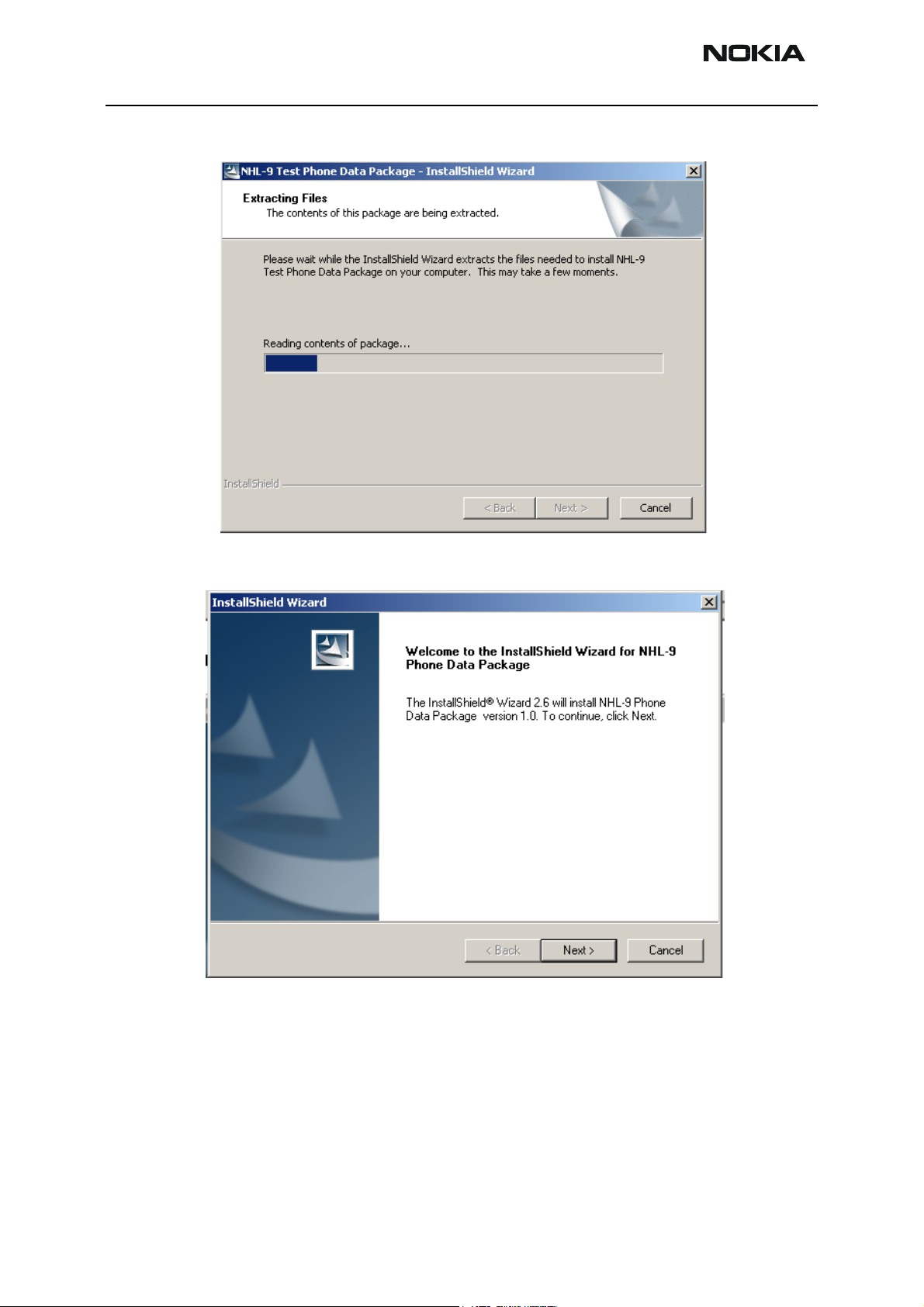
1 To run the Jbv1_18_update.zip file, double click “Setup.exe”.
Files needed for JBV-1 package setup program are extracted.
Installation begins, please read the information displayed.
Issue 1 02/04 Copyright ©Nokia. All rights reserved. Page 37
Page 38

RH-26 Company Confidential
5 - Service Software Instructions CCS Technical Documentation
2 To continue, click “Next”.
3 Use the suggested destination folder where JBV-1 SW package is installed and
click “Next” to continue.
Page 38 Copyright ©Nokia. All rights reserved. Issue 1 02/04
Page 39

Company Confidential RH-26
CCS Technical Documentation 5 - Service Software Instructions
4 To continue, select “Full” and click “Next”.
The program folder is created.
5 To continue, click “Next”.
Software files are installed.
Issue 1 02/04 Copyright ©Nokia. All rights reserved. Page 39
Page 40

RH-26 Company Confidential
5 - Service Software Instructions CCS Technical Documentation
6 After successful installation, click “Finish” to complete.
7 Connect the USB cable / JBV-1 to your computer.
8 Connect power to JBV-1 (11-16V DC) from external power supply, then connect
USB cable between JBV-1’s USB connector and PC.
9 Install or update the JBV-1 USB drivers which are delivered with the JBV-1 SW
installation package. They can be found in folder:
C:\Program Files\Nokia\ JBV-1 Firmware Update\JBV-1USB driver
If there is no previously installed JBV-1 firmware update package installed on
your computer, Windows detects the connected USB cable and drivers for the
new HW. Please follow the instructions and allow Windows to search and install
the best drivers available.
If there is a previously installed JBV-1 firmware update package ( v 17 or older)
on your computer, please update the JBV-1 USB driver. Please see the readme.txt
file under:
C:\Program Files\Nokia\ JBV-1 Firmware Update\JBV-1USB driver
for instructions on how to update the JBV-1 USB driver.
After you have installed or updated the JBV-1 USB driver, the actual JBV-1 SW
update begins.
10 Go to folder C:\Program Files\Nokia\JBV-1 Firmware Update\JBV-1 Firmware
Update.
Page 40 Copyright ©Nokia. All rights reserved. Issue 1 02/04
Page 41

Company Confidential RH-26
CCS Technical Documentation 5 - Service Software Instructions
11 To start JBV-1 SW update, double click fwup.exe.
JBV-1 firmware update starts and shows the current status of the connected
JBV-1.
If the firmware version read from your JBV-1 is not the latest one available ( v. 17
or older), it needs to be updated to version 18. To do this, click “Update Firmware”.
If you simply want to check the SW version, click “Refresh Status”.
12 To update your JBV-1 to the latest version 18, choose file JBV1v18.CDE and
“Open”.
Please wait, it takes a while until you can hear a “click” from the JBV-1.
The older sw file JBV1v17.CDE is visible in this view only if the previous JBV-1 SW
package has been installed on your computer.
13 Click “OK”.
Issue 1 02/04 Copyright ©Nokia. All rights reserved. Page 41
Page 42

RH-26 Company Confidential
5 - Service Software Instructions CCS Technical Documentation
After a successful update and after choosing “OK” the current JBV-1 status is
displayed
You have now updated the JBV-1 software and it is ready for use.
If you have several docking stations you need to update, disconnect the power & USB
cables from the previous one and connect them to the next docking station.
After you have updated all docking stations, close the “JBV-1 Firmware Update” dialog.
Page 42 Copyright ©Nokia. All rights reserved. Issue 1 02/04
Page 43

Company Confidential RH-26
CCS Technical Documentation 5 - Service Software Instructions
Quick Guide for Tuning RH-26* with Phoenix
RF tunings should be made in the same order as shown in this document. The order of
the corresponding menu items in the Phoenix service SW may be different.
If baseband tunings are needed, they should be made before the RF tunings.
Avoid unnecessary tuning; factory-tuning values are always the most accurate ones.
Views in this document may change as the service software is developed. Please refer to
the Phoenix help files, phone model specific service manual and bulletins for help.
Issue 1 02/04 Copyright ©Nokia. All rights reserved. Page 43
Page 44

RH-26 Company Confidential
5 - Service Software Instructions CCS Technical Documentation
Service Tool Concept for Baseband Tunings
EM calibrations should be carried out in the JBV-1 docking station equipped with the
DA-6 docking station adapter.
Note: RF tunings must be carried out in MJ-5 module jig,
Power to JBV-1 should be supplied from an external DC power supply, not from the FPS8 prommer.
JBV-1 input voltages:
• Maximum + 16 VDC
• Nominal input for RF tunings is +12 V DC
• Maximum input voltage is 16 V DC, nominal input for tunings is +12V
DC.
Item Service accessory Type Product code
1 JBV-1 Docking station 0770298
Page 44 Copyright ©Nokia. All rights reserved. Issue 1 02/04
Page 45

Company Confidential RH-26
CCS Technical Documentation 5 - Service Software Instructions
Item Service accessory Type Product code
2 DA-6 Docking station adapter 0770653
3 SCB-3 DC-DC cable 0730114
4 XRF-1 Antenna cable 0730085
5 PCS-1 DC power cable 0730012
6 DAU-9S Service MBUS cable 0730108
7 PKD-1 Software protection key (Dongle) 0750018
8 SW
Issue 1 02/04 Copyright ©Nokia. All rights reserved. Page 45
Page 46

RH-26 Company Confidential
5 - Service Software Instructions CCS Technical Documentation
Baseband Tunings
Energy management tuning
External power supply is needed.
EM calibration is used for calibrating battery and charger settings of the phone.
To calibrate:
1 Connect the DC Cable SCB-3 between JBV-1 and the Vin of phone for charger
calibration.
2 Connect 12…15 V from power supply to JBV-1.
NOTE! Check that connection is F-BUS (does not work with M-BUS!).
3 From the “Tuning” menu, choose “Energy Management Calibration”.
Energy Management values to be calibrated are checked.
4 To show current values in the phone and to check that the communication works,
click “Read From Phone”.
Page 46 Copyright ©Nokia. All rights reserved. Issue 1 02/04
Page 47

Company Confidential RH-26
CCS Technical Documentation 5 - Service Software Instructions
5 To run the selected calibrations, click “Calibrate”.
Min Max
ADC gain 25400 29000
ADC offset -100 100
BSI gain 860 1180
BTEMP gain 1980 2280
VBAT gain 10000 11000
VBAT offset 2300 2700
VCHAR 58500 62000
ICHAR 3850 4650
6 If values shown are within limits, click “Save To Phone” to save values to phone.
NOTE! Only values of the checked tunings (battery size, battery temperature etc.)
are saved.
7 To end tuning, close the “Energy Management Calibration” dialog.
Tuning LCD contrast
External equipment is not needed.
This function is used to calibrate the LCD contrast.
Issue 1 02/04 Copyright ©Nokia. All rights reserved. Page 47
Page 48

RH-26 Company Confidential
5 - Service Software Instructions CCS Technical Documentation
Tuning is necessary only if there is considerable difference in the contrast or appearance
of the LCD after, for example, replacing the LCD module.
To tune the LCD contrast:
1 From the “Testing” menu, choose “Display Tune”.
2 To tune the display contrast, use the sliders.
3 To end tuning, close the “Display Tune” dialog.
Page 48 Copyright ©Nokia. All rights reserved. Issue 1 02/04
Page 49

Company Confidential RH-26
CCS Technical Documentation 5 - Service Software Instructions
Service Tool Concept for RF Tunings
All RF tunings for RH-26* phones must be carried out in the MJ-5 module jig.
Power to MJ-5 should be supplied from an external DC power supply, not from the FPS-8
prommer.
MJ-5 input voltages:
• Maximum input voltage is +12 VDC
• Nominal input for RF tunings is +8V DC.
Remember cable attenuation when setting the required RF levels.
NOTE! RF tunings should be made in the same order as shown in this document. The order of the
corresponding menu items in the Phoenix service software may be different.
Item Type Description Product code
1 MJ-5 Module jig 0770651
2 PCS-1 DC power cable 0730012
3 XRF-1 RF antenna cable 0730085
4 DAU-9S Service MBUS cable 0730108
5 PKD-1 Software protection key (Dongle) 0750018
6 SW
Issue 1 02/04 Copyright ©Nokia. All rights reserved. Page 49
Page 50

RH-26 Company Confidential
5 - Service Software Instructions CCS Technical Documentation
[This page intentionally blank]
Page 50 Copyright ©Nokia. All rights reserved. Issue 1 02/04
Page 51
Company Confidential RH-26
CCS Technical Documentation 5 - Service Software Instructions
Receiver Tunings
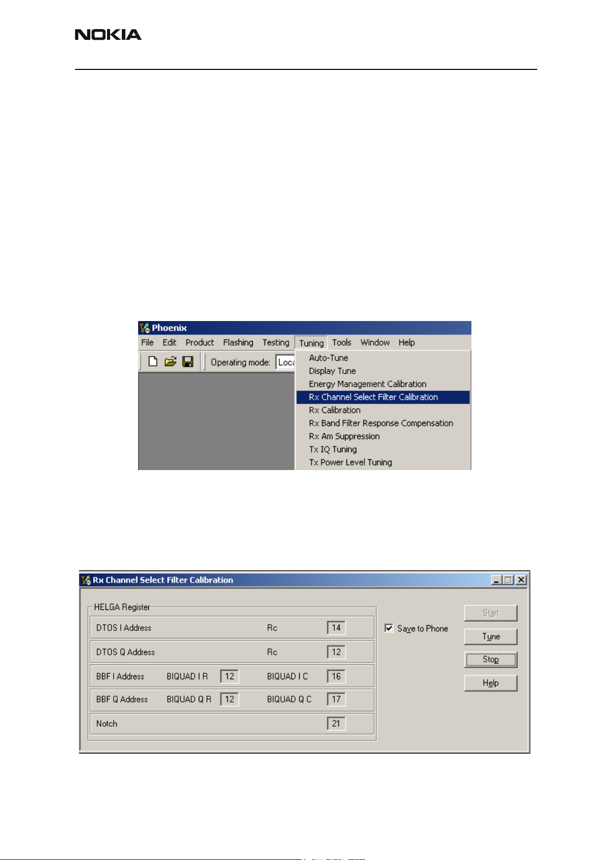
Calibrating RX channel select filter
Extra equipment or an external RF signal is not needed.
Must be done before other RX calibrations.
This function is used to calibrate RX channel select filter in GSM phones.
Rx channel select filter is tuned only in one (lowest) band, meaning that there is only
single calibration for all bands.
To calibrate:
1 From the “Tuning” menu, choose Rx Channel Select Filter Calibration.
Values are saved to phone when the “Save to Phone” check box is checked. If the
“Save to Phone” check box is unchecked, the values are not saved to the phone
when you stop the tuning or exit the dialog.
2 To start the tuning, click “Tune".
Tuning values should be 0…31.
Issue 1 02/04 Copyright ©Nokia. All rights reserved. Page 51
Page 52

RH-26 Company Confidential
5 - Service Software Instructions CCS Technical Documentation
3 click “Stop”.
4 To end tuning, close the “RX Channel Select Filter Calibration“ dialog.
RX calibration
RF generator is needed.
This tuning performs RX calibration.
Must be done separately on all bands!
RX calibration is done first at EGSM (GSM850), then continues at the GSM1800 band
and finally ends at the GSM1900 band.
AFC tuning is done while EGSM (GSM850) band RX calibration is performed.
Remember to take jig and cable attenuations into account!
To calibrate:
1 From the “Tuning” menu, choose Rx Calibration.
Calibrating EGSM850 band
2 To begin, click “Start”.
Page 52 Copyright ©Nokia. All rights reserved. Issue 1 02/04
Page 53

Company Confidential RH-26
CCS Technical Documentation 5 - Service Software Instructions
3 Set RF generator to required EGSM850 frequency => OK.
Tuning values and ADC readings are displayed.
Typical values and limits in (GSM850) RX Calibration:
EGSM (GSM850) Typical value Limits
AFC value -90 -350…+350
AFC slope 270 150…350
RSSI0 65.09375 58…68
RSSI1 71.09375 64…74
RSSI2 76.96025 70…80
RSSI3 82.90625 76…86
RSSI4 88.90625 82…92
RSSI5 93.71875 88…98
RSSI6 99.71875 94…104
RSSI7 105.53125 100…110
R S SI 8 111 . 53 1 25 1 06 … 11 6
RSSI9 117.53125 112…122
RSSI10 123.53125 118…128
RSSI11 129.53125 124…134
RSSI12 135.53125 130…140
RSSI13 141.53125 136…146
RSSI14 147.53125 142…152
4 Tuning moves automatically to the next band (GSM1800), when you click “Save
& Continue”.
Issue 1 02/04 Copyright ©Nokia. All rights reserved. Page 53
Page 54

RH-26 Company Confidential
5 - Service Software Instructions CCS Technical Documentation
Calibrating GSM1800 band
5 When asked, set RF generator to the required GSM 1800 frequency => OK.
Tuning values and ADC readings are displayed.
Typical values and limits in (GSM1800) RX Calibration:
GSM1800 Typical value Limits
RSSI0 62.40625 58…68
RSSI1 68.40625 64…74
RSSI2 74.265625 70…80
RSSI3 80.265625 76…86
RSSI4 86.265625 82…92
RSSI5 91.859375 88…98
RSSI6 97.859375 94…104
RSSI7 103.71875 100…110
RSSI8 109.71875 106…116
RSSI9 115.71875 112…122
RSSI10 121.71875 118…128
RSSI11 127.71875 124…134
RSSI12 133.71875 130…140
RSSI13 139.71875 136…146
RSSI14 145.71875 142…152
6 Tuning automatically continues to the next band (GSM1900) when you click
“Save & Continue”.
Page 54 Copyright ©Nokia. All rights reserved. Issue 1 02/04
Page 55

Company Confidential RH-26
CCS Technical Documentation 5 - Service Software Instructions
Calibrating GSM1900 band
7 Set RF generator to required GSM1900 frequency => OK.
Tuning values and ADC readings are displayed.
Typical values and limits in (GSM1900) RX Calibration:
GSM1900 Typical value Limits
RSSI0 66.25 61…71
RSSI 72.25 67…77
RSSI2 78.09375 73…83
RSSI3 84.09375 79…89
RSSI4 90.09375 85…95
RSSI5 93.25 88…98
RSSI6 99.25 94…104
RSSI7 105.09375 100…110
RSSI8 111.09375 106…116
RSSI9 117.09375 112…122
RSSI1 123.09375 118…128
RSSI11 129.09375 124…134
RSSI12 135.09375 130…140
RSSI13 141.09375 136…146
RSSI14 147.09375 142…152
8 To complete tuning, click “Save & Continue”.
Issue 1 02/04 Copyright ©Nokia. All rights reserved. Page 55
Page 56

RH-26 Company Confidential
5 - Service Software Instructions CCS Technical Documentation
9 To end tuning, close the “RX Calibration” dialog.
RX band filter response compensation
RF generator is needed.
Must be done separately on all bands!
Start RX calibration at EGSM (GSM850), then continue at GSM1800 band and finally at
the GSM1900 band.
Remember to do RX calibration before doing Rx band filter response compensation!
Remember to take jig and cable attenuations into account!
To calibrate:
1 From the “Tuning” menu, choose “Rx Band Filter Response Compensation”.
2 Select "Manual tuning" and click “Start”.
You are asked to supply 9 different RF frequencies to the phone on each band.
Page 56 Copyright ©Nokia. All rights reserved. Issue 1 02/04
Page 57

Company Confidential RH-26
CCS Technical Documentation 5 - Service Software Instructions
The tuning begins from the EGSM850 band and continues the same way for the
GSM1800 and GSM1900 bands.
EGSM850 band
3 Set first required frequency and level => OK.
4 Set 2nd required frequency and level => OK.
5 Set 3rd required frequency and level => OK.
Issue 1 02/04 Copyright ©Nokia. All rights reserved. Page 57
Page 58

RH-26 Company Confidential
5 - Service Software Instructions CCS Technical Documentation
6 Set 4th required frequency and level => OK.
7 Set 5th required frequency and level => OK.
8 Set 6th required frequency and level => OK.
9 Set 7th required frequency and level => OK.
Page 58 Copyright ©Nokia. All rights reserved. Issue 1 02/04
Page 59

Company Confidential RH-26
CCS Technical Documentation 5 - Service Software Instructions
10 Set 8th required frequency and level => OK.
11 Set 9th required frequency and level => OK.
Tuning values and ADC readings are displayed.
Typical values and limits in Rx Band Filter Response Compensation
EGSM850:
Channel Input frequency (MHz) Measured level difference (dB) Limits (dB)
965 923.26771 -1.266 -10…+3.5
975 925.26771 -0.641 -3.5…+3.5
987 927.66771 -0.188 -3.5…+3.5
1009 932.06771 -0.094 -3.5…+3.5
37 942.46771 -0.188 -3.5…+3.5
90 953.06771 0.391 -3.5…+3.5
114 957.86771 -0.266 -3.5…+3.5
124 959.86771 -0.359 -3.5…+3.5
136 962.26771 -0.453 -10…+3.5
12 Tuning continues automatically in the next band (GSM1800) when you click
“Save & Continue”.
Issue 1 02/04 Copyright ©Nokia. All rights reserved. Page 59
Page 60

RH-26 Company Confidential
5 - Service Software Instructions CCS Technical Documentation
GSM1800 band
13 Repeat the same steps as for the EGSM850 band above.
Typical values and limits in Rx Band Filter Response Compensation
GSM1800:
Channel Input frequency (MHz) Measured level difference (dB) Limits (dB)
497 1802.26771 -1.578 -10…+3.5
512 1805.26771 -1.281 -3.5…+3.5
535 1809.86771 -1.188 -3.5…+3.5
606 1824.06771 -0.422 -3.5…+3.5
700 1842.86771 -0.125 -3.5…+3.5
791 1861.06771 0.016 -3.5…+3.5
870 1876.86771 0.094 -3.5…+3.5
885 1879.86771 0.016 -3.5…+3.5
908 1884.46771 -0.047 -10…+3.5
14 Tuning continues automatically in the next band (GSM1900) when you click
GSM1900 band
15 Repeat the same steps as for the EGSM850 and GSM1800 bands above.
Channel Input frequency (MHz) Measured level difference (dB) Limits (dB)
496 1927.06771 -1.547 -10…+3.5
512 1930.26771 -0.625 -3.5…+3.5
537 1935.26771 -0.406 -3.5…+3.5
586 1945.06771 0.219 -3.5…+3.5
661 1960.06771 -0.188 -3.5…+3.5
“Save & Continue”.
Typical values and limits in Rx Band Filter Response Compensation
GSM1900:
736 1975.06771 -0.188 -3.5…+3.5
794 1986.66771 -0.75 -3.5…+3.5
810 1989.86771 -0.875 -3.5…+3.5
835 1994.86771 -1 -10… +3.5
Page 60 Copyright ©Nokia. All rights reserved. Issue 1 02/04
Page 61

Company Confidential RH-26
CCS Technical Documentation 5 - Service Software Instructions
16 To complete tuning, click “Save & Continue”.
17 To end tuning, close the “RX Band Filter Response Compensation” dialog.
RX AM suppression
RF generator is needed (AM modulation).
Must be done separately on all bands!
Start RX calibration at EGSM (GSM850), then at GSM1800 band and finally at the
GSM1900 band.
This tuning dialog performs RX AM suppression tuning.
Remember to take jig and cable attenuations into account!
To calibrate:
1 From the “Tuning” menu, choose “Rx Am Suppression”.
2 Set RF signal generator to correct settings displayed on the left-hand side win-
dow.
Issue 1 02/04 Copyright ©Nokia. All rights reserved. Page 61
Page 62

RH-26 Company Confidential
5 - Service Software Instructions CCS Technical Documentation
3 To begin tuning, click “Start”.
EGSM850 band
4 Set the required frequency and level => OK.
Rx Am Suppression values received from DSP are displayed in the center part of
the window.
Rssi level value displayed at the left bottom part of the window.
One "I" and "Q" line values should be 0, other values 0..31.
RSSI value results vary typically between -88 dBm…-111 dBm at EGSM850,
Page 62 Copyright ©Nokia. All rights reserved. Issue 1 02/04
Page 63

Company Confidential RH-26
CCS Technical Documentation 5 - Service Software Instructions
GSM1800 and GSM1900 bands.
5 Tuning automatically continues in the next band (GSM 1800) when you click
“Save & Continue”.
GSM1800 band
6 Repeat the same steps as for the EGSM850 band above.
7 Tuning automatically continues in the next band (GSM 1800) when you click
GSM1900 band
8 Repeat the same steps as for the EGSM850 and GSM1800 bands.
9 To complete tuning, click “Save & Continue”.
Tuning values and ADC readings are displayed.
“Save & Continue”.
Tuning values and ADC readings are displayed.
10 To end tuning, close the “Rx AM Suppression” dialog.
Issue 1 02/04 Copyright ©Nokia. All rights reserved. Page 63
Page 64

RH-26 Company Confidential
5 - Service Software Instructions CCS Technical Documentation
Transmitter Tunings
TX I/Q tuning
Spectrum analyzer is needed.
With the help of Tx IQ tuning, you can change the Tx I DC offset, Tx Q DC offset, amplitude difference and phase difference.
Must be done separately on all bands!
TX I/Q tuning steps are:
• EGSM (GSM850) with EDGE off
• EGSM with EDGE on,
• GSM1800 with EDGE off
• GSM1800 with EDGE on
• GSM1900 with EDGE off
• GSM1900 with EDGE on
Remember to take jig and cable attenuations into account!
To start tuning:
1 From the “Tuning” menu, choose “TX IQ Tuning”.
EGSM850 band with EDGE Off
2 To begin tuning at EGSM 850 band with EDGE off, click “Start”.
Page 64 Copyright ©Nokia. All rights reserved. Issue 1 02/04
Page 65

Company Confidential RH-26
CCS Technical Documentation 5 - Service Software Instructions
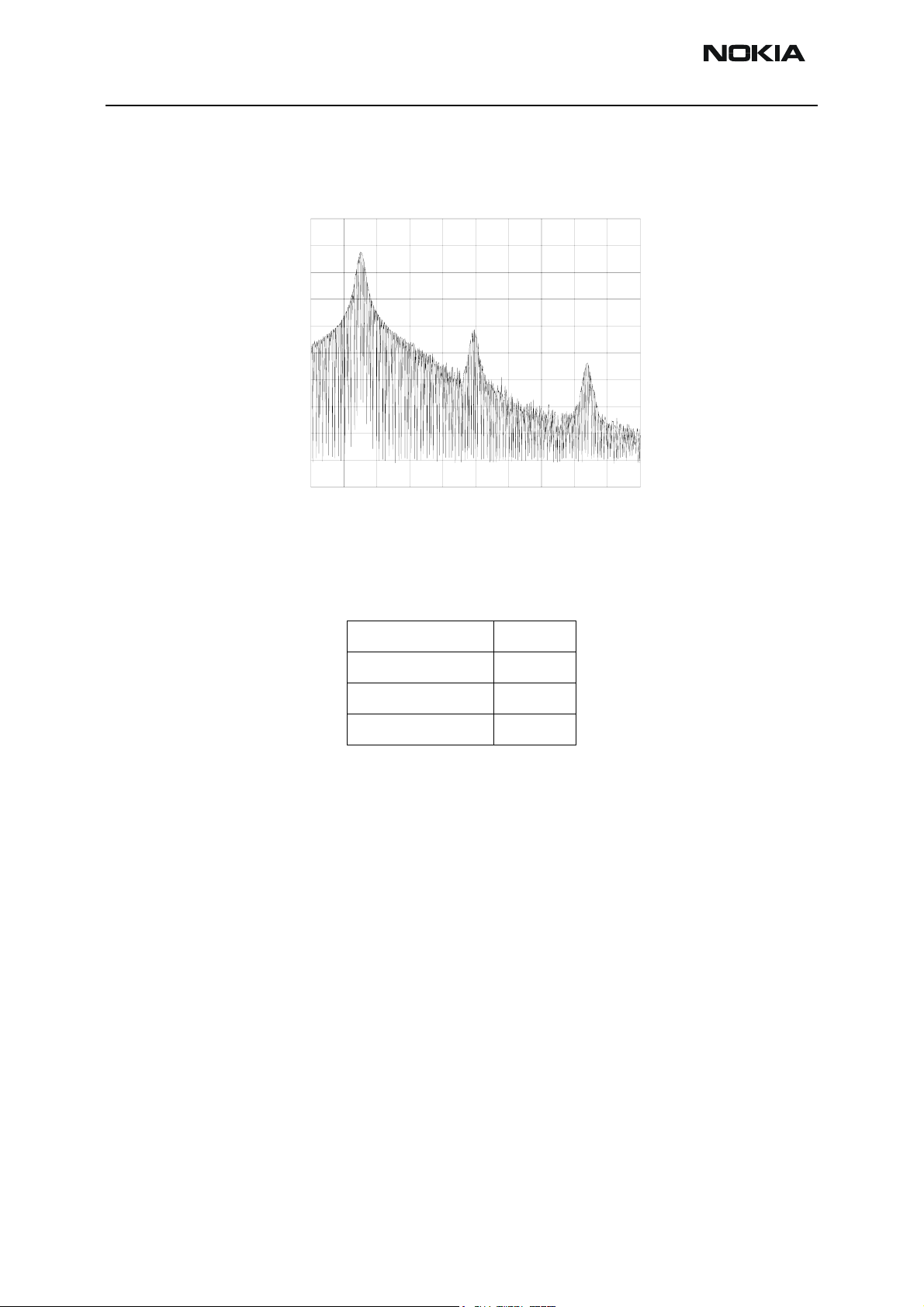
3 Set spectrum analyzer to required settings => OK.
4 To tune, set each of the sliders to a desired value.
Use <= , =>, PgUp or PgDn keys.
The sliders can be changed only when the tuning is ongoing.
The order of tuning should be same as the order of the sliders e.g. the Tx I DC offset is tuned first and phase difference is tuned last.
5 Tune LO leak to minimum with TXI/TXQ DC offset control (f0 on spectrum ana-
lyzer screen).
6 Tune wrong sideband to minimum using Amplitude/Phase difference controls
Issue 1 02/04 Copyright ©Nokia. All rights reserved. Page 65
Page 66
RH-26 Company Confidential
5 - Service Software Instructions CCS Technical Documentation
(f0+68kHz on spectrum analyzer screen).
GSMPOW Thu Aug 30 11: 43: 45 2001
REF 3 2 . 0 d Bm ATT 4 0 d B
10dB/
REF OFS
11. 5 dB
RBW
3kHz
VBW
3kHz
SWP
2. 0 s
CENTER 897. 4000 MHz SPAN 200. 0 kHz
A_wr i t eB_bl ank
Tx IQ Tuning limits are the same for all bands (GSM850, GSM1800 and
GSM1900):
I DC Offset -6…+6
7 Tuning automatically continues to the next step, EGSM 850 with EDGE on,
when you click “Save & Continue”.
EGSM850 band with EDGE On
1 To begin tuning, click “Start”.
2 Set spectrum analyzer to required settings for EGSM 850 band => OK.
3 Repeat the same tuning steps as for the EGSM850 with EDGE off above.
4 Tuning automatically moves to the next step, EGSM 1800 with EDGE off when
you click “Save & Continue”.
EGSM1800 band with EDGE Off
1 To begin tuning, click “Start”.
Q DC Offset -6…+6
Amplitude difference -1…+1
Phase difference 80°…100°
2 Set spectrum analyzer to required settings for GSM1800 band => OK.
3 Repeat the same tuning steps as for the EGSM850 band above.
Page 66 Copyright ©Nokia. All rights reserved. Issue 1 02/04
Page 67

Company Confidential RH-26
CCS Technical Documentation 5 - Service Software Instructions
4 Tuning automatically moves to the next step, EGSM 1800 with EDGE on, when
you press “Save & Continue”.
GSM1800 band with EDGE On
1 To begin tuning, click “Start”.
2 Set spectrum analyzer to required settings for GSM1800 band => OK.
3 Repeat the same tuning steps as for the EGSM850 band above.
4 Tuning automatically moves to the next step, EGSM 1900 with EDGE off, when
you click “Save & Continue”.
GSM1900 band with EDGE Off
1 To begin tuning, click “Start”.
2 Set spectrum analyzer to required settings for GSM 1900 band=> OK.
3 Repeat the same tuning steps as for the EGSM850 band above.
4 Tuning automatically moves to the next step, EGSM 1800 with EDGE on, when
you click “Save & Continue”.
GSM 1900 band with EDGE On
1 To begin tuning, click “Start”.
2 Set spectrum analyzer to required settings for GSM 1900 band=> OK.
3 Repeat the same tuning steps as for the EGSM850 band above.
4 To complete tuning, click “Save & Continue”.
5 To close the “Tx I/Q Tuning” dialog, click “OK”.
Issue 1 02/04 Copyright ©Nokia. All rights reserved. Page 67
Page 68

RH-26 Company Confidential
5 - Service Software Instructions CCS Technical Documentation
TX power level tuning
Power meter (or spectrum analyzer) is needed
With Tx Power Level Tuning, the coefficients are adjusted for each power level.
Tuning must be done separately on all bands!
When EDGE is on, tuning must be made for all power levels.
Tx power level tuning steps are:
• EGSM 850 PA High Mode with EDGE off
• EGSM 850 PA Low Mode with EDGE off (NOT IN USE FOR RH-26)
• EGSM 850 PA High Mode with EDGE on
• EGSM 850 PA Low Mode with EDGE on (NOT IN USE FOR RH-26)
• GSM1800 PA High Mode with EDGE off
• GSM1800 PA High Mode with EDGE on
• GSM1900 PA High Mode with EDGE off
• GSM1900 PA High Mode with EDGE on
Remember to take jig and cable attenuations into account!
To start power level tuning:
1 From the “Tuning” menu, choose“Tx Power Level Tuning”.
EGSM850 PA high mode with EDGE off
2 Click “Start”.
Page 68 Copyright ©Nokia. All rights reserved. Issue 1 02/04
Page 69

Company Confidential RH-26
CCS Technical Documentation 5 - Service Software Instructions
Tuning begins automatically from the EGSM850 band.
3 Set power meter (or spectrum analyzer) as required.
Note that TX PA mode is “High” at this point.
The coefficient table lists the power level, coefficient, target dBm and DAC value
for each power level.
4 To choose the tuned power level, use up and down arrows or mouse.
The current power level is shown with inverse colors.
5 Tune base level and power levels 19,15 and 5 to target level.
Issue 1 02/04 Copyright ©Nokia. All rights reserved. Page 69
Page 70

RH-26 Company Confidential
5 - Service Software Instructions CCS Technical Documentation
The tuning value can be adjusted with “-“ and “+” keys.
6 When tuning values are correct, click “Save & Continue”.
If all coefficients are within specified limits, tuning continues on the EGSM850
PA Low Mode with EDGE off.
EGSM850 PA low mode with EDGE off
This tuning step is not required for the RH-26 product, phone will not react to any controls.
7 Click “Save & Continue”.
If all coefficients are within specified limits, tuning will continue on the
EGSM850 PA High Mode with EDGE on.
EGSM 850 PA high mode with EDGE on
8 Set power meter (or spectrum analyzer) as required.
9 Repeat the same steps as for EGSM High and Low Mode above.
When EDGE is on, tuning must be made for all power levels.
10 Tune base level and all power levels from 19 to 8 to target level.
11 When tuning values are correct, click “Save & Continue”.
If all coefficients are within specified limits, tuning continues on the EGSM850
Page 70 Copyright ©Nokia. All rights reserved. Issue 1 02/04
Page 71
Company Confidential RH-26
CCS Technical Documentation 5 - Service Software Instructions
PA Low Mode with EDGE on.
EGSM850 PA low mode with EDGE on
This tuning step is not required for the RH-26 product, phone will not react to any controls.
12 Click “Save & Continue”.
If all coefficients are within specified limits, tuning continues on the GSM1800
PA High Mode with EDGE off
GSM1800 PA high mode with EDGE off
13 Set power meter (or spectrum analyzer) as required.
14 Repeat the same steps as for EGSM High and Low Mode above.
15 Tune base level and power levels 15,11 and 0 to target level.
16 When tuning values are correct, click “Save & Continue”.
If all coefficients are within specified limits, tuning continues on the GSM 1800
PA High Mode with EDGE on.
GSM1800 PA high mode with EDGE on
17 Set power meter (or spectrum analyzer) as required.
18 Repeat the same steps as for EGSM High and Low Mode above.
When EDGE is on, the tuning must be made for all power levels.
19 Tune base level
20 When tuning values are correct, click “Save & Continue”.
If all coefficients are within specified limits, tuning continues on the GSM 1900
PA High Mode with EDGE off.
GSM1900 PA high mode with EDGE off
21 Set power meter (or spectrum analyzer) as required.
and all power levels from 15 to 2 to target level.
22 Repeat the same steps as for EGSM High and Low Mode above.
23 Tune base level
24 When tuning values are correct, click “Save & Continue”.
If all coefficients are within specified limits, tuning continues on the GSM 1900
PA High Mode with EDGE on.
Issue 1 02/04 Copyright ©Nokia. All rights reserved. Page 71
and power levels 15,11 and 0 to target level.
Page 72

RH-26 Company Confidential
5 - Service Software Instructions CCS Technical Documentation
GSM1900 PA high mode with EDGE on
25 Set Power Meter (or Spectrum analyzer) as required.
26 Repeat the same steps as for EGSM High and Low Mode above.
When EDGE is on, the tuning must be made for all power levels.
27 Tune base level and all power levels from 15 to 2 to target level.
28 When tuning values are correct, click “Save & Continue”.
The values are saved to phone’s memory.
29 To end tuning, close the “TX Power Level Tuning” dialog.
Typical values: EGSM850
Power
level
5 0.700…0.850 -
7 - 0.500…0.600
15 0.210…0.230 0.210…0.230
19 0.180…0.200 0.180…0.200
Base 0.150…0.170 0.150…0.170
Typical values: GSM1800
PA high mode PA low mode
Power level PA high mode
0 0.700…0.800
11 0.180…0.230
15 0.150…0.200
Base 0.150…0.170
Typical values: GSM1900
Power level PA high mode
0 0.800…0.900
11 0.180…0.230
15 0.150…0.200
Base 0.150…0.170
Page 72 Copyright ©Nokia. All rights reserved. Issue 1 02/04
Page 73

Company Confidential RH-26
CCS Technical Documentation 5 - Service Software Instructions
Flashing Setup Instructions
Flash concept with FPS-8
Item Type Description Code
1 SF-5 Point of sales flash loading adapter 0770652
2 FLC-2 Power cable 0730185
3 XCS-4 Modular cable 0730178
4 FPS-8 Flash prommer box 0080321
5 Centronics (printer) cable, incl. in FPS-8 sales package 0730029
6 AXS-4 RS-232 (D9-D9) cable, incl. in FPS-8 sales package 0730090
7 PKD-1 Software protection key (Dongle) 0750018
8 Service SW ???????
9 ACF-8 AC charger, incl. in FPS-8 sales package 0680032
Issue 1 02/04 Copyright ©Nokia. All rights reserved. Page 73
Page 74

RH-26 Company Confidential
5 - Service Software Instructions CCS Technical Documentation
POS (Point of Sales) flash concept
Item Type Description Code
1 SF-5 Point of sales flash loading adapter 0770652
2 XCS-1 Service cable 0730218
3 ACP-8 AC charger 0675***
4 FLS-4S POS flash dongle, for EMEA area 0080541
4 FLS-4S POS flash dongle, for APAC area 0080542
5 SW
Page 74 Copyright ©Nokia. All rights reserved. Issue 1 02/04
Page 75

Company Confidential RH-26
CCS Technical Documentation 5 - Service Software Instructions
JBV-1 flash concept
Item Type Description Code
1 JBV-1 Docking station 0770298
2 DA-6 Docking station adapter 0770653
3 PCS-1 DC power cable 0730012
4 XCS-4 Modular cable 0730178
5 FPS-8 Flash prommer box 0080321
6 Centronics (printer) cable, incl. in FPS-8 sales
package
7 AXS-4 RS232 (D9-D9) cable, incl. in FPS-8 sales
package
8 PKD-1 Software protection key (Dongle) 075 0018
9 SW
10 ACF-8 AC charger, incl. in FPS-8 sales package 0680032
0730029
0730090
Issue 1 02/04 Copyright ©Nokia. All rights reserved. Page 75
Page 76

RH-26 Company Confidential
5 - Service Software Instructions CCS Technical Documentation
JBV-1 baseband tuning concept
Item Service accessory Type Product code
1 JBV-1 Docking station 0770298
2 DA-6 Docking station adapter 0770653
3 SCB-3 DC-DC cable 0730114
4 XRF-1 Antenna cable 0730085
5 PCS-1 DC power cable 0730012
6 DAU-9S Service MBUS cable 0730108
7 PKD-1 Software protection key (Dongle) 0750018
8 SW
Page 76 Copyright ©Nokia. All rights reserved. Issue 1 02/04
Page 77

Company Confidential RH-26
CCS Technical Documentation 5 - Service Software Instructions
Parallel flash concept
Item Type Description Code
1 JBV-1 Docking station 0770298
2 DA-6 Docking station adapter 0770653
3 XCS-4 Modular cable 0730178
4 PCS-1 DC power cable 0730012
5 FPS-8C Parallel flash prommer 0080396
6 AXS-4 RS232 (D9-D9) cable, incl. in FPS-8C sales
package
7 Printer Cable Centronics (printer) cable, incl. in FPS-8C
sales package
8 PKD-1 Software protection key (Dongle) 0750018
9 SW
0730090
0730029
Issue 1 02/04 Copyright ©Nokia. All rights reserved. Page 77
Page 78

RH-26 Company Confidential
5 - Service Software Instructions CCS Technical Documentation
[This page intentionally blank]
Page 78 Copyright ©Nokia. All rights reserved. Issue 1 02/04
 Loading...