

Page 1
nokia
CONNECTING PEOPLE
PAGE 1 (23) Approved 1.0
Nokia Mobile Phones Customer Care EMEA
Technical Services, Repair Concepts Confidential 20.03.2003
SQX 00618-en DJk
nokia
6800
NHL-6
SERVICE MANUAL
Service Level 1&2
Copyright © Nokia Corporation. This material, including documentation and any related computer programs,
is protected by copyright controlled by Nokia Mobile Phones. All rights are reserved. Copying, including
reproducing, storing, adapting or translating, any or all of this material requires the prior written consent
of Nokia Mobile Phones. This material also contains confidential information, which may not be disclosed
to others without the prior written consent of Nokia Mobile Phones.
Service Manual 6800 Level 1&2 Copyright 2003 © Nokia Corporation
Page 2

nokia
CONNECTING PEOPLE
PAGE 2 (23) Approved 1.0
Nokia Mobile Phones Customer Care EMEA
Technical Services, Repair Concepts Confidential 20.03.2003
SQX 00618-en DJk
Introduction
The purpose of this document is to help Nokia service levels 1 and 2 workshop
technicians to carry out service to Nokia 6800. This Service Manual is to be used only by
authorized Nokia service partners, and the content of it is confidential. Please note that
Nokia provides also other guidance documents (e.g. Service Bulletins) for service
partners, follow these regularly and comply with the given instructions.
While every endeavor has been made to ensure the accuracy of this document, some
errors may exist. If you find any errors or if you have further suggestions, Nokia should
be notified. Please keep in mind also that this documentation is continuously being
updated and modified, so watch always out for the newest version.
Warnings and Cautions
Please refer to the phone’s user guide for instructions relating to operation, care and maintenance
including important safety information. Note also the following:
Warnings:
1.
CARE MUST BE TAKEN ON INSTALLATION IN VEHICLES FITTED WITH ELECTRONIC ENGINE
MANAGEMENT SYSTEMS AND ANTI–SKID BRAKING SYSTEMS. UNDER CERTAIN FAULT
CONDITIONS, EMITTED RF ENERGY CAN AFFECT THEIR OPERATION. IF NECESSARY, CONSULT THE
VEHICLE DEALER/MANUFACTURER TO DETERMINE THE IMMUNITY OF VEHICLE ELECTRONIC
SYSTEMS TO RF ENERGY.
2.
THE HANDPORTABLE TELEPHONE MUST NOT BE OPERATED IN AREAS LIKELY TO CONTAIN
POTENTIALLY EXPLOSIVE ATMOSPHERES EG PETROL STATIONS (SERVICE STATIONS), BLASTING
AREAS ETC.
3.
OPERATION OF ANY RADIO TRANSMITTING EQUIPMENT, INCLUDING CELLULAR TELEPHONES, MAY
INTERFERE WITH THE FUNCTIONALITY OF INADEQUATELY PROTECTED MEDICAL DEVICES. CONSULT
A PHYSICIAN OR THE MANUFACTURER OF THE MEDICAL DEVICE IF YOU HAVE ANY QUESTIONS.
OTHER ELECTRONIC EQUIPMENT MAY ALSO BE SUBJECT TO INTERFERENCE.
Cautions:
1. Servicing and alignment must be undertaken by qualified personnel only.
2. Ensure all work is carried out at an anti–static workstation and that an anti–static wrist strap is
worn.
3. Ensure solder, wire, or foreign matter does not enter the telephone as damage may result.
4. Use only approved components as specified in the parts list.
5. Ensure all components, modules screws and insulators are correctly re–fitted after servicing and
alignment. Ensure all cables and wires are repositioned correctly.
6. All PC’s used with NMP Service Software for this produce must be bios and operating system ”Year
2000 Compliant”.
Service Manual 6800 Level 1&2 Copyright 2003 © Nokia Corporation
Page 3
nokia
CONNECTING PEOPLE
PAGE 3 (23) Approved 1.0
Nokia Mobile Phones Customer Care EMEA
Technical Services, Repair Concepts Confidential 20.03.2003
SQX 00618-en DJk
Table of content
1. EXPLODED VIEW AND COMPONENT DISPOSAL.......................................................................... 4
2. SPARE PARTS LIST................................................................................................................................. 5
3. INFRARED GONOGO TEST .................................................................................................................. 9
4. SW-UPDATE ............................................................................................................................................ 10
4. GENERAL REPAIR INFORMATION ................................................................................................. 11
5. DISASSEMBLY INSTRUCTIONS (ALSO SEE VIDEOS ON CARE POINT) ................................ 12
6. EXCHANGE OF DOME SHEET (LEVEL 2 ONLY) .......................................................................... 16
7. QUICK TROUBLE SHOOTER PART1 ............................................................................................... 18
8. QUICK TROUBLE SHOOTER PART2 ............................................................................................... 19
9. QUICK TROUBLE SHOOTER PART3 ............................................................................................... 20
10. ESD PROTECTION REQUIREMENTS........................................................................................... 21
11. SERVICE NOTES................................................................................................................................ 22
12. GONOGO TESTER............................................................................................................................. 23
13. BATTERY TESTER ............................................................................................................................ 23
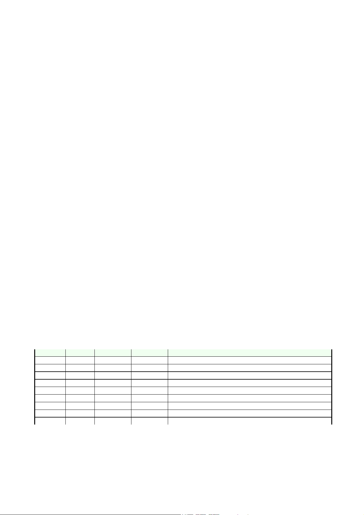
Change History
Originator Status Version No. Date Comments
DJk Draft 0.1 05.02.2003 Initial draft
DJk Draft 0.2 20.03.2003 Component Disposal incl., General Repair Information modified
DJk Approved 1.0 20.03.2003 Approval
Service Manual 6800 Level 1&2 Copyright 2003 © Nokia Corporation
Page 4

nokia
CONNECTING PEOPLE
PAGE 4 (23) Approved 1.0
Nokia Mobile Phones Customer Care EMEA
Technical Services, Repair Concepts Confidential 20.03.2003
SQX 00618-en DJk
1. EXPLODED VIEW AND COMPONENT DISPOSAL
Recommendation for the ecologically friendly disposal of components. Colorized components show the different categories.
Description: See corresponding ITEM/CIRCUIT REF of the SPL (Spare Parts List)
Service Manual 6800 Level 1&2 Copyright 2003 © Nokia Corporation
Page 5
nokia
CONNECTING PEOPLE
PAGE 5 (23) Approved 1.0
Nokia Mobile Phones Customer Care EMEA
SQX 00618-en DJk
Technical Services, Repair Concepts Confidential 20.03.2003
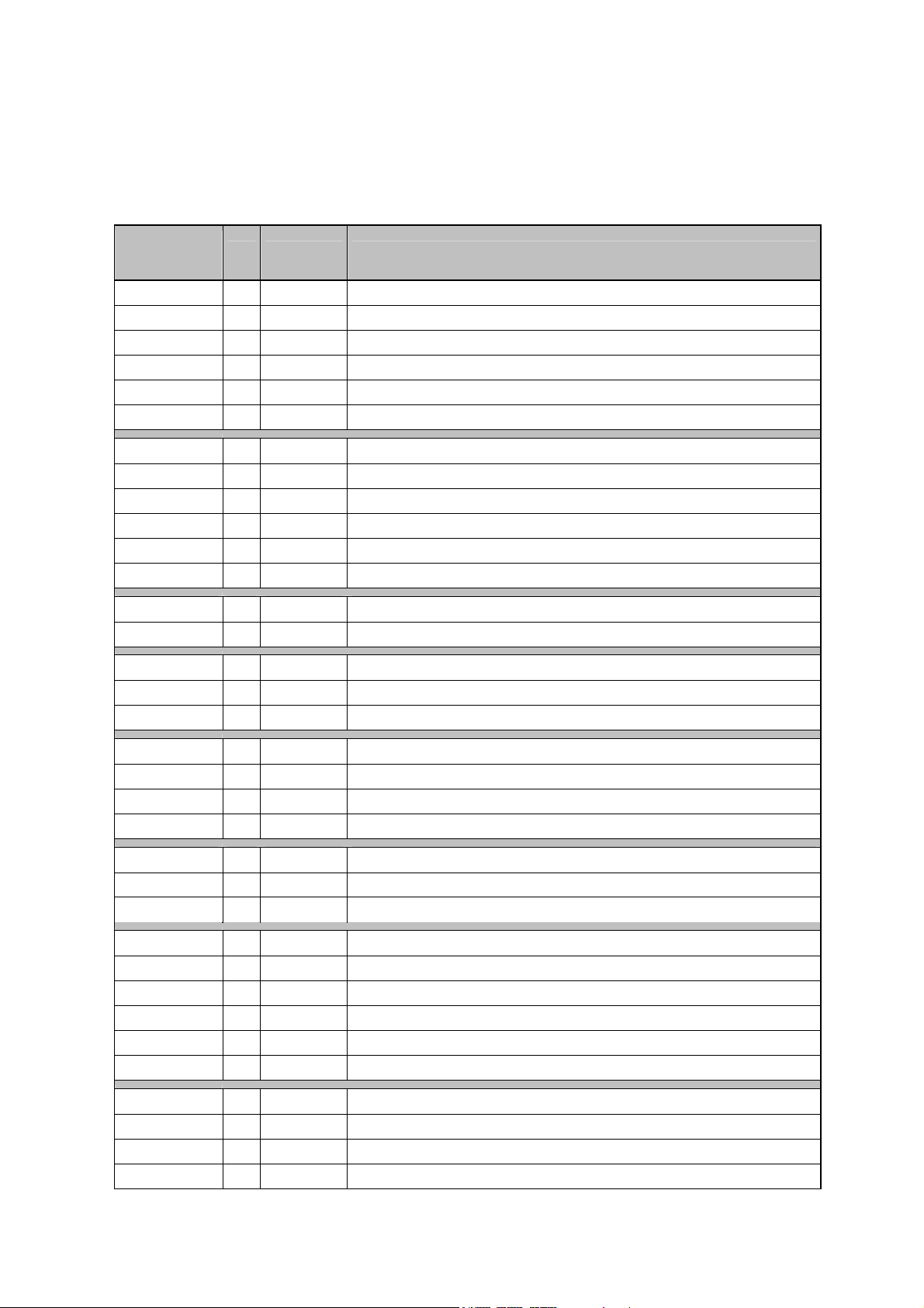
2. SPARE PARTS LIST
ITEM/
CIRCUIT REF.
I001 1 - FLIP T9 KEYMAT
I002 1 - FLIP COVER
I003 1 - FLIP KEYMAT LEFT COMMON
I004 2 - FLIP HINGE
I005 2 - FLIP CONTACT PINS
I006 1 - A-COVER
I007 2 - A-COVER TOP CONTACT PADS
I008 2 - A-COVER BOTTOM CONTACT PADS
I009 1 9790558 FUNCTION KEYS
I010 1 - MENU KEY
I011 1 9790747 KEYMAT RIGHT COMMON
I012 5 6150051 SCREW M1.6x5.5 T6+
I013 1 - LCD METAL FRAME
I014 1 - EARPIECE
I015 1 4850265 LCD MODULE 128X128 COF COLOURSTN
I016 1 9460432 LIGHTGUIDE NHL-6
I017 1 9795104
I018 1 - TB9 RADIOMODULE
I019 1 - ANTENNA
I020 1 - INTERNAL HANDSFREE SPEAKER
I021 1 9452186 VOLUME KEY
I022 1 5400243 DC-JACK 3.5MM
I023 1 5140265 MICROPHONE + HOLDER
I024 1 6800063 VIBRA MOTOR + RUBBER
I025 1 9460468 VIBRA HOLDER
I026 1 9430419 LOGO BRACKET DMD08256 NHL-6
I027 1 - B-COVER
I028 1 - METAL SHIELD
I029 1 - BATTERY RELEASE BUTTON
QTY PART NO PART NAME
1 0262868 FLIP MOD COMMON (I001-I005)
1 9490456 A-COVER ASSY (I006-I010)
1 9467074 LCD METAL FRAME MODULE (I013-I014)
DOME SHEET MAINPWB (Level 2 only)
1 0660274 ANTENNA WITH IHF (I019-I020)
1 - B-COVER ASSY (I027-I029)
Service Manual 6800 Level 1&2 Copyright 2003 © Nokia Corporation
Page 6
nokia
CONNECTING PEOPLE
PAGE 6 (23) Approved 1.0
Nokia Mobile Phones Customer Care EMEA
SQX 00618-en DJk
Technical Services, Repair Concepts Confidential 20.03.2003
ITEM/
CIRCUIT REF.
I030 2 6150077 SCREW M1.6x6.2
I031 1 - TYPE LABEL ROLL
I032 1 9452172 BATTERY COVER
QTY PART NO PART NAME
SOLDERING COMPONENTS ONLY FOR LEVEL 2
ITEM/
CIRCUIT REF.
F100 1 5119019
G300 1 4700133
S334 1 5200025
S335 1 5200025
V311 1 4864537
V312 1 4864537
V313 1 4864537
V315 1 4860333
V316 1 4860333
V317 1 4860333
QTY PART NO PART NAME
SM FUSE F 1.5A 32V 0603
CELL CAPACITOR 0.01MAH 3V3
SM TACT SW SIDE TRAVEL 0.2 MM
SM TACT SW SIDE TRAVEL 0.2 MM
LED CL270WBHE** RESERVED HDB18 **
LED CL270WBHE** RESERVED HDB18 **
LED CL270WBHE** RESERVED HDB18 **
LED LWL88S *** RESERVEDHDB18 ***
LED LWL88S *** RESERVEDHDB18 ***
LED LWL88S *** RESERVEDHDB18 ***
Service Manual 6800 Level 1&2 Copyright 2003 © Nokia Corporation
Page 7
nokia
CONNECTING PEOPLE
PAGE 7 (23) Approved 1.0
Nokia Mobile Phones Customer Care EMEA
SQX 00618-en DJk
Technical Services, Repair Concepts Confidential 20.03.2003
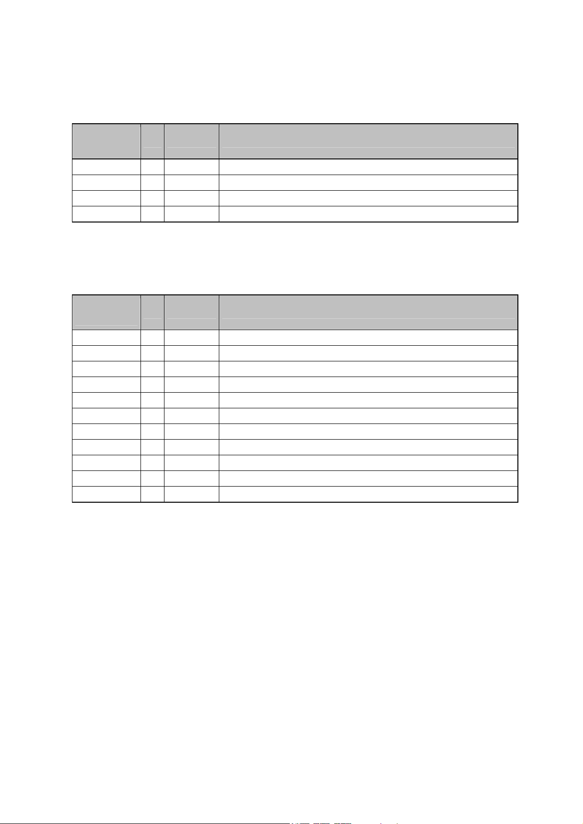
VARIANT PARTS
ITEM/
CIRCUIT REF.
0262868
0201937
0262869
0262870
0262871
0262872
0262873
0262877
0262874
0262875
I011
I011
I011
I011
I011
I011
I011
I011
I011
I011
I011
I011
I011
I011
QTY PART NO PART NAME
Flip mod Common Eng / Latin (Common English)
Flip mod Skandi / Latin (Scandinavian)
Flip mod DE-EE / Latin (German /Estonian)
Flip mod FR /Latin (French)
Flip mod IT-SP-PT (Italian /Spanish /Portuguese)
Flip mod TR / Latin (Turkey)
Flip mod CZ-SV-RO / Latin (Czech/Slovak/Romanian)
Flip mod GR / Greek
Flip mod HU / Latin (Hungarian)
Flip mod PL / Latin (Polish)
0262879 Flip mod RU-UA-LV-SR /Latin (Russia/Ukraina/Latvian/Lithuanian)
0262876 Flip mod CR-SL-SR / Latin (Croatian/Slovenian/Serbia)
0262878 Flip mod Hebrew / Hebrew
0262889 Flip mod Arabic / Arabic
9790747 Keymat right Common Eng DMC05411
9790748 Keymat right Skandi DMC04587
9790773 Keymat right DE-EE DMC05532
9790767 Keymat right FR DMC05549
9790771 Keymat right IT-SP-PT DMC05536
9790772 Keymat right TR DMC05534
9790765 Keymat right CZ-SV-RO DMC05553
9790764 Keymat right GR DMC05555
9790770 Keymat right HU DMC05538
9790768 Keymat right PL DMC05540
9790789 Keymat right RU-UA-LV-SR DMC05644
9790766 Keymat right CR-SL-SR DMC05551
9790763 Keymat right Hebrew DMC05557
9790811 Keymat right Arabic DMC05782
Service Manual 6800 Level 1&2 Copyright 2003 © Nokia Corporation
Page 8

nokia
CONNECTING PEOPLE
PAGE 8 (23) Approved 1.0
Nokia Mobile Phones Customer Care EMEA
SQX 00618-en DJk
Technical Services, Repair Concepts Confidential 20.03.2003
SWAP UNITS
QTY PART NO PART NAME
0076207 N6800 NHL-6 SWAP ENGINE UK/BENEL
0076216 N6800 NHL-6 SWAP ENGINE DE/EST
0076217 N6800 NHL-6 SWAP ENGINE SCANDI
0076218 N6800 NHL-6 SWAP ENGINE FR
0076219 N6800 NHL-6 SWAP ENGINE IT/ES/PT
0076220 N6800 NHL-6 SWAP ENGINE TURKEY
0076221 N6800 NHL-6 SWAP ENGINE CS/SK/RO
0076222 N6800 NHL-6 SWAP ENGINE GREECE
0076223 N6800 NHL-6 SWAP ENGINE HUNGARY
0076224 N6800 NHL-6 SWAP ENGINE POLAND
0076225 N6800 NHL-6 SWAP ENGINE RU/LT/LV
0076226 N6800 NHL-6 SWAP ENGINE HR/SL/SR
0076227 N6800 NHL-6 SWAP ENGINE ARABIC
0076230 N6800 NHL-6 SWAP ENGINE SOUTH AFR
SERVICE TOOLS
TYPE QTY PART NO PART NAME
ACCESSORY
ACCESSORY
ACCESSORY
ACCESSORY
Level 2 only
Level 2 only
0080541 FLS-4S SALES PACK E&A (inclusive 0680032)
0680032 UNIV. POWERSUPPLY ACF-8
0271738 BLC-2 BATT.BLOCK LI-ION 950MAH
0273505 HDS-3 STEREO HEADSET
0272169 AC TRAVEL CHARGER ACP-8E (EURO)
0272172 AC TRAVEL CHARGER ACP-8X (UK)
0730218 XCS-1 SERVICE CABLE
0775306 FLA-29 POS Flash Adapter
0770616 SS-4 DOMESHEET ASSEMBLY JIG
0770408 MJS-70 SOLDERING JIG
0770431 SRT-6 Opening Tool
0770450 FLA-30 TESTPINS (10 PCS)
Service Manual 6800 Level 1&2 Copyright 2003 © Nokia Corporation
Page 9
nokia
CONNECTING PEOPLE
PAGE 9 (23) Approved 1.0
Nokia Mobile Phones Customer Care EMEA
Technical Services, Repair Concepts Confidential 20.03.2003
SQX 00618-en DJk
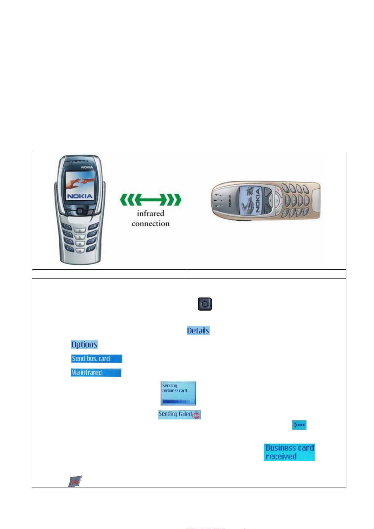
3. INFRARED GONOGO TEST
You need another infrared device (e.g. 6310i) to do a GoNoGo test. The infrared windows
of the devices must be directed to each other and should have a distance of approximate
15 cm. Make sure that infrared is activated in receiver device.
Warning: Do not point the IR (infrared) beam at anyone’s eye or allow it to interfere
with other IR devices. This device is a Class 1 Laser product.
Test unit Reference unit
Settings on the test unit:
o From Home Menu, push the navigation key
up or down. This displays Phonebook
entries. If phone and SIM memory is empty, create one new entry.
o Choose one phonebook entry and select
o
Select
o
Select
o Select
Sending in progress, please wait
o
.
o If sending of business card fails
, make sure again, that infrared windows
are directed to each other and infrared is activated in reference device
again sending.
Then try
.
o Test was successful, if you get this message on receiver device
.
You will not get a confirmation on sender device.
o Press
Service Manual 6800 Level 1&2 Copyright 2003 © Nokia Corporation
for Home Menu.
Page 10
nokia
CONNECTING PEOPLE
PAGE 10 (23) Approved 1.0
Nokia Mobile Phones Customer Care EMEA
Technical Services, Repair Concepts Confidential 20.03.2003
SQX 00618-en DJk
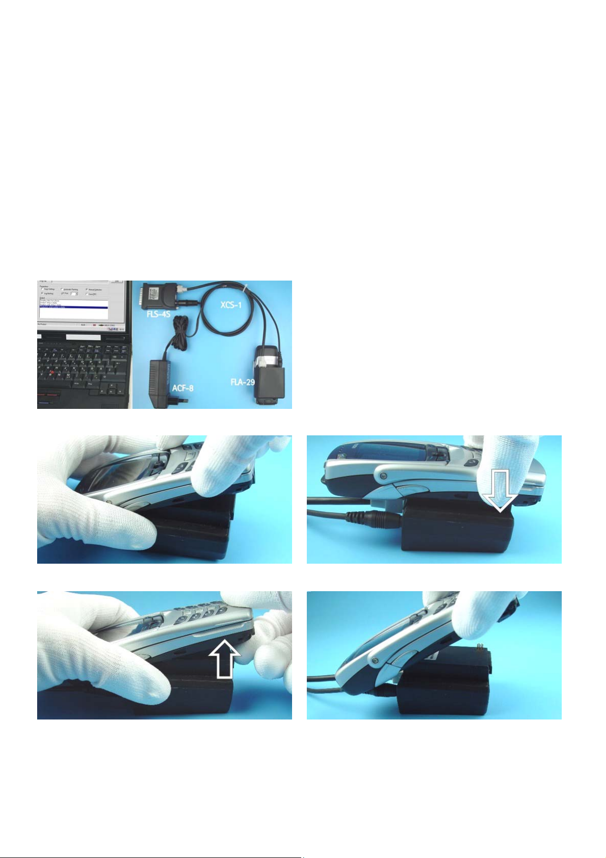
4. SW-UPDATE
To use FLS-4S Flash Dongle you have to follow the user guide inside the sales package.
Please check always for the latest version of flash software, which is available on
Nokia Partner Web Site.
Flash Concept – (Point of Sales)
It is very important to follow this insertion and
removal procedure, otherwise the contact pins of
Flash Adapter will be damaged.
Insert the Flash Adapter FLA-29 like a battery, start at the
Battery Connector side.
Now, push down the bottom side of the phone, do not
use too much force.
When removing the Flash Adapter, always start from the
bottom side of the unit.
Service Manual 6800 Level 1&2 Copyright 2003 © Nokia Corporation
Take away the unit now.
Page 11

nokia
CONNECTING PEOPLE
PAGE 11 (23) Approved 1.0
Nokia Mobile Phones Customer Care EMEA
Technical Services, Repair Concepts Confidential 20.03.2003
SQX 00618-en DJk
4. GENERAL REPAIR INFORMATION
In this section the technician will get some general hints how to carry out repairs:
o Before starting the repair you must take care of ESD precautions like being in your ESD Protected
Area and connecting your wristband.
o Use gloves to avoid corrosion and fingerprints.
o Protect windows and displays with a foil to avoid dust and scratches.
o When cleaning the pads you have to use a soft cloth/ESD brush and Isopropanol. It is not allowed to
use a glass fiber pencil because it scratches the surface and will lead later on to corrosion.
o
Mechanical parts (except shielding lids), which didn’t repair the failure, can be reused, if they are
not soldered.
o When removing the shielding lids make sure to replace them with new ones, otherwise the high-
frequency leakage can have an influence on the device.
o Use always original Nokia spare parts.
o Remove redundant soldering flux after repair.
o Meet the torque requirements when assembling the unit (see also the document “torques for
transceiver assembly” on Nokia Partner Web Site).
o Always use your own equipment for testing where you are sure that it works. E.g. if the customer
complains about charger function, please test the phone with your own charger to be sure if phone
or charger causes the malfunction.
o When doing the Faultlogger entries, always note the Item code, which caused the malfunction. Also,
fill in the appropriate part code from the assembly, if needed.
o Please be aware that some malfunctions could be software related and solved by an update.
Following General Service Bulletins have to be followed:
SB-027: Original Nokia Accessories
SB-055: Common notice for good ventilation
SB-089: Don’t try to repair prototypes (indicated on Type Label).
SB-107: Be sure that you have minimum hardware requirements in place.
SB-115: Handling of liquid damages.
SB-121: Return the defective part, if one of your service tools causes malfunction.
SB-122: Soldering with manual hot air gun is totally forbidden because of the very sensitive
SB-124 Service Policy for packaging serviced products
SB-131: Check these guidelines when refurbishing products.
SB-148: Improvements To Faultlog Reporting Tool
SB-156: Packing Material
Please check Nokia Partner Web Site (PWS) for latest news and files on a regular basis.
µBGA components and µVia technology.
Service Manual 6800 Level 1&2 Copyright 2003 © Nokia Corporation
Page 12

nokia
CONNECTING PEOPLE
PAGE 12 (23) Approved 1.0
Nokia Mobile Phones Customer Care EMEA
Technical Services, Repair Concepts Confidential 20.03.2003
SQX 00618-en DJk
5. DISASSEMBLY INSTRUCTIONS (ALSO SEE VIDEOS ON CARE POINT)
Protect LCD window to avoid dust and scratches.
Press Release Button before removing Battery Cover.
Unscrew the two TORX PLUS® size 6 screws, using the
order shown. For assembly, the reverse order and a
torque of 17Ncm have to be used. Use always new
screws.
Now, the same procedure on the other side.
Place the SRT-6 between B-Cover and A-Cover, and shift
it carefully as shown in the picture. Note the correct
position of the SRT-6, tip should not touch the PWB.
Separate the engine from A-Cover.
Protect LCD to avoid dust and scratches.
Keymat drops out when turning A-Cover.
Service Manual 6800 Level 1&2 Copyright 2003 © Nokia Corporation
Page 13

nokia
CONNECTING PEOPLE
PAGE 13 (23) Approved 1.0
Nokia Mobile Phones Customer Care EMEA
Technical Services, Repair Concepts Confidential 20.03.2003
Open the Flip Cover.
Separate A-Cover from Flip Cover as shown in the picture.
Note, the right position of the Flip Hinges on reassembly.
SQX 00618-en DJk
Function Keys are attached with four snaps to A-cover.
Use SRT-6 to release the snaps. Take care not to damage
the spring contacts.
Unscrew the five TORX PLUS® size 6 screws, using the
order shown. For assembly, the reverse order and a
torque of 17Ncm have to be used. Use always new
screws.
Remove Function Keys. Use always new keys in
reassembly!
Lift the engine from B-Cover.
Open the Light Guide snaps.
Remove the Light Guide.
Service Manual 6800 Level 1&2 Copyright 2003 © Nokia Corporation
Page 14

nokia
CONNECTING PEOPLE
PAGE 14 (23) Approved 1.0
Nokia Mobile Phones Customer Care EMEA
Technical Services, Repair Concepts Confidential 20.03.2003
The LCD Metal Frame is attached with snaps to the Radio
Module on both sides. SRT-6 can be used to release the
snaps.
Release the snap on the other side of the engine and take
away the LCD Module.
SQX 00618-en DJk
Note the right position of the LCD Module in LCD Metal
Frame when assembling. Also take care not to damage
the LCD spring contacts on Radio Module.
Do not remove the Earpiece from the LCD Frame, as they
are supplied as one part.
Separate the LCD Metal Frame from LCD Module and
protect the LCD window again.
Volume Key can be removed easily.
To remove the DC Jack, place tweezers between the
spring contacts and under the Jack. You’ll need to use
additional force to pull the Jack upwards.
Use tweezers to pull up the Microphone.
Service Manual 6800 Level 1&2 Copyright 2003 © Nokia Corporation
Page 15

nokia
CONNECTING PEOPLE
PAGE 15 (23) Approved 1.0
Nokia Mobile Phones Customer Care EMEA
Technical Services, Repair Concepts Confidential 20.03.2003
Remove the Vibra Motor from its guidance.
Place the SRT-6 between the spring contacts and lift up
the Antenna carefully. Do not damage the spring contacts
and the Antenna Radiator, when removing the Antenna.
SQX 00618-en DJk
Remove the Antenna from B-Cover.
After releasing of the snaps, the Logo Bracket can be
removed.
The Logo Bracket is attached with snaps to the B-Cover.
Take care not to break the snaps when releasing the
Bracket.
Service Manual 6800 Level 1&2 Copyright 2003 © Nokia Corporation
Page 16

nokia
CONNECTING PEOPLE
PAGE 16 (23) Approved 1.0
Nokia Mobile Phones Customer Care EMEA
Technical Services, Repair Concepts Confidential 20.03.2003
SQX 00618-en DJk
6. EXCHANGE OF DOME SHEET (LEVEL 2 ONLY)
It is very important to check the conditions of the Dome Sheet and the Radio
Module. If small amount of any liquid is recognized, it is recommended
to clean the PWB and to change the Dome Sheet.
Please note: Any liquid damage is a non-warranty repair!
Remove the defective Dome Sheet carefully.
Place the Radio Module on the Jig. Note the guiding pins.
Put the new Dome Sheet onto the Dome Sheet Assembly
Jig. Note the guiding pins. Remove the protection foil.
Press on the Radio Module evenly.
Lift the Radio Module with the new Dome Sheet from the
Jig.
Check that the Dome Sheet is correctly stuck to the Radio
Module. Do not damage the spring contacts of LCD
connector.
Service Manual 6800 Level 1&2 Copyright 2003 © Nokia Corporation
Page 17

nokia
CONNECTING PEOPLE
PAGE 17 (23) Approved 1.0
Nokia Mobile Phones Customer Care EMEA
Technical Services, Repair Concepts Confidential 20.03.2003
SQX 00618-en DJk
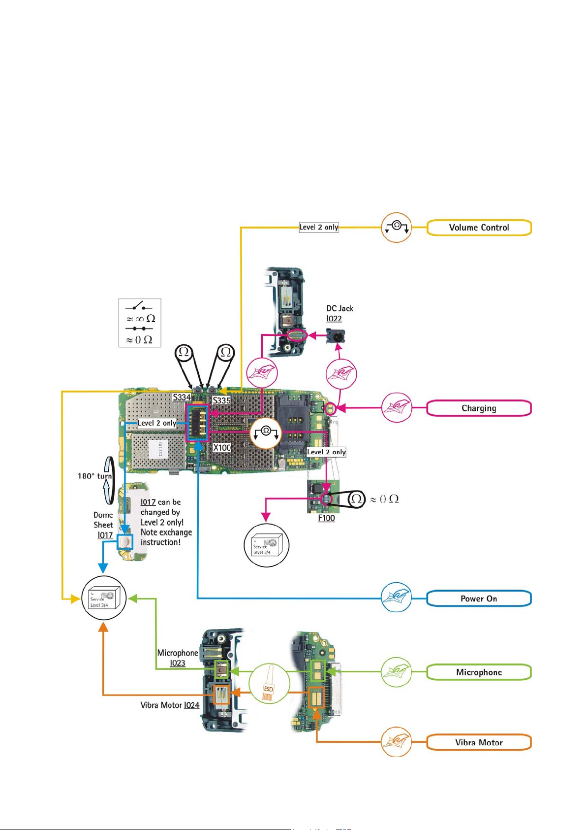
This legend is valid for all parts of the Quick Trouble Shooter
Follow the steps until the problem is solved. If this doesn’t help, you are not authorized to go
forward. Only underlined components ( e.g. I023
Follow the arrows step by step
Pads or contacts: Check optical and mechanical condition particularly regarding to
corrosion. Clean if necessary.
Measure component for electrical functionality and change, if needed.
No more actions possible, send product to the appropriate service partner with higher
service level.
) can be changed.
Pads or contacts: Check optical and mechanical condition particularly regarding to
corrosion. Clean with ESD brush only, if necessary.
Service Manual 6800 Level 1&2 Copyright 2003 © Nokia Corporation
Page 18

nokia
CONNECTING PEOPLE
PAGE 18 (23) Approved 1.0
Nokia Mobile Phones Customer Care EMEA
Technical Services, Repair Concepts Confidential 20.03.2003
SQX 00618-en DJk
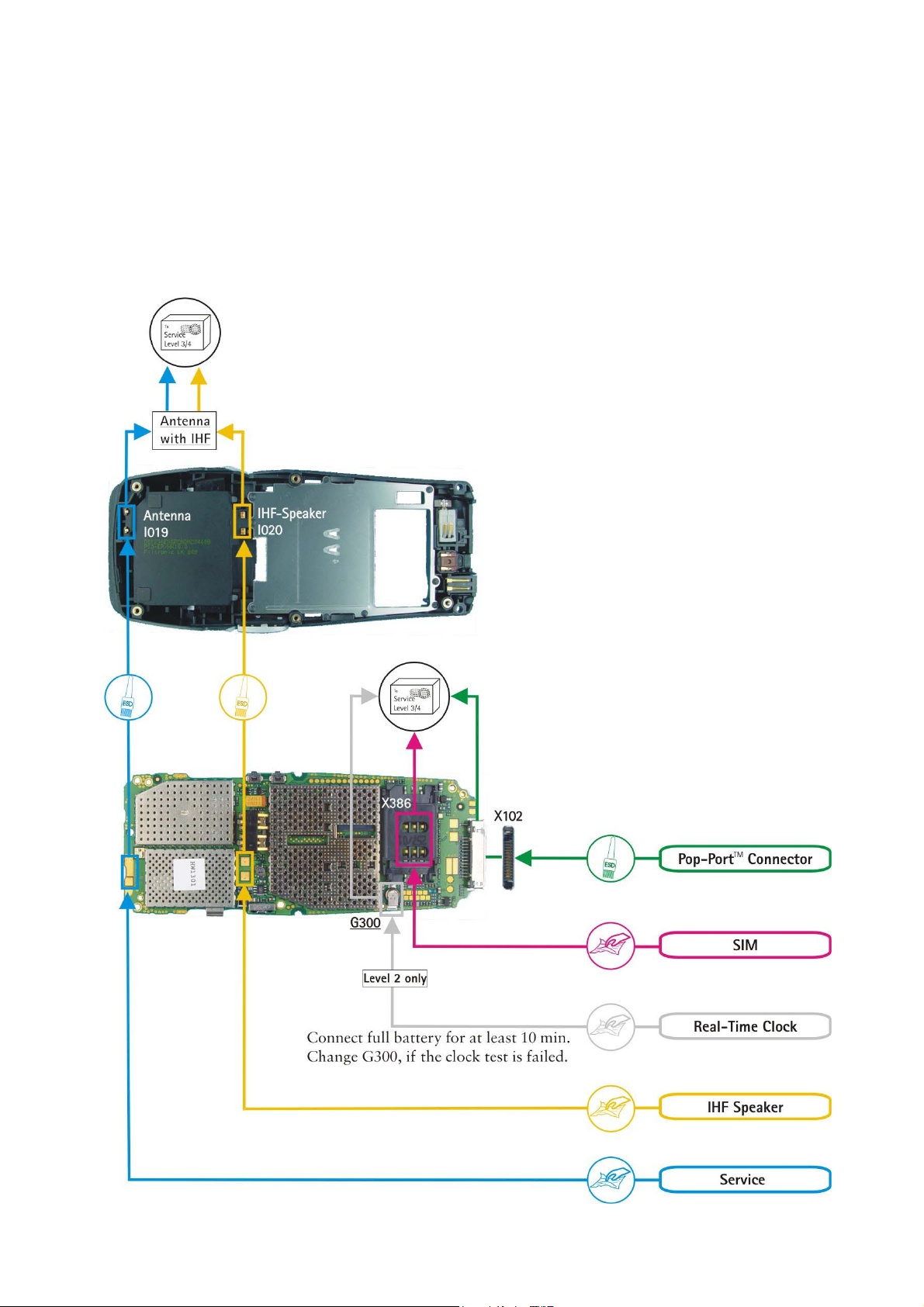
7. QUICK TROUBLE SHOOTER PART1
Service Manual 6800 Level 1&2 Copyright 2003 © Nokia Corporation
Page 19
nokia
CONNECTING PEOPLE
PAGE 19 (23) Approved 1.0
Nokia Mobile Phones Customer Care EMEA
Technical Services, Repair Concepts Confidential 20.03.2003
SQX 00618-en DJk
8. QUICK TROUBLE SHOOTER PART2
Service Manual 6800 Level 1&2 Copyright 2003 © Nokia Corporation
Page 20
nokia
CONNECTING PEOPLE
PAGE 20 (23) Approved 1.0
Nokia Mobile Phones Customer Care EMEA
Technical Services, Repair Concepts Confidential 20.03.2003
SQX 00618-en DJk
9. QUICK TROUBLE SHOOTER PART3
Service Manual 6800 Level 1&2 Copyright 2003 © Nokia Corporation
Page 21

nokia
CONNECTING PEOPLE
PAGE 21 (23) Approved 1.0
Nokia Mobile Phones Customer Care EMEA
Technical Services, Repair Concepts Confidential 20.03.2003
SQX 00618-en DJk
10. ESD PROTECTION REQUIREMENTS
Electrostatic discharge can easily damage the sensitive components of
electronic products. Therefore every Service Partner has to take care of
at least some precautions like ESD restricted area, floor, table, covering,
chair(s), shoes or arm wrist.
example configuration of an epa-area
source: www.armeka.com
example workbench and testers
source: http://www.armekaengineering.com
example configuration of a workbench
source: www.warmbier.com
Service Manual 6800 Level 1&2 Copyright 2003 © Nokia Corporation
Page 22
nokia
CONNECTING PEOPLE
PAGE 22 (23) Approved 1.0
Nokia Mobile Phones Customer Care EMEA
Technical Services, Repair Concepts Confidential 20.03.2003
SQX 00618-en DJk
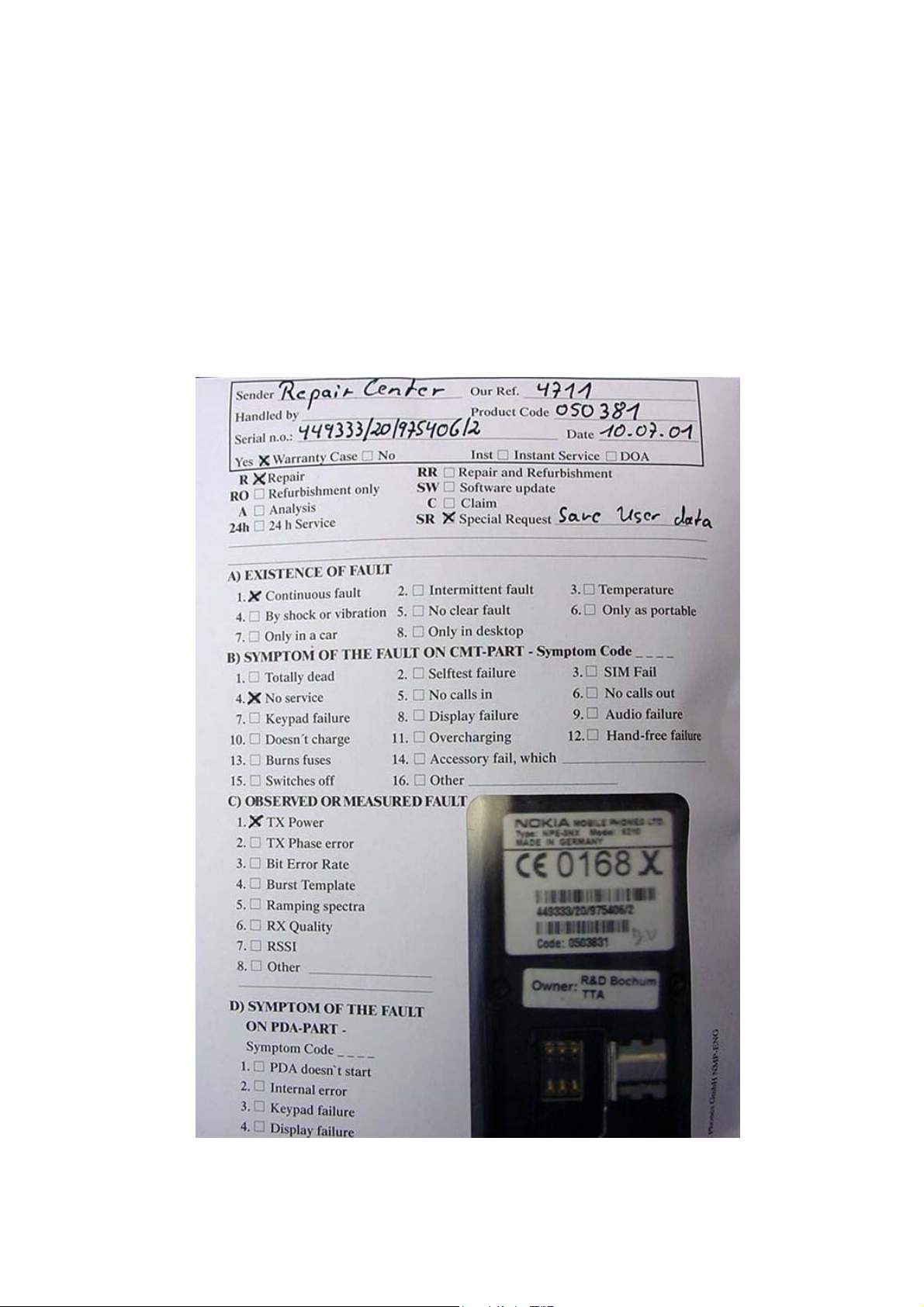
11. SERVICE NOTES
We recommend using Service Notes when shipping phones to other Service Partners. It
prevents the product from scratches, it is ESD-neutral and has the possibility to give
valuable feedback of the fault symptom through a structured form.
Please refer to the document Service Notes for faulty NMP transceiver on Partner Web
Site to get further information.
Service Manual 6800 Level 1&2 Copyright 2003 © Nokia Corporation
Page 23
nokia
CONNECTING PEOPLE
PAGE 23 (23) Approved 1.0
Nokia Mobile Phones Customer Care EMEA
Technical Services, Repair Concepts Confidential 20.03.2003
SQX 00618-en DJk
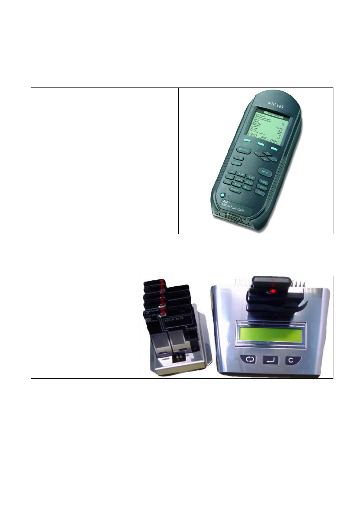
12. GONOGO TESTER
The will’tek GoNoGo Tester has to be used
to carry out the final test after your
service action to guarantee the
functionality of the phone.
Please refer to the actual information
in the Nokia Care Point Extranet within
the Partner Web Site.
13. BATTERY TESTER
The Astratec battery tester lets
you test the capacity of Nokia
batteries.
Please refer to the actual
information in the Nokia
Care Point Extranet within
the Partner Web Site.
Service Manual 6800 Level 1&2 Copyright 2003 © Nokia Corporation
 Loading...