

Page 1

Nokia Customer Care
Service Manual
RM-424; RM-564 (Nokia 6720 classic; L3&4)
Mobile Terminal
Part No: (Issue 1)
COMPANY CONFIDENTIAL
Copyright © 2009 Nokia. All rights reserved.
Page 2

Amendment Record Sheet
Amendment Record Sheet
Amendment No Date Inserted By Comments
Issue 1 04/2009 MT
RM-424; RM-564
Page ii COMPANY CONFIDENTIAL Issue 1
Copyright © 2009 Nokia. All rights reserved.
Page 3

RM-424; RM-564
Copyright
Copyright
Copyright © 2009 Nokia. All rights reserved.
Reproduction, transfer, distribution or storage of part or all of the contents in this document in any form
without the prior written permission of Nokia is prohibited.
Nokia, Nokia Connecting People, and Nokia X and Y are trademarks or registered trademarks of Nokia
Corporation. Other product and company names mentioned herein may be trademarks or tradenames of
their respective owners.
Nokia operates a policy of continuous development. Nokia reserves the right to make changes and
improvements to any of the products described in this document without prior notice.
Under no circumstances shall Nokia be responsible for any loss of data or income or any special, incidental,
consequential or indirect damages howsoever caused.
The contents of this document are provided "as is". Except as required by applicable law, no warranties of
any kind, either express or implied, including, but not limited to, the implied warranties of merchantability
and fitness for a particular purpose, are made in relation to the accuracy, reliability or contents of this
document. Nokia reserves the right to revise this document or withdraw it at any time without prior notice.
The availability of particular products may vary by region.
IMPORTANT
This document is intended for use by qualified service personnel only.
Issue 1 COMPANY CONFIDENTIAL Page iii
Copyright © 2009 Nokia. All rights reserved.
Page 4

RM-424; RM-564
Warnings and cautions
Warnings and cautions
Warnings
•
IF THE DEVICE CAN BE INSTALLED IN A VEHICLE, CARE MUST BE TAKEN ON INSTALLATION IN VEHICLES FITTED
WITH ELECTRONIC ENGINE MANAGEMENT SYSTEMS AND ANTI-SKID BRAKING SYSTEMS. UNDER CERTAIN FAULT
CONDITIONS, EMITTED RF ENERGY CAN AFFECT THEIR OPERATION. IF NECESSARY, CONSULT THE VEHICLE DEALER/
MANUFACTURER TO DETERMINE THE IMMUNITY OF VEHICLE ELECTRONIC SYSTEMS TO RF ENERGY.
•
THE PRODUCT MUST NOT BE OPERATED IN AREAS LIKELY TO CONTAIN POTENTIALLY EXPLOSIVE ATMOSPHERES,
FOR EXAMPLE, PETROL STATIONS (SERVICE STATIONS), BLASTING AREAS ETC.
•
OPERATION OF ANY RADIO TRANSMITTING EQUIPMENT, INCLUDING CELLULAR TELEPHONES, MAY INTERFERE
WITH THE FUNCTIONALITY OF INADEQUATELY PROTECTED MEDICAL DEVICES. CONSULT A PHYSICIAN OR THE
MANUFACTURER OF THE MEDICAL DEVICE IF YOU HAVE ANY QUESTIONS. OTHER ELECTRONIC EQUIPMENT MAY
ALSO BE SUBJECT TO INTERFERENCE.
•
BEFORE MAKING ANY TEST CONNECTIONS, MAKE SURE YOU HAVE SWITCHED OFF ALL EQUIPMENT.
Cautions
•
Servicing and alignment must be undertaken by qualified personnel only.
•
Ensure all work is carried out at an anti-static workstation and that an anti-static wrist strap is worn.
•
Ensure solder, wire, or foreign matter does not enter the telephone as damage may result.
•
Use only approved components as specified in the parts list.
•
Ensure all components, modules, screws and insulators are correctly re-fitted after servicing and
alignment.
•
Ensure all cables and wires are repositioned correctly.
•
Never test a mobile phone WCDMA transmitter with full Tx power, if there is no possibility to perform the
measurements in a good performance RF-shielded room. Even low power WCDMA transmitters may disturb
nearby WCDMA networks and cause problems to 3G cellular phone communication in a wide area.
•
During testing never activate the GSM or WCDMA transmitter without a proper antenna load, otherwise
GSM or WCDMA PA may be damaged.
Page iv COMPANY CONFIDENTIAL Issue 1
Copyright © 2009 Nokia. All rights reserved.
Page 5

RM-424; RM-564
For your safety
For your safety
QUALIFIED SERVICE
Only qualified personnel may install or repair phone equipment.
ACCESSORIES AND BATTERIES
Use only approved accessories and batteries. Do not connect incompatible products.
CONNECTING TO OTHER DEVICES
When connecting to any other device, read its user’s guide for detailed safety instructions. Do not connect
incompatible products.
Issue 1 COMPANY CONFIDENTIAL Page v
Copyright © 2009 Nokia. All rights reserved.
Page 6

RM-424; RM-564
ESD protection
ESD protection
Nokia requires that service points have sufficient ESD protection (against static electricity) when servicing
the phone.
Any product of which the covers are removed must be handled with ESD protection. The SIM card can be
replaced without ESD protection if the product is otherwise ready for use.
To replace the covers ESD protection must be applied.
All electronic parts of the product are susceptible to ESD. Resistors, too, can be damaged by static electricity
discharge.
All ESD sensitive parts must be packed in metallized protective bags during shipping and handling outside
any ESD Protected Area (EPA).
Every repair action involving opening the product or handling the product components must be done under
ESD protection.
ESD protected spare part packages MUST NOT be opened/closed out of an ESD Protected Area.
For more information and local requirements about ESD protection and ESD Protected Area, contact your local
Nokia After Market Services representative.
Page vi COMPANY CONFIDENTIAL Issue 1
Copyright © 2009 Nokia. All rights reserved.
Page 7

RM-424; RM-564
Care and maintenance
Care and maintenance
This product is of superior design and craftsmanship and should be treated with care. The suggestions below
will help you to fulfil any warranty obligations and to enjoy this product for many years.
•
Keep the phone and all its parts and accessories out of the reach of small children.
•
Keep the phone dry. Precipitation, humidity and all types of liquids or moisture can contain minerals that
will corrode electronic circuits.
•
Do not use or store the phone in dusty, dirty areas. Its moving parts can be damaged.
•
Do not store the phone in hot areas. High temperatures can shorten the life of electronic devices, damage
batteries, and warp or melt certain plastics.
•
Do not store the phone in cold areas. When it warms up (to its normal temperature), moisture can form
inside, which may damage electronic circuit boards.
•
Do not drop, knock or shake the phone. Rough handling can break internal circuit boards.
•
Do not use harsh chemicals, cleaning solvents, or strong detergents to clean the phone.
•
Do not paint the phone. Paint can clog the moving parts and prevent proper operation.
•
Use only the supplied or an approved replacement antenna. Unauthorised antennas, modifications or
attachments could damage the phone and may violate regulations governing radio devices.
All of the above suggestions apply equally to the product, battery, charger or any accessory.
Issue 1 COMPANY CONFIDENTIAL Page vii
Copyright © 2009 Nokia. All rights reserved.
Page 8

RM-424; RM-564
Company policy
Company policy
Our policy is of continuous development; details of all technical modifications will be included with service
bulletins.
While every endeavour has been made to ensure the accuracy of this document, some errors may exist. If
any errors are found by the reader, NOKIA MOBILE PHONES Business Group should be notified in writing/email.
Please state:
•
Title of the Document + Issue Number/Date of publication
•
Latest Amendment Number (if applicable)
•
Page(s) and/or Figure(s) in error
Please send to:
NOKIA CORPORATION
Nokia Mobile Phones Business Group
Nokia Customer Care
PO Box 86
FIN-24101 SALO
Finland
E-mail: Service.Manuals@nokia.com
Page viii COMPANY CONFIDENTIAL Issue 1
Copyright © 2009 Nokia. All rights reserved.
Page 9

RM-424; RM-564
Battery information
Battery information
Note: A new battery's full performance is achieved only after two or three complete charge and
discharge cycles!
The battery can be charged and discharged hundreds of times but it will eventually wear out. When the
operating time (talk-time and standby time) is noticeably shorter than normal, it is time to buy a new battery.
Use only batteries approved by the phone manufacturer and recharge the battery only with the chargers
approved by the manufacturer. Unplug the charger when not in use. Do not leave the battery connected to
a charger for longer than a week, since overcharging may shorten its lifetime. If left unused a fully charged
battery will discharge itself over time.
Temperature extremes can affect the ability of your battery to charge.
For good operation times with Li-Ion batteries, discharge the battery from time to time by leaving the product
switched on until it turns itself off (or by using the battery discharge facility of any approved accessory
available for the product). Do not attempt to discharge the battery by any other means.
Use the battery only for its intended purpose.
Never use any charger or battery which is damaged.
Do not short-circuit the battery. Accidental short-circuiting can occur when a metallic object (coin, clip or
pen) causes direct connection of the + and - terminals of the battery (metal strips on the battery) for example
when you carry a spare battery in your pocket or purse. Short-circuiting the terminals may damage the battery
or the connecting object.
Leaving the battery in hot or cold places, such as in a closed car in summer or winter conditions, will reduce
the capacity and lifetime of the battery. Always try to keep the battery between 15°C and 25°C (59°F and 77°
F). A phone with a hot or cold battery may temporarily not work, even when the battery is fully charged.
Batteries' performance is particularly limited in temperatures well below freezing.
Do not dispose of batteries in a fire!
Dispose of batteries according to local regulations (e.g. recycling). Do not dispose as household waste.
Issue 1 COMPANY CONFIDENTIAL Page ix
Copyright © 2009 Nokia. All rights reserved.
Page 10

RM-424; RM-564
Battery information
(This page left intentionally blank.)
Page x COMPANY CONFIDENTIAL Issue 1
Copyright © 2009 Nokia. All rights reserved.
Page 11

RM-424; RM-564
Nokia 6720 classic; L3&4 Service Manual Structure
Nokia 6720 classic; L3&4 Service Manual Structure
1 General Information
2 Service Tools and Service Concepts
3 BB Troubleshooting and Manual Tuning Guide
4 RF Troubleshooting
5 Camera Module Troubleshooting
6 System Module
7 Service information differences between RM-564 and RM-424
Glossary
Issue 1 COMPANY CONFIDENTIAL Page xi
Copyright © 2009 Nokia. All rights reserved.
Page 12

RM-424; RM-564
Nokia 6720 classic; L3&4 Service Manual Structure
(This page left intentionally blank.)
Page xii COMPANY CONFIDENTIAL Issue 1
Copyright © 2009 Nokia. All rights reserved.
Page 13

Nokia Customer Care
1 — General Information
Issue 1 COMPANY CONFIDENTIAL Page 1 –1
Copyright © 2009 Nokia. All rights reserved.
Page 14

RM-424; RM-564
General Information
(This page left intentionally blank.)
Page 1 –2 COMPANY CONFIDENTIAL Issue 1
Copyright © 2009 Nokia. All rights reserved.
Page 15

RM-424; RM-564
General Information
Table of Contents
Product selection....................................................................................................................................................1–5
Product features and sales package.....................................................................................................................1–6
Product and module list ........................................................................................................................................1–7
Mobile enhancements............................................................................................................................................1–8
Technical specifications...................................................................................................................................... 1–10
Transceiver general specifications ............................................................................................................... 1–10
Main RF characteristics for GSM850/900/1800/1900 and WCDMA VIII/II/I phones ................................. 1–10
Battery endurance.......................................................................................................................................... 1–11
Environmental conditions ............................................................................................................................. 1–12
List of Tables
Table 1 Audio..........................................................................................................................................................1–8
Table 2 Car...............................................................................................................................................................1–8
Table 3 Data ............................................................................................................................................................1–9
Table 4 Messaging..................................................................................................................................................1–9
Table 5 Music ..........................................................................................................................................................1–9
Table 6 Navigation .................................................................................................................................................1–9
Table 7 Power.........................................................................................................................................................1–9
List of Figures
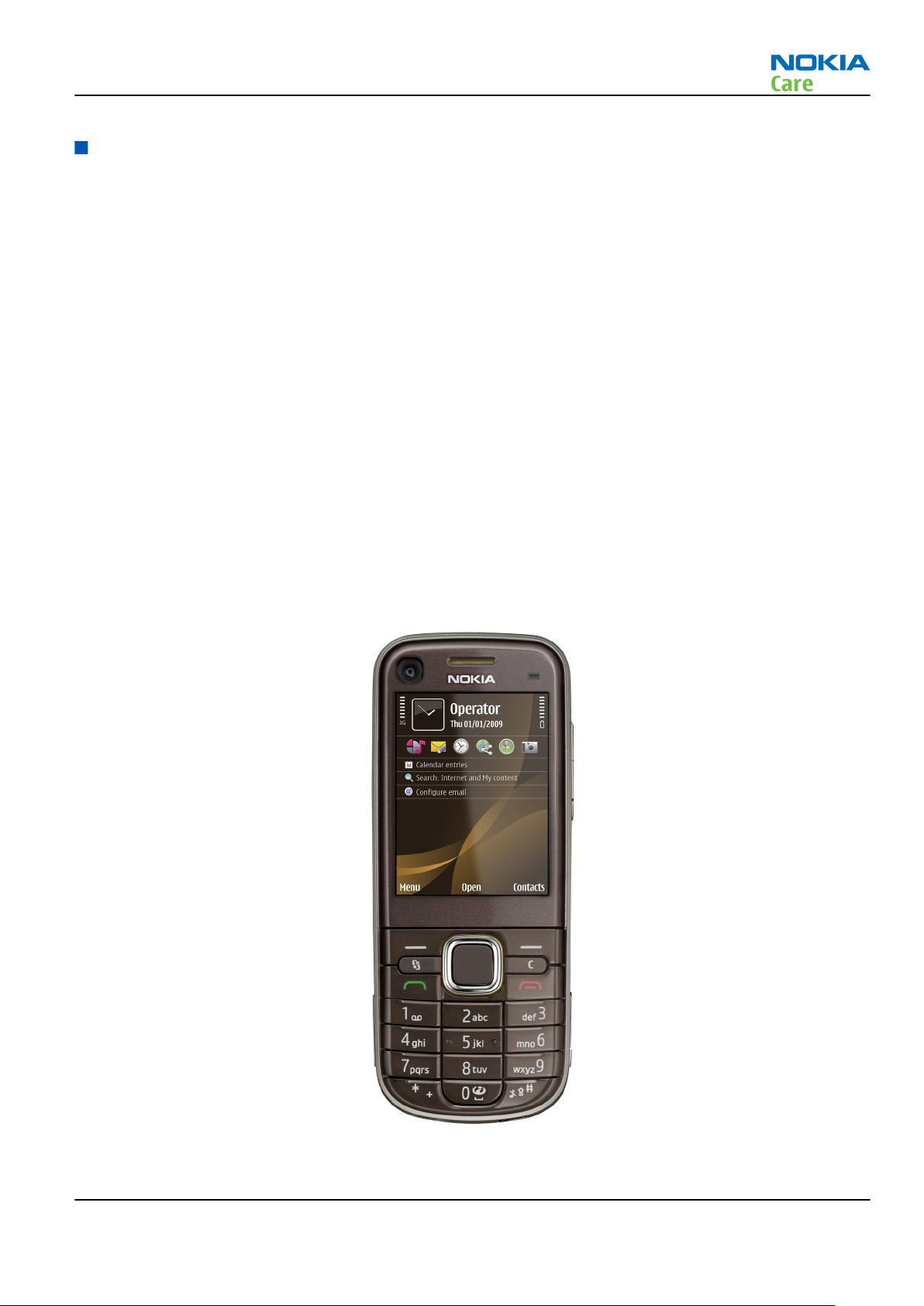
Figure 1 View of RM-424........................................................................................................................................1–5
Issue 1 COMPANY CONFIDENTIAL Page 1 –3
Copyright © 2009 Nokia. All rights reserved.
Page 16

RM-424; RM-564
General Information
(This page left intentionally blank.)
Page 1 –4 COMPANY CONFIDENTIAL Issue 1
Copyright © 2009 Nokia. All rights reserved.
Page 17
RM-424; RM-564
General Information
Product selection
RM-424 is a HSDPA/HSUPA/WCDMA/GSM handportable phone with a monoblock form factor, GPS (A-GPS)
support and a TV out connection. It supports EGSM850/900/1800/1900 and WCDMA900/1900/2100 bands,
and CSD/HSCSD, GPRS/EGPRS, WCDMA/HSDPA/HSUPA data bearers.
For WCDMA the maximum bit rate is up to 384 kbit/s for downlink and 384 kbit/s for uplink with simultaneous
CS speech or CS video (max. 64 kbit/s). The HSDPA peak is 10.2Mbps and HSUPA peak is 2Mbps (with limited
use cases).
In PS/CS mode, RM-424 supports DTM Class with multi slot class 11 (max. 4 RX + 3TX, sum 5). With EGPRS this
means maximum download speed of up to 236.8 kbit/s simultaneously with speech. With GPRS this means
maximum download speed of up to 64.2 kbit/s simultaneously with speech.
In PS only mode, RM-424 supports MSC 32 (max. 5 Rx + 3 TX, sum 6) timeslots resulting in maximum download
speed of up to 296kbit/s with EGPRS, and up to 107kbit/s with GPRS
RM-424 is an MMS (Multimedia Messaging Service) enabled multimedia device. The MMS implementation
follows the OMA MMS standard release 1.2. RM-424 also supports Bluetooth 2.0 standard with the stereo
audio profiles (A2DP & AVRCP).
RM-424 has a large 2.2’’ QVGA (320 x 240 pixels) TFT display with 16 million colors, a 5 Megapixel main camera
that has Carl Zeiss autofocus lens, an integrated dual flash, autofocus light, video light and a video recording
indicator. The 2nd camera is for video calls, but can also be used for still imaging and video recording.
RM-424 uses Symbian 9.3 operating system, S60 (release 3.2) UI, and it supports the full Web Browser for
S60, which brings desktop-like Web browsing experience to mobile devices.
RM-424 also supports MIDP Java 2.0, providing a good platform for compelling 3rd party applications.
Figure 1 View of RM-424
Issue 1 COMPANY CONFIDENTIAL Page 1 –5
Copyright © 2009 Nokia. All rights reserved.
Page 18

Product features and sales package
Bearers and transport
•
CSD, HSCSD
•
GPRS/EGPRS Class B, Multi slot class 32
•
Dual Transfer Mode (DTM) class A, multi slot class 11
•
WCDMA DL 384kbit/s, UL 384 kbit/s
•
HSDPA up to 10.2Mbps
•
HSUPA 2Mbps
Connectivity
•
GPS (with A-GPS support)
•
TV out
•
Bluetooth 2.0 with stereo audio profiles (A2DP and AVRCP)
•
High Speed USB with micro USB connector
•
MicroSD memory card - support up to 8GB
•
3.5 mm AV Connector
•
2.0 mm DC jack
RM-424; RM-564
General Information
Display
•
Large 2.2’’ QVGA (320 x 240 pixels) TFT display with 16 million colors
•
Digital Ambient Light Sensor (ALS) – used to optimize display/key brightness and power consumption
•
Orientation sensor (accelerometer) assisted UI turn (portrate / landscape) and turn-to-mute
Imaging and video
•
5 Megapixel with Carl Zeiss autofocus lens, integrated dual Flash, autofocus light and video recording
indicator
•
2nd camera for video calls, but also for still imaging and video recording
•
Video streaming and sharing
•
Dedicated keys for image capture, recording and zooming
•
Image and video editors
Music
•
Music player with MP3/AAC/AAC+/eAAC+/WMA support
•
Active noise cancellation (eANC for downlink and 2- MIC noise cancellation for uplink)
•
Speech codec support for AMR-WB, AMR, FR, EFR
•
Stereo speaker
•
RDS FM Radio
Productivity
Context management
•
OMA DRM version 2.0
•
PIM (Calendar + Contacts + Active Notes)
Page 1 –6 COMPANY CONFIDENTIAL Issue 1
Copyright © 2009 Nokia. All rights reserved.
Page 19
RM-424; RM-564
General Information
•
OTA provisioning & over the air SW update (FOTA)
•
Ovi Suite
•
Active Standby
•
Active Synch data synchronization
•
Web Browser (OSS), Java ™ MIDP 2.0, XHTML browsing over TCP/IP
Messaging
•
Email (SMTP, IMAP4, POP3)
•
SMS, MMS (OMA 1.3)
•
Audio Messaging (AMS)
Voice
•
Rich Calls: 2-way video conferencing (video call), video sharing
•
Voice commands, enhanced voice dialling (SIND)
•
Audio message reader for text messages and E-mail
•
VoIP calls
Add-on software framework
•
Symbian OS 9.3
•
Nokia Series 60, 3rd edition, feature pack 3.2
•
Java: MIDP2.0
Additional features
•
City compass to support easy pedestrian routing and guidance
•
Battery status LED around DC jack to indicate low battery and charging status
•
Status LED light around navi-key to indicate events like missed call, SMS etc.
•
Vibrating alert
•
Speech codec support for AMR-WB, AMR, FR, EFR
Basic sales package
Basic sales package, there may be sales area variations.
•
Transceiver RM-424
•
Battery (BP-6MT/1050mAh)
•
Charger AC-8
•
Stereo headset (HS-125)
•
Short micro USB connectivity cable (CA-101D)
•
MicroSD card 1GB (MU-22)
•
Mini-DVD (Ovi Suite)
•
Short user guide
Product and module list
Module name Type code Notes
System/RF module PWB 2QM
Issue 1 COMPANY CONFIDENTIAL Page 1 –7
Copyright © 2009 Nokia. All rights reserved.
Page 20
Module name Type code Notes
Flash flex 2QF
eANC flex 2QG
Key UI flex 2QH
System connector flex 2QJ
Mobile enhancements
Table 1 Audio
Enhancement Type
Headsets (stereo) HS-45 + AD-54 (inbox)
WH-500
WH-600
Wireless headsets (BT stereo) BH-503
BH-504
RM-424; RM-564
General Information
Table 2 Car
Enhancement Type
Car navigation Nokia 500 Auto Navigation
Car kit CK-7W
CK-15W
CK-100
CK-300 (BT & plug-in)
CK-600
FM transmitter CA-300
Holder CR-39
CR-82
CR-99
Mobile charger DC-4
Mobile holder easy mount HH-12
HH-17
Plug-in car handsfree HF-200
HF-300
HF-310
HF-510
Page 1 –8 COMPANY CONFIDENTIAL Issue 1
Copyright © 2009 Nokia. All rights reserved.
Page 21
RM-424; RM-564
General Information
Table 3 Data
Enhancement Type
MicroSD card, 512MB MU-28
MicroSD card, 1GB MU-22
MicroSD card, 2GB MU-37
MicroSD card, 4GB MU-41
MicroSD card, 8GB MU-43
MicroSD card, 16GB MU-44
Micro USB connectivity adapter cable CA-101/CA_101D
Table 4 Messaging
Enhancement Type
Digital pen SU-27W
Wireless keyboard SU-8W
Table 5 Music
Enhancement Type
Bluetooth speakers MD-5W (BT & plug-in)
MD-7W (BT & plug-in)
Music speakers MD-6
MD-8
Table 6 Navigation
Enhancement Type
Wireless GPS module LD-3W
LD-4W
Table 7 Power
Enhancement Type
Battery 1050mAh Li-ion BP-6MT
Charger adapter DT-14
Issue 1 COMPANY CONFIDENTIAL Page 1 –9
Copyright © 2009 Nokia. All rights reserved.
Page 22
Enhancement Type
Charger AC-5
Technical specifications
Transceiver general specifications
RM-424; RM-564
General Information
AC-8
DC-8
DC-9
DC-11
Unit Dimensions (L x W x T)
Transceiver with
BP-6MT 1050mAh Li-ion
battery back
(mm)
110 x 45 x 14 110 64
Weight (g)
Volume (cm3)
Main RF characteristics for GSM850/900/1800/1900 and WCDMA VIII/II/I phones
Parameter Unit
Cellular system GSM850, EGSM900, GSM1800/1900, WCDMA VIII
(900), WCDMA II (1900) and WCDMA I (2100)
Rx frequency band GSM850: 869 - 894 MHz
EGSM900: 925 - 960 MHz
GSM1800: 1805 - 1880 MHz
GSM1900: 1930 - 1990 MHz
WCDMA VIII (900): 925- 960 MHz
WCDMA II (1900): 1930-1990MHz
WCDMA I (2100): 2110 - 2170 MHz
Tx frequency band GSM850: 824 - 849 MHz
EGSM900: 880 - 915 MHz
GSM1800: 1710 - 1785 MHz
GSM1900: 1850 - 1910 MHz
WCDMA VIII (900): 880 - 915 MHz
WCDMA II (1900): 1850-1910MHz
WCDMA I (2100): 1920 - 1980 MHz
Page 1 –10 COMPANY CONFIDENTIAL Issue 1
Copyright © 2009 Nokia. All rights reserved.
Page 23

RM-424; RM-564
General Information
Parameter Unit
Output power GSM850: +5 ...+33dBm/3.2mW ... 2W
GSM900: +5 … +33dBm/3.2mW … 2W
GSM1800: +0 … +30dBm/1.0mW … 1W
GSM1900: +0 … +30dBm/1.0mW … 1W
WCDMA VIII (900): -50 ... +24 dBm/0.01μW ...
251.2mW
WCDMA II (1900): -50 ... +24dBm/0.01µW ...
251.2mW
WCDMA I (2100): -50 ... +24 dBm/0.01μW ...
251.2mW
EDGE output power EDGE850: +5 … +29dBm/3.2mW … 794mW
EDGE900: +5 … +29dBm/3.2mW … 794mW
EDGE1800: +0 … +26dBm/1.0mW … 400mW
EDGE1900:+0 … +26dBm/1.0mW … 400mW
Number of RF channels GSM850: 124
GSM900: 174
GSM1800: 374
GSM1900: 299
WCDMA VIII (900): 152
WCDMA II (1900): 289
WCDMA I (2100): 277
Channel spacing 200 kHz (WCDMA II 100/200 kHz)
Number of Tx power levels GSM850: 15
GSM900: 15
GSM1800: 16
GSM1900: 16
WCDMA VIII (900): 75
WCDMA II (1900): 75
WCDMA I (2100): 75
Battery endurance
Battery Capacity (mAh) Talk time Stand-by
BP-6MT 1050 Up to 7.1 h (GSM)
Up to 4.3 h (WCDMA)
Issue 1 COMPANY CONFIDENTIAL Page 1 –11
Copyright © 2009 Nokia. All rights reserved.
Up to 525 h (GSM)
Up to 404 h (WCDMA)
Page 24
Environmental conditions
Temperature conditions
Environmental condition Ambient temperature Notes
RM-424; RM-564
General Information
Normal operation
Reduced performance
Intermittent operation
No operation or storage
Charging allowed
Long term storage conditions
-15oC...+55oC
-25oC...-15oC
+55oC...+70oC
-40oC...-15oC
+70oC...+85 oC
<-40oC...>+85oC
-25oC...+50oC
0oC...+85oC
Specifications fulfilled
Operational for shorts periods
only
Operation not guaranteed but an
attempt to operate does not
damage the phone.
No storage or operation: an
attempt may damage the phone.
Humidity
Relative humidity range is 5...95%.
The HW module is not protected against water. Condensed or splashed water might cause malfunction. Any
submerge of the phone will cause permanent damage. Long-term high humidity, with condensation, will
cause permanent damage because of corrosion.
Vibration
The module should withstand the following vibrations:
•
5 - 10 Hz; +10dB / octave
•
10 - 50 Hz; 5.58 m2 / s3 (0.0558 g2/ Hz)
•
50 - 300 Hz; - 10 dB / octave
ESD strength
Conducted discharge is 8 kV (>10 discharges) and air contact 15 kV ( >10 discharges ).
The standard for electrostatic discharge is IEC 61000-4-2, and this device fulfils level 4 requirements.
RoHS
This device uses RoHS compliant components and lead-free soldering process.
Page 1 –12 COMPANY CONFIDENTIAL Issue 1
Copyright © 2009 Nokia. All rights reserved.
Page 25

Nokia Customer Care
2 — Service Tools and Service
Concepts
Issue 1 COMPANY CONFIDENTIAL Page 2 –1
Copyright © 2009 Nokia. All rights reserved.
Page 26

RM-424; RM-564
Service Tools and Service Concepts
(This page left intentionally blank.)
Page 2 –2 COMPANY CONFIDENTIAL Issue 1
Copyright © 2009 Nokia. All rights reserved.
Page 27

RM-424; RM-564
Service Tools and Service Concepts
Table of Contents
Service tools............................................................................................................................................................2–5
Product specific tools........................................................................................................................................2–5
FS-97..............................................................................................................................................................2–5
MJ-191 ...........................................................................................................................................................2–5
RJ-230 ............................................................................................................................................................2–5
SA-131 ...........................................................................................................................................................2–5
SA-157 ...........................................................................................................................................................2–6
Using SA-131 GPS RF coupler with RM-424................................................................................................2–6
Rework jigs and stencils...................................................................................................................................2–8
RJ-160 ............................................................................................................................................................2–8
RJ-227 ............................................................................................................................................................2–9
RJ-228 ............................................................................................................................................................2–9
RJ-73 ..............................................................................................................................................................2–9
RJ-93 ..............................................................................................................................................................2–9
ST-29..............................................................................................................................................................2–9
ST-40..............................................................................................................................................................2–9
ST-55........................................................................................................................................................... 2–10
ST-70........................................................................................................................................................... 2–10
ST-71........................................................................................................................................................... 2–10
General tools................................................................................................................................................... 2–10
AC-33........................................................................................................................................................... 2–10
AC-35........................................................................................................................................................... 2–10
CU-4............................................................................................................................................................. 2–11
FLS-5 ........................................................................................................................................................... 2–12
FPS-10......................................................................................................................................................... 2–12
FPS-21......................................................................................................................................................... 2–13
JXS-1............................................................................................................................................................ 2–13
PK-1............................................................................................................................................................. 2–14
PKD-1 .......................................................................................................................................................... 2–14
SB-6............................................................................................................................................................. 2–14
SPS-1........................................................................................................................................................... 2–14
SPS-2........................................................................................................................................................... 2–15
SRT-6........................................................................................................................................................... 2–15
SS-100......................................................................................................................................................... 2–15
SS-46........................................................................................................................................................... 2–15
SS-62........................................................................................................................................................... 2–15
SS-93........................................................................................................................................................... 2–15
SX-4............................................................................................................................................................. 2–16
Cables............................................................................................................................................................... 2–16
CA-101 ........................................................................................................................................................ 2–16
CA-31D ........................................................................................................................................................ 2–16
CA-35S......................................................................................................................................................... 2–17
CA-58RS....................................................................................................................................................... 2–17
CA-89DS ...................................................................................................................................................... 2–17
DAU-9S........................................................................................................................................................ 2–18
PCS-1........................................................................................................................................................... 2–18
XCS-4........................................................................................................................................................... 2–18
XRS-6........................................................................................................................................................... 2–19
Service concepts .................................................................................................................................................. 2–19
POS (Point of Sale) flash concept .................................................................................................................. 2–19
Issue 1 COMPANY CONFIDENTIAL Page 2 –3
Copyright © 2009 Nokia. All rights reserved.
Page 28

RM-424; RM-564
Service Tools and Service Concepts
Flash concept with FPS-10............................................................................................................................. 2–20
Flash concept with FPS-21............................................................................................................................. 2–21
CU-4 flash concept with FPS-10..................................................................................................................... 2–22
CU-4 flash concept with FPS-21..................................................................................................................... 2–23
Module jig service concept............................................................................................................................ 2–24
RF testing concept with RF coupler .............................................................................................................. 2–25
RF testing / BB tuning concept...................................................................................................................... 2–26
BB/RF tuning concept with module jig ........................................................................................................ 2–27
Bluetooth testing concept with SB-6 ........................................................................................................... 2–28
GPS testing concept with GPS RF coupler..................................................................................................... 2–29
List of Tables
Table 8 Attenuation values ................................................................................................................................ 2–17
List of Figures
Figure 2 Base setting for SA-131...........................................................................................................................2–7
Figure 3 Coupler setting for SA-131......................................................................................................................2–8
Figure 4 POS flash concept ................................................................................................................................. 2–19
Figure 5 Basic flash concept with FPS-10.......................................................................................................... 2–20
Figure 6 Basic flash concept with FPS-21.......................................................................................................... 2–21
Figure 7 CU-4 flash concept with FPS-10........................................................................................................... 2–22
Figure 8 CU-4 flash concept with FPS-21........................................................................................................... 2–23
Figure 9 Module jig service concept .................................................................................................................. 2–24
Figure 10 RF testing concept with RF coupler.................................................................................................. 2–25
Figure 11 RF testing / BB tuning concept ......................................................................................................... 2–26
Figure 12 Service concept for RF testing and RF/BB tuning............................................................................ 2–28
Figure 13 RF testing concept with RF coupler.................................................................................................. 2–29
Page 2 –4 COMPANY CONFIDENTIAL Issue 1
Copyright © 2009 Nokia. All rights reserved.
Page 29
RM-424; RM-564
Service Tools and Service Concepts
Service tools
Product specific tools
The table below gives a short overview of service devices that can be used for testing, error analysis, and
repair of product RM-424; RM-564. For the correct use of the service devices, and the best effort of workbench
setup, please refer to various concepts.
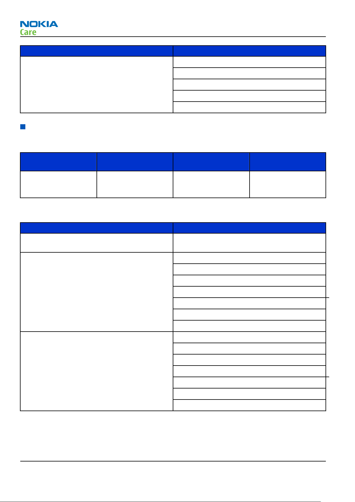
FS-97 Flash adapter For flashing (also dead phones) with SS-46. RF testing (with RF
coupler), and EM calibration on ATO level with SS-62 (mechanical
locking concept), CU-4 supported.
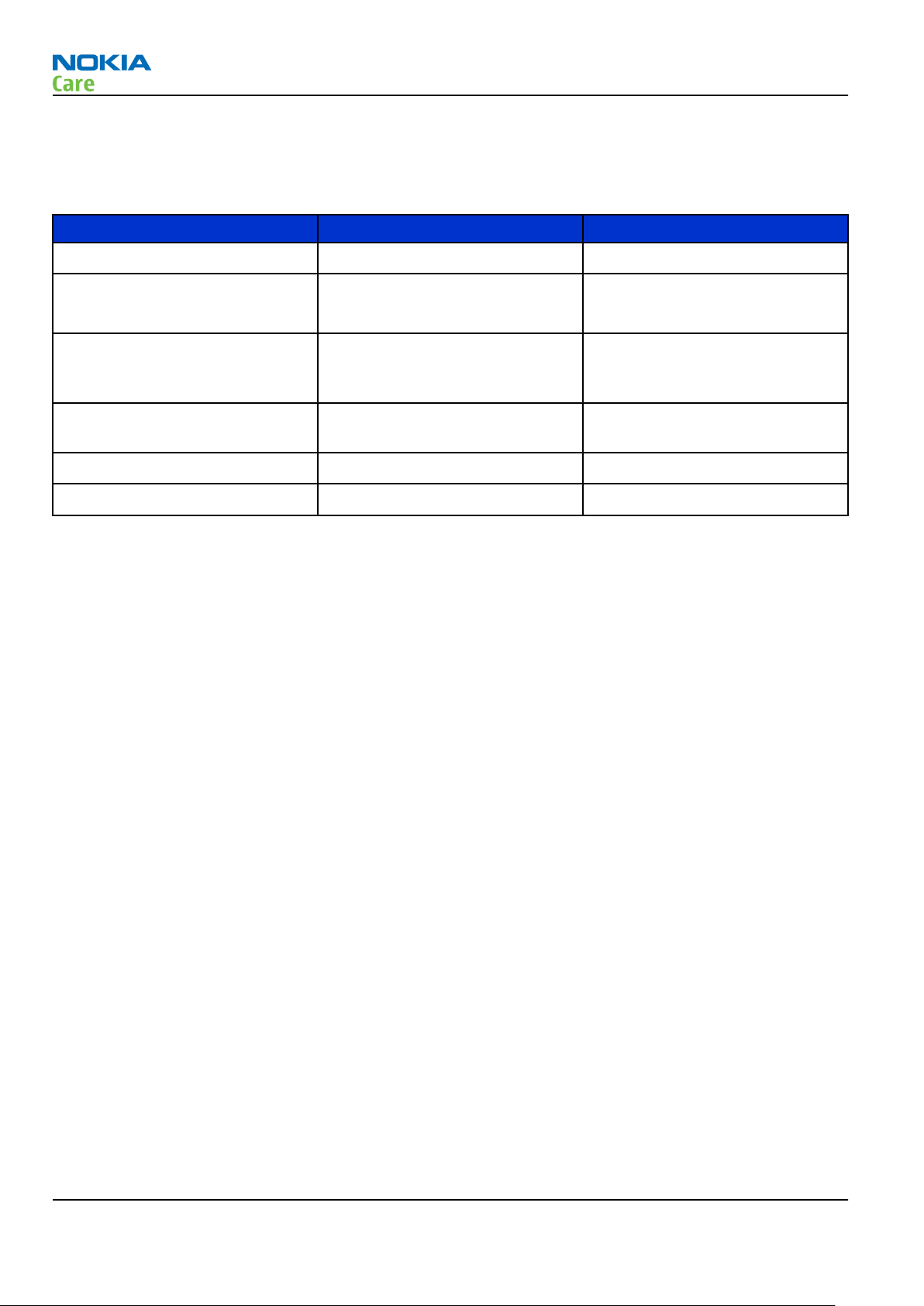
MJ-191 Module jig MJ-191 is meant for troubleshooting, testing, tuning and flashing on
the engine level (CU-4 supported).
The jig includes an RF interface for GSM, WCDMA, Bluetooth and GPS.
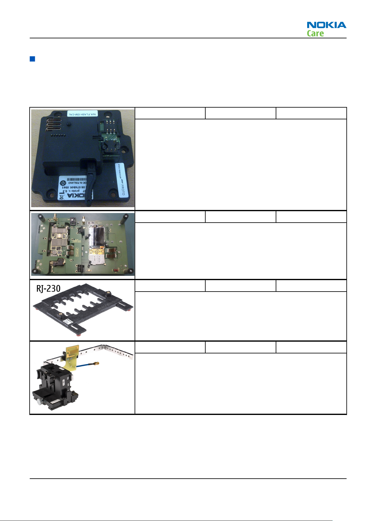
RJ-230 Soldering jig RJ-230 is a soldering jig used for soldering and as a rework jig for the
engine module.
SA-131 RF coupler SA-131 is a generic device for GPS testing. It is used together with
SS-62.
Issue 1 COMPANY CONFIDENTIAL Page 2 –5
Copyright © 2009 Nokia. All rights reserved.
Page 30
RM-424; RM-564
Service Tools and Service Concepts
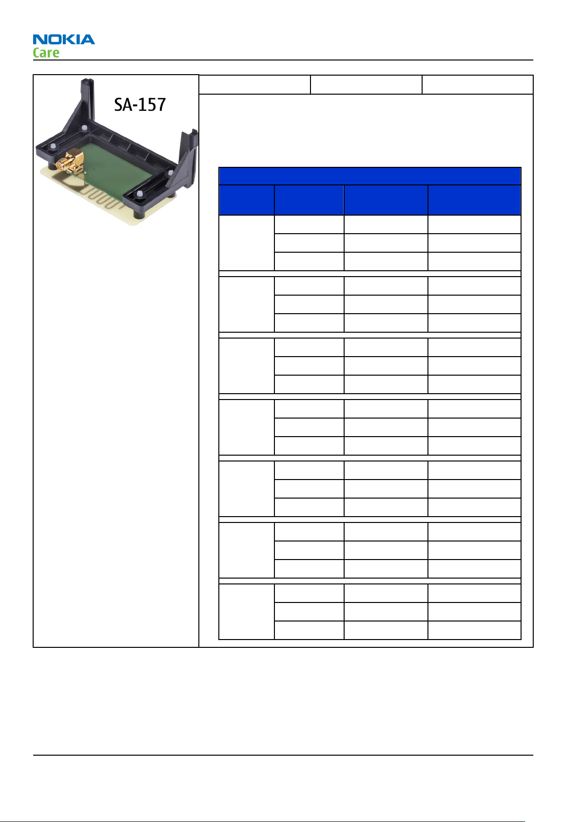
SA-157 RF coupler SA-157 is an RF coupler for WCDMA and GSM RF testing. It is used
together with the product-specific flash adapter.
The following table shows attenuations from the antenna pads of the
mobile terminal to the SMA connectors of SA-157 . The setup used for
measuring the values is SA-157 + FS-97 + SS-62 + CU-4.
•
Attenuation values for inductive RF coupler SA-157
Band Channel Attenuation RX
(dB)
Low 7.7 11.4
GSM 850
GSM 900
GSM
1800
GSM
1900
WCDMA
Band I
Mid 7.8 10.5
High 6.5 8.8
Low 5.7 7.3
Mid 6.7 7.4
High 5.8 6.7
Low 13.9 15.0
Mid 12.8 14.1
High 15.7 12.8
Low 13.3 13.6
Mid 13.5 14.1
High 14.0 13.2
Low 17.1 12.8
Mid 18.0 13.3
High 18.2 12.6
Attenuation TX
(dB)
Low 13.6 12.9
WCDMA
Band II
WCDMA
Band VIII
Mid 13.0 13.4
High 14.4 13.1
Low 6.3 8.0
Mid 7.1 7.5
High 6.5 6.9
Using SA-131 GPS RF coupler with RM-424
Use the following basic SA-131 setup for RM-424:
•
1575.520152 MHz
•
-110dbm
•
20db fixed RF attenuator
Page 2 –6 COMPANY CONFIDENTIAL Issue 1
Copyright © 2009 Nokia. All rights reserved.
Page 31

RM-424; RM-564
Service Tools and Service Concepts
•
12 db product specific RF attenuation
And use the following settings for the SA-131:
•
Base setting: 2
•
Sledge setting: 2
•
Frame setting: A1
•
Coupler setting: A2
•
Direction: Down
Figure 2 Base setting for SA-131
Issue 1 COMPANY CONFIDENTIAL Page 2 –7
Copyright © 2009 Nokia. All rights reserved.
Page 32

RM-424; RM-564
Service Tools and Service Concepts
Figure 3 Coupler setting for SA-131
Rework jigs and stencils
The table below gives a short overview of service devices that can be used for testing, error analysis, and
repair of product RM-424; RM-564. For the correct use of the service devices, and the best effort of workbench
setup, please refer to various concepts.
RJ-160 Rework jig RJ-160 is a rework jig used when servicing the WCDMA duplexer
(Z7540). It is used together with the ST-55 stencil.
Page 2 –8 COMPANY CONFIDENTIAL Issue 1
Copyright © 2009 Nokia. All rights reserved.
Page 33

RM-424; RM-564
Service Tools and Service Concepts
RJ-227 Rework jig RJ-227 is a rework jig used when servicing the BTHFM module (D6000).
It is used together with the ST-70 rework stencil.
RJ-228 Rework jig RJ-228 is a rework jig used when servicing the WCDMA PA (N7540)
component. It is used together with the ST-71 stencil.
RJ-73 Rework jig RJ-73 is a rework jig used when servicing the N1400 component. It is
used together with the ST-29 rework stencil.
RJ-93 Rework jig RJ-93 is used as a rework jig for the Front End Module (FEM).
This rework jig takes the FEM or power amplifier (PA) module (N7520)
for spreading the soldering paste to the component. Must be used
together with the ST-40 stencil.
ST-29 rework stencil ST-29 is a rework stencil used when servicing the N1400 component.
It is used together with rework jig RJ-73.
ST-40 Rework stencil ST-40 is a rework stencil that is used with the RJ-93 rework jig to
service the Front End Module (N7520).
Issue 1 COMPANY CONFIDENTIAL Page 2 –9
Copyright © 2009 Nokia. All rights reserved.
Page 34

RM-424; RM-564
Service Tools and Service Concepts
ST-55 Rework stencil ST-55 is a rework stencil used when servicing the Z7540 and Z7541
duplexers. It is used together with the rework jigs RJ-157 and RJ-160.
ST-70 Rework stencil ST-70 rework stencil is used with RJ-227 rework jig to service the
BTHFM module (D6000).
ST-71 Rework stencil ST-71 is a rework stencil used when servicing the WCDMA PA (N7540)
component. It is used together with rework jig RJ-228.
General tools
The table below gives a short overview of service devices that can be used for testing, error analysis, and
repair of product RM-424; RM-564. For the correct use of the service devices, and the best effort of workbench
setup, please refer to various concepts.
AC-33 Power supply Universal power supply for FPS-10; included in the FPS-10 sales
package.
AC-35 Power supply Universal power supply for FPS-21; included in the FPS-21 sales
package. Also available as a separate spare part.
Input 100V…230V 50Hz…60Hz, output voltage of 12 V and output
current up to 3 A.
Page 2 –10 COMPANY CONFIDENTIAL Issue 1
Copyright © 2009 Nokia. All rights reserved.
Page 35

RM-424; RM-564
Service Tools and Service Concepts
CU-4 Control unit CU-4 is a general service tool used with a module jig and/or a flash
adapter. It requires an external 12 V power supply.
The unit has the following features:
•
software controlled via USB
•
EM calibration function
•
Forwards FBUS/Flashbus traffic to/from terminal
•
Forwards USB traffic to/from terminal
•
software controlled BSI values
•
regulated VBATT voltage
•
2 x USB2.0 connector (Hub)
•
FBUS and USB connections supported
When using CU-4, note the special order of connecting cables and
other service equipment:
Instructions
1 Connect a service tool (jig, flash adapter) to CU-4.
2 Connect CU-4 to your PC with a USB cable.
3 Connect supply voltage (12 V)
4 Connect an FBUS cable (if necessary).
5 Start Phoenix service software.
Note: Phoenix enables CU-4 regulators via USB when it is
started.
Reconnecting the power supply requires a Phoenix restart.
Issue 1 COMPANY CONFIDENTIAL Page 2 –11
Copyright © 2009 Nokia. All rights reserved.
Page 36

RM-424; RM-564
Service Tools and Service Concepts
FLS-5 Flash device FLS-5 is a dongle and flash device incorporated into one package,
developed specifically for POS use.
Note: FLS-5 can be used as an alternative to PKD-1.
FPS-10 Flash prommer FPS-10 interfaces with:
•
PC
•
Control unit
•
Flash adapter
•
Smart card
FPS-10 flash prommer features:
•
Flash functionality for BB5 and DCT-4 terminals
•
Smart Card reader for SX-2 or SX-4
•
USB traffic forwarding
•
USB to FBUS/Flashbus conversion
•
LAN to FBUS/Flashbus and USB conversion
•
Vusb output switchable by PC command
FPS-10 sales package includes:
•
FPS-10 prommer
•
Power Supply with 5 country specific cords
•
USB cable
Note: FPS-21 is substitute FPS-10 if FPS-10 has not been set
up.
Note: FPS-10 is not available anymore.
Page 2 –12 COMPANY CONFIDENTIAL Issue 1
Copyright © 2009 Nokia. All rights reserved.
Page 37

RM-424; RM-564
Service Tools and Service Concepts
FPS-21 Flash prommer
FPS-21 sales package:
•
FPS-21 prommer
•
AC-35 power supply
•
CA-31D USB cable
FPS-21 interfaces:
Front
•
Service cable connector
Provides Flashbus, USB and VBAT connections to a mobile device.
•
SmartCard socket
A SmartCard is needed to allow DCT-4 generation mobile device
programming.
Rear
•
DC power input
For connecting the external power supply (AC-35).
•
Two USB A type ports (USB1/USB3)
Can be used, for example, for connecting external storage memory
devices or mobile devices
•
One USB B type device connector (USB2)
For connecting a PC.
•
Phone connector
Service cable connection for connecting Flashbus/FLA.
•
Ethernet RJ45 type socket (LAN)
For connecting the FPS-21 to LAN.
Inside
•
Four SD card memory slots
For internal storage memory.
Note: In order to access the SD memory card slots inside
FPS-21, the prommer needs to be opened by removing the
front panel, rear panel and heatsink from the prommer body.
Note: FPS-10 can be used for flashing instead of FPS-21 if
necessary.
JXS-1 RF shield box Because the WCDMA network disturbs the RX side testing of the WCDMA
phone and the Tx signal of the WCDMA phone can severely disturb the
WCDMA network, a shield box is needed in all testing, tuning and fault
finding which requires WCDMA RF signal.
The shield box is not an active device, it contains only passive filtering
components for RF attenuation.
Issue 1 COMPANY CONFIDENTIAL Page 2 –13
Copyright © 2009 Nokia. All rights reserved.
Page 38

RM-424; RM-564
Service Tools and Service Concepts
PK-1 Software protection
key
PK-1 is a hardware protection key with a USB interface. It has the same
functionality as the PKD-1 series dongle.
PK-1 is meant for use with a PC that does not have a series interface.
To use this USB dongle for security service functions please register
the dongle in the same way as the PKD-1 series dongle.
PKD-1 SW security device
SW security device is a piece of hardware enabling the use of the
service software when connected to the parallel (LPT) port of the PC.
Without the device, it is not possible to use the service software.
Printer or any such device can be connected to the PC through the
device if needed.
SB-6 Bluetooth test and
interface box (sales
package)
The SB-6 test box is a generic service device used to perform Bluetooth
bit error rate (BER) testing, and establishing cordless FBUS connection
via Bluetooth. An ACP-8x charger is needed for BER testing and an
AXS-4 cable in case of cordless interface usage testing .
Sales package includes:
•
SB-6 test box
•
Installation and warranty information
SPS-1 Soldering Paste
Spreader
The SPS-1 allows spreading of solder to the LGA components pads over
the rework stencils.
Note: Existing solder paste stencils and component holder
jigs will be supported until January 2009. For all new parts
needing solder paste support after January 1, 2009, please
contact your solder machine manufacturer for the universal
solutions for solder paste application for rework purposes.
Page 2 –14 COMPANY CONFIDENTIAL Issue 1
Copyright © 2009 Nokia. All rights reserved.
Page 39

RM-424; RM-564
Service Tools and Service Concepts
SPS-2 Soldering paste
spreader
Note: Existing solder paste stencils and component holder
jigs will be supported until January 2009. For all new parts
needing solder paste support after January 1, 2009, please
contact your solder machine manufacturer for the universal
solutions for solder paste application for rework purposes.
SRT-6 Opening tool SRT-6 is used to open phone covers.
Note: The SRT-6 is included in the Nokia Standard Toolkit.
SS-100 Camera removal tool The camera removal tool SS-100 is used to remove/attach a camera
module from/to the camera socket of the phone PWB.
SS-46 Interface adapter SS-46 acts as an interface adapter between the flash adapter and
FPS-10.
SS-62 Generic flash adapter
base for BB5
•
generic base for flash adapters and couplers
•
SS-62 equipped with a clip interlock system
•
provides standardised interface towards Control Unit
•
provides RF connection using galvanic connector or coupler
•
multiplexing between USB and FBUS media, controlled by VUSB
SS-93 Opening tool SS-93 is used for opening JAE connectors.
Note: The SS-93 is included in Nokia Standard Toolkit.
Issue 1 COMPANY CONFIDENTIAL Page 2 –15
Copyright © 2009 Nokia. All rights reserved.
Page 40

RM-424; RM-564
Service Tools and Service Concepts
SX-4 Smart card SX-4 is a BB5 security device used to protect critical features in tuning
and testing.
SX-4 is also needed together with FPS-10 when DCT-4 phones are
flashed.
Cables
The table below gives a short overview of service devices that can be used for testing, error analysis, and
repair of product RM-424; RM-564. For the correct use of the service devices, and the best effort of workbench
setup, please refer to various concepts.
CA-101 Micro USB cable The CA-101 is a USB-to-microUSB data cable that allows connections
between the PC and the phone.
CA-31D USB cable The CA-31D USB cable is used to connect FPS-10 or FPS-11 to a PC. It is
included in the FPS-10 and FPS-11 sales packages.
Page 2 –16 COMPANY CONFIDENTIAL Issue 1
Copyright © 2009 Nokia. All rights reserved.
Page 41

RM-424; RM-564
Service Tools and Service Concepts
CA-35S Power cable CA-35S is a power cable for connecting, for example, the FPS-10 flash
prommer to the Point-Of-Sales (POS) flash adapter.
CA-58RS RF tuning cable Product-specific adapter cable for RF tuning.
•
Table 8 Attenuation values
Band Attenuation Rx/Tx
GSM850/900 0.2...0.3 dB
GSM1800/1900 0.3...0.4 dB
WCDMA900 0.2...0.3 dB
WCDMA2100 0.3...0.4 dB
CA-89DS Cable Provides VBAT and Flashbus connections to mobile device
programming adapters.
Issue 1 COMPANY CONFIDENTIAL Page 2 –17
Copyright © 2009 Nokia. All rights reserved.
Page 42

RM-424; RM-564
Service Tools and Service Concepts
DAU-9S MBUS cable The MBUS cable DAU-9S has a modular connector and is used, for
example, between the PC's serial port and module jigs, flash adapters
or docking station adapters.
Note: Docking station adapters valid for DCT4 products.
PCS-1 Power cable The PCS-1 power cable (DC) is used with a docking station, a module
jig or a control unit to supply a controlled voltage.
XCS-4 Modular cable XCS-4 is a shielded (one specially shielded conductor) modular cable
for flashing and service purposes.
Page 2 –18 COMPANY CONFIDENTIAL Issue 1
Copyright © 2009 Nokia. All rights reserved.
Page 43

RM-424; RM-564
Service Tools and Service Concepts
Service concepts
POS (Point of Sale) flash concept
XRS-6 RF cable The RF cable is used to connect, for example, a module repair jig to
the RF measurement equipment.
SMA to N-Connector approximately 610 mm.
Attenuation for:
•
GSM850/900: 0.3+-0.1 dB
•
GSM1800/1900: 0.5+-0.1 dB
•
WCDMA/WLAN: 0.6+-0.1dB
Figure 4 POS flash concept
Type Description
Product specific tools
BP-6MT Battery
Other tools
FLS-5 POS flash dongle
PC with Phoenix service software
Issue 1 COMPANY CONFIDENTIAL Page 2 –19
Copyright © 2009 Nokia. All rights reserved.
Page 44

Type Description
Cables
CA-101 Micro USB cable
Flash concept with FPS-10
RM-424; RM-564
Service Tools and Service Concepts
Figure 5 Basic flash concept with FPS-10
Type Description
Product specific devices
FS-97 Flash adapter
Other devices
FPS-10 Flash prommer box
PKD-1/PK-1 SW security device
SS-46 Interface adapter
PC with Phoenix service software
Cables
XCS-4 Modular cable
CA-35S Power cable
USB cable
Page 2 –20 COMPANY CONFIDENTIAL Issue 1
Copyright © 2009 Nokia. All rights reserved.
Page 45

RM-424; RM-564
Service Tools and Service Concepts
Flash concept with FPS-21
Figure 6 Basic flash concept with FPS-21
Type Description
Product specific devices
FS-97 Flash adapter
Other devices
FPS-21 Flash prommer box
AC-35 Power supply
PK-1/PKD-1 SW security device
SS-46 Interface adapter
PC with Phoenix service software
Cables
CA-89DS Service cable
USB cable
Issue 1 COMPANY CONFIDENTIAL Page 2 –21
Copyright © 2009 Nokia. All rights reserved.
Page 46

CU-4 flash concept with FPS-10
RM-424; RM-564
Service Tools and Service Concepts
Figure 7 CU-4 flash concept with FPS-10
Type Description
Product specific devices
FS-97 Flash adapter
Other devices
CU-4 Control unit
FPS-10 Flash prommer box
PKD-1/PK-1 SW security device
SS-62 Flash adapter base
SX-4 Smart card
PC with Phoenix service software
Cables
PCS-1 Power cable
XCS-4 Modular cable
Standard USB cable
USB cable
Page 2 –22 COMPANY CONFIDENTIAL Issue 1
Copyright © 2009 Nokia. All rights reserved.
Page 47

RM-424; RM-564
Service Tools and Service Concepts
CU-4 flash concept with FPS-21
Figure 8 CU-4 flash concept with FPS-21
Type Description
Product specific devices
FS-97 Flash adapter
Other devices
CU-4 Control unit
FPS-21 Flash prommer box
AC-35 Power supply
PK-1/PKD-1 SW security device
SS-62 Flash adapter base
SX-4 Smart card (for DCT-4 generation mobile device programming)
PC with Phoenix service software
Cables
PCS-1 Power cable
CA-89DS Service cable
Standard USB cable
Issue 1 COMPANY CONFIDENTIAL Page 2 –23
Copyright © 2009 Nokia. All rights reserved.
Page 48

Type Description
USB cable
Module jig service concept
RM-424; RM-564
Service Tools and Service Concepts
Figure 9 Module jig service concept
Type Description
Phone specific tools
MJ-191 Module jig
Other tools
CU-4 Control unit
FPS-10 Flash prommer box
PKD-1/PK-1 SW security device
SX-4 Smart card
PC with Phoenix service software
Measurement equipment
Cables
CA-58RS RF service cable (product-specific adapter cable)
PCS-1 DC power cable
XCS-4 Modular cable
XRS-6 RF cable
Page 2 –24 COMPANY CONFIDENTIAL Issue 1
Copyright © 2009 Nokia. All rights reserved.
Page 49

RM-424; RM-564
Service Tools and Service Concepts
Type Description
USB cable
GPIB control cable
RF testing concept with RF coupler
Figure 10 RF testing concept with RF coupler
Type Description
Product specific devices
FS-97 Flash adapter
SA-157 RF coupler
Other devices
CU-4 Control unit
SX-4 Smart card
FPS-10 Flash prommer box
PKD-1/PK-1 SW security device
SS-62 Flash adapter base
Measurement equipment
PC with Phoenix service software
Cables
Issue 1 COMPANY CONFIDENTIAL Page 2 –25
Copyright © 2009 Nokia. All rights reserved.
Page 50

Type Description
PCS-1 Power cable
XCS-4 Modular cable
XRS-6 RF cable
GPIB control cable
USB cable
RF testing / BB tuning concept
RM-424; RM-564
Service Tools and Service Concepts
Figure 11 RF testing / BB tuning concept
Type Description
Product specific tools
FS-97 Flash adapter
SA-157 RF coupler
Other tools
CU-4 Control unit
PKD-1/PK-1 SW security device
SS-62 Flash adapter base
SX-4 Smart card
Measurement equipment
Page 2 –26 COMPANY CONFIDENTIAL Issue 1
Copyright © 2009 Nokia. All rights reserved.
Page 51

RM-424; RM-564
Service Tools and Service Concepts
Type Description
Smart card reader
PC with Phoenix service software
Cables
DAU-9s MBUS cable
PCS-1 DC power cable
XRS-6 RF cable
USB cable
BB/RF tuning concept with module jig
Type Description
Product specific tools
MJ-191 Module jig
Other tools
CU-4 Control unit
PKD-1 SW security device
SX-4 Smart card
PC with Phoenix service software
Smart card reader
Issue 1 COMPANY CONFIDENTIAL Page 2 –27
Copyright © 2009 Nokia. All rights reserved.
Page 52

Type Description
Cables
DAU-9S MBUS cable
PCS-1 Power cable
XRS-6 RF cable
USB cable
Bluetooth testing concept with SB-6
RM-424; RM-564
Service Tools and Service Concepts
Figure 12 Service concept for RF testing and RF/BB tuning
Type Description
Product specific devices
FS-97 Flash adapter
Other devices
CU-4 Control unit
SS-62 Flash adapter base
PK-1 SW security device
SX-4 Smart card
SB-6 Bluetooth test and interface box
Smart card reader
PC with Phoenix service software
Page 2 –28 COMPANY CONFIDENTIAL Issue 1
Copyright © 2009 Nokia. All rights reserved.
Page 53

RM-424; RM-564
Service Tools and Service Concepts
Type Description
Cables
DAU-9S MBUS cable
PCS-1 DC power cable
USB cable
GPS testing concept with GPS RF coupler
Figure 13 RF testing concept with RF coupler
Type Description
Product specific devices
FS-97 Flash adapter
SA-131 GPS RF coupler
Other devices
CU-4 Control unit
SX-4 Smart card
JXS-1 RF shield box
PKD-1/PK-1 SW security device
SS-62 Flash adapter base
Smart card reader
Issue 1 COMPANY CONFIDENTIAL Page 2 –29
Copyright © 2009 Nokia. All rights reserved.
Page 54

Type Description
Measurement equipment
PC with Phoenix service software
Cables
CA-58RS RF service cable (product-specific adapter cable)
PCS-1 Power cable
DAU-9S MBUS cable
XRS-6 RF cable
20dB attenuator
Interface cable
USB cable
RM-424; RM-564
Service Tools and Service Concepts
Page 2 –30 COMPANY CONFIDENTIAL Issue 1
Copyright © 2009 Nokia. All rights reserved.
Page 55

Nokia Customer Care
3 — BB Troubleshooting and
Manual Tuning Guide
Issue 1 COMPANY CONFIDENTIAL Page 3 –1
Copyright © 2009 Nokia. All rights reserved.
Page 56

RM-424; RM-564
BB Troubleshooting and Manual Tuning Guide
(This page left intentionally blank.)
Page 3 –2 COMPANY CONFIDENTIAL Issue 1
Copyright © 2009 Nokia. All rights reserved.
Page 57

RM-424; RM-564
BB Troubleshooting and Manual Tuning Guide
Table of Contents
Baseband self tests in Phoenix .............................................................................................................................3–5
Power and charging troubleshooting..................................................................................................................3–7
Dead or jammed device troubleshooting.......................................................................................................3–7
Power key troubleshooting..............................................................................................................................3–9
General voltage checking troubleshooting ................................................................................................ 3–10
General power checking................................................................................................................................ 3–12
Battery current measuring fault troubleshooting ...................................................................................... 3–13
Charging troubleshooting ............................................................................................................................. 3–14
Clocking troubleshooting .............................................................................................................................. 3–15
Interface troubleshooting .................................................................................................................................. 3–16
Flash programming fault troubleshooting.................................................................................................. 3–16
SIM card troubleshooting .............................................................................................................................. 3–19
MicroSD card troubleshooting....................................................................................................................... 3–21
USB data interface troubleshooting............................................................................................................. 3–22
TV-out troubleshooting ................................................................................................................................. 3–23
User interface troubleshooting.......................................................................................................................... 3–25
Keyboard and side keys troubleshooting .................................................................................................... 3–25
Keyboard, side keys and indicator LED troubleshooting............................................................................ 3–26
Display module troubleshooting.................................................................................................................. 3–26
General instructions for display troubleshooting.................................................................................. 3–26
Display fault troubleshooting .................................................................................................................. 3–28
Introduction to display and keyboard backlight troubleshooting ...................................................... 3–29
Display backlight troubleshooting .......................................................................................................... 3–31
Ambient Light Sensor troubleshooting and re-calibration........................................................................ 3–32
Introduction to ALS troubleshooting and re-calibration ...................................................................... 3–32
Functionality check ................................................................................................................................... 3–32
ALS troubleshooting ................................................................................................................................. 3–34
Calibrating ALS........................................................................................................................................... 3–34
Accelerometer and magnetometer troubleshooting ................................................................................. 3–36
GPS troubleshooting ........................................................................................................................................... 3–38
GPS antenna.................................................................................................................................................... 3–38
GPS layout and basic test points................................................................................................................... 3–39
GPS RF test points........................................................................................................................................... 3–39
GPS settings for Phoenix................................................................................................................................ 3–41
GPS control................................................................................................................................................. 3–41
Oscillator test............................................................................................................................................. 3–43
Receiver self test ....................................................................................................................................... 3–44
CW Test....................................................................................................................................................... 3–45
Quick Test window.................................................................................................................................... 3–46
GPS failure troubleshooting.......................................................................................................................... 3–47
GPS basic checks troubleshooting ................................................................................................................ 3–48
Audio troubleshooting........................................................................................................................................ 3–50
Audio troubleshooting test instructions...................................................................................................... 3–50
Internal earpiece troubleshooting ............................................................................................................... 3–54
Internal microphone troubleshooting......................................................................................................... 3–55
Internal microphone troubleshooting.................................................................................................... 3–55
EANC microphone testing......................................................................................................................... 3–55
Internal handsfree (IHF) troubleshooting.................................................................................................... 3–58
External earpiece troubleshooting............................................................................................................... 3–58
External microphone troubleshooting......................................................................................................... 3–60
Issue 1 COMPANY CONFIDENTIAL Page 3 –3
Copyright © 2009 Nokia. All rights reserved.
Page 58

RM-424; RM-564
BB Troubleshooting and Manual Tuning Guide
Acoustics troubleshooting............................................................................................................................. 3–61
Introduction to acoustics troubleshooting ............................................................................................ 3–61
Earpiece troubleshooting......................................................................................................................... 3–63
IHF troubleshooting.................................................................................................................................. 3–64
EANC error microphone troubleshooting................................................................................................ 3–65
EANC reference microphone troubleshooting........................................................................................ 3–66
Uplink microphone troubleshooting....................................................................................................... 3–67
Vibra troubleshooting.................................................................................................................................... 3–68
Bluetooth and FM radio troubleshooting ......................................................................................................... 3–68
Bluetooth and FM radio introduction........................................................................................................... 3–68
Bluetooth and FM radio component placement ......................................................................................... 3–69
Bluetooth and FM radio module troubleshooting ...................................................................................... 3–71
Baseband manual tuning guide......................................................................................................................... 3–72
Certificate restoring for BB5 products.......................................................................................................... 3–72
Energy management calibration.................................................................................................................. 3–77
List of Tables
Table 9 Display module troubleshooting cases................................................................................................ 3–26
Table 10 Pixel defects ......................................................................................................................................... 3–27
Table 11 Calibration value limits ....................................................................................................................... 3–77
List of Figures
Figure 14 Flashing pic 1. Take single trig measurement for the rise of the BSI signal................................ 3–17
Figure 15 Flashing pic 2. Take single trig measurement for the rise of the BSI signal................................ 3–18
Figure 16 ALS components ................................................................................................................................. 3–32
Figure 17 GPS antenna........................................................................................................................................ 3–38
Figure 18 GPS layout and basic test points....................................................................................................... 3–39
Figure 19 GPS antenna test pads, top side ....................................................................................................... 3–40
Figure 20 GPS layout and basic test points....................................................................................................... 3–41
Figure 21 GPS Control dialog box....................................................................................................................... 3–42
Figure 22 Simple Tests – Oscillator Test & Receiver Self Test ......................................................................... 3–43
Figure 23 Simple Tests – Oscillator Test............................................................................................................ 3–44
Figure 24 Simple Tests – Receiver Self Test ...................................................................................................... 3–45
Figure 25 CW Test window................................................................................................................................. 3–46
Figure 26 GPS Quick Test window for GPS troubleshooting ........................................................................... 3–47
Figure 27 AV mic to AV ear, single-ended loop measurement. 16 kHz lowpass filter is used to attenuate
noise from the signal. The filter is optional........................................................................................... 3–51
Figure 28 AV mic to HP ear, single-ended loop measurement. 62.5 kHz lowpass filter is used to attenuate
noise from the signal. The filter is optional........................................................................................... 3–52
Figure 29 Ext microphone in Int handsfree out, single-ended loop measurement without filter............. 3–52
Figure 30 Ext microphone in Int handsfree out, differential loop measurement with 8 kHz lowpass filter.
The signal is measured differentially between the pads of B2102 or B2103..................................... 3–53
Figure 31 EANC error microphone ..................................................................................................................... 3–61
Figure 32 EANC reference microphone.............................................................................................................. 3–62
Figure 33 Audio uplink microphones ................................................................................................................ 3–62
Figure 34 Test points in Bluetooth-FM ASIC circuit .......................................................................................... 3–70
Page 3 –4 COMPANY CONFIDENTIAL Issue 1
Copyright © 2009 Nokia. All rights reserved.
Page 59

RM-424; RM-564
BB Troubleshooting and Manual Tuning Guide
Baseband self tests in Phoenix
Context
Always start the troubleshooting procedure by running the Phoenix self tests. If a test fails, please follow the
diagram below.
If the phone is dead and you cannot perform the self tests, go to
Dead or jammed device troubleshooting.
Issue 1 COMPANY CONFIDENTIAL Page 3 –5
Copyright © 2009 Nokia. All rights reserved.
Page 60

Troubleshooting flow
RM-424; RM-564
BB Troubleshooting and Manual Tuning Guide
Page 3 –6 COMPANY CONFIDENTIAL Issue 1
Copyright © 2009 Nokia. All rights reserved.
Page 61

RM-424; RM-564
BB Troubleshooting and Manual Tuning Guide
Power and charging troubleshooting
Dead or jammed device troubleshooting
Troubleshooting flow - Page 1 of 2
Issue 1 COMPANY CONFIDENTIAL Page 3 –7
Copyright © 2009 Nokia. All rights reserved.
Page 62

Troubleshooting flow - Page 2 of 2
RM-424; RM-564
BB Troubleshooting and Manual Tuning Guide
Page 3 –8 COMPANY CONFIDENTIAL Issue 1
Copyright © 2009 Nokia. All rights reserved.
Page 63

RM-424; RM-564
BB Troubleshooting and Manual Tuning Guide
Power key troubleshooting
Troubleshooting flow
Issue 1 COMPANY CONFIDENTIAL Page 3 –9
Copyright © 2009 Nokia. All rights reserved.
Page 64

General voltage checking troubleshooting
Troubleshooting flow - Page 1 of 2
RM-424; RM-564
BB Troubleshooting and Manual Tuning Guide
Page 3 –10 COMPANY CONFIDENTIAL Issue 1
Copyright © 2009 Nokia. All rights reserved.
Page 65

RM-424; RM-564
BB Troubleshooting and Manual Tuning Guide
Troubleshooting flow - Page 2 of 2
Issue 1 COMPANY CONFIDENTIAL Page 3 –11
Copyright © 2009 Nokia. All rights reserved.
Page 66

General power checking
Check the following voltages:
RM-424; RM-564
BB Troubleshooting and Manual Tuning Guide
Signal
Rename
VIO Pearl/Gazoo ON ON 1.8 Memory, I/Os,
VBACK Pearl/Gazoo ON ON 2.5 Back-up
VSIM1 Pearl/Gazoo ON ON 1.8/3.0 SIM card
VAUX1 Pearl/Gazoo ON ON 2.8 TV-OUT, Display
VAUX2 Pearl/Gazoo OFF OFF 2.5 ALS,
VANA Pearl/Gazoo ON ON 2.5 Audio
VR1 Pearl/Gazoo OFF ON 2.5 Crystal
VRFC Pearl/Gazoo OFF ON 1.8 RAPU
VRCP1 Pearl/Gazoo 4.75 To RF parts
Regulator Sleep Idle Nominal
voltage
Main user Notes
Display
battery
accelerometer
and
magnetometer
oscillators
converters
VREF Pearl/Gazoo ON ON 1.25 RF reference
VCORE Pearl/Gazoo ON ON 1.2 RAPU digital Can change due
to RAPU version
& SW
VOUT Pearl/Gazoo OFF OFF 2.5 Video switch
VCAM_2V8 N1401 OFF OFF 2.8 Camera Disabled in
sleep
VCAM_1V8 N1402 OFF OFF 1.800 Camera Disabled in
sleep
VMEM Pearl/Gazoo OFF OFF 2.9 microSD Disabled in
sleep
Page 3 –12 COMPANY CONFIDENTIAL Issue 1
Copyright © 2009 Nokia. All rights reserved.
Page 67

RM-424; RM-564
BB Troubleshooting and Manual Tuning Guide
Battery current measuring fault troubleshooting
Troubleshooting flow
Issue 1 COMPANY CONFIDENTIAL Page 3 –13
Copyright © 2009 Nokia. All rights reserved.
Page 68

Charging troubleshooting
Troubleshooting flow
RM-424; RM-564
BB Troubleshooting and Manual Tuning Guide
Page 3 –14 COMPANY CONFIDENTIAL Issue 1
Copyright © 2009 Nokia. All rights reserved.
Page 69

RM-424; RM-564
BB Troubleshooting and Manual Tuning Guide
Clocking troubleshooting
Troubleshooting flow
Issue 1 COMPANY CONFIDENTIAL Page 3 –15
Copyright © 2009 Nokia. All rights reserved.
Page 70

Interface troubleshooting
Flash programming fault troubleshooting
Troubleshooting flow - Page 1 of 2
RM-424; RM-564
BB Troubleshooting and Manual Tuning Guide
Page 3 –16 COMPANY CONFIDENTIAL Issue 1
Copyright © 2009 Nokia. All rights reserved.
Page 71

RM-424; RM-564
BB Troubleshooting and Manual Tuning Guide
Troubleshooting flow - Page 2 of 2
Figure 14 Flashing pic 1. Take single trig measurement for the rise of the BSI signal
Issue 1 COMPANY CONFIDENTIAL Page 3 –17
Copyright © 2009 Nokia. All rights reserved.
Page 72

BB Troubleshooting and Manual Tuning Guide
Figure 15 Flashing pic 2. Take single trig measurement for the rise of the BSI signal
RM-424; RM-564
Page 3 –18 COMPANY CONFIDENTIAL Issue 1
Copyright © 2009 Nokia. All rights reserved.
Page 73

RM-424; RM-564
BB Troubleshooting and Manual Tuning Guide
SIM card troubleshooting
Troubleshooting flow
Issue 1 COMPANY CONFIDENTIAL Page 3 –19
Copyright © 2009 Nokia. All rights reserved.
Page 74

RM-424; RM-564
BB Troubleshooting and Manual Tuning Guide
Page 3 –20 COMPANY CONFIDENTIAL Issue 1
Copyright © 2009 Nokia. All rights reserved.
Page 75

RM-424; RM-564
BB Troubleshooting and Manual Tuning Guide
MicroSD card troubleshooting
Troubleshooting flow
Issue 1 COMPANY CONFIDENTIAL Page 3 –21
Copyright © 2009 Nokia. All rights reserved.
Page 76

USB data interface troubleshooting
Troubleshooting flow - Page 1 of 2
RM-424; RM-564
BB Troubleshooting and Manual Tuning Guide
Page 3 –22 COMPANY CONFIDENTIAL Issue 1
Copyright © 2009 Nokia. All rights reserved.
Page 77

RM-424; RM-564
BB Troubleshooting and Manual Tuning Guide
Troubleshooting flow - Page 2 of 2
TV-out troubleshooting
Context
A composite video monitor (TV) can be connected to a TV-out connector. The TV-out connection supports PAL
and NTSC video standards. Video signal is connected to AV-connector pin 3.
Issue 1 COMPANY CONFIDENTIAL Page 3 –23
Copyright © 2009 Nokia. All rights reserved.
Page 78

Troubleshooting flow
RM-424; RM-564
BB Troubleshooting and Manual Tuning Guide
Page 3 –24 COMPANY CONFIDENTIAL Issue 1
Copyright © 2009 Nokia. All rights reserved.
Page 79

RM-424; RM-564
BB Troubleshooting and Manual Tuning Guide
User interface troubleshooting
Keyboard and side keys troubleshooting
Context
There are two possible failure modes in the keyboard module:
•
One or more keys are stuck, so that the key does not react when a keydome or a side key is pressed. This
kind of failure is caused by mechanical reasons (dirt, rust, mechanical damage, etc.)
•
Malfunction of several keys at the same time. This happens when one or more rows or columns in the key
matrix are failing (shortcut or open connection).
If the failure mode is not clear, start with the Keyboard test in Phoenix.
In this phone the keyboard is connected to D2800 I/O pins.
Troubleshooting flow
Issue 1 COMPANY CONFIDENTIAL Page 3 –25
Copyright © 2009 Nokia. All rights reserved.
Page 80

BB Troubleshooting and Manual Tuning Guide
Keyboard, side keys and indicator LED troubleshooting
Troubleshooting flow
RM-424; RM-564
Display module troubleshooting
General instructions for display troubleshooting
Context
•
The display is in a normal mode when the phone is in active use.
•
The operating modes of the display can be controlled with the help of
Table 9 Display module troubleshooting cases
Display blank There is no image on the display. The display looks
the same when the phone is on as it does when the
phone is off. The backlight can be on in some cases.
Page 3 –26 COMPANY CONFIDENTIAL Issue 1
Copyright © 2009 Nokia. All rights reserved.
Phoenix
.
Page 81

RM-424; RM-564
BB Troubleshooting and Manual Tuning Guide
Image on the display not correct Image on the display can be corrupted or a part of
the image can be missing.
•
If a part of the image is missing, change the
display module.
•
If the image is otherwise corrupted, follow the
display fault troubleshooting flowchart.
Backlight dim or not working at all Backlight LED components are inside the display
module. Backlight failure can also be in the
connector or in the backlight power source in the
main engine of the phone.
This means that in case the display is working
(image OK), the backlight is faulty.
Visual defects (pixel) Pixel defects can be checked by controlling the
display with Phoenix. Use both colours, black and
white, on a full screen.
The display may have some random pixel defects
that are acceptable for this type of display. The
criteria when pixel defects are regarded as a display
failure, resulting in a replacement of the display, are
presented the following table.
Table 10 Pixel defects
Item White dot defect Black dot
defect
1 Defect counts R G B White Dot
Total
1 1 1 1
2 Combined
defect counts
Not allowed.
Two single dot defects that are within 5 mm of each other should be
interpreted as combined dot defect.
1 1
Total
Steps
1. Verify with a working display that the fault is not on the display module itself.
The display module cannot be repaired.
2. Check that the cellular engine is working normally.
i To check the functionality, connect the phone to a docking station.
ii Start
iii Read the phone information to check that also the application engine is functioning normally (you
3. Proceed to the display fault troubleshooting flowchart.
Use the Display Test tool in
Phoenix
should be able to read the APE ID).
service software.
Phoenix
to find the detailed fault mode.
Issue 1 COMPANY CONFIDENTIAL Page 3 –27
Copyright © 2009 Nokia. All rights reserved.
Page 82

BB Troubleshooting and Manual Tuning Guide
Display fault troubleshooting
Context
The display module is an active matrix TFT panel including display controller.
RM-424; RM-564
Page 3 –28 COMPANY CONFIDENTIAL Issue 1
Copyright © 2009 Nokia. All rights reserved.
Page 83

RM-424; RM-564
BB Troubleshooting and Manual Tuning Guide
Troubleshooting flow
Issue 1 COMPANY CONFIDENTIAL Page 3 –29
Copyright © 2009 Nokia. All rights reserved.
Page 84

RM-424; RM-564
BB Troubleshooting and Manual Tuning Guide
Introduction to display and keyboard backlight troubleshooting
Display and keyboard lights are handled by Gazoo (EM ASIC) internal LED drive. It has one output pin, but two
independent LED branches (display and keyboard) which can have different number of LEDs (2 to 4). Keyboard
and display branch of LED network can be enabled and disabled independently from Gazoo LedCR register or
using Phoenix display test program. Display LEDs are located inside the display and keyboard LEDs are on the
PWB.
Page 3 –30 COMPANY CONFIDENTIAL Issue 1
Copyright © 2009 Nokia. All rights reserved.
Page 85

RM-424; RM-564
BB Troubleshooting and Manual Tuning Guide
Display backlight troubleshooting
Troubleshooting flow
Issue 1 COMPANY CONFIDENTIAL Page 3 –31
Copyright © 2009 Nokia. All rights reserved.
Page 86

RM-424; RM-564
BB Troubleshooting and Manual Tuning Guide
Ambient Light Sensor troubleshooting and re-calibration
Introduction to ALS troubleshooting and re-calibration
The Ambient Light Sensor (ALS) consists of the following components:
•
Ambient Light Sensor (N1100). ALS is a digital I2C interface component that has two channels with different
spectral sensitivities. When combined, the component responds to illuminance similar as human eye.
•
Vdd filtering capacitor (C1100)
The ALS components are located at the top side of the main PWB as illustrated in the figure below.
Figure 16 ALS components
ALS information is used to control the keypad and display brightness of the phone. The keyboard backlight
is turned OFF, when it is not needed. Display brightness is dimmed, when environment lighting is dark. ALS
is calibrated in production and can be re-tuned in service points though not recommended unless calibration
coefficient is lost for some reason.
Note: ALS calibration is also required for Light SWAP Engines, because ALS is not factory calibrated
for Light SWAP.
When executing the ALS calibration, a reference phone that includes calibrated ALS is required. The ALS retuning instructions show why the reference phone is needed.
Note: Make sure that you have completed the display and keyboard backlights troubleshooting
before starting the ALS troubleshooting.
There is an Ambient Light Sensor window in the Phoenix Display Test tool, which shows the luminance value.
The correct luminance in darkness is <20 lx, and in an office environment 100-2000 lx.
Note: The luminance value depends heavily on the light source and the angle of the phone against
the light source, so the values above can only be used as a rough guideline. Phoenix has an ambient
light sensor calibration tool for changing the calibration values.
Functionality check
Steps
1. Connect the phone to
the ambient light visible to ALS is stable. The light quide of the ALS is located on the upper part of the
phone’s front cover, right next to the secondary camera.
Phoenix
, start the
Phoenix
software, and set the phone (e.g. on the table) so that
Page 3 –32 COMPANY CONFIDENTIAL Issue 1
Copyright © 2009 Nokia. All rights reserved.
Page 87

RM-424; RM-564
BB Troubleshooting and Manual Tuning Guide
2. Scan product on Phoenix (CTRL+R)
3. Choose Testing→Display test.
4. Open the Lights tab, and check the Ambient light sensor check box. Click the Read button in order to get
the reference ambient light value. Cover the sensor and click Read again. When covered, the luminance
reading should be less than after clicking Read without covering the sensor.
5. If the component does not give any reading or the reading does not change when sensor is/is not covered,
replace the part.
Note: The ALS calibration procedure requires a reference phone with a calibrated ALS.
Issue 1 COMPANY CONFIDENTIAL Page 3 –33
Copyright © 2009 Nokia. All rights reserved.
Page 88

ALS troubleshooting
Troubleshooting flow
RM-424; RM-564
BB Troubleshooting and Manual Tuning Guide
Page 3 –34 COMPANY CONFIDENTIAL Issue 1
Copyright © 2009 Nokia. All rights reserved.
Page 89

RM-424; RM-564
BB Troubleshooting and Manual Tuning Guide
Calibrating ALS
Steps
1. Connect the phone to
the ambient light visible to ALS is stable. The light quide of the ALS is located on the upper part of the
phone’s front cover, right next to the secondary camera.
2. Scan product on Phoenix (CTRL+R)
3. Choose Testing→Ambient Light Sensor Calibration.
Phoenix
, start the
Phoenix
software, and set the phone (e.g. on the table) so that
4. Uncheck the Use default values only check box, click the Read button to get the AD-Count values for
Channel 0 and Channel 1, and write them down.
Note: In the example graphic the reference phone values are: Channel 0=3001 and Channel 1=337
5. Repeat steps 1-4 for the phone to be calibrated.
Note: Make sure the phone to be calibrated is located in the same place as the reference phone was
when luminance reading was taken.
6. Calculate and write down co-efficient value by division:
7. To calibrate ALS, the value in the Reference Level textbox needs to be adjusted for both channels until
the Co-efficient calculated by Phoenix equals the values calculated in step 6. Click Calibrate after each
try (and uncheck the Use default values only check box).
8. Calibration is done when the Co-efficient is equal to the co-efficient value calculated in step 6.
Note: Decimal numbers should be used in the iteration to achieve adequate precision (e.g.
200.2455)
Issue 1 COMPANY CONFIDENTIAL Page 3 –35
Copyright © 2009 Nokia. All rights reserved.
Page 90

RM-424; RM-564
BB Troubleshooting and Manual Tuning Guide
9. Use Phoenix (Testing→Display test→Lights tab) to verify the calibration by reading the luminance value
for both the reference phone and calibrated phone.
Note: Remember that the illuminance readings for the reference and calibrated phones must be
done in the same ambient light conditions. If the illuminance values differ more than +- 10%, repeat
the whole ALS calibration procedure.
10. To end the calibration, click Close.
Accelerometer and magnetometer troubleshooting
UI (map) features troubleshooting
Page 3 –36 COMPANY CONFIDENTIAL Issue 1
Copyright © 2009 Nokia. All rights reserved.
Page 91

RM-424; RM-564
BB Troubleshooting and Manual Tuning Guide
Accelerometer troubleshooting
Magnetometer troubleshooting
Issue 1 COMPANY CONFIDENTIAL Page 3 –37
Copyright © 2009 Nokia. All rights reserved.
Page 92

BB Troubleshooting and Manual Tuning Guide
GPS troubleshooting
GPS antenna
The GPS antenna is located on the A-side at the top of the phone.
RM-424; RM-564
Figure 17 GPS antenna
Page 3 –38 COMPANY CONFIDENTIAL Issue 1
Copyright © 2009 Nokia. All rights reserved.
Page 93

RM-424; RM-564
BB Troubleshooting and Manual Tuning Guide
GPS layout and basic test points
Figure 18 GPS layout and basic test points
VBat, ASIC internal LDO voltages, and clocks are available as shown in figure above. In addition to these, the
following GPS signal is available on the test points listed below:
•
GPS_En_Reset (J6201)
GPS RF test points
The GPS antenna test pads are located on the top side as shown in figure "GPS antenna test pads". Checking
for a connection between these two test points will confirm that the antenna is working correctly, as will
performing a radiated CW test.
J6210 = GPS Ant
J6211 = GPS Ant Gnd
Issue 1 COMPANY CONFIDENTIAL Page 3 –39
Copyright © 2009 Nokia. All rights reserved.
Page 94

RM-424; RM-564
BB Troubleshooting and Manual Tuning Guide
Figure 19 GPS antenna test pads, top side
In order to probe GPS RF test points, inject 1575.52 MHz tone @ -50dBm at the GPS antenna test connector
and select Receiver On, then probe the GPS RF test points as shown in the figure below. Compare RF levels
with a known reference phone.
Page 3 –40 COMPANY CONFIDENTIAL Issue 1
Copyright © 2009 Nokia. All rights reserved.
Page 95

RM-424; RM-564
BB Troubleshooting and Manual Tuning Guide
Figure 20 GPS layout and basic test points
GPS settings for Phoenix
GPS control
Context
Use the following to test GPS using Phoenix.
Steps
1. Start Phoenix service software.
2. From the File menu, select Scan Product and check that the correct product version is displayed.
Issue 1 COMPANY CONFIDENTIAL Page 3 –41
Copyright © 2009 Nokia. All rights reserved.
Page 96

RM-424; RM-564
BB Troubleshooting and Manual Tuning Guide
3. From the Testing menu, select GPS Control. This opens up
GPS Control
dialogue box, as shown in the
figure below, and enables the GPS.
Select Idle to confirm the GPS is enabled and is in idle mode; at this point all clocks should be present,
GPS_En_Reset should be high (1.8V), and Vdd_Dig (1.1V), Vcc_TCXO (2.5V) & Vcc_PLL/VCO (1.35V) should be
present. Turning Receiver Action
On
will turn on all the RF sections of the ASIC and so all LDOs will be
on.
Note: These checks are part of GPS basic checks troubleshooting (page 3–48)
Figure 21 GPS Control dialog box
Page 3 –42 COMPANY CONFIDENTIAL Issue 1
Copyright © 2009 Nokia. All rights reserved.
Page 97

RM-424; RM-564
BB Troubleshooting and Manual Tuning Guide
Figure 22 Simple Tests – Oscillator Test & Receiver Self Test
Oscillator test
Context
The 16.368 MHz GPS Clk is compared against the CE Ref Clk and the output is the GPS Clk offset.
Steps
1. Start Phoenix service software.
2. From the Testing menu, select GPS Control. This opens up
In the
result will be returned and should be within the limits of +- 84Hz.
Rx Control
window, go to the Simple Tests section, select Oscillator Test and click Start. The Offset
GPS Control
dialogue box and enables the GPS.
Issue 1 COMPANY CONFIDENTIAL Page 3 –43
Copyright © 2009 Nokia. All rights reserved.
Page 98

RM-424; RM-564
BB Troubleshooting and Manual Tuning Guide
Figure 23 Simple Tests – Oscillator Test
Receiver self test
Context
Receiver self test can be used to check the correct functionality of the receiver core. For the test, GPS software
configures internal test source to generate synthetic GPS-like data, processing it in the baseband and writing
the results into the channel processor memory. The test compares the data in the channel memory against
the expected value and reports a PASS/FAIL status.
Steps
1. Start Phoenix service software.
2. From the Testing menu, select GPS Control. This opens up
In the
test returns a PASS/FAIL result.
Rx Control
Note: The Oscillator Test should not be run after the Receiver Self Test. This sequence of tests may
cause the Oscillator test to prolong and result in Phoenix timing out. If you are carrying out both of
these tests, run the Oscillator Test first, after which you can run the Receiver Self Test.
window, go to the Simple Tests section, select Receiver Self Test and click Start. The
GPS Control
dialogue box and enables the GPS.
Page 3 –44 COMPANY CONFIDENTIAL Issue 1
Copyright © 2009 Nokia. All rights reserved.
Page 99

RM-424; RM-564
BB Troubleshooting and Manual Tuning Guide
Figure 24 Simple Tests – Receiver Self Test
CW Test
Context
This test reports the SNR of a CW signal input to the GPS antenna port.
Steps
1. Start Phoenix service software.
2. From the Testing menu, select GPS Control. This opens up
In the
tone at the GPS antenna test connector at a level of -110dBm and click Start.
For Pin = -110dBm and negligible other losses, the expected result ranges are:
•
•
CW Test
Galvanic 29.8dB to 38.1dB
Radiated 25.8dB to 38.1dB
window, ensure the input settings are as shown in the figure below. Inject 1575.52 MHz
GPS Control
dialogue box and enables the GPS.
Issue 1 COMPANY CONFIDENTIAL Page 3 –45
Copyright © 2009 Nokia. All rights reserved.
Page 100

RM-424; RM-564
BB Troubleshooting and Manual Tuning Guide
Figure 25 CW Test window
Quick Test window
Because the
Oscillator Test
Test (page 3–43), Receiver Self Test (page 3–44) and CW Test (page 3–45) individually will give more valid
results.
Quick Test
. It does not necessarily mean that Oscillator Test has failed, but carrying out the Oscillator
runs the
Receiver Self Test
before the
Oscillator Test
, it may cause a timeout on the
Page 3 –46 COMPANY CONFIDENTIAL Issue 1
Copyright © 2009 Nokia. All rights reserved.
 Loading...