

Page 1

Nokia Customer Care
RH-51/52, RH-67/68 Series Cellular Phones
6(a) - Baseband Troubleshooting
and Manual Tuning Guide
Issue 3 09/2004 © 2004 Nokia Corporation. Page 1
Company Confidential
Page 2

RH-51/52, RH-67/68 Company Confidential
6(a) - Baseband Troubleshooting Nokia Customer Care
This page has been deliberately left blank
Page 2 © 2004 Nokia Corporation. Issue 3 09/2004
Page 3

Company Confidential RH-51/52, RH-67/68
Nokia Customer Care 6(a) - Baseband Troubleshooting
Table of contents
Page No
Baseband troubleshooting .....................................................................................................................7
Dead or jammed phone ....................................................................................................................... 8
BB selftest tools ....................................................................................................................................9
Flash programming fault ..................................................................................................................10
General power checking ...................................................................................................................12
Test points for regulators ...............................................................................................................12
Baseband serial interface troubleshooting .................................................................................14
CBUS.....................................................................................................................................................14
FBUS .....................................................................................................................................................15
MBUS....................................................................................................................................................15
Charger interface troubleshooting ................................................................................................17
Energy management calibration ....................................................................................................18
Troubleshooting tips ..........................................................................................................................18
ADC-offset over limits.....................................................................................................................18
BSI gain over limits ..........................................................................................................................18
Vbatt offset and gain.......................................................................................................................18
VCHAR over limits ............................................................................................................................19
ICHAR over limits..............................................................................................................................19
ADC reading........................................................................................................................................19
Backup battery ....................................................................................................................................20
USB interface troubleshooting .......................................................................................................21
SIM card fault ......................................................................................................................................22
“Insert SIM Card” in device display although card is inserted ..............................................24
Keypad interface fault ......................................................................................................................25
Display fault .........................................................................................................................................27
Illumination fault (display/keyboard backlight) .........................................................................28
MMC interface fault ..........................................................................................................................30
Audio troubleshooting ......................................................................................................................31
Internal microphone ........................................................................................................................31
External microphone........................................................................................................................32
Internal earpiece...............................................................................................................................33
External earpiece ..............................................................................................................................34
IHF.........................................................................................................................................................35
Accessory detection troubleshooting ...........................................................................................36
Camera module troubleshooting ...................................................................................................38
Terms ....................................................................................................................................................38
Image taking condition effect on image quality .......................................................................39
Distance to target.............................................................................................................................39
Sharpness of picture edges............................................................................................................39
Geometrical distortion ....................................................................................................................39
Amount of light available...............................................................................................................40
Movement in bright light...............................................................................................................40
Temperature .......................................................................................................................................40
Display..................................................................................................................................................41
Basic rules of photography, especially shooting against light ............................................41
Flicker........................................................................................................................
Bright light outside of image view..............................................................................................42
...........................41
Issue 3 09/2004 © 2004 Nokia Corporation. Page 3
Page 4

RH-51/52, RH-67/68 Company Confidential
6(a) - Baseband Troubleshooting Nokia Customer Care
Image quality analysis ......................................................................................................................43
Possible faults in image quality....................................................................................................43
Testing for dust .................................................................................................................................43
Testing for sharpness.......................................................................................................................44
Bit errors ...............................................................................................................................................45
Camera hardware failure troubleshooting flow ........................................................................46
Bad image quality ..............................................................................................................................48
Baseband tuning operation .................................................................................................................49
Energy management calibration ....................................................................................................49
HW setup.............................................................................................................................................49
Phoenix SW setup.............................................................................................................................49
Calibration procedure with JBV-1 ...............................................................................................50
Page 4 © 2004 Nokia Corporation. Issue 3 09/2004
Page 5

Company Confidential RH-51/52, RH-67/68
Nokia Customer Care 6(a) - Baseband Troubleshooting
List of figures
Page No
Fig 1 Main troubleshooting diagram....................................................................................................7
Fig 2 Phone is jammed or dead..............................................................................................................8
Fig 3 BB selftest items..............................................................................................................................9
Fig 4 Flashing troubleshooting 1........................................................................................................ 10
Fig 5 Flashing troubleshooting 2........................................................................................................ 11
Fig 6 General power check................................................................................................................... 13
Fig 7 CBUS test points...........................................................................................................................14
Fig 8 CBUS waveform ............................................................................................................................ 15
Fig 9 Flash interface layout (FBUS/MBUS test pads layout) ..................................................... 16
Fig 10 Not charging on display........................................................................................................... 17
Fig 11 Nothing happens when charging ..........................................................................................18
Fig 12 ADC reading view....................................................................................................................... 19
Fig 13 USB interface troubleshooting............................................................................................... 21
Fig 14 UPP_WD2 and UEME SIM connections............................................................................... 22
Fig 15 SIM power up waveform.......................................................................................................... 23
Fig 16 SIM answer to reset waveform.............................................................................................. 23
Fig 17 Insert SIM card troubleshooting............................................................................................ 24
Fig 18 Keypad troubleshooting 1 ....................................................................................................... 25
Fig 19 Keypad troubleshooting 2 ....................................................................................................... 26
Fig 20 Display troubleshooting ........................................................................................................... 27
Fig 21 Illumination troubleshooting 1.............................................................................................. 28
Fig 22 Illumination troubleshooting 2.............................................................................................. 29
Fig 23 MMC troubleshooting .............................................................................................................. 30
Fig 24 Internal microphone troubleshooting.................................................................................. 31
Fig 25 External microphone troubleshooting ................................................................................. 32
Fig 26 Internal earpiece troubleshooting......................................................................................... 33
Fig 27 External earpiece troubleshooting........................................................................................ 34
Fig 28 IHF troubleshooting................................................................................................................... 35
Fig 29 Accessory detection troubleshooting................................................................................... 36
Fig 30 Sharpness of picture is worse in edges than in center ................................................... 39
Fig 31 Shaking hands caused blurring of this image. ................................................................. 40
Fig 32 Near objects in image get skewed when shooting from a moving car...................... 40
Fig 33 Noisy image taken in +70deg............................................................................................... 41
Fig 34 Image which has been taken “against the light”. ......................................................... 41
Fig 35 Flicker in image of white uniform object illuminated by strong fluorescent light. 42
Fig 36 A lens reflection effect caused by sun shining above the scene.................................. 42
Fig 37 A good quality picture taken indoors...................................................................................42
Fig 38 Effects of dust in optical path ............................................................................................... 44
Fig 39 Camera HW troubleshooting.................................................................................................. 46
Fig 40 Hardware failure troubleshooting......................................................................................... 47
Fig 41 Bad image quality troubleshooting ......................................................................................48
Fig 42 EM calibration window ............................................................................................................50
Issue 3 09/2004 © 2004 Nokia Corporation. Page 5
Page 6

RH-51/52, RH-67/68 Company Confidential
6(a) - Baseband Troubleshooting Nokia Customer Care
This page has been deliberately left blank
Page 6 © 2004 Nokia Corporation. Issue 3 09/2004
Page 7
Company Confidential RH-51/52, RH-67/68
Nokia Customer Care 6(a) - Baseband Troubleshooting
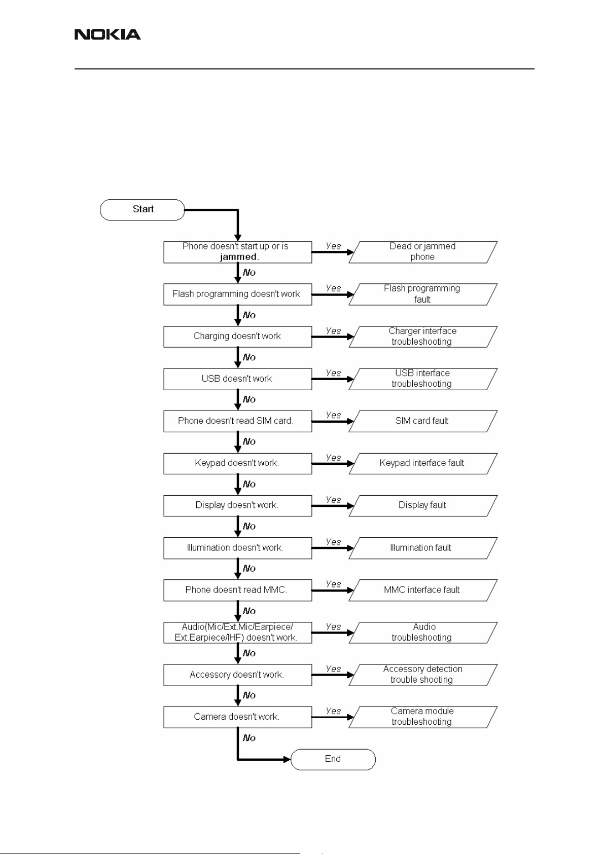
Baseband troubleshooting
This document is intended to be a guide for localising and repairing electrical faults in
the RH-51/52, RH-67/68 device. The fault repairing is divided into troubleshooting paths.
The following diagrams describe baseband troubleshooting.
Figure 1: Main troubleshooting diagram
Issue 3 09/2004 © 2004 Nokia Corporation. Page 7
Page 8
RH-51/52, RH-67/68 Company Confidential
6(a) - Baseband Troubleshooting Nokia Customer Care
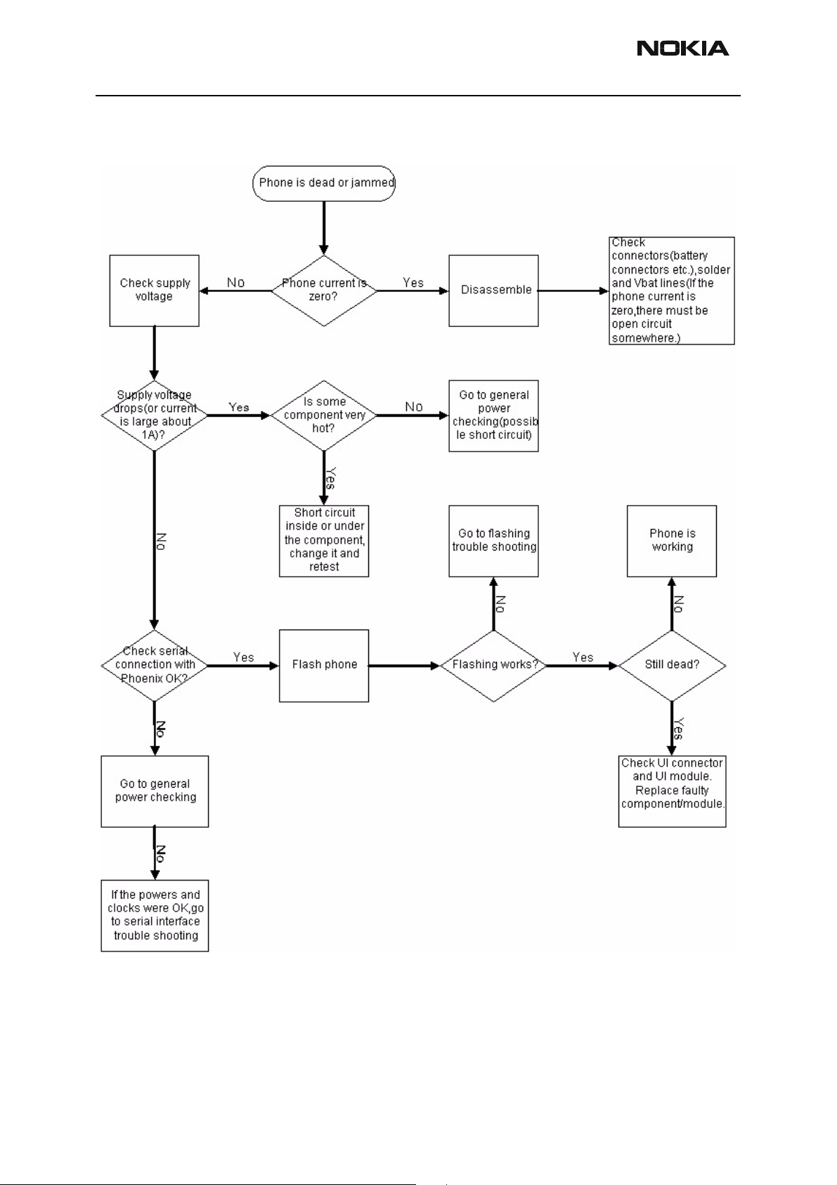
Dead or jammed phone
Figure 2: Phone is jammed or dead
Page 8 © 2004 Nokia Corporation. Issue 3 09/2004
Page 9
Company Confidential RH-51/52, RH-67/68
Nokia Customer Care 6(a) - Baseband Troubleshooting
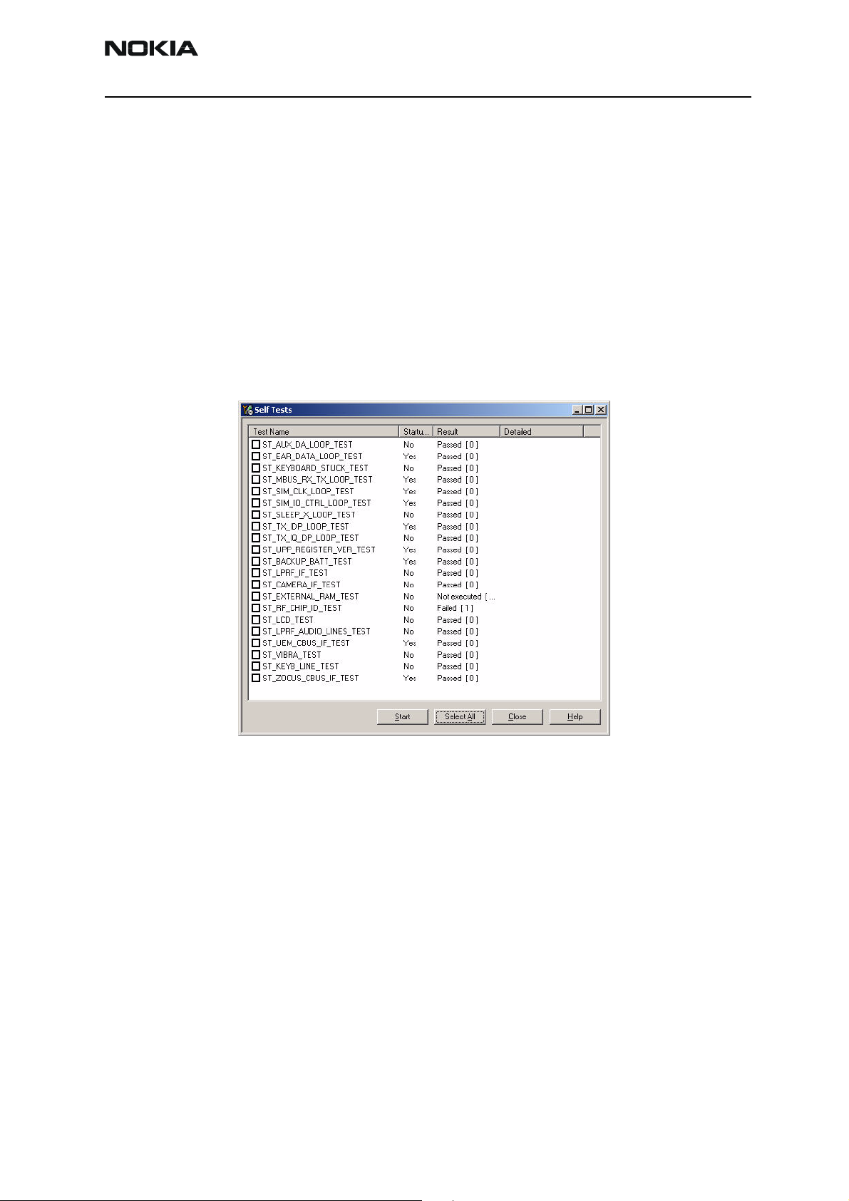
BB selftest tools
“Selftest failed. Contact service.” on display.
This fault means that the software is able to run and thus the watchdog of UEME can be
served. Selftest functions are executed when the phone is powered on, and if one or
more selftest functions fail, the message “Selftest failed. Contact Service.” is shown on
the display.
The MCU selftest case can be split into two categories: The ones that are executed during power up and the ones that are executed only with a PC connected. These tests and
the items included are as follows:
Figure 3: BB selftest items
Issue 3 09/2004 © 2004 Nokia Corporation. Page 9
Page 10
RH-51/52, RH-67/68 Company Confidential
6(a) - Baseband Troubleshooting Nokia Customer Care
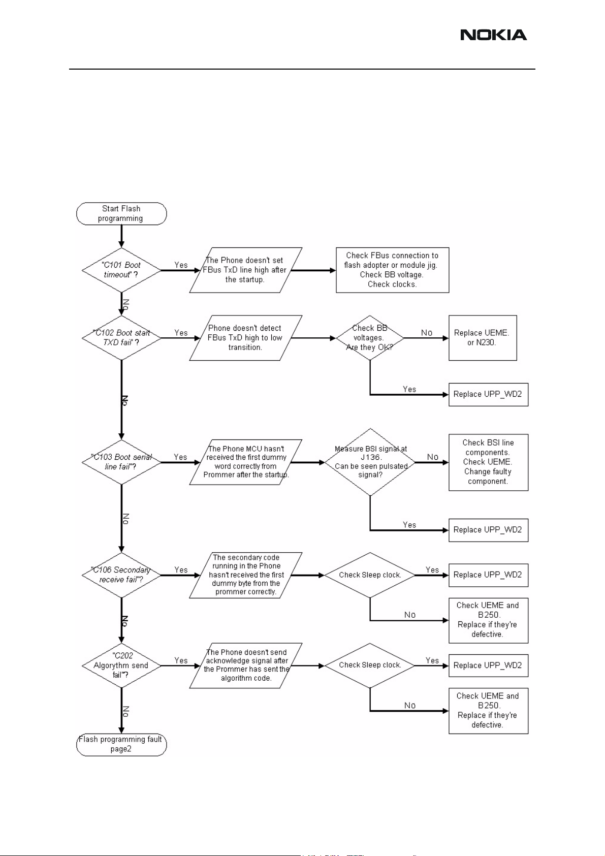
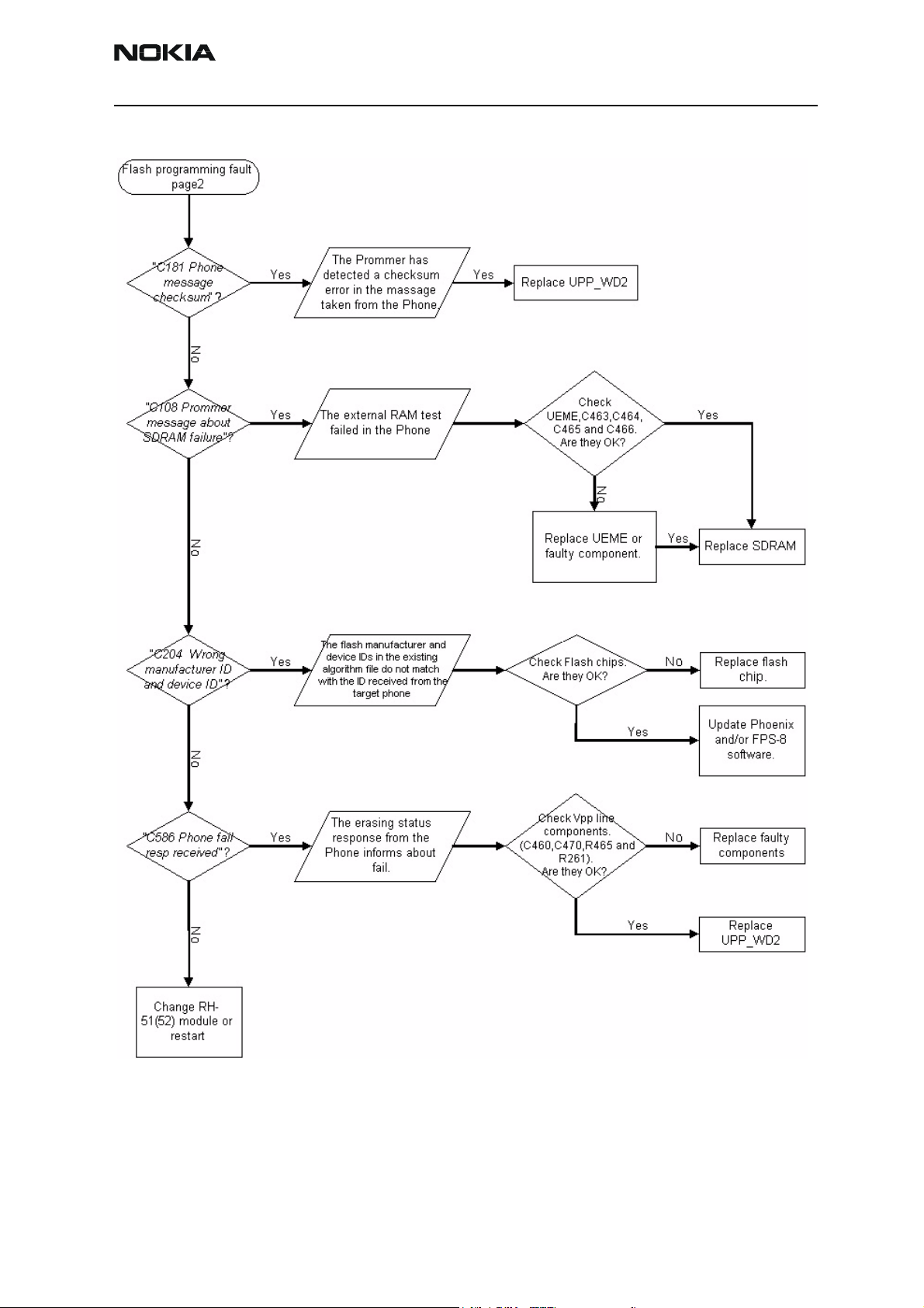
Flash programming fault
Following is the troubleshooting flow chart of flash programming.
“C101Boot timeoutl” written in the flow chart refers to the Phoenix error message that
is shown when there are problems on phone flash programming using FPS-8.
Figure 4: Flashing troubleshooting 1
Page 10 © 2004 Nokia Corporation. Issue 3 09/2004
Page 11
Company Confidential RH-51/52, RH-67/68
Nokia Customer Care 6(a) - Baseband Troubleshooting
Figure 5: Flashing troubleshooting 2
Issue 3 09/2004 © 2004 Nokia Corporation. Page 11
Page 12
RH-51/52, RH-67/68 Company Confidential
6(a) - Baseband Troubleshooting Nokia Customer Care
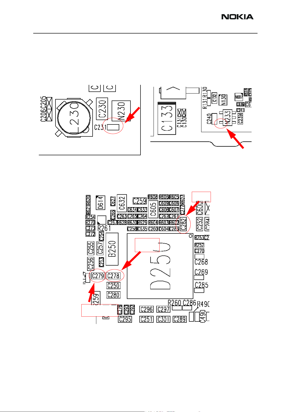
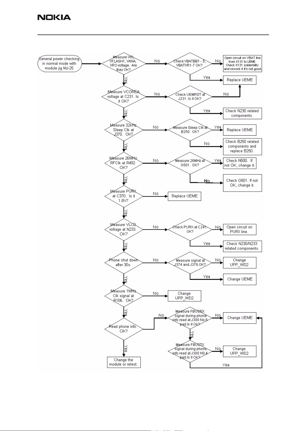
General power checking
Test points for regulators
VCOREA (LM2608/N230: 1.5V output)
Test point: C231 near by BT shield
UEME internal regulators
Test points: VIO 1.8V at C282
VANA 2.78V at C278
VFLASH1 2.78V at C279
VLCD (MAS9161/N233: 2.5V output)
Test point: N233 pin or C240 near.
VIO
VFLASH1
VANA
Page 12 © 2004 Nokia Corporation. Issue 3 09/2004
Page 13
Company Confidential RH-51/52, RH-67/68
Nokia Customer Care 6(a) - Baseband Troubleshooting
Figure 6: General power check
Issue 3 09/2004 © 2004 Nokia Corporation. Page 13
Page 14
RH-51/52, RH-67/68 Company Confidential
6(a) - Baseband Troubleshooting Nokia Customer Care
Baseband serial interface troubleshooting
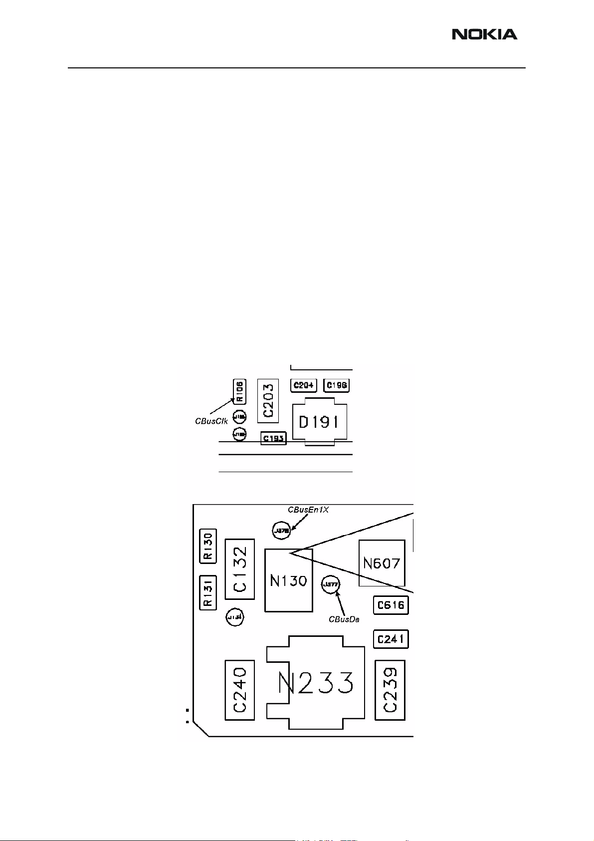
CBUS
CBUS is a three-wire serial interface between the main baseband components. The bus
consists of data, clock and bus_enable signals. In RH-51/52, RH-67/68 the bus is connected between UPP_WD2, UEME and ZOCUS. UPP_WD2 takes care of controlling the
traffic on the bus.
If the interface is faulty from the UPP_WD2’s end, the phone does not boot properly as
powering configurations do not work. Traffic on the bus can be monitored at the following test point and pins.
• CBusClk UPP_WD2 side of R106 pin
• CBusEN1X J378 Pad
• CBusDA J377 Pad
The pads and pin are shown below.
Figure 7: CBUS test points
Page 14 © 2004 Nokia Corporation. Issue 3 09/2004
Page 15
Company Confidential RH-51/52, RH-67/68
Nokia Customer Care 6(a) - Baseband Troubleshooting
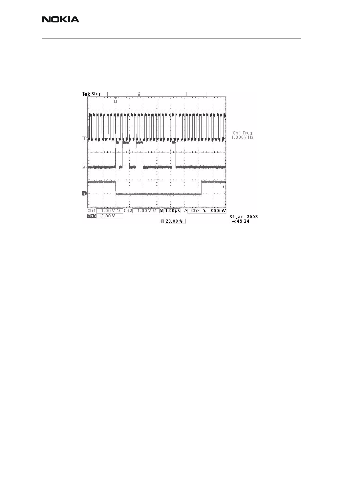
The CBUS traffic is shown in the figure below (read command to ZOCUS, LM3820, N130).
CBusCLk is connected to Ch1, CBusDa to CH2 and CBusEnx to Ch3.
Figure 8: CBUS waveform
FBUS
If you are able to get the phone to boot up and can reach Phoenix BB selftest it is possible to test the functionality of each component attached to CBus. Use:
• ST_UEM_CBUS_IF_TEST to test the UEME Cbus interface
• ST_ZOCUS_CBUS_IF_TEST to test the ZOCUS Cbus interface
If an error is found testing any of the above components you should replace or re-solder
the failed component.
FBUS is a two-wire RX and TX interface between UPP_WD2 and flash/test interface. The
bus goes through UEME, which adjusts the voltage levels to suit UPP_WD2. The interface
voltage level on the phone flash/test pad pattern is 2.7V and on the UPP_WD2 end it is
1.8V.
The functionality of this interface should not affect the device boot into NORMAL, LOCAL
or TEST modes. Phoenix tests can be performed through the MBUS interface in the case
of a failure in the FBUS interface. Flashing is not possible if there is a problem in the
FBUS interface.
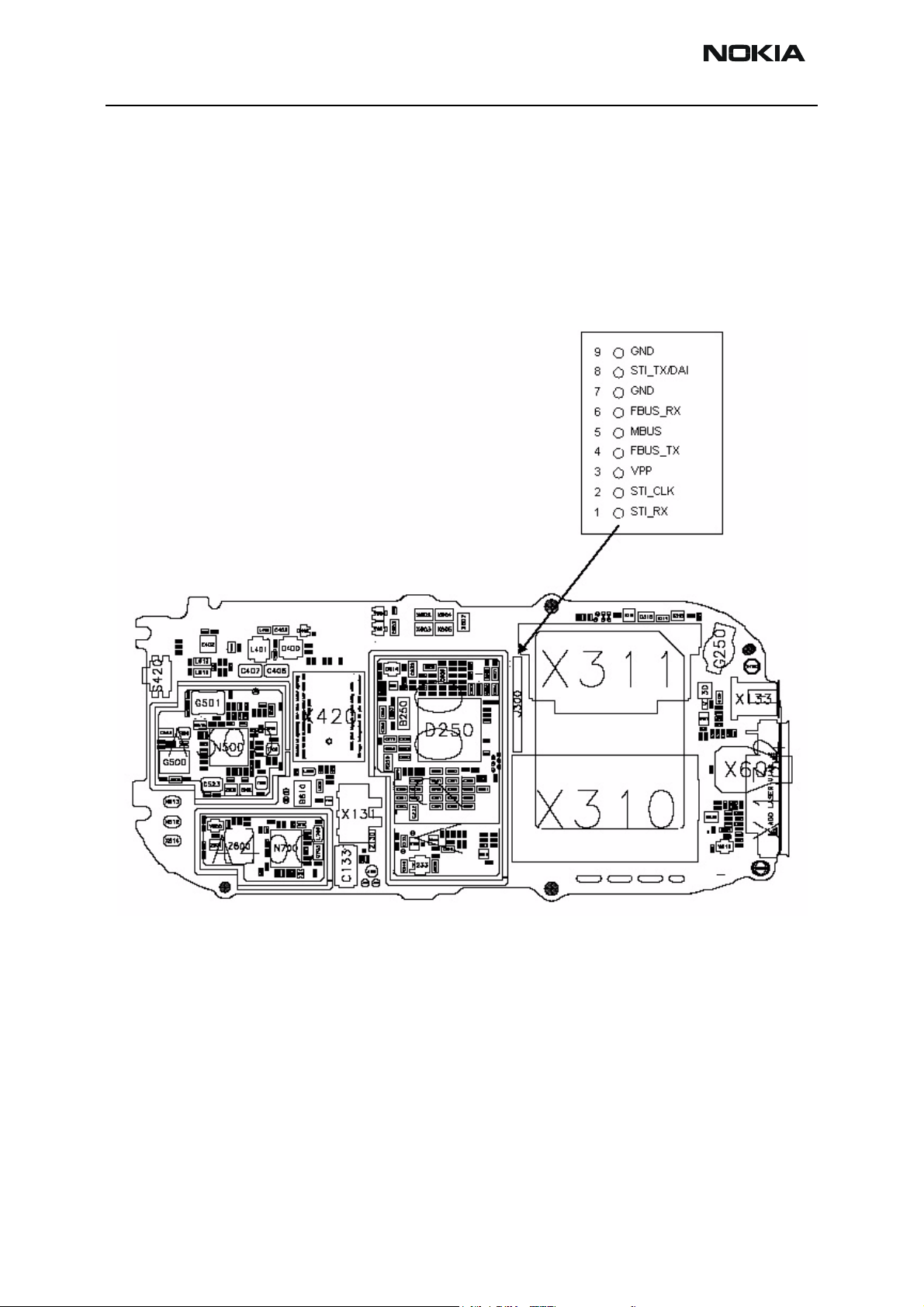
Fbus signals can be seen at flashing test pads and the pad layout is shown in the following figure.
MBUS
MBUS is a two-wire RX and TX interface between UPP_WD2 and UEME. From UEME the
interface continues to flash/test interface as one-wire interface. UEME adjusts the volt-
Issue 3 09/2004 © 2004 Nokia Corporation. Page 15
Page 16
RH-51/52, RH-67/68 Company Confidential
6(a) - Baseband Troubleshooting Nokia Customer Care
age levels.
The interface voltage level on the phone flash/test pad pattern is 2.78V and on the
UPP_WD2 end it is 1.8V. MBUS traffic between UPP_WD2 and UEME can be tested with
Phoenix (ST_MBUS_RX_TX_LOOP_TEST). Flashing is not possible if there is a problem in
MBUS. The MBUS signal can also be seen at flashing test pads and the pad layout is
shown in the following figure.
Figure 9: Flash interface layout (FBUS/MBUS test pads layout)
Page 16 © 2004 Nokia Corporation. Issue 3 09/2004
Page 17

Company Confidential RH-51/52, RH-67/68
Nokia Customer Care 6(a) - Baseband Troubleshooting
Charger interface troubleshooting
Figure 10: Not charging on display
Issue 3 09/2004 © 2004 Nokia Corporation. Page 17
Page 18

RH-51/52, RH-67/68 Company Confidential
6(a) - Baseband Troubleshooting Nokia Customer Care
Figure 11: Nothing happens when charging
Energy management calibration
EM calibrations should be carried out in JBV-1 docking station attached to DA-2 docking
station adapter.
Power to JBV-1 should be supplied from an external DC power supply.
JBV-1 input voltages: nominal + 12 VDC, maximum +16VDC
On the JBV-1, the A/D converter, BSI, BTEMP, battery voltage (VBAT), charger voltage
(VCHAR), charger current (ICHAR) and battery current (IBAT) are calibrated. For detailed
information and instructions, see energy management calibration instructions in the service manual.
Troubleshooting tips
ADC-offset over limits
Inspect the BSI line, connectors (hotbar and board to board connector) and components
in it (capacitor C272, ASIP R135, pull-up resistor R252). If these are OK, change UEME.
BSI gain over limits
Inspect the BSI line, connectors (hotbar and board to board connector) and components
in it (capacitor C272, ASIP R135, pull-up resistor R252). If these are OK, change UEME.
Vbatt offset and gain
Inspect Vbatt lines and components in it.
Page 18 © 2004 Nokia Corporation. Issue 3 09/2004
Page 19

Company Confidential RH-51/52, RH-67/68
Nokia Customer Care 6(a) - Baseband Troubleshooting
VCHAR over limits
Inspect components that are connected to VCHAR line: filtering capacitors C134, C135,
TVS V130, L130 and fuse F130. If those are OK, change UEM.
ICHAR over limits
Inspect components that are connected to VCHAR line: filtering capacitors C134, C135,
TVS V130, L130 and fuse F130. If those are OK, first change the current sense resistor
R259, if calibration is still not successful, change UEME.
Calibration can be checked using the ADC reading. Known voltages, currents and resistances are fed and read by the ADC reading, read values and known values can be compared.
ADC reading
Divided and scaled battery voltage, battery current, charger voltage, charger current and
BSI values can be read by this tool. Read values a few times before you can be sure that
results are accurate.
Figure 12: ADC reading view
Maximum tolerances:
Reading Check point Tolerance
Vbatt SCAL 4.2V ±25mV
Vchar 8.4V ±40mV
Ichar 500mA ±20mV
BSI 75k (BL-5C) ±1.3kohm
Btemp 273K (47k) ±5K
Issue 3 09/2004 © 2004 Nokia Corporation. Page 19
Page 20

RH-51/52, RH-67/68 Company Confidential
6(a) - Baseband Troubleshooting Nokia Customer Care
Backup battery
Symptom of backup battery fault is:
Real Time Clock loses the correct time during short battery removal.
The same symptom can also be seen when the backup battery is empty. About 30 minutes is needed to fully charge the backup battery in the device.
NOTE: The backup battery is charged only the same time with main battery charging, or when the device is in
LOCAL or TEST mode.
Always check the backup battery visually for any leakage or any other visual defect.
Check that the backup battery is correctly mounted in the device before closing the
cover.
Check with Phoenix that the backup battery is OK.
Measure the voltage of the backup battery.
• Normal operation when the voltage is > 2.0V.
• Fully charged when the voltage is about 3.2V.
Enable the backup battery charging (start to charge the main battery or boot the device
to LOCAL or TEST mode).
Measure the voltage of the backup battery during charging, it should arise if it is not 3.2
yet.
When the voltage is over 2.0V for sure, check the backup battery with Phoenix.
Page 20 © 2004 Nokia Corporation. Issue 3 09/2004
Page 21

Company Confidential RH-51/52, RH-67/68
Nokia Customer Care 6(a) - Baseband Troubleshooting
USB interface troubleshooting
Figure 13: USB interface troubleshooting
Issue 3 09/2004 © 2004 Nokia Corporation. Page 21
Page 22

RH-51/52, RH-67/68 Company Confidential
6(a) - Baseband Troubleshooting Nokia Customer Care
SIM card fault
The whole SIM interface is located in two chips; UPP_WD2 and UEME. UEME contains
the SIM interface logic level shifting. UPP_WD2 provides SIMClk through UEME to the
SIM. The SIM interface supports both 3V and 1.8V SIMs. There is an EMIF component (3
lines EMI filter) between the SIM card and the UEME which isn’t shown in the figure
below.
Figure 14: UPP_WD2 and UEME SIM connections
The SIM power up/down sequence is generated in the UEME. This means that the UEME
generates the RST signal to the SIM. The card detection is taken from the BSI signal,
which detects the removal of the battery. A comparator inside UEME monitors the BSI
signal. The threshold voltage is calculated from the battery size specifications.
First, the SW attempts to power up the SIM with 1.8V. If this does not succeed, power up
is repeated with VSIM switched to 3V.
The data communication between the card and the phone is asynchronous half duplex.
The clock supplied to the card is in GSM system 1.083MHz or 3.25MHz. The data boud
rate is SIM card clock frequency divided by 372 (by default), 64, 32, or 16.
Page 22 © 2004 Nokia Corporation. Issue 3 09/2004
Page 23

Company Confidential RH-51/52, RH-67/68
Nokia Customer Care 6(a) - Baseband Troubleshooting
Figure 15: SIM power up waveform
Figure 16: SIM answer to reset waveform
Issue 3 09/2004 © 2004 Nokia Corporation. Page 23
Page 24

RH-51/52, RH-67/68 Company Confidential
6(a) - Baseband Troubleshooting Nokia Customer Care
“Insert SIM Card” in device display although card is inserted
Figure 17: Insert SIM card troubleshooting
Page 24 © 2004 Nokia Corporation. Issue 3 09/2004
Page 25

Company Confidential RH-51/52, RH-67/68
Nokia Customer Care 6(a) - Baseband Troubleshooting
Keypad interface fault
Figure 18: Keypad troubleshooting 1
Issue 3 09/2004 © 2004 Nokia Corporation. Page 25
Page 26

RH-51/52, RH-67/68 Company Confidential
6(a) - Baseband Troubleshooting Nokia Customer Care
Figure 19: Keypad troubleshooting 2
Page 26 © 2004 Nokia Corporation. Issue 3 09/2004
Page 27

Company Confidential RH-51/52, RH-67/68
Nokia Customer Care 6(a) - Baseband Troubleshooting
Display fault
Figure 20: Display troubleshooting
Issue 3 09/2004 © 2004 Nokia Corporation. Page 27
Page 28

RH-51/52, RH-67/68 Company Confidential
6(a) - Baseband Troubleshooting Nokia Customer Care
Illumination fault (display/keyboard backlight)
Figure 21: Illumination troubleshooting 1
Page 28 © 2004 Nokia Corporation. Issue 3 09/2004
Page 29

Company Confidential RH-51/52, RH-67/68
Nokia Customer Care 6(a) - Baseband Troubleshooting
Figure 22: Illumination troubleshooting 2
Issue 3 09/2004 © 2004 Nokia Corporation. Page 29
Page 30

RH-51/52, RH-67/68 Company Confidential
6(a) - Baseband Troubleshooting Nokia Customer Care
MMC interface fault
Use with known working MMC to save the photo test. Target devices to replace are N310
Lester, R315 ASIP and X311 MMC connector. The MMC card itself might be broken, it
should be checked as well.
Figure 23: MMC troubleshooting
Page 30 © 2004 Nokia Corporation. Issue 3 09/2004
Page 31

Company Confidential RH-51/52, RH-67/68
Nokia Customer Care 6(a) - Baseband Troubleshooting
Audio troubleshooting
Internal microphone
Figure 24: Internal microphone troubleshooting
Internal
microphone
faulty
Check mic
module and PWB contacts.
Are the y ok?
yes
Set phone audio rout i ng f rom
MIC1 (hand portable) to known
working audio out put (i.e. EAR
(HP) or HF/HFCM (Ext)).
Ensure mic bias (MICB1) is on.
Is MIC bias
2.1V present at the
microphone?
yes
Clean contacts /
no
replace mic modul e
Check R604, R607,
C605 and other
passive components in
no
MIC bias path
Change
defect parts
no
Passive
components ok? (correct
value/ no short circuit to
GND)
Change
defect parts
Change UEME
yes
no
Are the
audio signals to
UEME ok?
yes
Does
audio work in
a call?
yes
End
Check audio path
through C606, C607
no
no
and associated
components
Change
UPP_WD2
Passive
components ok?
(correct value/ no short
circuit to GND)
Change UEME
yes
Issue 3 09/2004 © 2004 Nokia Corporation. Page 31
Page 32

RH-51/52, RH-67/68 Company Confidential
6(a) - Baseband Troubleshooting Nokia Customer Care
External microphone
Figure 25: External microphone troubleshooting
External
microphone
faulty
Connect headset HDB-4
to system connector
Check system
connector X132.
Is it ok?
yes
Set phone audio routing from
MIC2 (Ext. XMIC) to known
working audio outpu t (i.e. EAR
(HP) of HF/HFCM (Ext)). Ensure
MIC bias (MIC2) is on.
Is MIC bias
2.1V present at L616
or at the system
connetor?
yes
Are the
audio signals to
UEME ok?
yes
Clean contacts /
no
no
no
replace X132
Check R628 and other
passive components in
MIC bias path.
Check audio path through C633,
C634, R629, R630 and associat ed
passives. Also check t he Hookint line
through R635. Check for shorts to
GND and open inseries components.
Change
defect parts
no
Passive
components ok? (correct
value/ no short circuit to
GND)
Change
defect parts
no
Passive
components ok? (correct
value/ no short circuit to
GND)
Change UEME
yes
Change UEME
yes
Does
audio work in
a call?
yes
End
no
Change
UPP_WD2
Page 32 © 2004 Nokia Corporation. Issue 3 09/2004
Page 33

Company Confidential RH-51/52, RH-67/68
Nokia Customer Care 6(a) - Baseband Troubleshooting
Internal earpiece
Check that holes are not coated.
Figure 26: Internal earpiece troubleshooting
Internal
earpiece faulty
Check earpiece
and PWB contacts.
Are they ok?
yes
Set phone audio routing f rom a
known working MIC input to
EAR N/P. Ensure the correct
MIC bias is on.
Is the EAR
DC bias voltage seen on
the EAR P/N paths or at
the earpiece pads?
yes
Are the
audio signals from
UEME to earpiece
ok?
yes
Clean contacts /
replace earpiece &
no
Check audio path from UEME
to the earpiece pads. Check
no
no
for shorts to GND or between
Check audio path from UEME
to the earpiece pads. Check
for shorts to GND o r between
the lines. Change passives
gasket
the lines. Change passives
where necessary.
where necessary.
Change
defect parts
no
Passive
components ok? (correct
value/ no short circuit to
GND)
Change
defect parts
no
Passive
components ok?
(correct value/ no short
circuit to GND)
Change UEME
yes
Change UEME
yes
Does
audio work in
a call?
yes
End
no
Change
UPP_WD2
Issue 3 09/2004 © 2004 Nokia Corporation. Page 33
Page 34

RH-51/52, RH-67/68 Company Confidential
6(a) - Baseband Troubleshooting Nokia Customer Care
External earpiece
Figure 27: External earpiece troubleshooting
External
earpiece faulty
Connect headset HDB-4
to system connector
mechanical appearance and
solderings of system connector.
Check
Is it ok?
yes
Set phone audio routing from a
known working MIC input to
HF/HFCM. Ensure that correct
MIC bias is on.
Is the
HF DC bias voltage
seen on the HF & HFCM
lines at X132?
yes
Replace system
no
no
connector X132
Check audio path through
L618, L619, R634 and
associated passives. Check for
shorts to GND and open
inseries components.
Change
defect parts
no
Passive
components ok? (correct
value/ no short circuit to
GND)
Change
defect parts
Change UEME
yes
no
Are the
audio signals from
UEME to the X132
ok?
yes
Does
audio work in
a call?
yes
End
Check audio path through
L618, L619, R634 and
associated passives. Check for
no
no
shorts to GND and open
inseries components.
Change
UPP_WD2
Passive
components ok? (correct
value/ no short circuit to
GND)
Change UEME
yes
Page 34 © 2004 Nokia Corporation. Issue 3 09/2004
Page 35

Company Confidential RH-51/52, RH-67/68
Nokia Customer Care 6(a) - Baseband Troubleshooting
IHF
Figure 28: IHF troubleshooting
IHF
troubleshooting
Check IHF speaker
contacts and PWB pads. Check that
speaker impedance is 8 ohm .
Is it ok?
yes
Set phone audio routing from a
known working MIC input to
PAOUTP & PAOUTN. Ensure
that correct MIC bias is on.
yes
Is the DC bias voltage
(1/2 VBAT) measurable at
the IHF speaker pads?
yes
no
replace IHF speaker /
Is VBAT provided t o N607 ?
no
Check voltage at J380.
DC bias (1/2 VBAT)
measurable on the inp ut pa th
of N607? (check at R611
Check audio path f r om N607 t o
IHF pads. Check passives around
N607. Check for shorts to GND
or between the lines. Change
passives where necessary
Clean contacts /
IHF connector
(check at C616)
yes
Is it 1.8V ?
yes
Is the
& R612)
yes
VBAT line failed
around N607. Swap
no
engine board.
Change UPP_WD2
no
Are C611, C612, R611 and
no no
R612 ok?
yes
Change UEME
Replace defect
components
Is the
Connect
headset HDB-4 to X132,
activate audio routing from
ext. MIC to IHF. Check audio
signal at IHF pads wit h
oscilloscope.
Is it ok?
DC bias (1/2 VBAT)
no
measurable on the IHF
speaker pad s?
Check passives
around N607, change
parts if n ece ssary
no
yes
Change N607
Check
audio signal at IHF pads with
oscilloscope. Is it ok?
no
Change N607
yes
yes
Does audio work in a call?
no
Change UPP_WD2
yes
End
Issue 3 09/2004 © 2004 Nokia Corporation. Page 35
Page 36

RH-51/52, RH-67/68 Company Confidential
6(a) - Baseband Troubleshooting Nokia Customer Care
Accessory detection troubleshooting
Figure 29: Accessory detection troubleshooting
Page 36 © 2004 Nokia Corporation. Issue 3 09/2004
Page 37

Company Confidential RH-51/52, RH-67/68
Nokia Customer Care 6(a) - Baseband Troubleshooting
Issue 3 09/2004 © 2004 Nokia Corporation. Page 37
Page 38

RH-51/52, RH-67/68 Company Confidential
6(a) - Baseband Troubleshooting Nokia Customer Care
Camera module troubleshooting
A fault associated to camera operation can be roughly categorized to three subgroups:
43 Camera is not functional at all, no image can be obtained.
44 Images can be taken but there is nothing recognizable in them.
45 Images can be taken and they are recognizable but for some reason the quality of
images is seriously degraded.
Image quality is very hard to measure quantitatively, and even comparative measurements are difficult (comparing two images) if the difference is small. Especially, if the
user is not satisfied with his/her device’s image quality, and tells e.g. that the images are
not sharp, it is very difficult to test the device and get an exact figure which then would
tell if the device is OK or not.
Most often, subjective evaluation has to be used for finding out if a certain property of
the camera is acceptable or not. Some training and a correctly operating reference
device maybe needed in order to detect what actually is wrong, or is there anything
wrong at all. It is easy for the user to take bad looking images in bad conditions; thus the
camera operation has to be checked always in constant conditions (lighting, temperature) or by using a second, known to be good device as a reference. Experience significantly helps in analysing image quality.
Terms
Dynamic range: The camera’s ability to capture details in dark and bright areas of the
scene simultaneously.
Exposure time: The camera modules use silicon sensor to collect light and for forming
an image. The imaging process roughly corresponds to traditional film photography, in
which exposure time means the time during which the film is exposed to the light coming through optics. Increasing the time will allow for more light hitting the film and thus
results in brighter image. The operation principle is exactly the same with silicon sensor,
but the shutter functionality is handled electronically, i.e. there is no mechanical moving
parts like in film cameras.
Flicker: A phenomenon, which is caused by pulsating in scene lighting, typically appearing as wide horizontal stripes in image.
Noise: Variation of response between pixels with the same level of input illumination.
See e.g. Figure “Noisy image taken in +70deg” for an example of a noisy image.
Page 38 © 2004 Nokia Corporation. Issue 3 09/2004
Page 39

Company Confidential RH-51/52, RH-67/68
Nokia Customer Care 6(a) - Baseband Troubleshooting
Image taking condition effect on image quality
This chapter lists some of the factors, which may cause poor image quality if not taken
into account, and thus result in complaints from customers.
Several issues affect the image quality and will need to be taken into account when
shooting pictures; the listed items are normal to camera operation.
Distance to target
The lens in the module is specified to operate satisfactorily from 40 cm to infinite distance of scene objects. In practice, the operation is such that close objects may be
noticed to get more blurred when distance to them is shortened from 40 cm. Lack of
sharpness will be first visible in full resolution (1Mpixel) images. If observing just the
viewfinder, even very close objects may seem to appear sharp.
Sharpness of picture edges
The lens performance degrades in image edges, and generally the image is sharpest in
the center part. Particularly this applies to distant objects (> 1 meter).
See the following figure.
Figure 30: Sharpness of picture is worse in edges than in center
Geometrical distortion
The camera lens will cause some amount of so called barrel distortion in images. In practice, this appears as bending of straight objects in edges of the image.
See the figure below. Note geometrical barrel distortion in background for example (wall
in the background).
Issue 3 09/2004 © 2004 Nokia Corporation. Page 39
Page 40

RH-51/52, RH-67/68 Company Confidential
6(a) - Baseband Troubleshooting Nokia Customer Care
Amount of light available
In dim conditions the camera runs out of sensitivity. Exposure time is long (especially in
night mode) and the risk of getting shaken images grows. Image noise level grows. The
maximum exposure time in night mode is approximately ¼ seconds, so images need to
be taken with extreme care when the amount of light reflected from the target is low.
Figure 31: Shaking hands caused blurring of this image. Note geometrical barrel disortion in background.
Movement in bright light
If pictures of moving objects are taken or if the device is used in a moving car, object
’skewing’ or ‘tilting’ will occur. This phenomenon is fundamental to most CMOS cameras,
and can not be helped. Movement of camera or object will usually cause blurring in
inside or dim lighting conditions due to long exposure time.
Figure 32: Near objects in image get skewed when shooting from a moving car
Temperature
High temperatures inside the mobile phone will cause more noise to appear in images,
e.g. in +70oC the noise level may be very high, and it further grows if the conditions are
dim. This is also normal to camera operation. (See the following figure.)
Page 40 © 2004 Nokia Corporation. Issue 3 09/2004
Page 41

Company Confidential RH-51/52, RH-67/68
Nokia Customer Care 6(a) - Baseband Troubleshooting
Figure 33: Noisy image taken in +70deg
Display
If the display contrast is set too dark, the image quality degrades quite much: the images
may be very dark, naturally depending on the setting. This flaw is easily cured by setting
the display contrast to correct value.
Basic rules of photography, especially shooting against light
Electronic image sensors typically have a much lower dynamic range than films. In practice, this means that when taking a picture inside e.g. having a window behind the
object, will produce poor results.
Figure 34: Image which has been taken “against the light”. The actual object (a squirrel) can’t be seen well
Flicker
In some rare occasions a very bright fluorescent light may cause flicker to be seen in the
viewfinder image.
Issue 3 09/2004 © 2004 Nokia Corporation. Page 41
Page 42

RH-51/52, RH-67/68 Company Confidential
6(a) - Baseband Troubleshooting Nokia Customer Care
Figure 35: Flicker in image of white uniform object illuminated by strong fluorescent light
Bright light outside of image view
Especially sun causes clearly visible ‘halo’ effects and poor contrast in images. This happens due to unwanted reflections inside camera optics.
Figure 36: A lens reflection effect caused by sun shining above the scene
Figure 37: A good quality picture taken indoors
Note: The camera module as a component is not a repairable part, i.e. components in the module may not be
changed. Cleaning dust from the front face is the only allowable operation.
Page 42 © 2004 Nokia Corporation. Issue 3 09/2004
Page 43

Company Confidential RH-51/52, RH-67/68
Nokia Customer Care 6(a) - Baseband Troubleshooting
Image quality analysis
Possible faults in image quality
When checking for possible errors in camera functionality, knowing what error is suspected will significantly help the testing by narrowing down the amount of test cases.
The following types of image quality problems may be expected to appear (in order of
appearance probability):
• Dust (black spots)
• Lack of sharpness
• Bit errors
In addition, there are many other kinds of possibilities for getting bad image quality, but
those are ruled out from the scope of this document since probability of their appearance is going to be minimized by production testing.
Testing for dust
For detecting this kind of problems, take an image of uniform white surface and analyse
it in full resolution; search carefully – finding these defects is not always easy. See the
following figure.
Effects of dust in the optical path are an example of image containing easily detectable
dust problems.
Black spots in image are caused by dirt particles trapped into the optical system: clearly
visible and sharp edged black dots in image are typically dust particles on the image sensor.
These spots are searched for in the manufacturing phase, but it is possible that the lens
holder cavity contains a particle, which may move onto the image sensor active surface,
e.g. when the phone is dropped. Thus, it is also possible that the problem will disappear
before the phone is brought to service. The camera should be replaced if it has been in
some phase verified that the problem has been present.
If dust particles are located on infrared filter surface on either side, they are much harder
to locate because they will be out of focus, and appear in image as large, greyish and
fading-edge ‘blobs’. Sometimes they will be very hard to find, and thus the user probably
will not notice them at all since they do no harm. But it is possible that a larger particle
disturbs the user, causing need for service.
Issue 3 09/2004 © 2004 Nokia Corporation. Page 43
Page 44

RH-51/52, RH-67/68 Company Confidential
6(a) - Baseband Troubleshooting Nokia Customer Care
Figure 38: Effects of dust in optical path
If large dust particles get trapped on top of the lens surface in the cavity between camera window and lens, they will cause image blurring and poor contrast (see also item
‘sharpness’). The seal between the window and lens should prevent any particles from
getting into the cavity after manufacturing phase.
If dust particles are found on the sensor or are suspected to be inside the camera module, this is classified as a manufacturing error of the module and thus the camera should
be replaced. The particles inside the cavity between window and lens have most probably
been trapped there in the assembly phase in the factory. It is of course also possible that
the user has disassembled the device and caused the problem. However, in most cases it
should be possible to remove the particle(s) by using compressed air. Never wipe the lens
surface before trying compressed air; the possibility of damaging the lens is substantial.
Always check the image sharpness after removing dust.
Testing for sharpness
If pictures taken with a device are claimed to be blurry, there are four possible sources
for the claim:
• The user has tried to take pictures in too dark conditions and images are blurred due
to handshake or movement. No need to replace camera module.
• There is dirt between the back window and camera lens.
The back window is defective. Window should be changed.
• Back window is visibly scratched, broken or dirty.
• Camera lens is misfocused.
Quantitative analysis of sharpness is very difficult to conduct in other than optics laboratory environment. Thus subjective analysis should be used.
If no visible defects (items 2-4) can be found, a couple of test images should be taken
and checked. Generally, a well illuminated typical indoor office scene, such as the one in
Figure “A good quality picture taken indoors”, can be used as a target.
Page 44 © 2004 Nokia Corporation. Issue 3 09/2004
Page 45

Company Confidential RH-51/52, RH-67/68
Nokia Customer Care 6(a) - Baseband Troubleshooting
The main considerations are:
Amount of light: 300 – 600 lux (bright office lighting) is sufficient.
The scene should contain e.g. small objects for checking sharpness and distance to them
should be in order of 1 – 2 meters
If possible, compare the image to another image of the same scene, taken by different
device.
The taken images should be analysed on PC screen at 100% scaling simultaneously with
reference image. Pay attention to the computer display settings; at least 65000 colors
(16bit) have to be used. 256 (8-bit) color setting is not sufficient, and true color (24bit,
16 million colors) or 32 bit (full color) setting is recommended.
If there appears to be a clearly noticeable difference between the reference image and
the test images, the module might have misfocused lens. In this case, the module should
be changed. Always re-check the resolution after changing the camera. If a different
module produces the same result, the fault is probably in the camera window. Check the
window by looking through it when replacing the module.
Bit errors
Bit errors are defects in image caused by data transmission error between the camera
and phone baseband. This type of error is expected to be rare since usually missing bits
will cause a hardware failure message. Bit errors can be typically seen in images taken of
any object, and they should be most visible in full Mega pixel resolution images.
Viewfinder images may not contain the errors at all due to lower bit rate used in this
mode.
A good practice is to use uniform white test target.
The errors will be clearly visible as colorful sharp dots or lines in camera Mega pixel
images.
Issue 3 09/2004 © 2004 Nokia Corporation. Page 45
Page 46

RH-51/52, RH-67/68 Company Confidential
6(a) - Baseband Troubleshooting Nokia Customer Care
Camera hardware failure troubleshooting flow
If camera related hardware is faulty, follow the troubleshooting sequence below.
Figure 39: Camera HW troubleshooting
Page 46 © 2004 Nokia Corporation. Issue 3 09/2004
Page 47

Company Confidential RH-51/52, RH-67/68
Nokia Customer Care 6(a) - Baseband Troubleshooting
Figure 40: Hardware failure troubleshooting
Issue 3 09/2004 © 2004 Nokia Corporation. Page 47
Page 48

RH-51/52, RH-67/68 Company Confidential
6(a) - Baseband Troubleshooting Nokia Customer Care
Bad image quality
Figure 41: Bad image quality troubleshooting
Page 48 © 2004 Nokia Corporation. Issue 3 09/2004
Page 49

Company Confidential RH-51/52, RH-67/68
Nokia Customer Care 6(a) - Baseband Troubleshooting
Baseband tuning operation
Energy managment calibration is always required when the following components are
changed.
• charging related components
• ZOCUS (N130) and related components
• UEME (D250) and related components
• BSI related components
Energy management calibration
EM (Energy Management) calibration is performed to calibrate the setting (gain and offset) of AD converters in several channels (i.e. battery voltage, BSI, charger voltage,
charger current).
This is to get accurate conversion result of AD converter.
HW setup
“JBV-1 service concept” is needed.
An external power supply is needed.
The RH-51/52, RH-67/68 phone must be connected to JBV-1 (docking station) with DA18 (docking station adapter).
• Connect SCB-3 (DC-DC cable) between JBV-1 and charger connector of phone for
charger channel calibration.
• Supply 11-16V DC from an external power supply to JBV-1 to power up phone.
Phoenix SW setup
• Start Phoenix service software.
• Select FBUS connection.
• Choose Main -> Choose product-> RH-51, -52, -67 or -68.
• Choose Tuning -> Energy Management Calibration.
Issue 3 09/2004 © 2004 Nokia Corporation. Page 49
Page 50

RH-51/52, RH-67/68 Company Confidential
6(a) - Baseband Troubleshooting Nokia Customer Care
Figure 42: EM calibration window
Calibration procedure with JBV-1
Select “Read from phone” to show the current values in the phone memory, and then
check that the communication with the phone works.
Select “JBV-1 used” check box.
Select the item(s) you try to calibrate.
Note: ADC has to be calibrated before other item(s). If the ADC value is correct or you calibrate ADC and
other items at the same time, that’s OK.
Select “Calibrate”.
Calibration is carried out automatically regarding the calibration item(s) that you
selected.
The candidate of the new calibration values is shown in the “calculated” field. If the new
calibration values seem to be reasonable (please refer to the calibration value limit
table), select “Write to PM” to store the new calibration value in the phone permanent
memory.
Select “Read from phone” and confirm that the new calibration values are stored in the
phone memory correctly. If not, please try to store by selecting “Write to PM” again.
Page 50 © 2004 Nokia Corporation. Issue 3 09/2004
Page 51

Company Confidential RH-51/52, RH-67/68
Nokia Customer Care 6(a) - Baseband Troubleshooting
Close the Energy Management Calibration widow.
Parameter Min. Max.
ADC Gain 26500 28500
ADC Offset -50 50
BSI Gain 950 1100
VBAT Gain 10000 11000
VBAT Offset 2300 2900
VCHAR Gain 58000 62000
ICHAR Gain 3750 4650
ICHAR Offset 0 150
IBAT Gain 50 160
Issue 3 09/2004 © 2004 Nokia Corporation. Page 51
Page 52

RH-51/52, RH-67/68 Company Confidential
6(a) - Baseband Troubleshooting Nokia Customer Care
This page has been deliberately left blank
Page 52 © 2004 Nokia Corporation. Issue 3 09/2004
 Loading...