

Page 1

Nokia Customer Care
4 — Service Tools and Service
Concepts
Issue 1 Company Confidential Page 4–1
Copyright © 2004 Nokia. All Rights Reserved.
Page 2

RM-1
Nokia Customer Care Service Tools and Service Concepts
(This page left intentionally blank.)
Page 4–2 Company Confidential Issue 1
Copyright © 2004 Nokia. All Rights Reserved.
Page 3

RM-1
Service Tools and Service Concepts Nokia Customer Care
Table of Contents
Service tools.....................................................................................................................................................................................4–5
AD-23FS.........................................................................................................................................................................................4–5
CA-35S...........................................................................................................................................................................................4–5
CU-4................................................................................................................................................................................................4–5
DKU-2.............................................................................................................................................................................................4–6
FPS-10...........................................................................................................................................................................................4–6
JBT-9..............................................................................................................................................................................................4–6
MJ-26.............................................................................................................................................................................................4–7
MJS-76...........................................................................................................................................................................................4–7
PCS-1..............................................................................................................................................................................................4–7
PKD-1.............................................................................................................................................................................................4–8
RF shield box...............................................................................................................................................................................4–8
RJ-48..............................................................................................................................................................................................4–8
SA-64.............................................................................................................................................................................................4–8
SES-3..............................................................................................................................................................................................4–8
SS-15..............................................................................................................................................................................................4–8
SS-46..............................................................................................................................................................................................4–9
SX-4................................................................................................................................................................................................4–9
XCS-4..............................................................................................................................................................................................4–9
XRF-1..............................................................................................................................................................................................4–9
Service concepts...........................................................................................................................................................................4–10
Flash concept with FPS-10..................................................................................................................................................4–10
MJ-26 module jig concept...................................................................................................................................................4–11
POS (Point of Sale) flash concept......................................................................................................................................4–12
Service concept for RF testing and BB tuning...............................................................................................................4–13
CU-4 flash concept with FPS-10.........................................................................................................................................4–14
RF testing concept with RF coupler..................................................................................................................................4–15
List of Figures
Figure 35 Basic flash concept with FPS-10...........................................................................................................................4–10
Figure 36 MJ-26 module jig service concept........................................................................................................................4–11
Figure 37 POS flash concept......................................................................................................................................................4–12
Figure 38 Service concept for RF testing and BB tuning..................................................................................................4–13
Figure 39 CU-4 flash concept with FPS-10.............................................................................................................................4–14
Figure 40 RF testing concept with RF coupler.....................................................................................................................4–15
Issue 1 Company Confidential Page 4–3
Copyright © 2004 Nokia. All Rights Reserved.
Page 4

RM-1
Nokia Customer Care Service Tools and Service Concepts
(This page left intentionally blank.)
Page 4–4 Company Confidential Issue 1
Copyright © 2004 Nokia. All Rights Reserved.
Page 5
RM-1
Service Tools and Service Concepts Nokia Customer Care
Service tools
List of Service Tools
The table below gives a short overview of service tools that can be used for testing, error analysis and repair
of product , refer to various concepts.
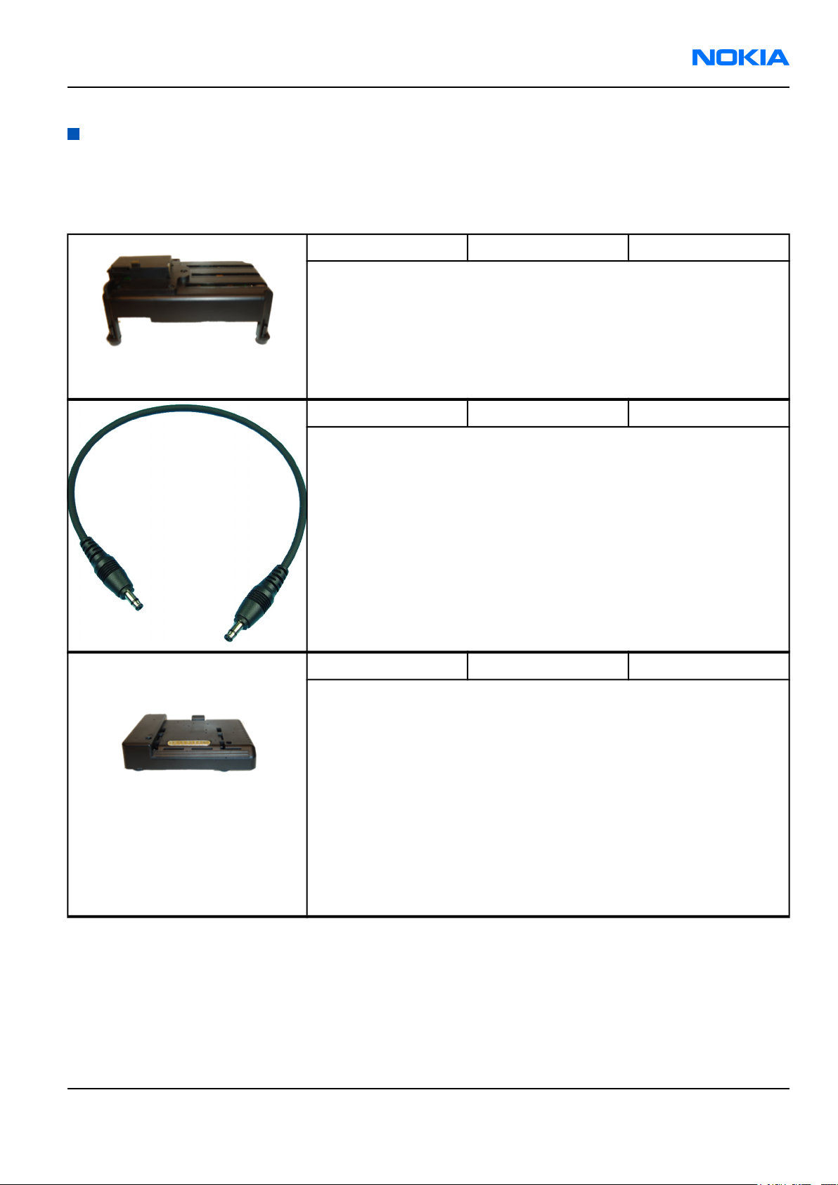
AD-23FS Flash adapter 0780391
AD-23FS has the following features:
• Provides galvanic connection to terminal test pads
• Provides standardized interface towards Control Unit
• Provides RF connection using galvanic connector or coupler
Multiplexing between USB and FBUS media, controlled by Vusb
CA-35S power cable 0730327
The power cable CA-35S is used to power up the interface adapter SS-46.
CU-4 Control unit 0770831
CU-4 is a general service tool used with a module jig and a flash adapter.
CU-4 requires an external 12 V power supply.
The unit has the following features:
• software controlled via USB
• EM calibration function
• Forwards FBUS/Flashbus traffic to/from terminal
• Forwards USB traffic to/from terminal
• software controlled BSI values
• regulated VBATT voltage
• 2 x USB2.0 connector (Hub)
• FBUS and USB connections supported
Issue 1 Company Confidential Page 4–5
Copyright © 2004 Nokia. All Rights Reserved.
Page 6

RM-1
Nokia Customer Care Service Tools and Service Concepts
DKU-2 USB connectivity cable 0730238
USB to Pop-PortTM connector cable.
FPS-10 Flash prommer 0080321
FPS-10 interfaces with:
• PC
• Control unit
• Flash adapter
• Smart card
FPS-10 flash prommer features:
• Provides flash functionality for BB5 terminals
• Smart Card reader for SX-2 or SX-4
• Forwards USB traffic through it
• Provides USB to FBUS/Flashbus conversion
• Provides LAN to FBUS/Flashbus and USB conversion
• Vusb output switchable by PC command
FPS-10 sales package includes:
• FPS-10 prommer (0770503)
• Power Supply with 5 country specific cords (0675525)
• USB cable (0730322)
JBT-9 Bluetooth test and
interface box (sales
pack)
The JBT-9 testbox is a generic device to perform Bluetooth bit error rate
testing and doing cordless FBUS connection via Bluetooth. An ACP-8x
charger is needed for BER testing and AXS-4 cable in case of cordless
testing interface usage.
• JBT-9 testbox (0770336)
• Installation and warranty information (9360613)
Page 4–6 Company Confidential Issue 1
Copyright © 2004 Nokia. All Rights Reserved.
0081490
Page 7

RM-1
Service Tools and Service Concepts Nokia Customer Care
MJ-26 Module jig 0770833
MJ-26 is meant for component level troubleshooting.
The jig includes an RF interface for GSM, WCDMA and Bluetooth. In
addition, it has the following features:
• Provides mechanical interface with Engine module
• Provides galvanic connection to all needed test pads in module
• Multiplexing between USB and FBUS media, controlled by Vusb
• UI test interface
• MMC interface
• Duplicated SIM connector
• Audio components: IHF, MIC, earpiece
• Connector for control unit
•
Access for Pop-PortTM system connector
Note: In the picture CU-4 is connected to MJ-26 . CU-4 is not part
of the MJ-26 sales package and has to be ordered separately.
MJS-76 LGA rework jig 0770417
This tool is used in LGA type component reworking purposes in central
service centers.
Parts list:
•
Part
number
1 Frame SME5S910 1
2 Cylindrical
3 Cylindrical
4 Type label 9380601 1
PCS-1 Power cable 0730012
The PCS-1 power cable (DC) is used with a docking station or a module
jig to supply a controlled operating voltage.
Part name Material
code
640b003 1
pin 3 x 12
640B012 1
pin 3 x 12
Drawing
number
Qty
Issue 1 Company Confidential Page 4–7
Copyright © 2004 Nokia. All Rights Reserved.
Page 8

RM-1
Nokia Customer Care Service Tools and Service Concepts
PKD-1 SW security device 0750018
SW security device is a piece of hardware enabling the use of the service
software when connected to the parallel (LPT) port of the PC.
Without the device, it is not possible to use the service software.
Printer or any such device can be connected to the PC through the device
if needed.
Caution: Do not connect the PKD-1 to the serial port.
RF shield box RF shield box N/A
Because the WCDMA network disturbs the RX side testing of the WCDMA
phone and the Tx signal of the WCDMA phone can severely disturb the
WCDMA network, a shield box is needed in all testing, tuning and fault
finding which requires WCDMA RF signal.
The shield box is not an active device, it contains only passive filtering
components for RF attenuation.
RJ-48 Rework jig 0780365
RJ-48 is a soldering jig used for soldering and as a rework jig for the
engine module.
SA-64 RF coupler 0780409
SA-64 is a coupler for WCDMA / GSM RF testing. It is used together with
AD-23FS flash adapter.
SES-3 Stencil 4350383
SES-3 stencil is used with MJS-76 / 0770417 and it supports the PA
component.
SES-3 is made for reworking purposes used in central service level.
SS-15 Camera removal tool 0770755
The camera removal tool SS-15 is used to remove/attach the camera
module from/to the socket on the phone PWB.
Page 4–8 Company Confidential Issue 1
Copyright © 2004 Nokia. All Rights Reserved.
Page 9

RM-1
Service Tools and Service Concepts Nokia Customer Care
SS-46 Interface adapter 0780510
SS-46 acts as an interface adapter between AD-23FS adapter and FPS-10.
SX-4 Smart card 0780392
SX-4 is a BB5 security device used to protect critical features in tuning
and testing.
SX-4 is also needed together with FPS-10 when DCT-4 phones are flashed.
XCS-4 Modular cable 0730178
XCS-4 is a shielded (one specially shielded conductor) modular cable for
flashing and service purposes.
XRF-1 RF cable 0730085
The RF cable is used to connect, for example, a module repair jig to the
RF measurement equipment.
SMA to N-Connector ca. 610mm.
Attenuation for:
• GSM850/900: 0.3+-0.1 dB
• GSM1800/1900: 0.5+-0.1 dB
• WLAN: 0.6+-0.1dB
Issue 1 Company Confidential Page 4–9
Copyright © 2004 Nokia. All Rights Reserved.
Page 10

RM-1
Nokia Customer Care Service Tools and Service Concepts
Service concepts
Flash concept with FPS-10
Figure 35 Basic flash concept with FPS-10
Item Description Type Code
1 AD-23FS Flash adapter 0780391
2 SS-46 Interface adapter 0780510
3 CA-35S Power cable 0730327
4 XCS-4 Modular cable 0730178
5 Standard USB cable
6 FPS-10 Flash prommer box 0080321
7 Standard USB cable
8 PKD-1 SW security device 0750018
Page 4–10 Company Confidential Issue 1
Copyright © 2004 Nokia. All Rights Reserved.
Page 11

RM-1
Service Tools and Service Concepts Nokia Customer Care
MJ-26 module jig concept
Figure 36 MJ-26 module jig service concept
Item Type Description Code
1 MJ-26 Module jig 0770833
2 CU-4 Control unit 0770831
3 FPS-10 Flash prommer box 0080321
4 SX-4 Smart card 0780392
5 XCS-4 Modular cable 0730178
6 PCS-1 DC power cable 0730012
7 Standard USB cable
8 Standard USB cable
9 GPIB control cable
10 XRF-1 RF antenna cable 0730085
11 PKD-1 SW security device 0750018
12 RF shield box N/A
Note: Item 12 not shown in the picture.
Issue 1 Company Confidential Page 4–11
Copyright © 2004 Nokia. All Rights Reserved.
Page 12

RM-1
Nokia Customer Care Service Tools and Service Concepts
POS (Point of Sale) flash concept
Figure 37 POS flash concept
Item Type Description Code
1 DKU-2 USB connectivity cable 0730238
2 PKD-1 SW security device 0750018
Page 4–12 Company Confidential Issue 1
Copyright © 2004 Nokia. All Rights Reserved.
Page 13

RM-1
Service Tools and Service Concepts Nokia Customer Care
Service concept for RF testing and BB tuning
Figure 38 Service concept for RF testing and BB tuning
Item Description Type Code
1 MJ-26 Module jig 0770833
2 CU-4 Control unit 0770831
3 Standard USB cable
4 PCS-1 DC power cable 0730012
5 Standard USB cable +
smart card reader
6 SX-4 Smart card 0780392
7 XRF-1 RF cable 0730085
8 GPIB control cable
9 PKD-1 SW security device 0750018
10 RF shield box N/A
Note: Item 10 not shown in the picture.
Issue 1 Company Confidential Page 4–13
Copyright © 2004 Nokia. All Rights Reserved.
Page 14

RM-1
Nokia Customer Care Service Tools and Service Concepts
CU-4 flash concept with FPS-10
Figure 39 CU-4 flash concept with FPS-10
Item Description Type Code
1 AD-23FS Flash adapter 0780391
2 CU-4 Control unit 0770831
3 PCS-1 Power cable 0730012
4 XCS-4 Modular cable 0730178
5 FPS-10 Flash prommer box 0080321
6 Standard USB cable
7 Standard USB cable
8 PKD-1 SW security device 0750018
Page 4–14 Company Confidential Issue 1
Copyright © 2004 Nokia. All Rights Reserved.
Page 15

RM-1
Service Tools and Service Concepts Nokia Customer Care
RF testing concept with RF coupler
Figure 40 RF testing concept with RF coupler
Item Type Description Code
1 AD-23FS Flash adapter 0780391
2 CU-4 Control unit 0770831
3 SA-64 RF coupler 0780409
4 PCS-1 Power cable 0730012
5 Standard USB cable
6 Standard USB cable +
smart card reader
7 SX-4 Smart card 0780392
8 GPIB control cable
9 XRF-1 RF antenna cable 0730085
10 PKD-1 SW security device 0750018
11 RF shield box N/A
Note: Item 11 not shown in the picture.
Issue 1 Company Confidential Page 4–15
Copyright © 2004 Nokia. All Rights Reserved.
Page 16

RM-1
Nokia Customer Care Service Tools and Service Concepts
(This page left intentionally blank.)
Page 4–16 Company Confidential Issue 1
Copyright © 2004 Nokia. All Rights Reserved.
 Loading...