

Page 1

Nokia Customer Care
NHL-12 Series Transceivers
3 - Service Sof tware
Instructions
Issue 3 05/2005 COMPANY CONFIDENTIAL
Copyright © 2005 Nokia. All Rights Reserved.
Page 2

NHL-12 Company Confidential
3 - Service Software Instructions Nokia Customer Care
[This page intentionally blank]
2 © 2005 Nokia Corporation. Issue 3 05/2005
Page 3

NHL-12
3 - Service Software Instructions Nokia Customer Care
Table of Contents
Page No
Quick Guide for Phoenix Service SW Installation............................................ 5
Phoenix installation steps in brief....................................................................... 5
Phoenix Service SW............................................................................................6
Before installation .............................................................................................. 6
Startup ............................................................................................................... 6
Installing dongle driver and checking version .................................................... 8
Installing Phoenix............................................................................................... 9
Updating Phoenix............................................................................................. 11
Uninstalling Phoenix ........................................................................................ 12
Data Package for Phoenix (Product Specific) ................................................15
Before installation ............................................................................................ 15
Installing Phoenix data package (product specific).......................................... 15
Uninstalling data package................................................................................ 18
Managing connections..................................................................................... 19
Updating Flash Support Files for FPS-8* and FLS-4S*.................................. 23
Before installation ............................................................................................ 23
Installing the flash support files........................................................................ 23
Updating FPS-8* flash prommer SW ............................................................... 26
Activating and Deactivating FPS-8.................................................................. 29
Activating FPS-8.............................................................................................. 29
Deactivating FPS-8.......................................................................................... 31
JBV-1 Docking Station Software ..................................................................... 32
Before installation ............................................................................................ 32
Installing software needed for the JBV-1 SW update ...................................... 32
Updating JBV-1 docking station software ........................................................ 36
Receiver Tuning: Quick Guide for Tuning with Phoenix............................... 37
General remarks.............................................................................................. 37
Service tool concept for RF tuning operations................................................. 38
Autotuning........................................................................................................ 39
Set loss ..........................................................................................................40
Environment ................................................................................................... 40
Protection .......................................................................................................41
Receiver manual tuning................................................................................... 42
Rx Channel Select Filter Calibration ..............................................................42
Rx Calibration ................................................................................................42
Rx Band Filter Response Compensation .......................................................46
Rx Am Suppression .......................................................................................51
Transmitter manual tuning............................................................................... 55
Issue 3 05/2005 COMPANY CONFIDENTIAL 3
Copyright © 2005 Nokia. All Rights Reserved.
Page 4

NHL-12
Nokia Customer Care 3 - Service Software Instructions
Tx Power Level Tuning ..................................................................................55
Tx I/Q Tuning .................................................................................................63
Service Tool Concept for Baseband Tuning Operations............................... 69
Baseband Tuning Operations.......................................................................... 71
Energy management calibration ....................................................................71
Phoenix Self Tests ............................................................................................ 73
Flashing Setup Instructions............................................................................. 75
POS (Point of Sale) flash concept ................................................................... 75
JBV-1 flash concept......................................................................................... 76
Module jig concept........................................................................................... 78
Service concept for calibrations....................................................................... 79
Connecting SA-5 and XRS-11 ....................................................................... 80
Parallel flash concept....................................................................................... 82
Bluetooth testing with JBT-9............................................................................ 83
Flash fail situations .......................................................................................... 84
0xC602 ...........................................................................................................84
0xC686 ...........................................................................................................85
0xC684 ...........................................................................................................86
0xC101 or 0xC102 or 0xC103 ....................................................................... 86
Reprogramming NHL-12...................................................................................89
Connecting cables ........................................................................................... 89
Backing up settings.......................................................................................... 89
Updating software............................................................................................ 90
Formatting user area........................................................................................ 91
Restoring settings............................................................................................ 91
Restoring settings from the MMC card ..........................................................91
Restoring settings with Phoenix ..................................................................... 91
4 COMPANY CONFIDENTIAL Issue 3 05/2005
Copyright © 2005 Nokia. All Rights Reserved.
Page 5

NHL-12
3 - Service Software Instructions Nokia Customer Care
1. §Quick Guide for Phoenix Service SW Installation
■ Phoenix installation steps in brief
These are the basic steps to install the Phoenix:
• Install the Phoenix service SW.
• Install the data package for Phoenix (product specific data and flash update package).
• Manage connection settings (depends on the tools you are using).
• Update FPS-8 SW (if you use FPS-8).
• Activate FPS-8.
• Update JBV-1 docking station SW (only when needed).
The flash update files are delivered with then Phoenix data package so unless you want to use
certain version of this package, separate installation package is not needed. If you want to use
it, it should be installed after connection management, before FPS-8 update.
Please refer to Service Manual and Technical Bulletins for more information concerning phone
model specific service tools and equipment setup.
Issue 3 05/2004 COMPANY CONFIDENTIAL 5
Copyright © 2005 Nokia. All Rights Reserved.
Page 6
NHL-12
Nokia Customer Care 3 - Service Software Instructions
2. Phoenix Service SW
■ Before installation
Administrator rights may be required to be able to install Phoenix depending on the operating
system.
• Check that a dongle is attached to the parallel port of your computer.
• Download the latest available version of the installation package (for example,
phoenix_service_sw_a7_2004_9_2_3.exe) to your computer (e.g. C:\TEMP).
• Close all other programs.
• Run the application file (e.g. phoenix_service_sw_a7_2004_9_2_3.exe) and
follow instructions on the screen.
• If the dongle driver is installed or updated, you need to reboot your PC before the
installation can continue.
• If uninstalling or rebooting is needed at any point, you will be prompted by the Install Shield program.
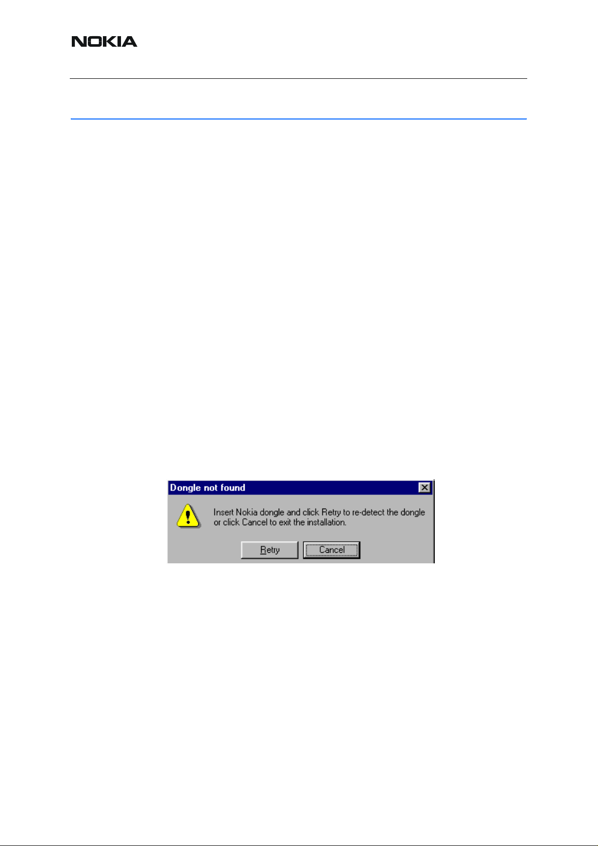
If at any point during installation you get this message:
“Dongle is not found and installation cannot continue”.
Possible reasons may be defective or too old PKD-1 dongle (five digit serial number dongle
when used with FPS-8 prommer) or that the FLS-4S POS flash dongle is defective or power to
it is not supplied by external charger.
Check the COM /parallel ports used first! After correcting the problem Installation can be restarted.
■ Startup
1. To start installation, run the application file (e.g.
phoenix_service_sw_a7_2004_9_2_3.exe).
6 COMPANY CONFIDENTIAL Issue 3 05/2004
Copyright © 2005 Nokia. All Rights Reserved.
Page 7

NHL-12
3 - Service Software Instructions Nokia Customer Care
2. To extract the files needed for installation, click “Next”.
If the setup files are already extracted (left in the file system from previous installation), the following dialog box appears.
3. To overwrite the existing setup files, click "Yes to All".
Issue 3 05/2004 COMPANY CONFIDENTIAL 7
Copyright © 2005 Nokia. All Rights Reserved.
Page 8

NHL-12
Nokia Customer Care 3 - Service Software Instructions
■ Installing dongle driver and checking version
If there is no previously installed dongle driver, a new installation takes place.
If the dongle driver is installed and it is older than the latest supported version, the latest version
will be installed when you click “Yes”. The latest version is always included in the latest Phoenix
installation package.
PC needs to be rebooted before installation can continue. To reboot the PC, click "Yes".
Setup is restarted automatically after reboot.
8 COMPANY CONFIDENTIAL Issue 3 05/2004
Copyright © 2005 Nokia. All Rights Reserved.
Page 9
NHL-12
3 - Service Software Instructions Nokia Customer Care
■ Installing Phoenix
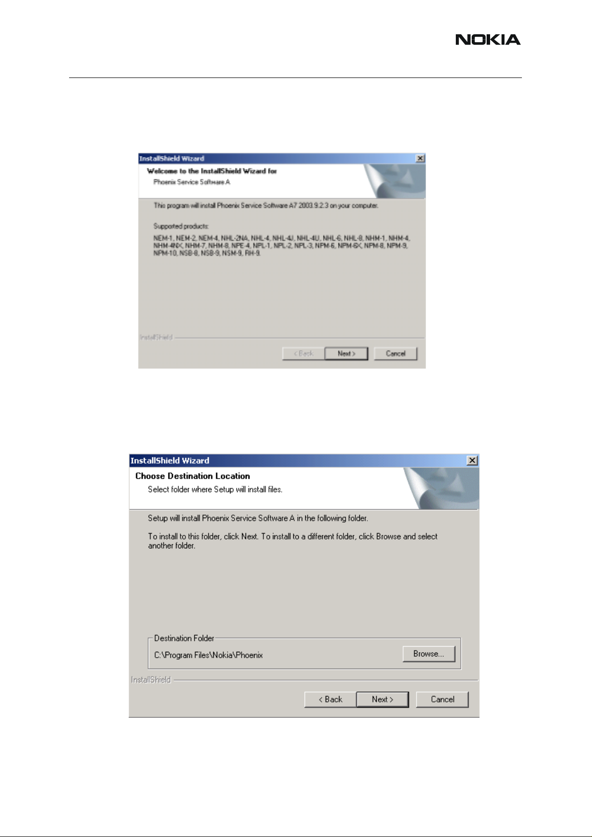
After dongle driver installation / update (if needed) installation continues from this step.
1. In the Welcome dialog box, click "Next" to continue.
2. Choose the destination folder. It is recommended to use the default folder:
C:\ProgramFiles\Nokia\Phoenix.
To choose another location, click “Browse” (not recommended).
3. To continue, click “Next”.
Setup copies the components, please wait.
Issue 3 05/2004 COMPANY CONFIDENTIAL 9
Copyright © 2005 Nokia. All Rights Reserved.
Page 10

NHL-12
Nokia Customer Care 3 - Service Software Instructions
The progress of the setup is shown. Please wait.
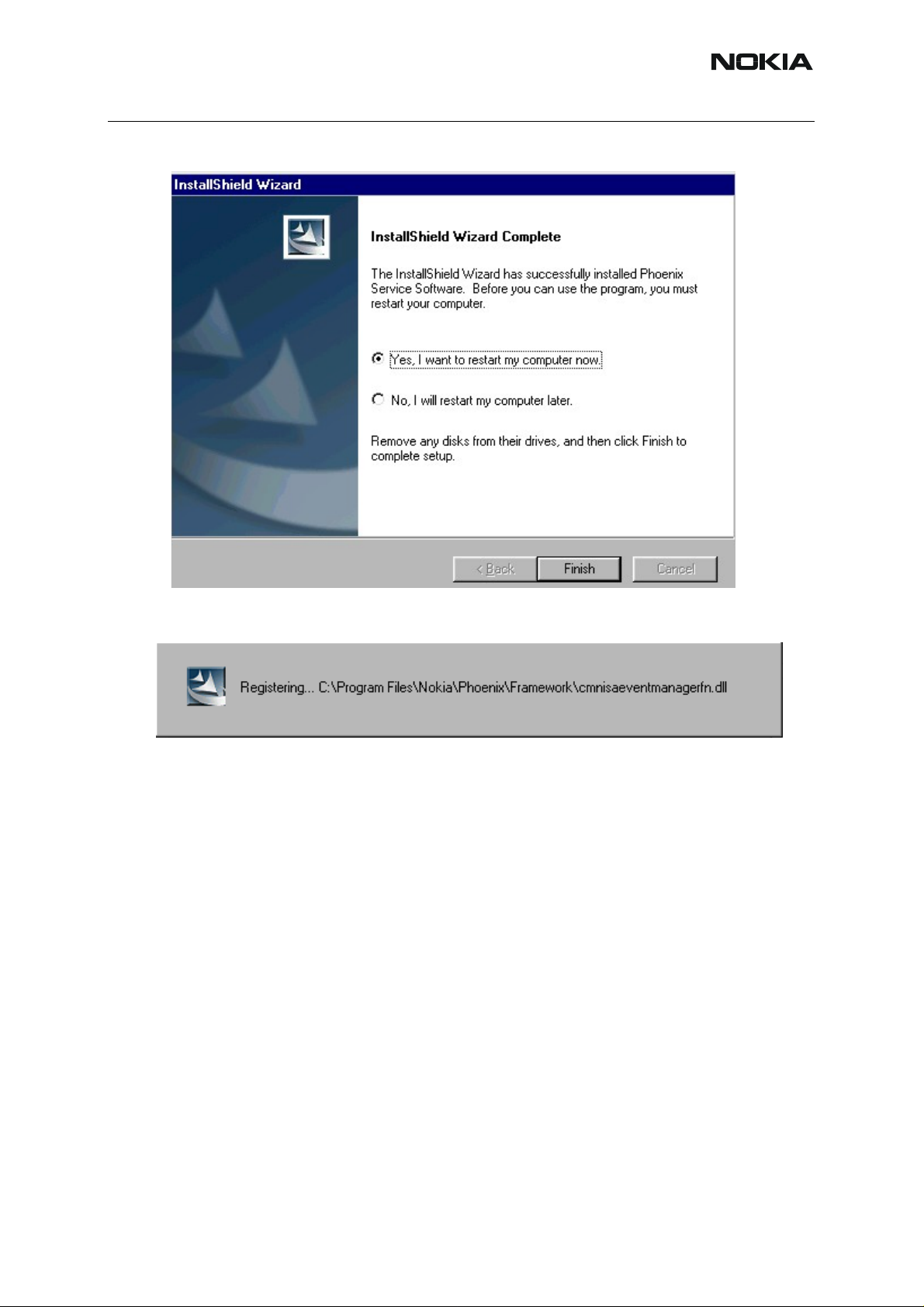
If restarting of your computer is needed, the Install Shield Wizard notifies you
about it.
4. To reboot the PC immediately, select "Yes...". To reboot the PC manually,
check "No...".
Note that Phoenix does not work, if components are not registered.
10 COMPANY CONFIDENTIAL Issue 3 05/2004
Copyright © 2005 Nokia. All Rights Reserved.
Page 11
NHL-12
3 - Service Software Instructions Nokia Customer Care
5. To continue, click "Finish".
After the reboot, components are registered and Phoenix is ready for use.
If reboot is not needed, components are registered after copying them.
6. If restarting of your computer is not needed, Click "Finish" to exit the setup.
Phoenix is now ready for use.
Now the installation of Phoenix Service SW is ready and it can be used after:
• Installing phone model specific phone data package for Phoenix.
• Configuring the connections.
• Updating the flash update package files used with FPS-8* and FLS-4S* tools.
■ Updating Phoenix
If you already have the Phoenix service SW installed on your computer, sooner or later there
will be need for an update.
Please note that very often the Phoenix service SW and the phone specific data package for
Phoenix come in pairs, meaning that certain version of Phoenix can only b e used with certain
version of data package. Always use the latest available versions of both. Instructions can be
found in phone model specific Technical Bulletins.
To update Phoenix, you need to take exactly the same steps as when installing it for the first
time:
Issue 3 05/2004 COMPANY CONFIDENTIAL 11
Copyright © 2005 Nokia. All Rights Reserved.
Page 12

NHL-12
Nokia Customer Care 3 - Service Software Instructions
1. Download the installation package to your computer hard disk.
2. Close all other programs.
3. Run the application file (e.g. phoenix_service_sw_a7_2004_9_2_3.exe).
Dongle driver version is checked and if need be, updated.
After reboot installation starts automatically.
Newer version of Phoenix is installed.
When you update the Phoenix from old to new version (e.g. update from 2004_9_2_3 to
2004_9_2_5), the update will take place automatically without uninstallation.
If you try update the Phoenix with the same version that you already have, you are asked if you
want to uninstall the version of Phoenix you have on your PC.
To uninstall Phoenix, click “OK”.
If you do not want to uninstall, click “Cancel”.
If you try to install an older version (e.g. downgrade from 2004_9_2_3 to 2004_9_1_2) installation will be interrupted.
Note! Always follow the instructions on the screen.
■ Uninstalling Phoenix
To uninstall Phoenix manually:
1. From the Windows Control Panel, choose Add / Remove Programs.
2. Choose “Phoenix Service Software” and click "Add/Remove".
12 COMPANY CONFIDENTIAL Issue 3 05/2004
Copyright © 2005 Nokia. All Rights Reserved.
Page 13

NHL-12
3 - Service Software Instructions Nokia Customer Care
3. To uninstall, click “OK”
The progress of the uninstallation is shown.
Issue 3 05/2004 COMPANY CONFIDENTIAL 13
Copyright © 2005 Nokia. All Rights Reserved.
Page 14
NHL-12
Nokia Customer Care 3 - Service Software Instructions
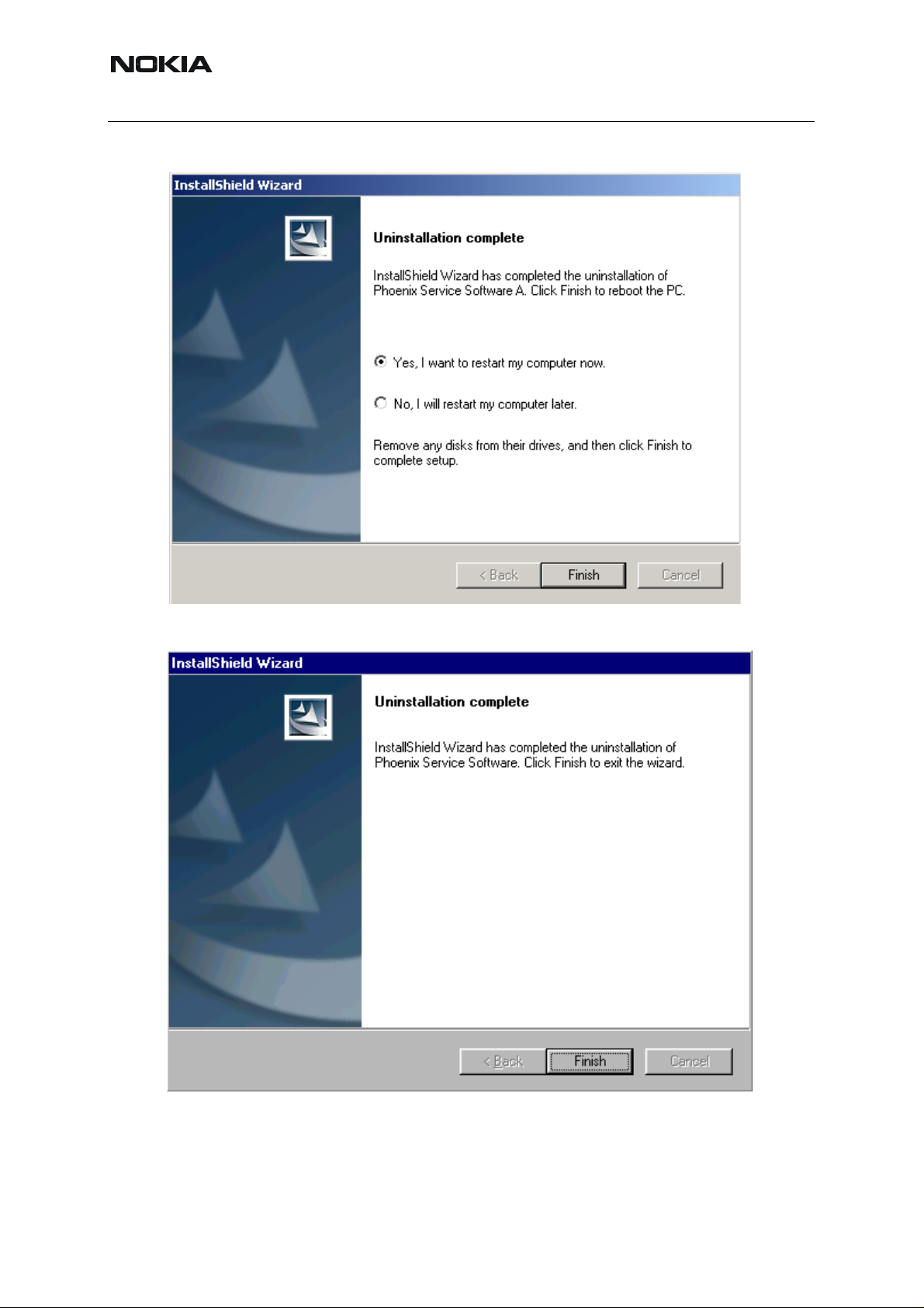
You may have to reboot the PC after uninstallation.
If restarting is not needed, the following dialog box appears:
Note! If you have different product packages installed, components are uninstalled only if they
are not included in other product packages.
14 COMPANY CONFIDENTIAL Issue 3 05/2004
Copyright © 2005 Nokia. All Rights Reserved.
Page 15

NHL-12
3 - Service Software Instructions Nokia Customer Care
3. Data Package for Phoenix (Product Specific)
■ Before installation
Product data package contains all product specific data to make the Phoenix service software
and tools usable with a certain phone model.
It also includes the latest version of flash update package for FLS-4S* and FPS-8*
• Check that the dongle is attached to the parallel port of your computer.
• Install Phoenix service SW.
• Download the installation package (e.g. nhl-12_dp_v1.0_sw3.02.exe) to your
computer (e.g. C:\TEMP).
• Close all other programs.
• Run the application file (e.g.nhl-12_dp_v1.0_sw3.02.exe) and follow instructions
on the screen.
If you already have the Phoenix service SW installed on your computer, sooner or later there
will be need to update it when new versions are released.
Please note that very often the Phoenix service SW and the phone specific data package for
Phoenix come in pairs, meaning that certain version of Phoenix can only be used with certain
version of a data package. Always use the latest available versions of both. Instructions can be
found in phone model specific Technical Bulletins.
■ Installing Phoenix dat a package (product specific)
To start installation:
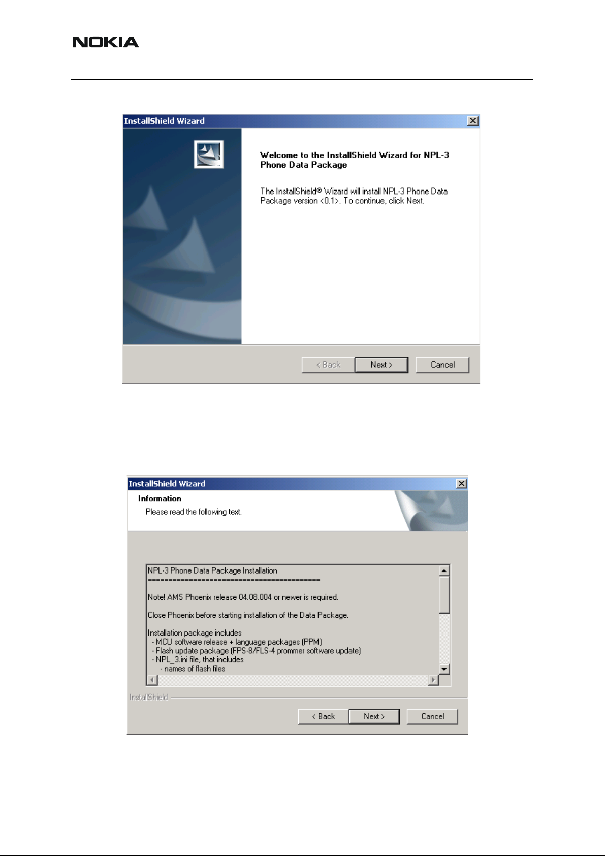
1. Run the application file (e.g. nhl-12_dp_v1.0_sw3.02.exe).
2. To extract the files needed for installation, click “Next”. Please wait.
Issue 3 05/2004 COMPANY CONFIDENTIAL 15
Copyright © 2005 Nokia. All Rights Reserved.
Page 16
NHL-12
Nokia Customer Care 3 - Service Software Instructions
3. To continue, click “Next”.
In the following view you can see the contents of the data package. Read the text
carefully.
There should be information about the Phoenix version needed with this data
package.
4. Click “Next”.
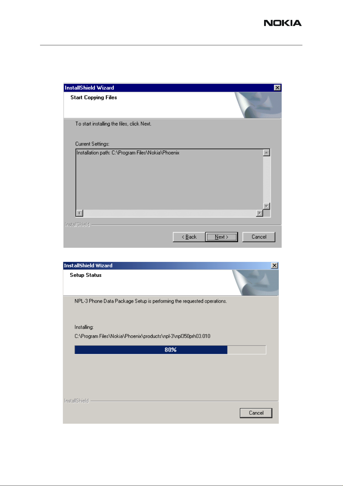
5. Confirm location and click “Next” to continue.
16 COMPANY CONFIDENTIAL Issue 3 05/2004
Copyright © 2005 Nokia. All Rights Reserved.
Page 17
NHL-12
3 - Service Software Instructions Nokia Customer Care
Install Shield checks where the Phoenix application is installed and the directory
is shown.
6. To continue, click “Next”.
Phone model specific files are installed. Please wait.
Issue 3 05/2004 COMPANY CONFIDENTIAL 17
Copyright © 2005 Nokia. All Rights Reserved.
Page 18

NHL-12
Nokia Customer Care 3 - Service Software Instructions
7. To complete installation, click “Finish”.
You now have all phone model specific files installed in your Phoenix service SW.
■ Uninstalling data package
To uninstall the data package manually:
1. From the Windows Control Panel, choose Add / Remove Programs/ “NHL-12
Phone Data Package”.
If you try to install the same version of Phoenix data package that you already have,
you are asked if you want to uninstall it.
2. To uninstall, click “OK”.
If you do not want to uninstall, click “Cancel”.
Older versions of data packages need not be uninstalled.
18 COMPANY CONFIDENTIAL Issue 3 05/2004
Copyright © 2005 Nokia. All Rights Reserved.
Page 19

NHL-12
3 - Service Software Instructions Nokia Customer Care
3. Once the previously installed data package is uninstalled, click “Finish”.
4. To continue installation from the beginning, run the application file (e.g. nhl-
12_dp_v1.0_sw3.02.exe).
■ Managing connections
To manage connections:
1. Start Phoenix service SW and login.
Issue 3 05/2004 COMPANY CONFIDENTIAL 19
Copyright © 2005 Nokia. All Rights Reserved.
Page 20

NHL-12
Nokia Customer Care 3 - Service Software Instructions
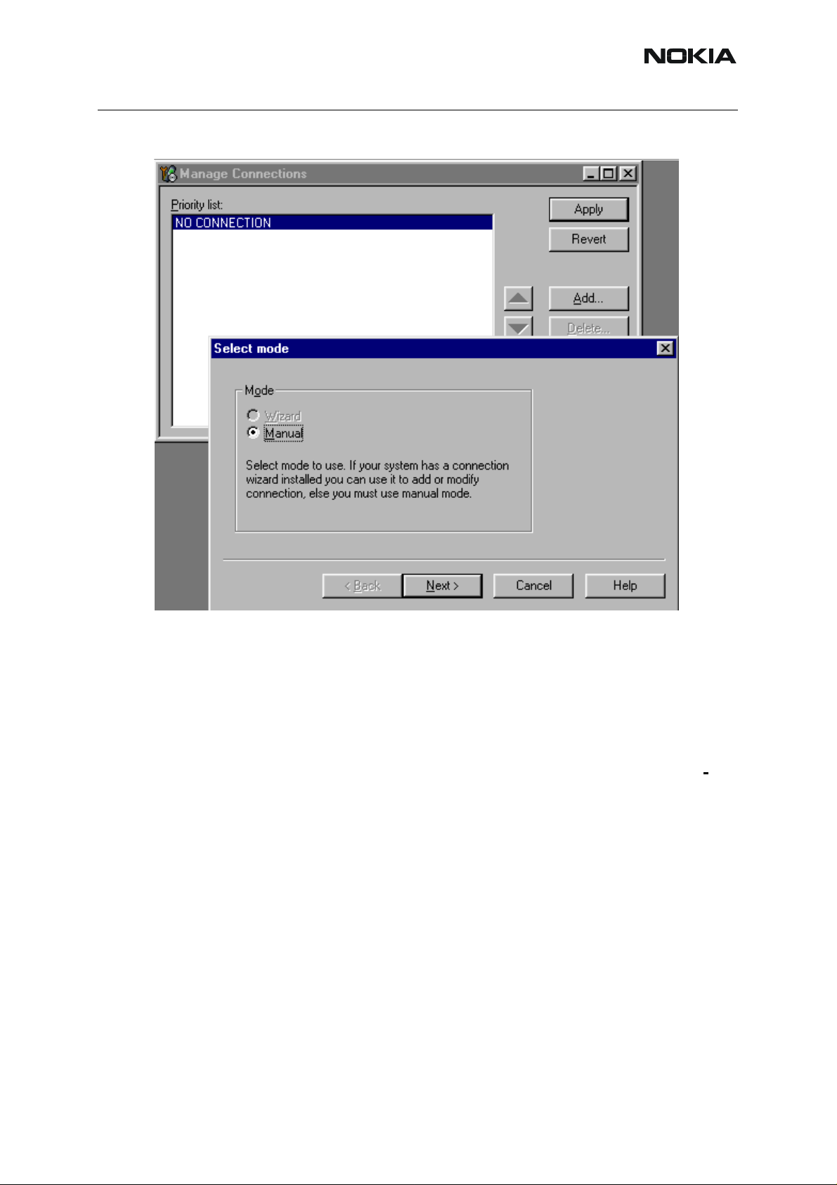
2. From the “File” menu, select “Manage Connections”
Existing connections can be selected, edited, deleted and new ones created by
using this dialog.
You can create a connection either manually or by using a Connection Wizard.
3. To add new connection, click “Add” and select if you want to create it manually
or by using the Wizard.
4. To continue, click “Next”.
20 COMPANY CONFIDENTIAL Issue 3 05/2004
Copyright © 2005 Nokia. All Rights Reserved.
Page 21
NHL-12
3 - Service Software Instructions Nokia Customer Care
5. In the next dialog box you are asked to select some settings for t he connection
Manual settings:
A) For FLS-4S POS Flash Device choose the following connection settings:
- Media: FBUS
- COM Port: Virtual COM Port used by FLS-4S. Please check this always!
(To check the settings, please go to Windows / Control Panel / FLS Virtual Port /
Configuration)
B) For FPS-8 Flash Prommer choose the following connection settings:
- Media: FPS-8
- Port Num: COM Port where FPS-8 is connected
- COMBOX_DEF_MEDIA: FBUS
6. To complete, click “Finish”.
If you use the Wizard, connect the tools and a phone to your PC and the wizard
automatically tries to configure the correct connection.
Issue 3 05/2004 COMPANY CONFIDENTIAL 21
Copyright © 2005 Nokia. All Rights Reserved.
Page 22
NHL-12
Nokia Customer Care 3 - Service Software Instructions
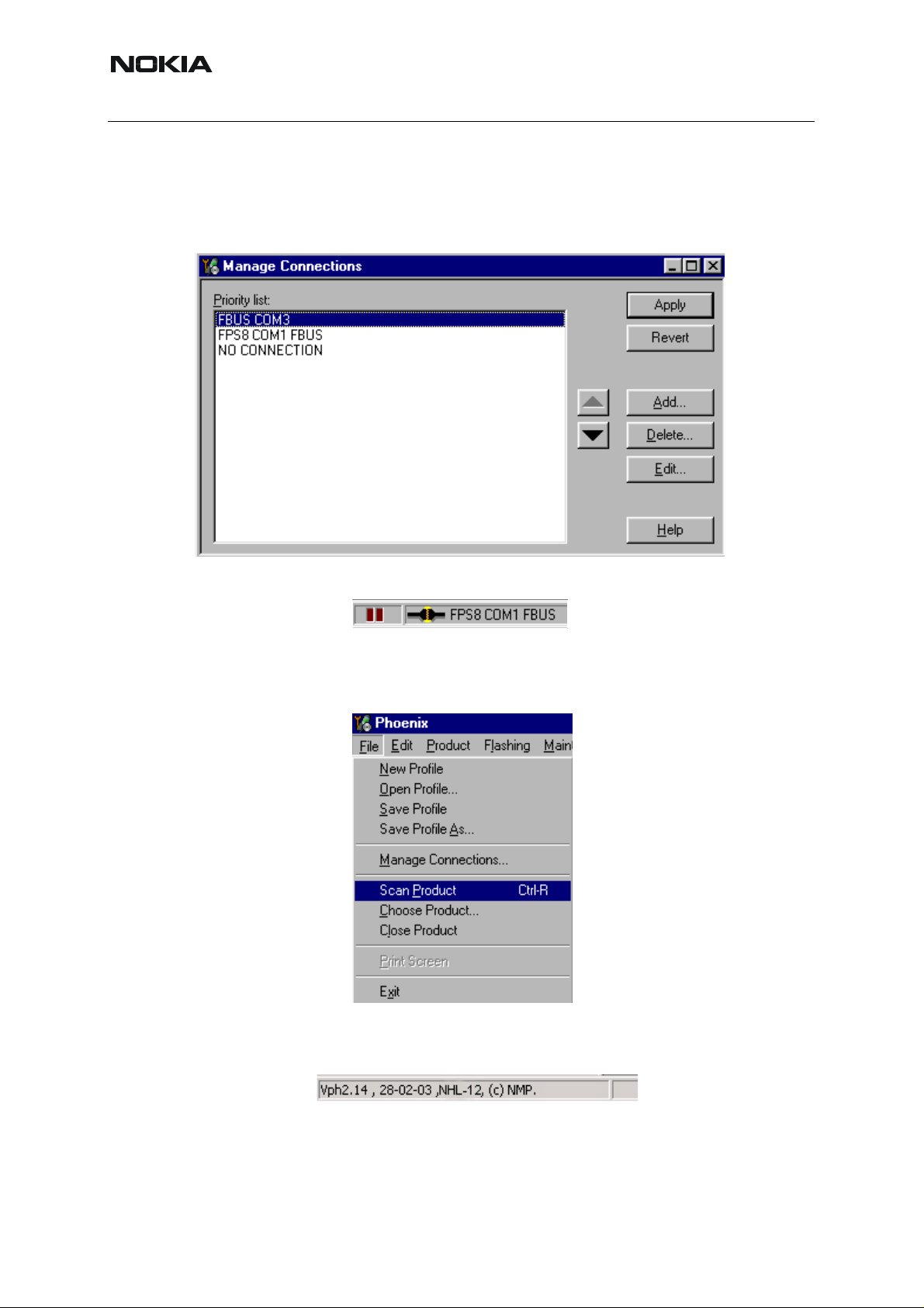
7. To activate the connection you want to use, click it and use up/down arrows to
move it on top of the list. Click “Apply”.
The connection is now selected and can be used after closing the “Ma nage Co nnections” window.
Selected connection is shown in the right-hand bottom corner of the screen.
8. To use the selected connection, connect the phone to Phoenix with correct
service tools. Make sure that it is switched on and choose “Scan Product” from
the File menu.
When the product is found, Phoenix loads product support. When everything is
ready, the name of the loaded product support module and its version are shown
at the bottom of the screen.
22 COMPANY CONFIDENTIAL Issue 3 05/2004
Copyright © 2005 Nokia. All Rights Reserved.
Page 23

NHL-12
3 - Service Software Instructions Nokia Customer Care
4. Updating Flash Support Files for FPS-8* and FLS4S*
■ Before installation
• Install Phoenix service SW and Phoenix data package.
• Install the phone model specific data package for Phoenix.
• The flash support files are delivered in the same installation package with Phoenix
data package.
• Normally it is enough to install the data package only before updating the FPS-8.
• Separate installation package for flash support files is available, and the files can
be updated according to instructions in this chapter.
■ Installing the flash support files
To start installing:
1. Double-click the flash update file (for example, flash_update_02_10_00.exe.)
Installation begins.
2. If you already have the same flash update package files installed, you need to
confirm if you want them to be reinstalled.
Issue 3 05/2005 COMPANY CONFIDENTIAL 23
Copyright © 2005 Nokia. All Rights Reserved.
Page 24

NHL-12
Nokia Customer Care 3 - Service Software Instructions
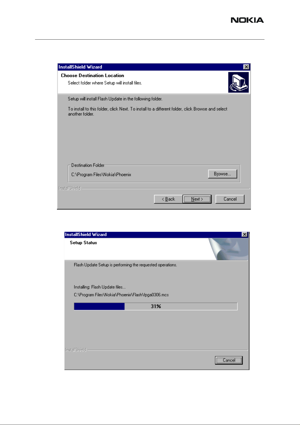
3. To continue installation, click “Next”.
It is highly recommended to install the files to the default destination folder
C:\Program Files\Nokia\Phoenix.
4. To continue, click “Next”.
24 COMPANY CONFIDENTIAL 2005
Copyright © 2005 Nokia. All Rights Reserved.
Page 25
NHL-12
3 - Service Software Instructions Nokia Customer Care
To choose another location, click “Browse” (not recommended).
Installation continues.
Issue 3 05/2005 COMPANY CONFIDENTIAL 25
Copyright © 2005 Nokia. All Rights Reserved.
Page 26
NHL-12
Nokia Customer Care 3 - Service Software Instructions
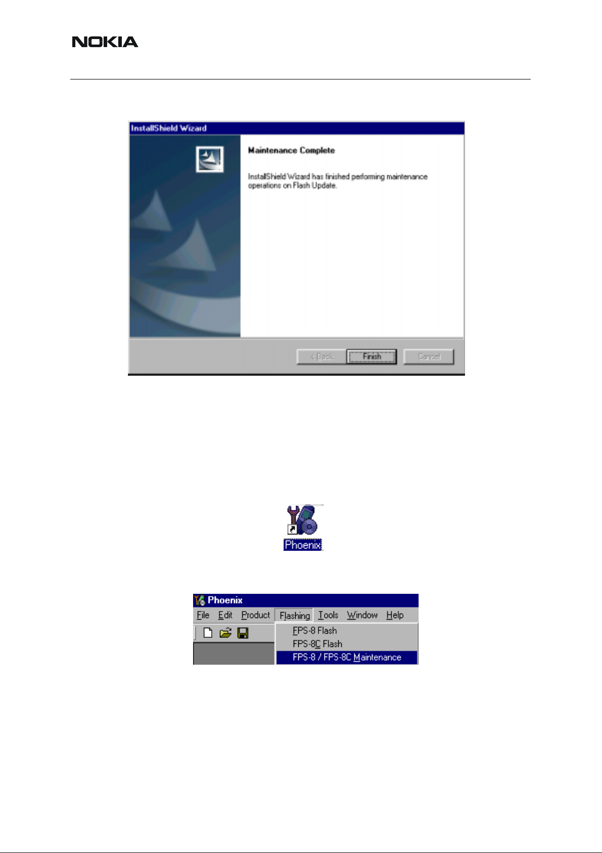
5. To complete the procedure, click “Finish”.
FLS-4S can be used right after flash update package is installed.
FPS-8* must be updated by using Phoenix!
■ Updating FPS-8* flash prommer SW
To start updating:
1. Start Phoenix service software
2. From the ”Flashing” menu, select ”FPS-8 / FPS-8C Maintenance”.
3. When new FPS-8 flash update package is installed to computer, you are asked
to update the files to your FPS-8 prommer.
26 COMPANY CONFIDENTIAL 2005
Copyright © 2005 Nokia. All Rights Reserved.
Page 27

NHL-12
3 - Service Software Instructions Nokia Customer Care
To update files, click ”Yes”.
You can also update FPS-8 software by pressing ”Update” button and selecting appropriate fps8upd.ini file under the C:\Program Files\Nokia\Phoenix\Flash directory.
The update procedure takes a couple of minutes.
Issue 3 05/2005 COMPANY CONFIDENTIAL 27
Copyright © 2005 Nokia. All Rights Reserved.
Page 28

NHL-12
Nokia Customer Care 3 - Service Software Instructions
4. All files can be loaded separately to FPS-8. To do this, press the right mouse button in the “Flash box files” window and select the file type to be loaded.
More information and help can be found from the “Help” dialog.
28 COMPANY CONFIDENTIAL 2005
Copyright © 2005 Nokia. All Rights Reserved.
Page 29

NHL-12
3 - Service Software Instructions Nokia Customer Care
5. Activating and Deactivating FPS-8
• Before the FPS-8 can be successfully used for phone programming, it must be
first activated.
• If there is a need to send FPS-8 box to repair for example, the box must be first
deactivated.
■ Activating FPS-8
To activate:
1. Fill in first “FPS-8 activation request” sheet included in the FPS-8 sales package and follow the instructions in the sheet.
2. When activation file is received (e.g. 00000.in), copy it to C:\Program-
Files\Nokia\Phoenix\BoxActivation directory on your computer (This directory
is created when Phoenix is installed).
3. Start Phoenix service software.
4. From the ”Flashing” menu, select ”FPS-8 / FPS-8C Maintenance”.
Issue 3 05/2005 COMPANY CONFIDENTIAL 29
Copyright © 2005 Nokia. All Rights Reserved.
Page 30

NHL-12
Nokia Customer Care 3 - Service Software Instructions
5. From the “FPS8/8C Maintenance” window, click “Activate”.
6. The activation file you saved to C:\ProgramFiles\Nokia\Phoenix\BoxActiva-
tion directory is shown (e.g. 00000.in). Check that it is correct.
7. To activate the box, click “Open”.
8. To complete activation, turn FPS-8 power off and on.
30 COMPANY CONFIDENTIAL 2005
Copyright © 2005 Nokia. All Rights Reserved.
Page 31

NHL-12
3 - Service Software Instructions Nokia Customer Care
■ Deactivating FPS-8
To deactivate:
1. Start Phoenix service software.
2. From the ”Flashing” menu, select ”FPS-8 / FPS-8C Maintenance”.
3. In the “FPS8/8C Maintenance” window, click “Deactivate”.
4. To confirm deactivation, click “Yes”.
5. To complete deactivation, turn FPS-8 power off and on.
Issue 3 05/2005 COMPANY CONFIDENTIAL 31
Copyright © 2005 Nokia. All Rights Reserved.
Page 32

NHL-12
Nokia Customer Care 3 - Service Software Instructions
6. JBV-1 Docking Station Software
The JBV-1 docking station is a common tool for all DCT-4 generation products. In order to
make the JBV-1 usable with different phone models, a phone specific docking station adapte r
is used for different service functions.
The JBV-1 docking station contains software (Firmware) which can be updated.
You need the following equipment to be able to update JBV-1 software:
• PC with USB connection
• Operating system supporting USB (Not Win 95 or NT)
• USB cable (can be purchased from shops or suppliers providing PC hardware
and accessories)
• JBV-1 docking station
• External power supply 11-16V
■ Before installation
• From your download web site, download Jbv1_update.zip file to your computer
(e.g. C:\TEMP).
• Close all other programs.
• Follow instructions on the screen.
■ Installing software needed for the JBV-1 SW update
Note: DO NOT CONNECT THE USB CABLE / JBV-1 TO YOUR COMPUTER YET!
1. Run the Jbv1_update.zip file.
2. To start SW Installation, double-click Setup.exe
3. To continue, click “OK”.
Files needed for JBV-1 package setup program are extracted and installation begins.
32 COMPANY CONFIDENTIAL 2005
Copyright © 2005 Nokia. All Rights Reserved.
Page 33

NHL-12
3 - Service Software Instructions Nokia Customer Care
4. Please read the information shown and click “Next” to continue.
5. Use the suggested destination folder where JBV-1 SW package is installed.
6. To continue, click “Next”.
7. Select “Full” installation.
Issue 3 05/2005 COMPANY CONFIDENTIAL 33
Copyright © 2005 Nokia. All Rights Reserved.
Page 34

NHL-12
Nokia Customer Care 3 - Service Software Instructions
8. To continue, click “Next”.
The Program Folder is created.
9. To continue, click “Next”.
Software files are installed.
34 COMPANY CONFIDENTIAL 2005
Copyright © 2005 Nokia. All Rights Reserved.
Page 35

NHL-12
3 - Service Software Instructions Nokia Customer Care
10.After successful installation, click “Finish” to complete.
NOW YOU CAN CONNECT THE USB CABLE / JBV-1 TO YOUR COMPUTER!
11.Connect power to JBV-1 (11-16V DC) from external power supply.
12.Connect the USB cable between JBV-1 USB connector and your PC.
Windows detects the connected USB cable and drivers for new HW.
13.Follow the instructions and allow Windows to search and install the best drivers available. After this procedure the actual JBV-1 SW update can begin.
Issue 3 05/2005 COMPANY CONFIDENTIAL 35
Copyright © 2005 Nokia. All Rights Reserved.
Page 36

NHL-12
Nokia Customer Care 3 - Service Software Instructions
■ Updating JBV-1 docking station software
To update the JBV-1 docking station software:
1. Go to folder C:\Program Files\Nokia\ JBV-1 SW Package\ FIRMWARE UPDATE.
2. To start JBV-1 update SW, double-clicking fwup.exe.
JBV-1 firmware update starts and shows the current status of the JBV-1 connected.
3. If the firmware version read from your JBV-1 is not the latest one available, it
needs to be updated. To update, click “Update Firmware”.
4. Choose file JBV1v11.CDE (example used here is for v 11).
5. To update your JBV-1, click “Open”.
After a successful update, the current JBV-1 status is shown. You have now updated
the software of your JBV-1 docking station and it is ready for use.
36 COMPANY CONFIDENTIAL 2005
Copyright © 2005 Nokia. All Rights Reserved.
Page 37

NHL-12
3 - Service Software Instructions Nokia Customer Care
7. Receiver Tuning: Quick Guide for Tuning with Phoenix
■ General remarks
• RF tunings must be performed in the same order as shown in this document. The
order of the corresponding menu items in the service SW may be different.
• If baseband tunings are needed, they should be completed before RF tunings.
• Avoid unnecessary tuning – factory-tuning values are always the most accurate
ones.
NOTE! RF tunings need to be done ONLY if any RF block component is replaced.
• Screenshots described in this document may change as the service software is
developed.
• Kindly refer to the Phoenix help files, the phone model specific service manual
and technical bulletins for help.
Issue 3 05/2004 COMPANY CONFIDENTIAL 37
Copyright © 2005 Nokia. All Rights Reserved.
Page 38

NHL-12
Nokia Customer Care 3 - Service Software Instructions
■ Service tool concept for RF tuning operations
NOTE! RF tunings need to be done ONLY if any RF block component is replaced.
• All RF tuning operations must be carried out in the MJ-13 module jig!
• Power to MJ-13 must be supplied from an external DC power supply, not from the
FPS-8 prommer
• MJ-13 input voltages:
- Maximum + 12 VDC (Regulated mode)
- Maximum + 4.6 VDC (Bypass mode)
- Nominal input for RF tunings is +4.2 VDC (Bypass mode)
• Remember the cable attenuation when setting required RF levels
Figure 1:RF tuning setup
5
6
4
2
3
Item Service accessory Type
1
Product
code
1 Module jig MJ-13 0770666
2 DC power cable PCS-1 0730012
3 Modular cable XRF-1 0730085
4 Service Mbus cable DAU-9S 0730108
5 Software protection key PKD-1 0750018
6Service SW CD-ROM
38 COMPANY CONFIDENTIAL 2005
Copyright © 2005 Nokia. All Rights Reserved.
Page 39

NHL-12
3 - Service Software Instructions Nokia Customer Care
■ Autotuning
Autotune feature is designed to align product’s RF part easier and faster. By this autotune component, the product is tuned automatically. The user only needs to press ‘Tune’ and the product’s RF is tuned and results are shown to the user. Component controls all the needed RF
equipment (RF generator and Tx measuring device) except voltage supplier.
NOTE! Automatic tuning is ALWAYS the primary tuning mode.
The following diagram describes how the autotune component is located in the TSS architecture:
Figure 2:Autotune component in TSS architecture
Auto tun e U I
Au totu n e F N
Manual tune FNs
MTI
Phone
GP IB Eq uipm e nt
Autotune is a pair of two different components. One is User Interface and the other is FunctioNal. UI does not contain any functionality. MTI takes care of phone messages.
The Autotune component can be found under the Tuning menu:
Figure 3:Autotune menu in Phoenix
Issue 3 05/2004 COMPANY CONFIDENTIAL 39
Copyright © 2005 Nokia. All Rights Reserved.
Page 40

NHL-12
Nokia Customer Care 3 - Service Software Instructions
Figure 4:Autotune menu - RX/TX menu
Set loss
Figure 5:Set Loss menu
This is the component for saving RF-losses (of cables and jigs) to file. These loss values are
needed when you tune the phone with Phoenix (using Auto-Tune component). When you
measure the losses you have to be very careful, because these value s affect directly how well
the phone is tuned.
NOTE! This component is only for Auto-Tune uses.
Figure 6:Loss values
Environment
Hardware requirements:
PC with Windows 98/2000/NT
40 COMPANY CONFIDENTIAL 2005
Copyright © 2005 Nokia. All Rights Reserved.
Page 41

NHL-12
3 - Service Software Instructions Nokia Customer Care
Power supply
Product specific module jig
RF-splitter and -cables
RF equipment (only one of each is needed)
Tx:
Agilent E4406 (VSA series transmitter tester)
Agilent E4445 (PSA series transmitter tester)
Rohde&Schwarz, FSE-family of signal analyzers
Rohde&Schwarz, FSIQ-family of signal analyzers
Rx:
Agilent ESG family of RF signal generators
Rohde&Schwarz, SME-family of signal generators
Figure 7:Setup environment
GPIB addresses are not defined. Component finds the addresses and uses them automatically.
If several Tx tuning devices are connected, this component uses Agilent (VSA or PSA). On the
Rx side, Agilent has the highest priority.
Protection
Components are protected by PKD-1CS, PKD-1NS, PKD-1 and PKD-1P dongles using standard TSS protection procedure. Autotuning itself is possible with all these dongles b ut with PKD1P and PKD-1 dongles user is not able to set the loss.
Issue 3 05/2004 COMPANY CONFIDENTIAL 41
Copyright © 2005 Nokia. All Rights Reserved.
Page 42

NHL-12
Nokia Customer Care 3 - Service Software Instructions
■ Receiver manual tuning
Rx Channel Select Filter Calibration
• Extra equipment / external RF signal is not needed.
• Must be done before other Rx calibrations.
• This function is used to calibrate Rx channel select filter in GSM phones.
• Rx channel select filter is tuned only in one band = Single calibration for every
band.
To start calibrating:
1. From the “Tuning” menu, choose “Rx Channel Select Filter Calibration”.
2. To start the tuning, click "Tune".
Tuning values must be 0…31
“Save to Phone “is checked by default
If you do not want the values to be saved to phone, uncheck “Save to Phon e “ (e.g.
testing).
3. If values shown are within limits, click “Stop”
4. To end tuning, and to save the values to the phone, close the “Rx Channel Select
Filter Calibration“ dialog box.
Rx Calibration
• RF generator is needed.
• This tuning performs Rx calibration.
42 COMPANY CONFIDENTIAL 2005
Copyright © 2005 Nokia. All Rights Reserved.
Page 43

NHL-12
3 - Service Software Instructions Nokia Customer Care
• Must be done separately on every band!
• Calibration is automatically performed at GSM850, then at GSM1800 and finally
at GSM1900 band. If tuning is successful, it continues in the next band
• AFC tuning is done while GSM850 band Rx Calibration is performed
Note! Remember to take jig and cable attenuations into account!
To start calibrating:
1. From the “Tuning” menu, choose “Rx Calibration”.
2. To start tuning, click “Calibrate".
3. Set RF generator to required GSM850 frequency => OK.
4. Set RF generator to required GSM850 frequency => OK.
Tuning values and ADC readings are shown.
Issue 3 05/2004 COMPANY CONFIDENTIAL 43
Copyright © 2005 Nokia. All Rights Reserved.
Page 44

NHL-12
Nokia Customer Care 3 - Service Software Instructions
Table 1: Typical values and limits in (GSM850) Rx calibration
GSM850 Typical value Low limit High limit
Afc value: -90 -350 350
Afc slope:
Rssi 0: 65.09375 58 68
Rssi 1: 71.09375 64 74
Rssi 2: 76.90625 70 80
Rssi 3: 82.90625 76 86
Rssi 4: 88.90625 82 92
Rssi 5: 93.71875 88 98
Rssi 6: 99.71875 94 104
Rssi 7: 105.53125 100 110
Rssi 8: 111.53125 106 116
Rssi 9: 117.53125 112 122
Rssi 10: 123.53125 118 128
Rssi 11: 129.53125 124 134
Rssi 12: 135.53125 130 140
270 150 350
Rssi 13: 141.53125 136 146
Rssi 14: 147.53125 142 152
5. Set RF generator to required GSM1800 frequency => OK.
Tuning values and ADC readings are shown.
44 COMPANY CONFIDENTIAL 2005
Copyright © 2005 Nokia. All Rights Reserved.
Page 45

NHL-12
3 - Service Software Instructions Nokia Customer Care
Table 2: Typical values and limits in (GSM1800) Rx calibration
GSM1800 Typical value Low limit High limit
Rssi 0: 62.40625 58 68
Rssi 1: 68.40625 64 74
Rssi 2: 74.265625 70 80
Rssi 3: 80.265625 76 86
Rssi 4: 86.265625 82 92
Rssi 5: 91.859375 88 98
Rssi 6: 97.859375 94 104
Rssi 7: 103.71875 100 110
Rssi 8: 109.71875 106 116
Rssi 9: 115.71875 112 122
Rssi 10: 121.71875 118 128
Rssi 11: 127.71875 124 134
Rssi 12: 133.71875 130 140
Rssi 13: 139.71875 136 146
Rssi 14: 145.71875 142 152
6. Set the RF generator to required GSM1900 frequency => OK.
Tuning values and ADC readings are shown.
Issue 3 05/2004 COMPANY CONFIDENTIAL 45
Copyright © 2005 Nokia. All Rights Reserved.
Page 46

NHL-12
Nokia Customer Care 3 - Service Software Instructions
Table 3: Typical values and limits in (GSM1900) Rx calibration
GSM1900 Typical value Low limit High limit
Rssi 0: 66.25 61 71
Rssi 1: 72.25 67 77
Rssi 2: 78.09375 73 83
Rssi 3: 84.09375 79 89
Rssi 4: 90.09375 85 95
Rssi 5: 93.25 88 98
Rssi 6: 99.25 94 104
Rssi 7: 105.09375 100 110
Rssi 8: 111.09375 106 116
Rssi 9: 117.09375 112 122
Rssi 10: 123.09375 118 128
Rssi 11: 129.09375 124 134
Rssi 12: 135.09375 130 140
Rssi 13: 141.09375 136 146
Rssi 14: 147.09375 142 152
If values are within limits, they are saved to the phone after successful tuning of each band.
7. To end tuning, close the “Rx Calibration” dialog box.
Rx Band Filter Response Compensation
• RF generator is needed.
• This operation must be done separately on every band!
• Start Rx calibration at GSM850, then continue at GSM1800 band and finally on
the GSM1900 band.
NOTE! Remember to do Rx calibration before doing Rx Band Filter Response Compensation!
Remember to take jig and cable attenuations into account!
To start Rx band filter response compensation:
46 COMPANY CONFIDENTIAL 2005
Copyright © 2005 Nokia. All Rights Reserved.
Page 47

NHL-12
3 - Service Software Instructions Nokia Customer Care
1. From the “Tuning” menu, choose “Rx Band Filter Response Compensation”.
2. To start tuning with values already saved to the phone, click “Yes”.
3. To start tuning, click "Manual tuning".
You are asked to supply 9 different RF frequencies to the phone.
The tuning begins from the GSM850 band and continues the same way for the
GSM1800 and GSM1900 bands.
Issue 3 05/2004 COMPANY CONFIDENTIAL 47
Copyright © 2005 Nokia. All Rights Reserved.
Page 48

NHL-12
Nokia Customer Care 3 - Service Software Instructions
4. Set the first required frequency and level => OK.
5. Set the 2nd required frequency and level => OK.
6. Set the 3rd required frequency and level => OK.
7. Set the 4th required frequency and level => OK.
8. Set the 5th required frequency and level => OK.
48 COMPANY CONFIDENTIAL 2005
Copyright © 2005 Nokia. All Rights Reserved.
Page 49

NHL-12
3 - Service Software Instructions Nokia Customer Care
9. Set the 6th required frequency and level => OK.
10.Set the 7th required frequency and level => OK.
11.Set the 8th required frequency and level => OK.
12.Set 9th required frequency and level => OK.
Table 4: Typical values and limits in Rx Band Filter Response Compensation GSM850:
Input
Channel
Frequency (MHz)
Low limit (dB) High limit (dB)
118 863.26771 -10 3.5
128 869.26771 -3.5 3.5
140 871.66771 -3.5 3.5
172 878.06771 -3.5 3.5
190 881.66771 -3.5 3.5
217 887.06771 -3.5 3.5
241 891.86771 -3.5 3.5
251 893.86771 -3.5 3.5
261 895.86771 -10 3.5
13.Click "Stop, write to PM area".
Issue 3 05/2004 COMPANY CONFIDENTIAL 49
Copyright © 2005 Nokia. All Rights Reserved.
Page 50

NHL-12
Nokia Customer Care 3 - Service Software Instructions
14.If the values shown are within limits, click “Yes” to save values to the phone.
15.To continue tuning from GSM1800, choose the correct band from the dropdown menu.
Repeat the same steps as for the GSM850 band above.
Table 5: Typical values and limits in Rx Band Filter Response Compensation GSM1800:
Input
Channel
Frequency (MHz)
Low limit (dB) High limit (dB)
497 1802.26771 -10 3.5
512 1805.26771 -3.5 3.5
535 1809.86771 -3.5 3.5
606 1824.06771 -3.5 3.5
700 1842.86771 -3.5 3.5
791 1861.06771 -3.5 3.5
870 1876.86771 -3.5 3.5
885 1879.86771 -3.5 3.5
908 1884.46771 -10 3.5
16.Click "Stop, write to PM area".
17.If the values shown are within limits, click “Yes” to save values to the phone.
18.To continue tuning from GSM1900, choose the correct band from the dropdown menu.
Repeat the same steps as for the GSM850 and GSM1800 bands above.
50 COMPANY CONFIDENTIAL 2005
Copyright © 2005 Nokia. All Rights Reserved.
Page 51

NHL-12
3 - Service Software Instructions Nokia Customer Care
Table 6: Typical values and limits in Rx Band Filter Response Compensation GSM1900:
Input
Channel
Frequency (MHz)
496 1927.06771 -10 3.5
512 1930.26771 -3.5 3.5
537 1935.26771 -3.5 3.5
586 1945.06771 -3.5 3.5
661 1960.06771 -3.5 3.5
736 1975.06771 -3.5 3.5
794 1986.66771 -3.5 3.5
810 1989.86771 -3.5 3.5
835 1994.86771 -10 3.5
19.Click "Stop, write to PM area".
20.If the values shown are within limits, click “Yes” to save values to the phone.
21.Close the “Rx Band Filter Response Compensation” dialog box to end tuning.
Low limit (dB) High limit (dB)
Rx Am Suppression
• RF generator is needed.
• Must be done separately on every band!
• Start Rx Am Suppression at GSM850, then continue at GSM1800 band and finally
at the GSM1900 band.
Note! Remember to take jig and cable attenuations into account!
To start Rx Am Suppression:
1. From the “Tuning” menu, choose “Rx Am Suppression”.
Issue 3 05/2004 COMPANY CONFIDENTIAL 51
Copyright © 2005 Nokia. All Rights Reserved.
Page 52

NHL-12
Nokia Customer Care 3 - Service Software Instructions
2. To begin tuning, click “Start”.
3. Adjust signal generator accordingly and click “OK” to tune.
4. When tuning is finished, click “Save & Continue”.
Tuning continues automatically at the GSM1800 band.
52 COMPANY CONFIDENTIAL 2005
Copyright © 2005 Nokia. All Rights Reserved.
Page 53

NHL-12
3 - Service Software Instructions Nokia Customer Care
5. Adjust signal generator accordingly and click “OK” to tune.
6. When tuning is finished, click “Save & Continue”.
7. Tuning continues automatically at the GSM1900 band.
8. Adjust signal generator accordingly and click “OK” to tune.
Issue 3 05/2004 COMPANY CONFIDENTIAL 53
Copyright © 2005 Nokia. All Rights Reserved.
Page 54

NHL-12
Nokia Customer Care 3 - Service Software Instructions
9. When tuning is finished, click “Save & Continue”.
10.If the Rx Am Suppression tuning was completed successfully, click “OK” to
stop tuning.
11.Close the Rx Am Suppression window.
54 COMPANY CONFIDENTIAL 2005
Copyright © 2005 Nokia. All Rights Reserved.
Page 55

NHL-12
3 - Service Software Instructions Nokia Customer Care
■ T ransmitter manual tuning
Tx Power Level Tuning
• A power meter or a spectrum analyzer is needed.
• With Tx Power Level Tuning, the coefficients are adjusted for each power level.
• Start power level tuning at GSM850/EDGE, then continue at GSM1800/EDGE
band and finally at the GSM1900/EDGE band.
• In the GSM tuning, set data type to "Random".
• In the EDGE tuning, set data type to "All 0's". If you use "Alternate PN9", you need
to tune power levels 1dBm lower than the target levels.
To start Tx Power Level Tuning:
1. From the “Tuning” menu, choose “Tx Power Level Tuning”.
2. Click “Start”. Tuning begins at the GSM850 band
3. Set up spectrum analyzer accordingly.
Issue 3 05/2005 COMPANY CONFIDENTIAL 55
Copyright © 2005 Nokia. All Rights Reserved.
Page 56

NHL-12
Nokia Customer Care 3 - Service Software Instructions
Remember to take the jig and cable attenuations into account!
The coefficient table lists the power level, coefficient, and target dBm for each
power level.
4. To choose the tuned power level, use up and down arrows or mouse.
The current power level is shown with inverse colours.
5. To adjust the tuning value, use “-“ and “+” keys.
6. Tune base level and power levels 19, 15 and 5 to target level.
56 COMPANY CONFIDENTIAL Issue 3 05/2005
Copyright © 2005 Nokia. All Rights Reserved.
Page 57

NHL-12
3 - Service Software Instructions Nokia Customer Care
7. Click “Save & Continue”. Tuning values are calculated and saved to phone’s
memory.
Tuning continues at EDGE850.
8. Set up spectrum analyzer accordingly.
9. To start tuning, click “OK”.
10.Tune all power levels to target level.
Note! Target for EDGE Base level is -15dBm.
Issue 3 05/2005 COMPANY CONFIDENTIAL 57
Copyright © 2005 Nokia. All Rights Reserved.
Page 58

NHL-12
Nokia Customer Care 3 - Service Software Instructions
11.To save the tuning values to phone’s memory, click “Save & Continue”.
Continue tuning at GSM1800 band
12.Set up spectrum analyzer accordingly.
Remember to take the jig and cable attenuations into account!
13.To start tuning, click “OK”.
58 COMPANY CONFIDENTIAL Issue 3 05/2005
Copyright © 2005 Nokia. All Rights Reserved.
Page 59

NHL-12
3 - Service Software Instructions Nokia Customer Care
14.Tune base level and power levels 15,11 and 0 to target level.
15.TClick “Save & Continue”.
Tuning values are calculated and saved to the phone’s memory.
Tuning continues at EDGE1800.
16.Set up spectrum analyzer accordingly.
17.To start tuning, click “OK”.
Issue 3 05/2005 COMPANY CONFIDENTIAL 59
Copyright © 2005 Nokia. All Rights Reserved.
Page 60

NHL-12
Nokia Customer Care 3 - Service Software Instructions
18.Tune all power levels to target level.
Note! Target for EDGE Base level is -15dBm.
19.To save the tuning values to phone’s memory, click “Save & Continue”.
Continue tuning at GSM1900 band.
20.Set up spectrum analyzer accordingly.
Remember to take the jig and cable attenuations into account!
60 COMPANY CONFIDENTIAL Issue 3 05/2005
Copyright © 2005 Nokia. All Rights Reserved.
Page 61

NHL-12
3 - Service Software Instructions Nokia Customer Care
21.To start tuning, click “OK”.
22.Tune base level and power levels 15, 11, 3 and 0 to target level.
Note! Target for power level 0 is 30 dBm at GSM1900 band.
23.Click “Save & Continue”.
Tuning values are calculated and saved to phone’s memory
Tuning continues at EDGE1900.
Issue 3 05/2005 COMPANY CONFIDENTIAL 61
Copyright © 2005 Nokia. All Rights Reserved.
Page 62

NHL-12
Nokia Customer Care 3 - Service Software Instructions
24.Set up spectrum analyzer accordingly.
25.To start tuning, click “OK”.
26.Tune all power levels to target level.
Note! Target for EDGE Base level is -15dBm.
27.To save the tuning values to phone’s memory, click “Save & Continue” .
Tx Power Level Tuning is now completed.
62 COMPANY CONFIDENTIAL Issue 3 05/2005
Copyright © 2005 Nokia. All Rights Reserved.
Page 63

NHL-12
3 - Service Software Instructions Nokia Customer Care
Tx I/Q Tuning
• Spectrum analyzer is needed
• Tx IQ tuning allows changing the Tx I DC offset, Tx Q DC offset, amplitude difference and phase difference.
• Must be done separately on all bands!
1. From the “Tuning” menu, choose “Tx_IQ Tuning”.
Tx IQ Tuning window opens.
2. To begin tuning at the GSM850 band, click “Start”.
Issue 3 05/2005 COMPANY CONFIDENTIAL 63
Copyright © 2005 Nokia. All Rights Reserved.
Page 64

NHL-12
Nokia Customer Care 3 - Service Software Instructions
3. Adjust spectrum analyzer accordingly.
4. To start tuning, click “OK”.
5. To tune, set each of the sliders to a desired value.
The order of tuning should be the same as the order of the sliders, that is, the Tx
I DC Offset is tuned first and Phase difference is tuned last.
Use <= , =>, PgUp or PgDn keys.
6. Tune LO leakage to minimum with TxI/TxQ DC Offset control (f0 on spectrum
analyzer screen).
64 COMPANY CONFIDENTIAL Issue 3 05/2005
Copyright © 2005 Nokia. All Rights Reserved.
Page 65

NHL-12
3 - Service Software Instructions Nokia Customer Care
7. Tune undesired sideband to minimum using Amplitude/Phase difference controls (f0 + 67.71kHz on spectrum analyzer screen).
LO leakage
Unwanted sid eband
LO leakage and unwanted
sideband are tuned to
minimum
Tuning limits are the same for all bands (GSM/EDGE850, GSM/EDGE1800 and GSM/
EDGE1900).
Issue 3 05/2005 COMPANY CONFIDENTIAL 65
Copyright © 2005 Nokia. All Rights Reserved.
Page 66

NHL-12
Nokia Customer Care 3 - Service Software Instructions
Table 7: Tuning limits for GSM/EDGE850, GSM/EDGE1800 and GSM/EDGE1900
Tuning limits
I DC Offset -6…+6
Q DC Offset -6…+6
Amplitude difference -1…+1
Phase difference - 80°…100°
8. When the IQ spectrum is balanced, click “Save & Continue” to continue
EDGE850 Tx IQ tuning.
Spectrum analyzer settings are the same as for GSM850 IQ tuning.
NOTE! In EDGE-mode, the unwanted sideband is located at 50.8kHz from f0.
50.8kHz
9. When the IQ spectrum is balanced, click “Save & Continue”.
Continue tuning at GSM/EDGE1800 band.
66 COMPANY CONFIDENTIAL Issue 3 05/2005
Copyright © 2005 Nokia. All Rights Reserved.
Page 67

NHL-12
3 - Service Software Instructions Nokia Customer Care
10.Adjust spectrum analyzer accordingly.
Both GSM and EDGE 1800 use the same settings.
Continue tuning at GSM/EDGE1900 band
11.Adjust spectrum analyzer accordingly.
Both GSM and EDGE1900 use the same settings.
12.When GSM and EDGE1900 are tuned, click “Save & Continue”.
Issue 3 05/2005 COMPANY CONFIDENTIAL 67
Copyright © 2005 Nokia. All Rights Reserved.
Page 68

NHL-12
Nokia Customer Care 3 - Service Software Instructions
13.To complete the Tx IQ Tuning, click “OK”.
68 COMPANY CONFIDENTIAL Issue 3 05/2005
Copyright © 2005 Nokia. All Rights Reserved.
Page 69

NHL-12
3 - Service Software Instructions Nokia Customer Care
8. Service Tool Concept for Baseband Tuning Operations
EM calibrations should be carried out in JBV-1 docking station equipped with DA-9 dockin g station adapter.
Power to JBV-1 should be supplied from an external DC power supply, not
prommer.
JBV-1 input voltages:
• Maximum +16 VDC
• Nominal input for RF tunings is +12 V DC
Figure 8:Service concept for NHL-12 baseband tunings
8
6
4
from the FPS-8
7
3
5
2
1
Item Accessory type Service accessory Product code
1 JBV-1 Docking station 0770298
2 DA-9 Docking station adapter 0770663
3 SCB-3 DC-DC cable 0730114
5 PCS-1 DC power cable 0730012
6 DAU-9S Service FBUS cable 0730108
7 PKD-1 Software protection key 0750018
Issue 3 05/2005 COMPANY CONFIDENTIAL 69
Copyright © 2005 Nokia. All Rights Reserved.
Page 70

NHL-12
Nokia Customer Care 3 - Service Software Instructions
Item Accessory type Service accessory Product code
8 Service SW CD-ROM
70 COMPANY CONFIDENTIAL Issue 3 05/2005
Copyright © 2005 Nokia. All Rights Reserved.
Page 71

NHL-12
3 - Service Software Instructions Nokia Customer Care
9. Baseband Tuning Operations
Energy management calibration
Energy management (EM) calibration is used for calibrating the battery and charger settings of
the phone.
Preparation for EM calibration:
• External power supply is needed.
• Connect the DC cable SCB-3 between JBV-1 and Vin of the phone for charger
calibration
• Connect 12…15 V from the power supply to JBV-1
NOTE! Check that the connection is F-BUS (does not work with M-BUS).
To start energy management calibration:
1. From the “Tuning” menu, choose “Energy Management Calibration”.
Energy management values to be calibrated are checked.
2. To show the current values in the phone memory and to check that the communication with the phone works, click “Read from Phone”.
Issue 3 05/2005 COMPANY CONFIDENTIAL 71
Copyright © 2005 Nokia. All Rights Reserved.
Page 72

NHL-12
Nokia Customer Care 3 - Service Software Instructions
3. To run the selected calibrations, click “Calibrate”.
Table 8: Limits for energy management calibration
Channel Low High Channel
ADC Offset -50 50 ADC Offset
ADC Gain 25400 29500 ADC Gain
BSI Gain 970 1100 BSI Gain
Vbatt Offset 2300 2900 Vbatt Offset
Vbatt Gain 10000 11000 Vbatt Gain
Vchar 58000 63000 Vchar
Ichar 4050 4800 Ichar
lbat 80 150 lbat
4. If values shown are within limits, click “Save To Phone” to save the values in
the phone.
NOTE! Only the values of the checked tunings (Battery size, Battery Temperature
etc.…) are saved.
5. To end tuning, close the “Energy Management Calibration” dialog box.
6. After exiting the dialog box, you must manually switch the phone on.
72 COMPANY CONFIDENTIAL Issue 3 05/2005
Copyright © 2005 Nokia. All Rights Reserved.
Page 73

NHL-12
3 - Service Software Instructions Nokia Customer Care
10. Phoenix Self Tests
Test Description
ST_AUX_DA_LOOP_TEST The test checks connection of AuxDa and UemInt sig-
nals between UPP and UEM.
ST_EAR_DATA_LOOP_TEST The test checks connection of EarData and MicData sig-
nals between UPP and UEM.
ST_IR_LOOP_TEST The purpose of this test is to check that IR device works
properly.
ST_KEYBOARD_STUCK_TEST The purpose of this test is to check that the keyboard is
not stuck, meaning that none of the keyboard keys other
than the power-key is pressed.
ST_MBUS_RX_TX_LOOP_TEST The test checks connection of MBusTx and MBusRx sig-
nals between UPP and UEM.
ST_SIM_CLK_LOOP_TEST The test checks connection of SimClk and SimIODa sig-
nals between UPP and UEM.
ST_SIM_IO_CTRL_LOOP_TEST The test checks connection of SimIOCtrl and SimIODa
signals between UPP and UEM.
ST_SLEEP_X_LOOP_TEST The test checks connection of SleepX and SleepClk sig-
nals between UPP and UEM.
ST_TX_IDP_LOOP_TEST The test checks connection of TxIdp and RxIdp signals
between UPP and UEM.
ST_TX_IQ_DP_LOOP_TEST The test checks connection of TxQdp and RxQdp sig nals
between UPP and UEM.
ST_BACKUP_BATT_TEST The test checks whether the connection to the backup
battery is OK or not.
ST_LPRF_IF_TEST The purpose of this test is to test the Bluetooth interface,
i.e. the BT module
ST_CAMERA_IF_TEST The purpose of this test is to check the camera interface.
ST_WARRANTY_TEST The purpose of this test is to test the warranty informa-
tion state.
ST_FLASH_CHECKSUM_TEST The test is done calculating the checksum over flash
ROM areas and checksum is compared to a pre-calculated checksum in flash header. Note, this test checks
only the CMT side flash, not the APE side flash.
ST_LPRF_AUDIO_LINES_TEST This test is used in Bluetooth PCM loopback test.
ST_UEM_CBUS_IF_TEST The test checks CBUS connection between UPP and
UEM.
Issue 3 05/2005 COMPANY CONFIDENTIAL 73
Copyright © 2005 Nokia. All Rights Reserved.
Page 74

NHL-12
Nokia Customer Care 3 - Service Software Instructions
Test Description
ST_VIBRA_TEST The purpose of this test is to check that the vibra chip is
functional.
ST_SLEEPCLK_FREQ_TEST This function tests the frequency of 32kHz SleepClock
(CRYSTAL).
ST_CURRENT_GAUGE_IF_TEST Zocus current gauge chip is controlled via CBUS. The
test checks whether the connection to the chip is OK or
not.
ST_MAIN_LCD_IF_TEST The purpose of this test is to check all connections
between APE and the main LCD.
ST_APE_DAC_CTRL_IF_TEST Purpose of this test is to check connections (I2C lines)
between APE and DAC
ST_APE_RAM_TEST The test performs a complete test for APE SDRAM from
address zero to end.
ST_APE_POST_CODE_TEST The test checks the latest XBUS postcode sent by APE .
ST_BT_WAKEUP_TEST This test is used in BT wakeup signal test
ST_XABUS_TEST The purpose of this test is to check the communication
link (XABUS) between application-DSP and CDSP.
NOTE! If ST_APE_RAM_TEST or ST_CMT_APE_WAKE_UP_TEST is executed from the Self
Tests window (by running tests one by one or if Select All is clicked), the phone has to be restarted to get reliable results from other tests.
If ST_BT_WAKEUP_TEST is executed, the phone has to re-started before opening the Bluetooth LOCALS window for Bluetooth testing.
74 COMPANY CONFIDENTIAL Issue 3 05/2005
Copyright © 2005 Nokia. All Rights Reserved.
Page 75

NHL-12
3 - Service Software Instructions Nokia Customer Care
11. Flashing Setup Instructions
This section describes the different flashing setups for NHL-12.
In general, after you have connected all the cables and started Phoenix, wait until you see the
Ready status in the status bar before using the Phoenix testing features.
If there is no NOS (Network Operating System) ready, then the application side is not started
up correctly and some Phoenix features which need the application side are not working (user
data back-up, user area formatting, audio control, Bluetooth LOCALS, camera control, d isplay
test, factory settings, keyboard test, MMC control, self tests, USB tests).
■ POS (Point of Sale) flash concept
Figure 9:POS flash setup
Item Type Description Code
1 SF-8 Point Of Sale flash loading adapter 0770665
2 CA-28DS Service data cable 0730319
3 ACF-8 AC Charger 0680032
4 FLS-4S, FLS-4S sales package US 0080543
5 n.a. USB cable n.a.
6 PKD-1 Software protection key 0750018
7 Service SW CD-ROM
Issue 3 05/2005 COMPANY CONFIDENTIAL 75
Copyright © 2005 Nokia. All Rights Reserved.
Page 76

NHL-12
Nokia Customer Care 3 - Service Software Instructions
■ JBV-1 flash concept
When performing NHL-12 flashing on a PC for the first time, the flashing may fail because of
USB driver installations which are done before the flashing procedure. If the flashing fails, restart flashing.
The user who is logged into Windows has to have admin rights on the PC used.
Figure 10:Flash concept with FPS-8
Note! Before connecting DA-9 to the phone, adjust the gray sliding catch to middle position, so
that the SIM contacts and test points are visible:
Refer to table overleaf for details.
76 COMPANY CONFIDENTIAL Issue 3 05/2005
Copyright © 2005 Nokia. All Rights Reserved.
Page 77

NHL-12
3 - Service Software Instructions Nokia Customer Care
Item Type Description Code
1 DA-9 Docking station adapter 0770663
2 JBV-1 Docking station 0770298
3 XCS-4 Modular cable 0730178
4 FPS-8 Flash prommer box 0080321
5 SCB-3 Service cable 0730283
6 AXS-4 RS-232 (D9-D9) cable, incl. in FPS-8 sales package 0730090
7 PKD-1 Software protection key 0750018
8 Service SW CD-ROM
9 ACF-8 AC charger, incl. in FPS-8 sales package 0680032
10 n.a. USB cable n.a.
11 FLC-2 Power cable 0730185
12 AXP-8 Printer cable 0730298
Issue 3 05/2005 COMPANY CONFIDENTIAL 77
Copyright © 2005 Nokia. All Rights Reserved.
Page 78

NHL-12
Nokia Customer Care 3 - Service Software Instructions
■ Module jig concept
When connecting the NHL-12 phone to a PC via USB for the first time (either by inserting the
cable to an adapter which is connected to the PC or directly with a DKU-2 cable), the driver
installation for the USB connection is started. After the driver is installed, different NHL-12
phones can be connected to the PC without driver installation.
The user who is logged into Windows has to have admin rights on the PC used.
Figure 11:Module jig concept
Item Type Description Code
1 MJ-13 Module jig 0770666
2 FLC-2 DC power cable 0730185
3 ACF-8 Charger 0680032
4 n.a. USB cable n.a.
5 XCS-4 Service cable 0730178
6 AXS-4 D9-D9 cable 0730090
7 AXP-8 Printer cable 0730298
8 PKD-1 Software protection key 0750018
9 Service SW CD-ROM
78 COMPANY CONFIDENTIAL Issue 3 05/2005
Copyright © 2005 Nokia. All Rights Reserved.
Page 79

NHL-12
3 - Service Software Instructions Nokia Customer Care
■ Service concept for calibrations
Figure 12:Service concept
Item Service accessory Type Product code
1 Docking station JBV-1 0770298
2 Docking station adapter DA-9 0770663
3 RF adapter SA-5 0770665
4 RF antenna cable XRF-1 0730085
5 RF cable XRS-11 0730265
6 Service cable SCB-3 0730114
7 Charger ACF-8 0680032
8 Service FBUS cable DAU-9S 0730108
9 Service cable XCS-4 0730178
10 Power cable FLC-2 0730185
Issue 3 05/2005 COMPANY CONFIDENTIAL 79
Copyright © 2005 Nokia. All Rights Reserved.
Page 80

NHL-12
Nokia Customer Care 3 - Service Software Instructions
Item Service accessory Type Product code
11 Software protection key PKD-1 0750018
12 Service SW CD-ROM
Connecting SA-5 and XRS-11
1. Remove camera ornament with two SRT-6s.
2. Carefully place SA-5 on the tranceiver.
80 COMPANY CONFIDENTIAL Issue 3 05/2005
Copyright © 2005 Nokia. All Rights Reserved.
Page 81

NHL-12
3 - Service Software Instructions Nokia Customer Care
3. Turn SA-5 into right position. The RF connector should now be fully visible.
4. Connect the XRS-11 probe to the phone’s RF connector.
Issue 3 05/2005 COMPANY CONFIDENTIAL 81
Copyright © 2005 Nokia. All Rights Reserved.
Page 82

NHL-12
Nokia Customer Care 3 - Service Software Instructions
■ Parallel flash concept
Figure 13:Parallel flash concept
Test consept wolfgang
VP 03-02-26
Item Type Description Code
1 DA-9 Docking station adapter 0770663
2 JBV-1 Docking station 0770298
3 XCS-4 Modular cable 0730178
4 PCS-1 DC power cable 0730012
7 AXS-4 D9 – D9 cable, incl. in FPS-8C sales pack 0730090
8 Printer cable Incl. in FPS-8C sales pack 0730029
10 PKD-1 Software protection key 0750018
11 Software (PC SW + SF11C SW)
17 FPS-8C Heavy flash prommer 0080396
82 COMPANY CONFIDENTIAL Issue 3 05/2005
Copyright © 2005 Nokia. All Rights Reserved.
Page 83

NHL-12
3 - Service Software Instructions Nokia Customer Care
■ Bluetooth testing with JBT -9
Item Accessory type Service Accessory Product code
JBT-9 Test & IF-box for Bluetooth 0770336
ACP-8 Charger
SF-8 Flash adapter 0770665
DAU-9S Service FBUS cable 0730108
PKD-1 Software protection key 0750018
Service SW CD-ROM
Issue 3 05/2005 COMPANY CONFIDENTIAL 83
Copyright © 2005 Nokia. All Rights Reserved.
Page 84

NHL-12
Nokia Customer Care 3 - Service Software Instructions
■ Flash fail situations
0xC602
Figure 14: 0xC602 error message
0xC602 indicates an APE connection problem.
Possible reason is that the adl_loader (OMAP1510_SAMSUNGSEIJA_4.adl) file is not found
from the directory \Phoenix\Flash.
Bootcode 14 is compatible with OMAP1510_SAMSUNGSEIJA_4.adl.
Check the USB connection and make sure that all the pins are up in the flash adapter.
84 COMPANY CONFIDENTIAL Issue 3 05/2005
Copyright © 2005 Nokia. All Rights Reserved.
Page 85

NHL-12
3 - Service Software Instructions Nokia Customer Care
0xC686
Figure 15: 0xC686 error message
0xC686 indicates an APE connection problem.
Make sure that you have at least Power User rights to the PC used.
Remove the phone from the flash adapter and re-flash.
If this does not help, remove the phone from the flash adapter and create sho rt-circuit between
the battery connector + and – pins.
If the flashing fails again, close Phoenix and reset the FPS-8 prommer.
Make sure that all the pins are up in the flash adapter.
Issue 3 05/2005 COMPANY CONFIDENTIAL 85
Copyright © 2005 Nokia. All Rights Reserved.
Page 86

NHL-12
Nokia Customer Care 3 - Service Software Instructions
0xC684
Figure 16: 0xC684 error message
0xC684 indicates an APE connection problem.
Remove the phone from the flash adapter and re-flash.
Make sure that all the pins are up in the flash adapter.
0xC101 or 0xC102 or 0xC103
Figure 17: 0xC103 message
Error messages 0x101, 0x102, 0x103 indicate a connection problem in the CMT side.
Remove the phone from the flash adapter and re-flash.
Replace the XCS-4 service cable with a normal ethernet cable.
Make sure that all the pins are up in flash adapter.
86 COMPANY CONFIDENTIAL Issue 3 05/2005
Copyright © 2005 Nokia. All Rights Reserved.
Page 87

NHL-12
3 - Service Software Instructions Nokia Customer Care
12. Reprogramming NHL-12
■ Connecting cables
Once you have the NHL-12 opened and the battery and SIM removed, attach it to the DA-9
adapter. When connected, the phone goes to local mode and the screen will not show anything
during the SW update.
Proceed as follows:
1. Connect XCS-4 cable from FPS-8 to JBV-1.
2. Connect PCS-1 cable from FPS-8 to JBV-1.
3. Connect USB cable from PC to DA-9.
4. Press the phone power key.
Phone starts in normal mode.
■ Backing up settings
When backing up settings, a quick way is to use the MMC user data backup, which can be
found at: Menu -> Extras -> Memory -> Options -> Backup phone memory.
If you flash the phone with Restore User Phone selected, then the same that is done with the
All Settings component is done automatically during flashing.
To back up settings:
1. Start Phoenix SW: double-click the Phoenix icon on your desktop.
2. Choose File -> Manage Connections.
3. Click USB.
If USB connection is not yet created, see chapter Managing Connections.
4. Click Apply, and then close the dialog.
5. Choose File -> Scan Product.
If the phone is OK, you should see the SW version in the lower right-hand corner,
of the screen, for example V1.31.0.
If the scan does not find anything, the phone is not functioning normally.
6. Click Product.
7. Click User Settings.
8. Click All Settings.
Please wait.
9. Click Browse.
10. From the C:\Program files\Nokia\Phoenix\Products\NHL-12\ directory,
choose NHL_12.ini.
Issue 3 05/2005 COMPANY CONFIDENTIAL 89
Copyright © 2005 Nokia. All Rights Reserved.
Page 88

NHL-12
Nokia Customer Care 3 - Service Software Instructions
You see the following window:
Figure 1:All Settings window
11.Click Save.
■ Updating software
To update the phone software:
1. From the Flashing menu, choose FPS-8 Flash.
2. Select Restore User Phone or Phone as Manufactured.
If you select Restore User Phone, then select Options -> Check Use USB for user
settings -> click OK.
3. If the flash files are not automatically selected, select the correct product code
from the Code drop down list.
4. Click Start.
You are notified, when the software update ends.
90 COMPANY CONFIDENTIAL Issue 3 05/2005
Copyright © 2005 Nokia. All Rights Reserved.
Page 89

NHL-12
3 - Service Software Instructions Nokia Customer Care
■ Formatting user area
The user area also needs to be formatted in order to make sure that there is no user data left
in the phone.
To start formatting:
1. Choose File -> Scan Product.
At the bottom of the Phoenix window you should see V3.1, Date, NHL-12(c) NMP.
2. Click Product -> File System Format.
You get a note warning about the loss of user data.
3. To proceed, click Yes.
Phoenix shows a success message.
■ Restoring settings
Restoring settings from the MMC card
1. Select Menu -> Extras -> Memory -> Options -> Restore from Card.
Restoring settings with Phoenix
1. Start Phoenix SW: double-click the Phoenix icon on your desktop.
2. Choose File -> Manage Connections.
3. Click USB.
4. Click Apply, and then close the dialog.
5. Choose File ->Scan Product.
If the phone is OK, you should see the SW version in the lower right-hand corner
of the screen, for example V1.31.0.
If the scan does not find anything, the phone is not functioning normally.
6. Click Product.
7. Click User Settings.
8. Click All Settings.
Please wait.
9. Click Browse.
10.From the C:\Program files\Nokia\Phoenix\Products\NHL-12\ directory, choose
NHL_12.ini.
You now see the All Settings window. See Figure 1, “All Settings window,” on
page 90.
11.Click Write.
The File Prompt dialog opens.
Issue 3 05/2005 COMPANY CONFIDENTIAL 91
Copyright © 2005 Nokia. All Rights Reserved.
Page 90

NHL-12
Nokia Customer Care 3 - Service Software Instructions
12.Select the correct file (the one which was saved in the settings back-up
phase).
13.Click Open.
The restoring process starts.
92 COMPANY CONFIDENTIAL Issue 3 05/2005
Copyright © 2005 Nokia. All Rights Reserved.
 Loading...