

Page 1

Nokia Customer Care
Service Manual
RM-325 (Nokia 6600 fold; L3&4)
Mobile Terminal
Part No: (Issue 1)
COMPANY CONFIDENTIAL
Copyright © 2008 Nokia. All rights reserved.
Page 2

Amendment Record Sheet
Amendment Record Sheet
Amendment No Date Inserted By Comments
Issue 1 07/2008 NS
RM-325
Page ii COMPANY CONFIDENTIAL Issue 1
Copyright © 2008 Nokia. All rights reserved.
Page 3

RM-325
Copyright
Copyright
Copyright © 2008 Nokia. All rights reserved.
Reproduction, transfer, distribution or storage of part or all of the contents in this document in any form
without the prior written permission of Nokia is prohibited.
Nokia, Nokia Connecting People, and Nokia X and Y are trademarks or registered trademarks of Nokia
Corporation. Other product and company names mentioned herein may be trademarks or tradenames of
their respective owners.
Nokia operates a policy of continuous development. Nokia reserves the right to make changes and
improvements to any of the products described in this document without prior notice.
Under no circumstances shall Nokia be responsible for any loss of data or income or any special, incidental,
consequential or indirect damages howsoever caused.
The contents of this document are provided "as is". Except as required by applicable law, no warranties of
any kind, either express or implied, including, but not limited to, the implied warranties of merchantability
and fitness for a particular purpose, are made in relation to the accuracy, reliability or contents of this
document. Nokia reserves the right to revise this document or withdraw it at any time without prior notice.
The availability of particular products may vary by region.
IMPORTANT
This document is intended for use by qualified service personnel only.
Issue 1 COMPANY CONFIDENTIAL Page iii
Copyright © 2008 Nokia. All rights reserved.
Page 4

RM-325
Warnings and cautions
Warnings and cautions
Warnings
• IF THE DEVICE CAN BE INSTALLED IN A VEHICLE, CARE MUST BE TAKEN ON INSTALLATION IN VEHICLES FITTED
WITH ELECTRONIC ENGINE MANAGEMENT SYSTEMS AND ANTI-SKID BRAKING SYSTEMS. UNDER CERTAIN FAULT
CONDITIONS, EMITTED RF ENERGY CAN AFFECT THEIR OPERATION. IF NECESSARY, CONSULT THE VEHICLE DEALER/
MANUFACTURER TO DETERMINE THE IMMUNITY OF VEHICLE ELECTRONIC SYSTEMS TO RF ENERGY.
• THE PRODUCT MUST NOT BE OPERATED IN AREAS LIKELY TO CONTAIN POTENTIALLY EXPLOSIVE ATMOSPHERES,
FOR EXAMPLE, PETROL STATIONS (SERVICE STATIONS), BLASTING AREAS ETC.
• OPERATION OF ANY RADIO TRANSMITTING EQUIPMENT, INCLUDING CELLULAR TELEPHONES, MAY INTERFERE
WITH THE FUNCTIONALITY OF INADEQUATELY PROTECTED MEDICAL DEVICES. CONSULT A PHYSICIAN OR THE
MANUFACTURER OF THE MEDICAL DEVICE IF YOU HAVE ANY QUESTIONS. OTHER ELECTRONIC EQUIPMENT MAY
ALSO BE SUBJECT TO INTERFERENCE.
• BEFORE MAKING ANY TEST CONNECTIONS, MAKE SURE YOU HAVE SWITCHED OFF ALL EQUIPMENT.
Cautions
• Servicing and alignment must be undertaken by qualified personnel only.
• Ensure all work is carried out at an anti-static workstation and that an anti-static wrist strap is worn.
• Ensure solder, wire, or foreign matter does not enter the telephone as damage may result.
• Use only approved components as specified in the parts list.
• Ensure all components, modules, screws and insulators are correctly re-fitted after servicing and
alignment.
• Ensure all cables and wires are repositioned correctly.
• Never test a mobile phone WCDMA transmitter with full Tx power, if there is no possibility to perform the
measurements in a good performance RF-shielded room. Even low power WCDMA transmitters may disturb
nearby WCDMA networks and cause problems to 3G cellular phone communication in a wide area.
• During testing never activate the GSM or WCDMA transmitter without a proper antenna load, otherwise
GSM or WCDMA PA may be damaged.
Page iv COMPANY CONFIDENTIAL Issue 1
Copyright © 2008 Nokia. All rights reserved.
Page 5

RM-325
For your safety
For your safety
QUALIFIED SERVICE
Only qualified personnel may install or repair phone equipment.
ACCESSORIES AND BATTERIES
Use only approved accessories and batteries. Do not connect incompatible products.
CONNECTING TO OTHER DEVICES
When connecting to any other device, read its user’s guide for detailed safety instructions. Do not connect
incompatible products.
Issue 1 COMPANY CONFIDENTIAL Page v
Copyright © 2008 Nokia. All rights reserved.
Page 6

RM-325
Care and maintenance
Care and maintenance
This product is of superior design and craftsmanship and should be treated with care. The suggestions below
will help you to fulfil any warranty obligations and to enjoy this product for many years.
• Keep the phone and all its parts and accessories out of the reach of small children.
• Keep the phone dry. Precipitation, humidity and all types of liquids or moisture can contain minerals that
will corrode electronic circuits.
• Do not use or store the phone in dusty, dirty areas. Its moving parts can be damaged.
• Do not store the phone in hot areas. High temperatures can shorten the life of electronic devices, damage
batteries, and warp or melt certain plastics.
• Do not store the phone in cold areas. When it warms up (to its normal temperature), moisture can form
inside, which may damage electronic circuit boards.
• Do not drop, knock or shake the phone. Rough handling can break internal circuit boards.
• Do not use harsh chemicals, cleaning solvents, or strong detergents to clean the phone.
• Do not paint the phone. Paint can clog the moving parts and prevent proper operation.
• Use only the supplied or an approved replacement antenna. Unauthorised antennas, modifications or
attachments could damage the phone and may violate regulations governing radio devices.
All of the above suggestions apply equally to the product, battery, charger or any accessory.
Page vi COMPANY CONFIDENTIAL Issue 1
Copyright © 2008 Nokia. All rights reserved.
Page 7

RM-325
ESD protection
ESD protection
Nokia requires that service points have sufficient ESD protection (against static electricity) when servicing
the phone.
Any product of which the covers are removed must be handled with ESD protection. The SIM card can be
replaced without ESD protection if the product is otherwise ready for use.
To replace the covers ESD protection must be applied.
All electronic parts of the product are susceptible to ESD. Resistors, too, can be damaged by static electricity
discharge.
All ESD sensitive parts must be packed in metallized protective bags during shipping and handling outside
any ESD Protected Area (EPA).
Every repair action involving opening the product or handling the product components must be done under
ESD protection.
ESD protected spare part packages MUST NOT be opened/closed out of an ESD Protected Area.
For more information and local requirements about ESD protection and ESD Protected Area, contact your local
Nokia After Market Services representative.
Issue 1 COMPANY CONFIDENTIAL Page vii
Copyright © 2008 Nokia. All rights reserved.
Page 8

RM-325
Battery information
Battery information
Note: A new battery's full performance is achieved only after two or three complete charge and
discharge cycles!
The battery can be charged and discharged hundreds of times but it will eventually wear out. When the
operating time (talk-time and standby time) is noticeably shorter than normal, it is time to buy a new battery.
Use only batteries approved by the phone manufacturer and recharge the battery only with the chargers
approved by the manufacturer. Unplug the charger when not in use. Do not leave the battery connected to
a charger for longer than a week, since overcharging may shorten its lifetime. If left unused a fully charged
battery will discharge itself over time.
Temperature extremes can affect the ability of your battery to charge.
For good operation times with Li-Ion batteries, discharge the battery from time to time by leaving the product
switched on until it turns itself off (or by using the battery discharge facility of any approved accessory
available for the product). Do not attempt to discharge the battery by any other means.
Use the battery only for its intended purpose.
Never use any charger or battery which is damaged.
Do not short-circuit the battery. Accidental short-circuiting can occur when a metallic object (coin, clip or
pen) causes direct connection of the + and - terminals of the battery (metal strips on the battery) for example
when you carry a spare battery in your pocket or purse. Short-circuiting the terminals may damage the battery
or the connecting object.
Leaving the battery in hot or cold places, such as in a closed car in summer or winter conditions, will reduce
the capacity and lifetime of the battery. Always try to keep the battery between 15°C and 25°C (59°F and 77°
F). A phone with a hot or cold battery may temporarily not work, even when the battery is fully charged.
Batteries' performance is particularly limited in temperatures well below freezing.
Do not dispose of batteries in a fire!
Dispose of batteries according to local regulations (e.g. recycling). Do not dispose as household waste.
Page viii COMPANY CONFIDENTIAL Issue 1
Copyright © 2008 Nokia. All rights reserved.
Page 9

RM-325
Company Policy
Company Policy
Our policy is of continuous development; details of all technical modifications will be included with service
bulletins.
While every endeavour has been made to ensure the accuracy of this document, some errors may exist. If
any errors are found by the reader, NOKIA MOBILE PHONES Business Group should be notified in writing/email.
Please state:
• Title of the Document + Issue Number/Date of publication
• Latest Amendment Number (if applicable)
• Page(s) and/or Figure(s) in error
Please send to:
NOKIA CORPORATION
Nokia Mobile Phones Business Group
Nokia Customer Care
PO Box 86
FIN-24101 SALO
Finland
E-mail: Service.Manuals@nokia.com
Issue 1 COMPANY CONFIDENTIAL Page ix
Copyright © 2008 Nokia. All rights reserved.
Page 10

RM-325
Company Policy
(This page left intentionally blank.)
Page x COMPANY CONFIDENTIAL Issue 1
Copyright © 2008 Nokia. All rights reserved.
Page 11

RM-325
Nokia 6600 fold; L3&4 Service Manual Structure
Nokia 6600 fold; L3&4 Service Manual Structure
1 General information
2 Service Devices and Service Concepts
3 BB Troubleshooting and Manual Tuning Guide
4 RF troubleshooting
5 System Module
Glossary
Issue 1 COMPANY CONFIDENTIAL Page xi
Copyright © 2008 Nokia. All rights reserved.
Page 12

RM-325
Nokia 6600 fold; L3&4 Service Manual Structure
(This page left intentionally blank.)
Page xii COMPANY CONFIDENTIAL Issue 1
Copyright © 2008 Nokia. All rights reserved.
Page 13

Nokia Customer Care
1 — General information
Issue 1 COMPANY CONFIDENTIAL Page 1 –1
Copyright © 2008 Nokia. All rights reserved.
Page 14

RM-325
General information
(This page left intentionally blank.)
Page 1 –2 COMPANY CONFIDENTIAL Issue 1
Copyright © 2008 Nokia. All rights reserved.
Page 15

RM-325
General information
Table of Contents
Product selection....................................................................................................................................................1–5
Phone features .......................................................................................................................................................1–5
Software and user interface features...................................................................................................................1–6
Accessories..............................................................................................................................................................1–6
Technical specifications.........................................................................................................................................1–8
General specifications.......................................................................................................................................1–8
Main RF characteristics for GSM850/900/1800/1900 and WCDMA band I/V phones ..................................1–8
Battery endurance.............................................................................................................................................1–9
Environmental conditions ................................................................................................................................1–9
List of Tables
Table 1 Battery and chargers ................................................................................................................................1–6
Table 2 Car accessories ..........................................................................................................................................1–7
Table 3 Headsets ....................................................................................................................................................1–7
Table 4 Music ..........................................................................................................................................................1–7
Table 5 Navigation .................................................................................................................................................1–7
Table 6 Memory cards............................................................................................................................................1–7
Table 7 Data cables ................................................................................................................................................1–7
List of Figures
Figure 1 RM-325 (Nokia 6600 fold) product picture ...........................................................................................1–5
Issue 1 COMPANY CONFIDENTIAL Page 1 –3
Copyright © 2008 Nokia. All rights reserved.
Page 16

RM-325
General information
(This page left intentionally blank.)
Page 1 –4 COMPANY CONFIDENTIAL Issue 1
Copyright © 2008 Nokia. All rights reserved.
Page 17

RM-325
General information
Product selection
RM-325 (Nokia 6600 fold) is a GSM/WCDMA dual mode phone, supporting EGSM850/900/1800/1900 and
WCDMA bands I and V.
Figure 1 RM-325 (Nokia 6600 fold) product picture
Phone features
Display and keypad features
• Main display: 2.13" 240 x 320 OLED display with 16M colors, active area 32.4 mm x 43.2 mm
• Secondary display: 1.36" 128 x 160 OLED display with white color, active area 21.5 mm x 26.9 mm
• Electromagnetic opening mechanism operated by opening key
• Accelerometer for tap commands
• Indicator light for missed events, low battery, etc.
• 5-way Navi key (Soft keys, call and end keys)
Hardware features
• 2.0 megapixel camera with 8x zoom and double LED flash
• Secondary VGA camera for video calls
• Micro USB port for data transfer (USB 2.0), charging and headset
• 2 mm charger plug interface
• Bluetooth version 2.0
• 18 MB internal user memory and 512 MB microSD card
• Stereo Music Player, FM radio in stereo headset (inbox)
• Internal vibrator and antenna
• Plug-in SIM (1.8 V and 3.0 V)
RF features
• GSM/EDGE 850/900/1800/1900
• WCDMA band I/V
• EDGE: MSC 32
Issue 1 COMPANY CONFIDENTIAL Page 1 –5
Copyright © 2008 Nokia. All rights reserved.
Page 18
• GPRS: MSC 32
• CSD
Software and user interface features
Selection of software application and features
• Video streaming
• SAIC
• Themes, wallpapers, skins
• OMA DRM 1.0 and 2.0 (Digital Rights Management
• WMDRM (Windows Media)
• OMA MMS 1.3, MMS Conformance 3.0, AMR, SMIL
• OMA Client Provisioning v1.1
• Email client (native): IMAP4, POP3, SMTP
• Java
• Macromedia Flash Lite 3.0
• Video, MP3, AAC and 64 polyphonic ringing tones
• Media Player supporting MP3, AAC, AAC+, eAAC+, WMA, H.263, H.264, MPEG4 and WMV
• WAP 2.0
• XHTML browser over HTTP/TCP/IP stack
• OMA SyncML 1.1.2 (local)
• OTA download of ringing tones, themes, wallpapers
• Download/upload of images and video sequences
• OMA DM 1.2 and FOTA with FUMO 1.0
• Nokia Maps, Widsets, Mobile Search, Download!, Opera Mini browser
RM-325
General information
Accessories
Sales package contents
• Nokia 6600 fold phone
• Nokia Battery BL-4CT
• Nokia Travel Charger AC-4
• Nokia Wired Headset WH-501 (AD-83 + HS-83)
• Nokia Micro SD Memory card MU-28 512 MB
• Nokia Micro USB Cable CA-101
• User Guide
Table 1 Battery and chargers
Type Name
Note: This phone is charged through the smaller Nokia standard charger interface (2.0 mm plug). A 3.5
mm compatible Nokia standard charger can be used together with the CA-44 charger adapter.
BL-4CT Battery 860 mAh Li-Ion
AC-4 Travel charger
Page 1 –6 COMPANY CONFIDENTIAL Issue 1
Copyright © 2008 Nokia. All rights reserved.
Page 19
RM-325
General information
Type Name
CK-15W Bluetooth display car kit
HF-300 Speakerphone
DC-4 Mobile charger
DC-6 Mobile charger (micro USB)
Type Name
Wired
Table 2 Car accessories
Table 3 Headsets
WH-501 (AD-83
Wired headset with built-in FM radio
+ HS-83)
Wireless
BH-803 Bluetooth headset
Table 4 Music
Type Name
MD-5W Bluetooth stereo speakers
AD-42W Wireless audio gateway
Table 5 Navigation
Type Name
LD-4W Bluetooth GPS module
Table 6 Memory cards
Type Name
MU-28 512 MB microSD card
MU-22 1 GB microSD card
MU-37 2 GB microSD card
MU-41 4 GB microSD card
Table 7 Data cables
Type Name
CA-101 Micro USB cable
Issue 1 COMPANY CONFIDENTIAL Page 1 –7
Copyright © 2008 Nokia. All rights reserved.
Page 20
Technical specifications
General specifications
Unit Dimension (mm) Weight (g) Volume (cc)
RM-325
General information
RM-325 Transceiver
with BL-4CT 860 mAh LiIon battery pack
87.7 x 44 x 15.9 110 52
Main RF characteristics for GSM850/900/1800/1900 and WCDMA band I/V phones
Parameter Unit
Cellular system GSM850, EGSM900, GSM1800/1900, WCDMA V and
WCDMA I
Rx frequency band GSM850: 869 - 894 MHz
EGSM900: 925 - 960 MHz
GSM1800: 1805 - 1880 MHz
GSM1900: 1930 - 1990 MHz
WCDMA I (2100): 2110 - 2170 MHz
WCDMA V (850): 871 - 892 MHz
Tx frequency band GSM850: 824 - 849 MHz
EGSM900: 880 - 915 MHz
GSM1800: 1710 - 1785 MHz
GSM1900: 1850 - 1910 MHz
WCDMA I (2100): 1920 - 1980 MHz
WCDMA V (850): 826 - 847 MHz
Output power GSM850: +5 ...+33dBm/3.2mW ... 2W
GSM900: +5 … +33dBm/3.2mW … 2W
GSM1800: +0 … +30dBm/1.0mW … 1W
GSM1900: +0 … +30dBm/1.0mW … 1W
WCDMA I (2100): -50 ... +21 dBm/0.01μW ...
251.2mW
WCDMA V (850): -50 ... +21 dBm/0.01μW ... 251.2mW
Number of RF channels GSM850: 124
GSM900: 174
GSM1800: 374
GSM1900: 299
WCDMA I (2100): 277
WCDMA V (850): 108
Page 1 –8 COMPANY CONFIDENTIAL Issue 1
Copyright © 2008 Nokia. All rights reserved.
Page 21

RM-325
General information
Parameter Unit
Channel spacing 200 kHz
Number of Tx power levels GSM850: 15
GSM900: 15
GSM1800: 16
GSM1900: 16
WCDMA I (2100): 75
WCDMA V (850): 75
Battery endurance
Battery Talk time Standby time
BL-4CT 860 mAh Li-ion GSM: ~225 min
WCDMA: ~155 min
Note: Variation in operation times will occur depending on SIM card, network settings and usage.
Talk time is increased by up to 30% if half rate is active, and reduced by 5% if enhanced full rate is
active.
Environmental conditions
Environmental
condition
Normal operation
Reduced performance
Intermittent or no
operation
No operation or
storage
Charging allowed
-15 oC ... +55 oC
55 oC ... +70 oC
-40 oC ... -15 oC and +70 oC ... +85oC
<-40 oC and >+85 oC
-15 oC ... +55 oC
Ambient temperature Notes
GSM: ~300 hours
WCDMA: ~270 hours
Specifications fulfilled
Operational only for short periods
Operation not guaranteed but an
attempt to operate will not damage
the phone
No storage. An attempt to operate
may cause permanent damage
Long term storage
conditions
Humidity and water
resistance
Issue 1 COMPANY CONFIDENTIAL Page 1 –9
0 oC ... +85 oC
Relative humidity range is 5 to 95%.
Condensed or dripping water may
cause intermittent malfunctions.
Protection against dripping water
has to be implemented in (enclosure)
mechanics.
Continuous dampness will cause
permanent damage to the module.
Copyright © 2008 Nokia. All rights reserved.
Page 22

RM-325
General information
(This page left intentionally blank.)
Page 1 –10 COMPANY CONFIDENTIAL Issue 1
Copyright © 2008 Nokia. All rights reserved.
Page 23

Nokia Customer Care
2 — Service Devices and
Service Concepts
Issue 1 COMPANY CONFIDENTIAL Page 2 –1
Copyright © 2008 Nokia. All rights reserved.
Page 24

RM-325
Service Devices and Service Concepts
(This page left intentionally blank.)
Page 2 –2 COMPANY CONFIDENTIAL Issue 1
Copyright © 2008 Nokia. All rights reserved.
Page 25

RM-325
Service Devices and Service Concepts
Table of Contents
Service devices........................................................................................................................................................2–5
Product specific devices....................................................................................................................................2–5
FS-67..............................................................................................................................................................2–5
MJ-149 ...........................................................................................................................................................2–5
RJ-227 ............................................................................................................................................................2–5
RJ-230 ............................................................................................................................................................2–5
SA-140 ...........................................................................................................................................................2–6
SS-124............................................................................................................................................................2–6
SS-125............................................................................................................................................................2–6
ST-70..............................................................................................................................................................2–7
General devices..................................................................................................................................................2–7
CU-4................................................................................................................................................................2–8
FLS-5 ..............................................................................................................................................................2–9
FPS-10............................................................................................................................................................2–9
JBT-9 ..............................................................................................................................................................2–9
JXS-1............................................................................................................................................................ 2–10
PK-1............................................................................................................................................................. 2–10
PKD-1 .......................................................................................................................................................... 2–10
RJ-104 ......................................................................................................................................................... 2–10
RJ-114 ......................................................................................................................................................... 2–10
RJ-57 ........................................................................................................................................................... 2–11
RJ-93 ........................................................................................................................................................... 2–11
SPS-1........................................................................................................................................................... 2–11
SRT-6........................................................................................................................................................... 2–11
SS-46........................................................................................................................................................... 2–12
SS-62........................................................................................................................................................... 2–12
ST-37........................................................................................................................................................... 2–12
ST-40........................................................................................................................................................... 2–12
ST-41........................................................................................................................................................... 2–12
ST-44........................................................................................................................................................... 2–12
SX-4............................................................................................................................................................. 2–13
Cables............................................................................................................................................................... 2–13
CA-101 ........................................................................................................................................................ 2–13
CA-31D ........................................................................................................................................................ 2–13
CA-35S......................................................................................................................................................... 2–14
PCS-1........................................................................................................................................................... 2–14
XCS-4........................................................................................................................................................... 2–14
XRS-6........................................................................................................................................................... 2–15
Service concepts .................................................................................................................................................. 2–15
POS (Point of Sale) flash concept .................................................................................................................. 2–15
Flash concept with FPS-10............................................................................................................................. 2–16
CU-4 flash concept with FPS-10..................................................................................................................... 2–17
Module jig service concept............................................................................................................................ 2–18
RF testing concept with RF coupler .............................................................................................................. 2–19
Service concept for RF testing and RF/BB tuning........................................................................................ 2–20
List of Figures
Figure 2 POS flash concept ................................................................................................................................. 2–15
Figure 3 Basic flash concept with FPS-10.......................................................................................................... 2–16
Issue 1 COMPANY CONFIDENTIAL Page 2 –3
Copyright © 2008 Nokia. All rights reserved.
Page 26

RM-325
Service Devices and Service Concepts
Figure 4 CU-4 flash concept with FPS-10........................................................................................................... 2–17
Figure 5 Module jig service concept .................................................................................................................. 2–18
Figure 6 RF testing concept with RF coupler .................................................................................................... 2–19
Figure 7 Service concept for RF testing and RF/BB tuning .............................................................................. 2–20
Page 2 –4 COMPANY CONFIDENTIAL Issue 1
Copyright © 2008 Nokia. All rights reserved.
Page 27
RM-325
Service Devices and Service Concepts
Service devices
Product specific devices
The table below gives a short overview of service devices that can be used for testing, error analysis, and
repair of product RM-325. For the correct use of the service devices, and the best effort of workbench setup,
please refer to various concepts.
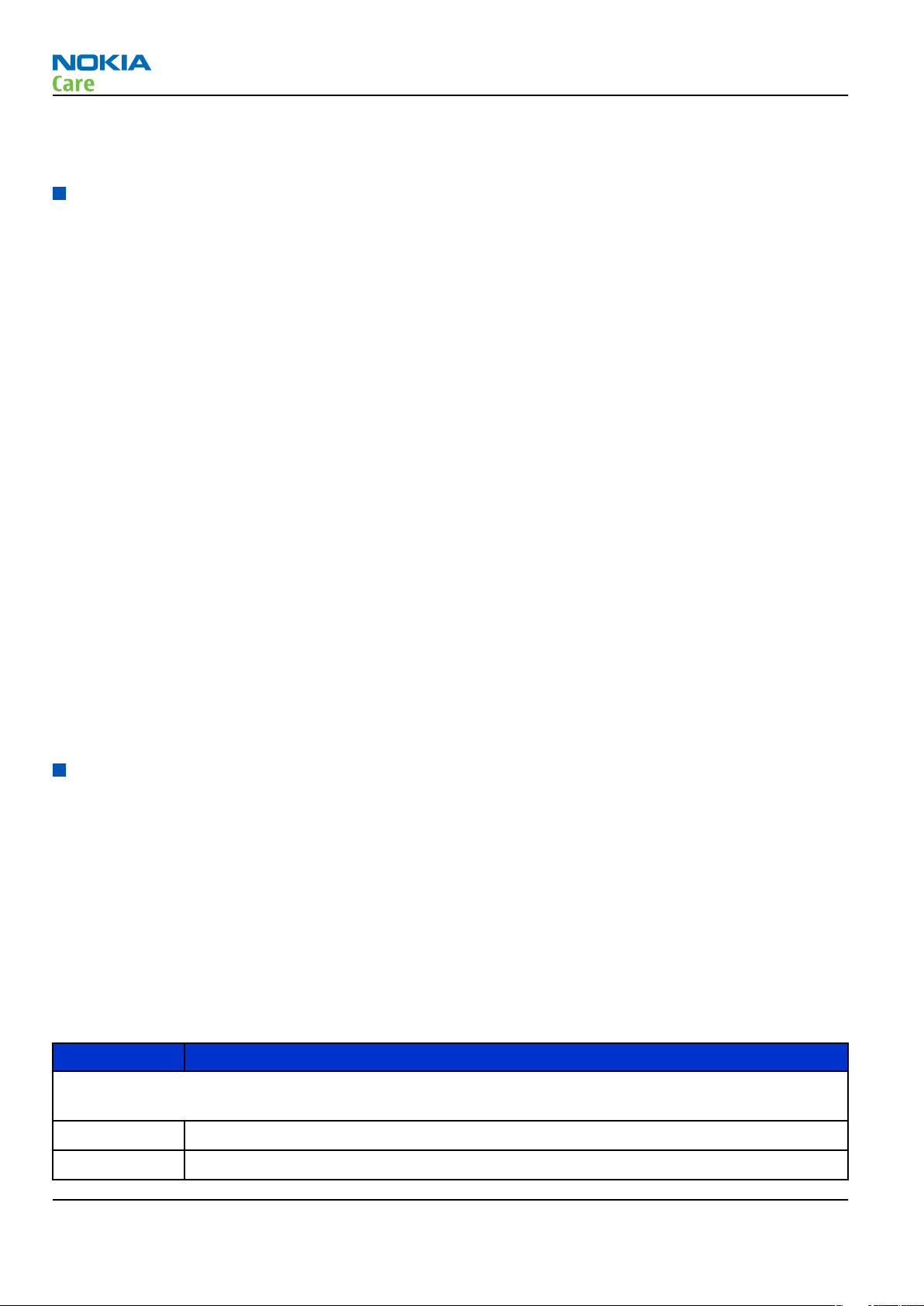
FS-67 Flash adapter
• FS-67 is equipped with a clip interlock system
• provides standardised interface towards Control Unit
• provides RF connection using coupler
• multiplexing between USB and FBUS media, controlled by VUSB
Note: FS-67 must not be used for EM-calibration.
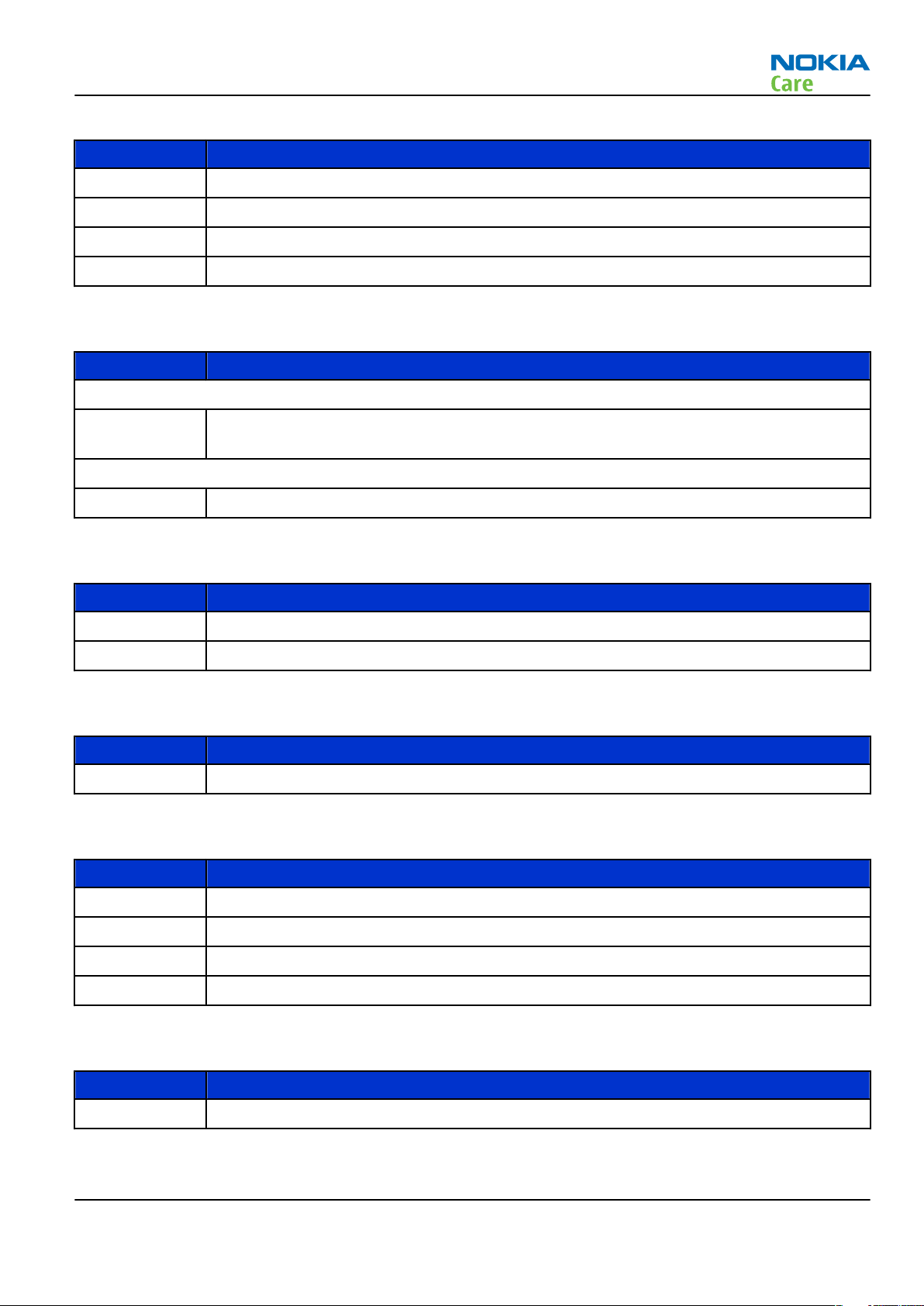
MJ-149 Module jig MJ-149 is meant for component level troubleshooting.
The jig includes an RF interface for GSM, WCDMA and Bluetooth. In
addition, it has the following features:
• Provides mechanical interface with the engine module
• Provides galvanic connection to all needed test pads in module
• Multiplexing between USB and FBUS media, controlled by Vusb
• MMC interface
• Duplicated SIM connector
• Connector for control unit
• Access for AV- and USB connectors
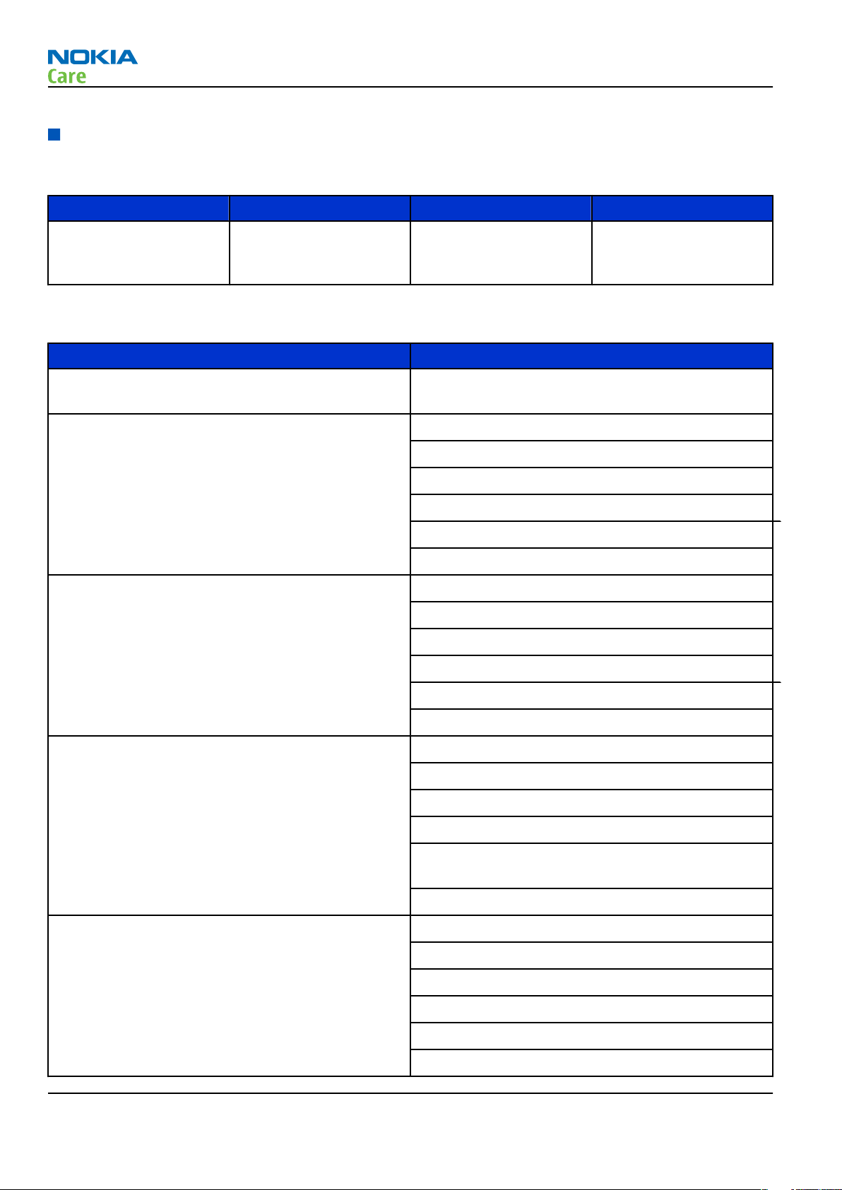
RJ-227 Rework jig
RJ-227 is a rework jig used when servicing the BTHFM module (D6000).
It is used together with the ST-70 rework stencil.
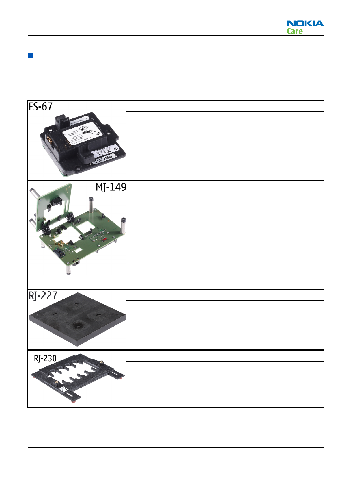
RJ-230 Soldering jig RJ-230 is a soldering jig used for soldering and as a rework jig for the
engine module.
Issue 1 COMPANY CONFIDENTIAL Page 2 –5
Copyright © 2008 Nokia. All rights reserved.
Page 28
RM-325
Service Devices and Service Concepts
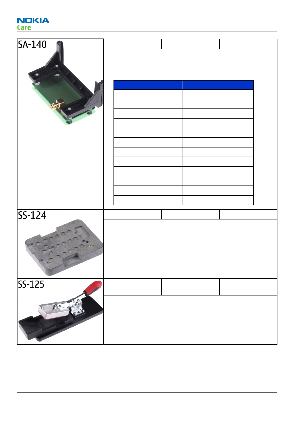
SA-140 RF coupler SA-140 is an RF coupler for GSM and WCDMA RF testing. It is used
together with the product-specific flash adapter.
The following table shows attenuations from the antenna pads of the
mobile terminal to the SMA connectors of SA-140:
•
GSM850 TX -5,6 dB
GSM850 RX -5,5 dB
GSM900 TX -5,2 dB
GSM900 RX -3,6 dB
GSM1800 TX -2,0 dB
GSM1800 RX -2,1 dB
GSM1900 TX -2,2 dB
GSM1900 RX -2,7 dB
WCDMA band V TX -5,6 dB
WCDMA band V RX -5,5 dB
WCDMA band I TX -2,6 dB
WCDMA band I RX -4,4 dB
SS-124 Domesheet tool The purpose of the domesheet tool SS-124 is to support the placement
of a domesheet on the PWB.
Frequency Att. (dB)
SS-125 Display window
compression tool
The display window compression tool SS-125 is used to support the
placement of the display window by applying an even pressure.
Page 2 –6 COMPANY CONFIDENTIAL Issue 1
Copyright © 2008 Nokia. All rights reserved.
Page 29
RM-325
Service Devices and Service Concepts
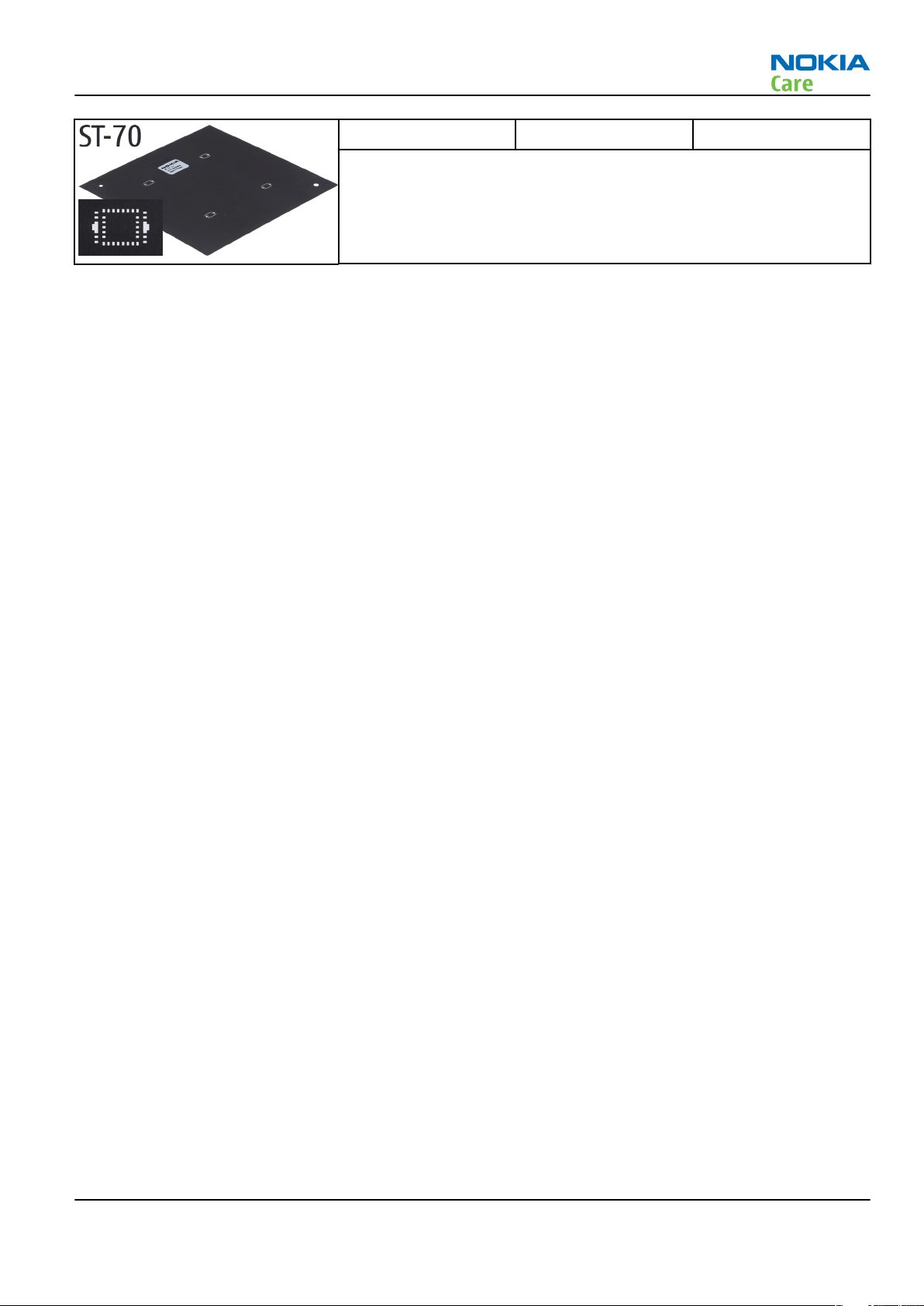
ST-70 Rework stencil ST-70 rework stencil is used with RJ-227 rework jig to service the
BTHFM module (D6000).
General devices
The table below gives a short overview of service devices that can be used for testing, error analysis, and
repair of product RM-325. For the correct use of the service devices, and the best effort of workbench setup,
please refer to various concepts.
Issue 1 COMPANY CONFIDENTIAL Page 2 –7
Copyright © 2008 Nokia. All rights reserved.
Page 30
RM-325
Service Devices and Service Concepts
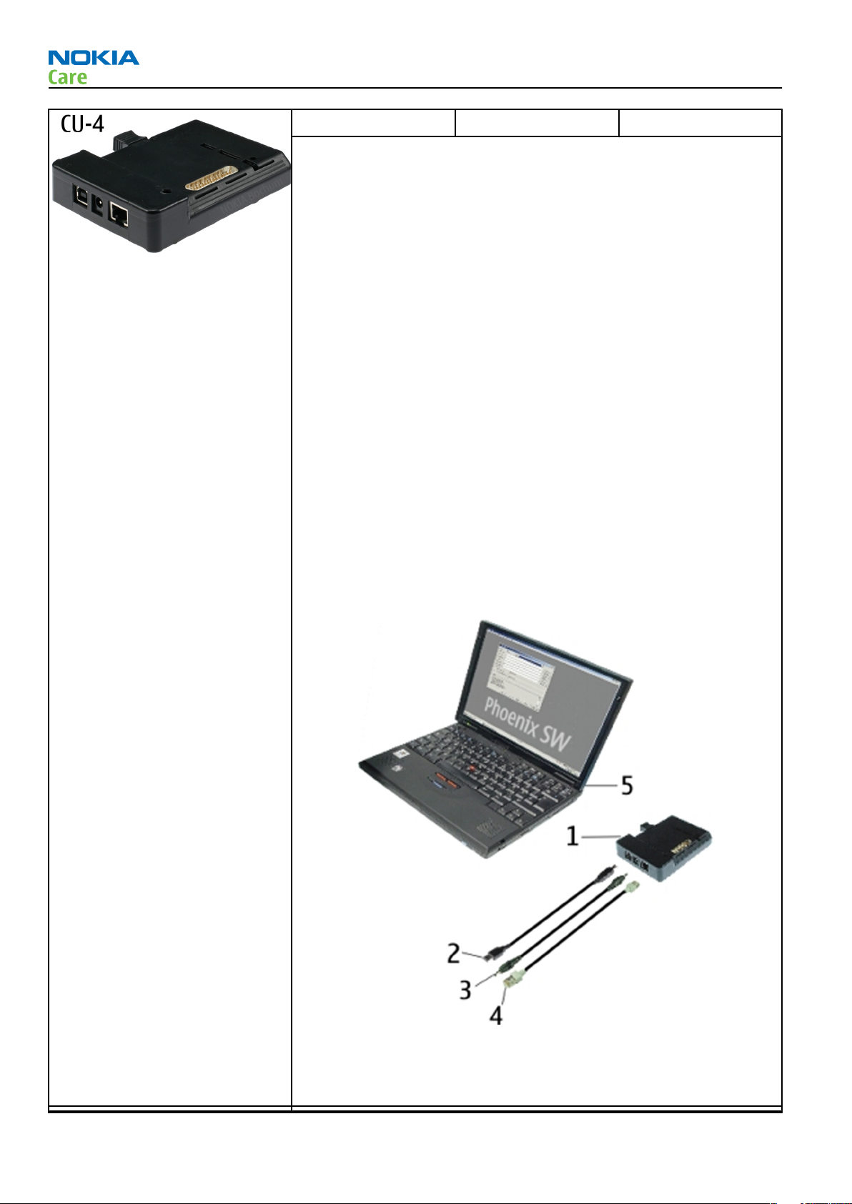
CU-4 Control unit CU-4 is a general service tool used with a module jig and/or a flash
adapter. It requires an external 12 V power supply.
The unit has the following features:
• software controlled via USB
• EM calibration function
• Forwards FBUS/Flashbus traffic to/from terminal
• Forwards USB traffic to/from terminal
• software controlled BSI values
• regulated VBATT voltage
• 2 x USB2.0 connector (Hub)
• FBUS and USB connections supported
When using CU-4, note the special order of connecting cables and
other service equipment:
Instructions
1 Connect a service tool (jig, flash adapter) to CU-4.
2 Connect CU-4 to your PC with a USB cable.
3 Connect supply voltage (12 V)
4 Connect an FBUS cable (if necessary).
5 Start Phoenix service software.
Note: Phoenix enables CU-4 regulators via USB when it is
started.
Reconnecting the power supply requires a Phoenix restart.
Page 2 –8 COMPANY CONFIDENTIAL Issue 1
Copyright © 2008 Nokia. All rights reserved.
Page 31

RM-325
Service Devices and Service Concepts
FLS-5 Flash device FLS-5 is a dongle and flash device incorporated into one package,
developed specifically for POS use.
Note: FLS-5 can be used as an alternative to PKD-1.
FPS-10 Flash prommer FPS-10 interfaces with:
• PC
• Control unit
• Flash adapter
• Smart card
FPS-10 flash prommer features:
• Flash functionality for BB5 and DCT-4 terminals
• Smart Card reader for SX-2 or SX-4
• USB traffic forwarding
• USB to FBUS/Flashbus conversion
• LAN to FBUS/Flashbus and USB conversion
• Vusb output switchable by PC command
FPS-10 sales package includes:
• FPS-10 prommer
• Power Supply with 5 country specific cords
• USB cable
Note: FPS-21 is substitute FPS-10 if FPS-10 has not been set
up.
JBT-9 Bluetooth test and
interface box (sales
package)
The JBT-9 test box is a generic service device used to perform
Bluetooth bit error rate (BER) testing, and establishing cordless FBUS
connection via Bluetooth. An ACP-8x charger is needed for BER testing
and an AXS-4 cable in case of cordless interface usage testing .
Sales package includes:
• JBT-9 test box
• Installation and warranty information
Issue 1 COMPANY CONFIDENTIAL Page 2 –9
Copyright © 2008 Nokia. All rights reserved.
Page 32

RM-325
Service Devices and Service Concepts
JXS-1 RF shield box Because the WCDMA network disturbs the RX side testing of the WCDMA
phone and the Tx signal of the WCDMA phone can severely disturb the
WCDMA network, a shield box is needed in all testing, tuning and fault
finding which requires WCDMA RF signal.
The shield box is not an active device, it contains only passive filtering
components for RF attenuation.
PK-1 Software protection
key
PK-1 is a hardware protection key with a USB interface. It has the same
functionality as the PKD-1 series dongle.
PK-1 is meant for use with a PC that does not have a series interface.
To use this USB dongle for security service functions please register
the dongle in the same way as the PKD-1 series dongle.
PKD-1 SW security device
SW security device is a piece of hardware enabling the use of the
service software when connected to the parallel (LPT) port of the PC.
Without the device, it is not possible to use the service software.
Printer or any such device can be connected to the PC through the
device if needed.
RJ-104 Rework jig RJ-104 is a rework jig used when servicing the BTHFM module. It is
used together with rework stencil ST-37.
RJ-114 Rework jig RJ-114 is a rework jig used with ST-41.
Page 2 –10 COMPANY CONFIDENTIAL Issue 1
Copyright © 2008 Nokia. All rights reserved.
Page 33

RM-325
Service Devices and Service Concepts
RJ-57 Rework jig RJ-57 is a rework jig used with ST-22.
RJ-93 Rework jig RJ-93 is used as a rework jig for the engine module.
This stencil takes the front end module (FEM) or power amplifier (PA)
module for spreading the soldering paste to the component. Must be
used together with the ST-40 stencil.
SPS-1 Soldering Paste
Spreader
The SPS-1 allows spreading of solder to the LGA components pads over
the rework stencils.
SRT-6 Opening tool SRT-6 is used to open phone covers.
Issue 1 COMPANY CONFIDENTIAL Page 2 –11
Copyright © 2008 Nokia. All rights reserved.
Page 34

RM-325
Service Devices and Service Concepts
SS-46 Interface adapter SS-46 acts as an interface adapter between the flash adapter and
FPS-10.
SS-62 Generic flash adapter
base for BB5
• generic base for flash adapters and couplers
• SS-62 equipped with a clip interlock system
• provides standardised interface towards Control Unit
• provides RF connection using galvanic connector or coupler
• multiplexing between USB and FBUS media, controlled by VUSB
ST-37 BTHFM rework stencil ST-37 stencil is used with RJ-104 BTHFM rework jig.
ST-40 Rework stencil ST-40 is a rework stencil and used with RJ-93.
ST-41 Rework stencil ST-41 is a rework stencil used with rework jig RJ-114.
ST-44 Rework stencil ST-44 is a rework stencil used with rework jig RJ-57.
Page 2 –12 COMPANY CONFIDENTIAL Issue 1
Copyright © 2008 Nokia. All rights reserved.
Page 35
RM-325
Service Devices and Service Concepts
SX-4 Smart card SX-4 is a BB5 security device used to protect critical features in tuning
and testing.
SX-4 is also needed together with FPS-10 when DCT-4 phones are
flashed.
Cables
The table below gives a short overview of service devices that can be used for testing, error analysis, and
repair of product RM-325. For the correct use of the service devices, and the best effort of workbench setup,
please refer to various concepts.
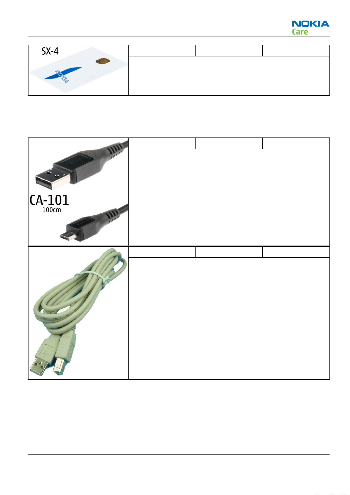
CA-101 Micro USB cable The CA-101 is a USB-to-microUSB data cable that allows connections
between the PC and the phone.
CA-31D USB cable The CA-31D USB cable is used to connect FPS-10 or FPS-11 to a PC. It is
included in the FPS-10 and FPS-11 sales packages.
Issue 1 COMPANY CONFIDENTIAL Page 2 –13
Copyright © 2008 Nokia. All rights reserved.
Page 36

RM-325
Service Devices and Service Concepts
CA-35S Power cable CA-35S is a power cable for connecting, for example, the FPS-10 flash
prommer to the Point-Of-Sales (POS) flash adapter.
PCS-1 Power cable The PCS-1 power cable (DC) is used with a docking station, a module
jig or a control unit to supply a controlled voltage.
XCS-4 Modular cable XCS-4 is a shielded (one specially shielded conductor) modular cable
for flashing and service purposes.
Page 2 –14 COMPANY CONFIDENTIAL Issue 1
Copyright © 2008 Nokia. All rights reserved.
Page 37

RM-325
Service Devices and Service Concepts
Service concepts
POS (Point of Sale) flash concept
XRS-6 RF cable The RF cable is used to connect, for example, a module repair jig to
the RF measurement equipment.
SMA to N-Connector approximately 610 mm.
Attenuation for:
• GSM850/900: 0.3+-0.1 dB
• GSM1800/1900: 0.5+-0.1 dB
• WCDMA/WLAN: 0.6+-0.1dB
Figure 2 POS flash concept
Type Description
Product specific tools
BL-4CT Battery
Other tools
FLS-5 POS flash dongle
PC with Phoenix service software
Cables
Issue 1 COMPANY CONFIDENTIAL Page 2 –15
Copyright © 2008 Nokia. All rights reserved.
Page 38

Type Description
DKE-2 USB connectivity cable
Flash concept with FPS-10
RM-325
Service Devices and Service Concepts
Figure 3 Basic flash concept with FPS-10
Type Description
Product specific devices
FS-67 Flash adapter
Other devices
FPS-10 Flash prommer box
PKD-1/PK-1 SW security device
SS-46 Interface adapter
PC with Phoenix service software
Cables
XCS-4 Modular cable
CA-35S Power cable
USB cable
Page 2 –16 COMPANY CONFIDENTIAL Issue 1
Copyright © 2008 Nokia. All rights reserved.
Page 39
RM-325
Service Devices and Service Concepts
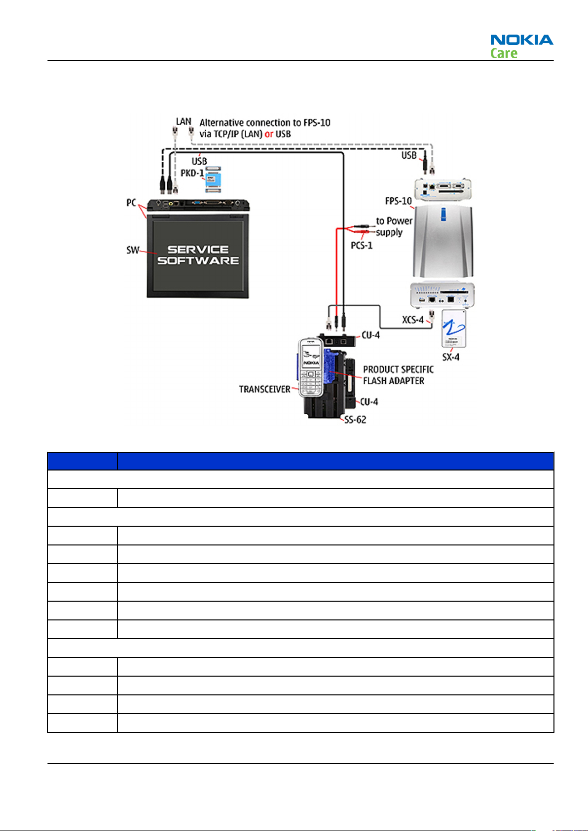
CU-4 flash concept with FPS-10
Figure 4 CU-4 flash concept with FPS-10
Type Description
Product specific devices
FS-67 Flash adapter
Other devices
CU-4 Control unit
FPS-10 Flash prommer box
PKD-1/PK-1 SW security device
SS-62 Flash adapter base
SX-4 Smart card
PC with Phoenix service software
Cables
PCS-1 Power cable
XCS-4 Modular cable
Standard USB cable
USB cable
Issue 1 COMPANY CONFIDENTIAL Page 2 –17
Copyright © 2008 Nokia. All rights reserved.
Page 40

Module jig service concept
RM-325
Service Devices and Service Concepts
Figure 5 Module jig service concept
Type Description
Phone specific devices
MJ-149 Module jig
Other devices
CU-4 Control unit
FPS-10 Flash prommer box
PK-1 SW security device
SX-4 Smart card
PC with VPOS and Phoenix service software
Measurement equipment
Cables
PCS-1 DC power cable
XCS-4 Modular cable
XRF-1 RF cable
USB cable
Page 2 –18 COMPANY CONFIDENTIAL Issue 1
Copyright © 2008 Nokia. All rights reserved.
Page 41
RM-325
Service Devices and Service Concepts
Type Description
GPIB control cable
RF testing concept with RF coupler
Figure 6 RF testing concept with RF coupler
Type Description
Product specific devices
FS-67 Flash adapter
SA-140 RF coupler
Other devices
CU-4 Control unit
SX-4 Smart card
FPS-10 Flash prommer box
PKD-1/PK-1 SW security device
SS-62 Flash adapter base
Measurement equipment
PC with Phoenix service software
Cables
PCS-1 Power cable
Issue 1 COMPANY CONFIDENTIAL Page 2 –19
Copyright © 2008 Nokia. All rights reserved.
Page 42

Type Description
XCS-4 Modular cable
XRS-6 RF cable
GPIB control cable
USB cable
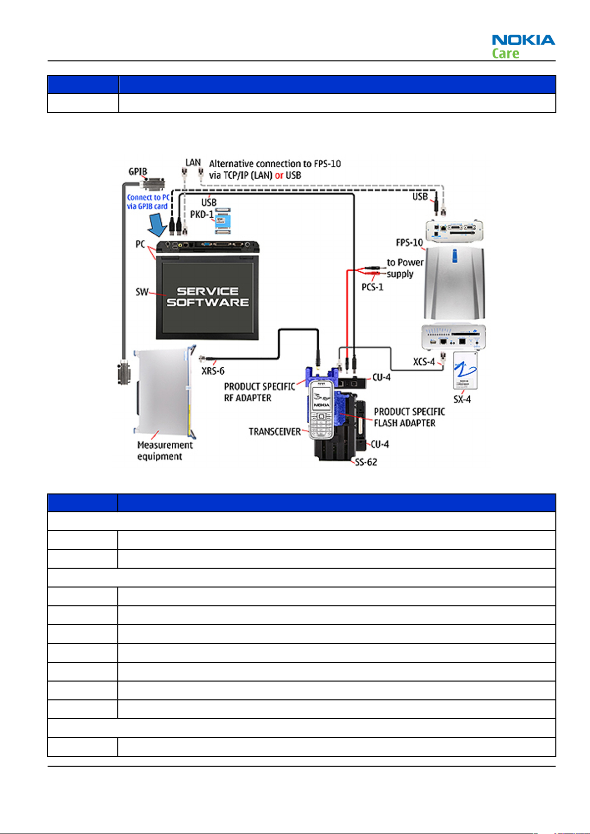
Service concept for RF testing and RF/BB tuning
RM-325
Service Devices and Service Concepts
Figure 7 Service concept for RF testing and RF/BB tuning
Type Description
Product specific devices
MJ-149 Module jig
Other devices
CU-4 Control unit
PK-1 SW security device
SX-4 Smart card
Measurement equipment
Smart card reader
PC with Phoenix service software
Page 2 –20 COMPANY CONFIDENTIAL Issue 1
Copyright © 2008 Nokia. All rights reserved.
Page 43

RM-325
Service Devices and Service Concepts
Type Description
Cables
DAU-9S MBUS cable
PCS-1 DC power cable
XRS-6 RF cable
GPIB control cable
USB cable
Issue 1 COMPANY CONFIDENTIAL Page 2 –21
Copyright © 2008 Nokia. All rights reserved.
Page 44

RM-325
Service Devices and Service Concepts
(This page left intentionally blank.)
Page 2 –22 COMPANY CONFIDENTIAL Issue 1
Copyright © 2008 Nokia. All rights reserved.
Page 45

Nokia Customer Care
3 — BB Troubleshooting and
Manual Tuning Guide
Issue 1 COMPANY CONFIDENTIAL Page 3 –1
Copyright © 2008 Nokia. All rights reserved.
Page 46

RM-325
BB Troubleshooting and Manual Tuning Guide
(This page left intentionally blank.)
Page 3 –2 COMPANY CONFIDENTIAL Issue 1
Copyright © 2008 Nokia. All rights reserved.
Page 47

RM-325
BB Troubleshooting and Manual Tuning Guide
Table of Contents
Baseband self tests in Phoenix .............................................................................................................................3–5
Power and charging troubleshooting..................................................................................................................3–7
Dead or jammed device troubleshooting.......................................................................................................3–7
General power checking...................................................................................................................................3–9
DC charging troubleshooting ........................................................................................................................ 3–10
USB charging troubleshooting...................................................................................................................... 3–11
Interface troubleshooting .................................................................................................................................. 3–12
Flash programming fault troubleshooting.................................................................................................. 3–12
Combo memory troubleshooting ................................................................................................................. 3–15
SD card troubleshooting................................................................................................................................ 3–15
USB interface troubleshooting...................................................................................................................... 3–17
SIM card troubleshooting .............................................................................................................................. 3–18
User interface troubleshooting.......................................................................................................................... 3–19
Keypad and side key troubleshooting ......................................................................................................... 3–19
Power key troubleshooting........................................................................................................................... 3–20
Accelerometer self test troubleshooting ..................................................................................................... 3–21
Electromagnet ................................................................................................................................................ 3–22
Display module troubleshooting.................................................................................................................. 3–23
Keyboard backlight troubleshooting ........................................................................................................... 3–24
Keyboard backlight LED troubleshooting .................................................................................................... 3–26
Ambient light sensor (ALS) troubleshooting............................................................................................... 3–26
Camera module troubleshooting....................................................................................................................... 3–30
Introduction to camera troubleshooting .................................................................................................... 3–30
Main (back) camera troubleshooting........................................................................................................... 3–30
Taking and evaluating test pictures with main camera ....................................................................... 3–30
Main camera troubleshooting ................................................................................................................. 3–31
Main camera bad image quality troubleshooting ................................................................................. 3–31
Main camera viewfinder troubleshooting.............................................................................................. 3–32
Main camera hardware failure message troubleshooting.................................................................... 3–34
Main camera hardware troubleshooting................................................................................................ 3–35
LED camera flash troubleshooting .......................................................................................................... 3–36
Secondary (front) camera troubleshooting................................................................................................. 3–36
Evaluating videocall picture quality from secondary camera .............................................................. 3–36
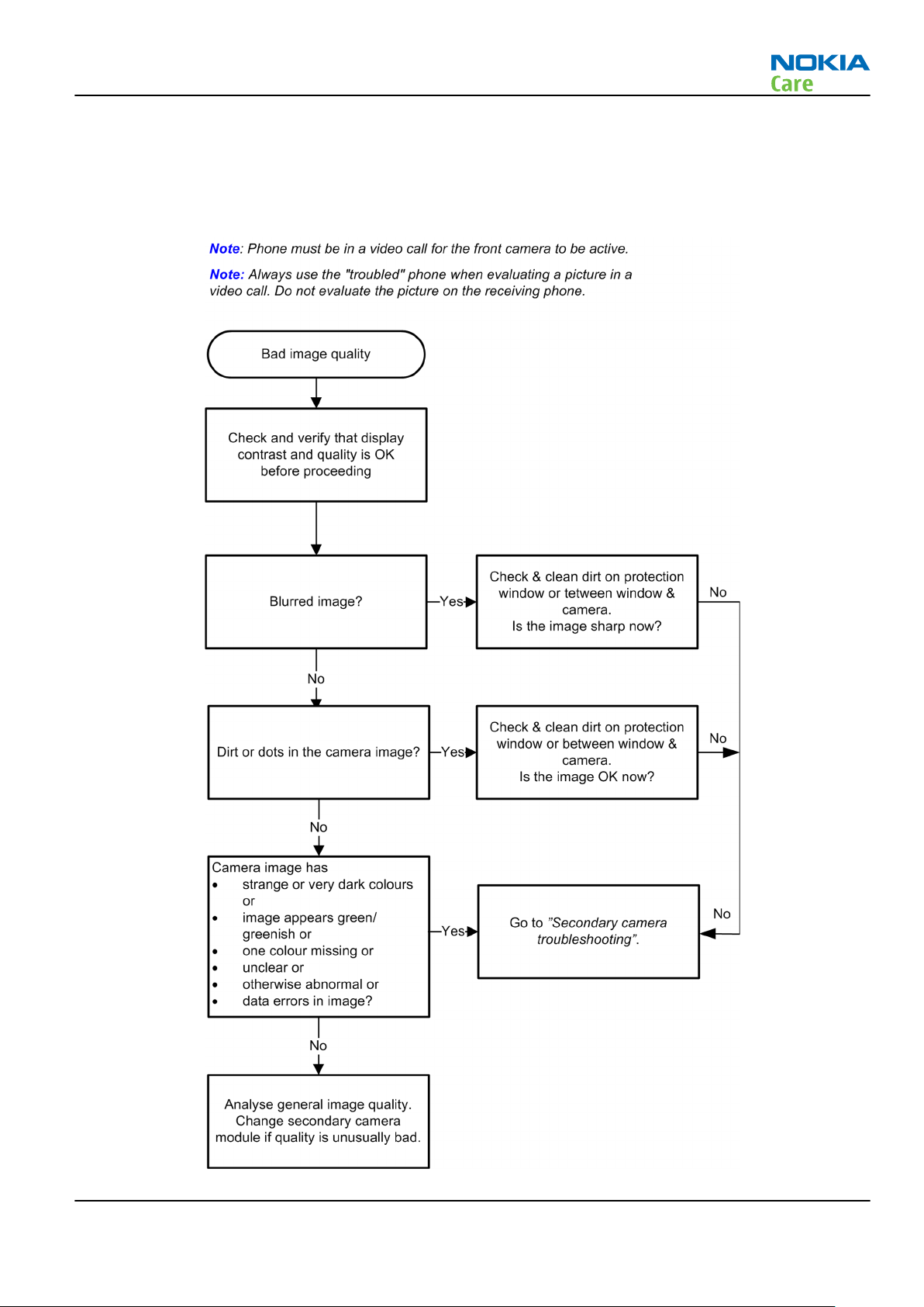
Secondary camera bad image quality troubleshooting........................................................................ 3–37
Secondary camera troubleshooting........................................................................................................ 3–38
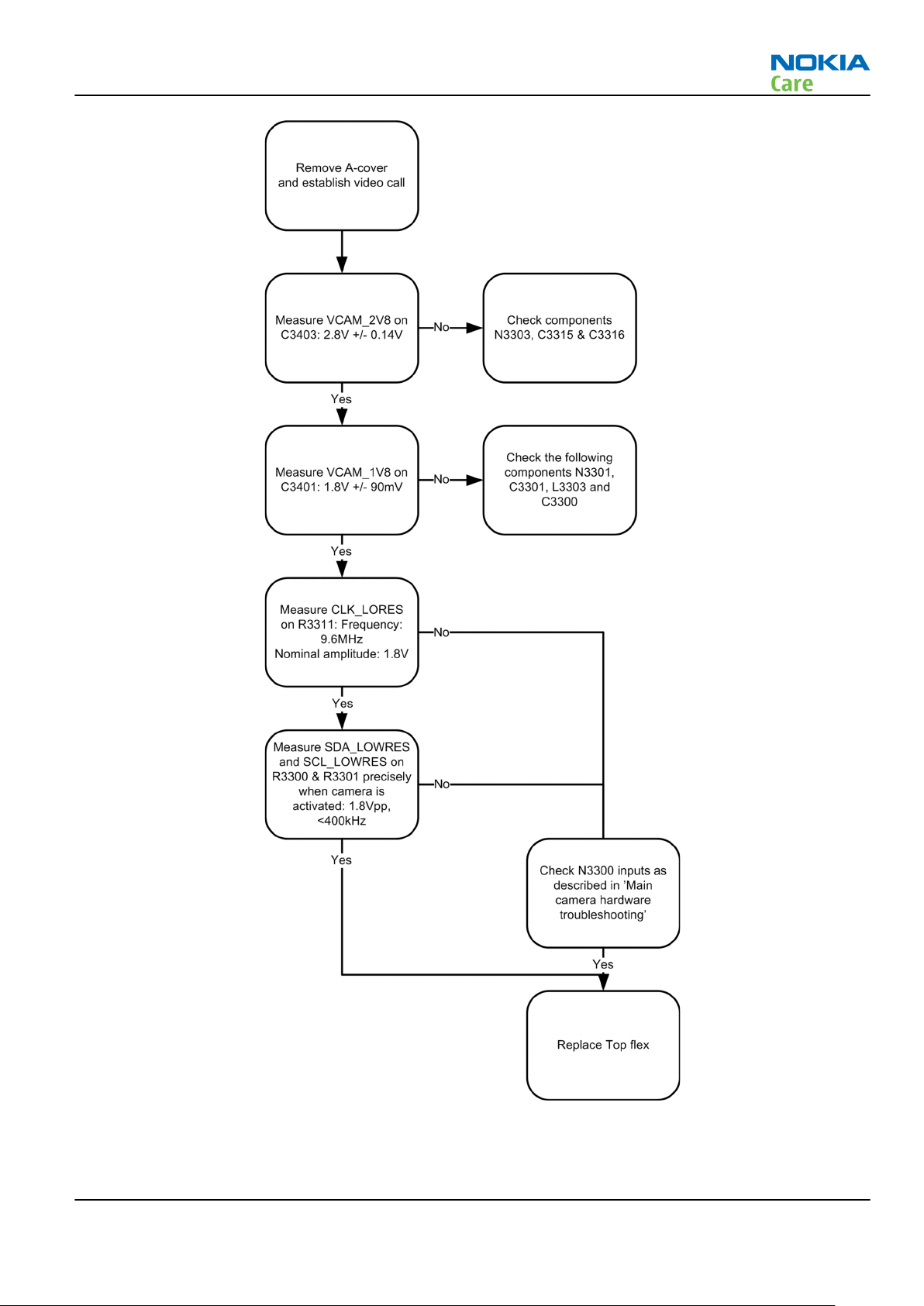
Secondary camera hardware troubleshooting ...................................................................................... 3–38
Audio troubleshooting........................................................................................................................................ 3–40
Audio troubleshooting test instructions...................................................................................................... 3–40
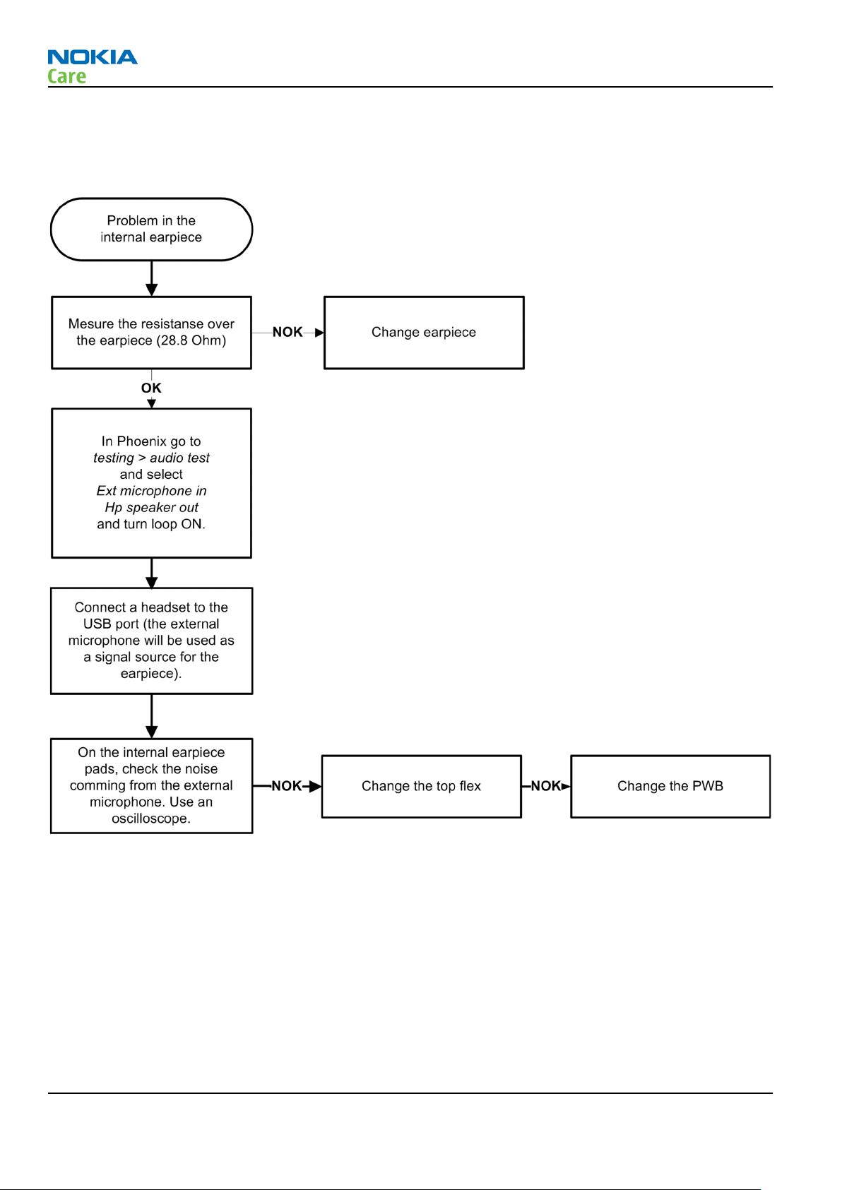
Internal earpiece troubleshooting ............................................................................................................... 3–44
Internal microphone troubleshooting......................................................................................................... 3–44
Internal handsfree (IHF) troubleshooting.................................................................................................... 3–45
External earpiece troubleshooting............................................................................................................... 3–46
External microphone troubleshooting......................................................................................................... 3–47
Vibra troubleshooting.................................................................................................................................... 3–48
Bluetooth troubleshooting................................................................................................................................. 3–50
Baseband manual tuning guide......................................................................................................................... 3–50
Certificate restoring for BB5 products.......................................................................................................... 3–50
Energy management calibration.................................................................................................................. 3–56
Issue 1 COMPANY CONFIDENTIAL Page 3 –3
Copyright © 2008 Nokia. All rights reserved.
Page 48

RM-325
BB Troubleshooting and Manual Tuning Guide
List of Tables
Table 8 Calibration value limits ......................................................................................................................... 3–56
List of Figures
Figure 8 Flashing pic 1. Take single trig measurement for the rise of the BSI signal.................................. 3–13
Figure 9 Flashing pic 2. Take single trig measurement for the rise of the BSI signal.................................. 3–14
Figure 10 Ambient light sensor calibration window....................................................................................... 3–27
Figure 11 Display test.......................................................................................................................................... 3–27
Figure 12 ADC readings....................................................................................................................................... 3–28
Figure 13 Single-ended output waveform of the Ext_in_HP_out measurement when earpiece is
connected. ................................................................................................................................................. 3–42
Figure 14 Differential output waveform of the Ext_in_IHF_out out loop measurement when speaker is
connected. ................................................................................................................................................. 3–42
Figure 15 Single-ended output waveform of the HP_in_Ext_out loop when microphone is connected....
3–43
Figure 16 Troubleshooting diagram: Bluetooth .............................................................................................. 3–50
Page 3 –4 COMPANY CONFIDENTIAL Issue 1
Copyright © 2008 Nokia. All rights reserved.
Page 49

RM-325
BB Troubleshooting and Manual Tuning Guide
Baseband self tests in Phoenix
Context
Always start the troubleshooting procedure by running the Phoenix self tests. If a test fails, please follow the
diagram below.
If the phone is dead and you cannot perform the self tests, go to
Dead or jammed device troubleshooting.
Issue 1 COMPANY CONFIDENTIAL Page 3 –5
Copyright © 2008 Nokia. All rights reserved.
Page 50

Troubleshooting flow
RM-325
BB Troubleshooting and Manual Tuning Guide
Page 3 –6 COMPANY CONFIDENTIAL Issue 1
Copyright © 2008 Nokia. All rights reserved.
Page 51

RM-325
BB Troubleshooting and Manual Tuning Guide
Power and charging troubleshooting
Dead or jammed device troubleshooting
Troubleshooting flow
Issue 1 COMPANY CONFIDENTIAL Page 3 –7
Copyright © 2008 Nokia. All rights reserved.
Page 52

Troubleshooting flow
RM-325
BB Troubleshooting and Manual Tuning Guide
Page 3 –8 COMPANY CONFIDENTIAL Issue 1
Copyright © 2008 Nokia. All rights reserved.
Page 53

RM-325
BB Troubleshooting and Manual Tuning Guide
General power checking
Check the following voltages:
Signal
Rename
VIO AVILMA ON ON 1.82 Memory, I/Os,
VBACK AVILMA ON ON 2.50 Back-up
VSIM1 AVILMA ON ON 1.8/3.0 SIM card
VSIM2 AVILMA OFF OFF 1.8/3.0
VDRAM AVILMA ON ON 1.82 SDRAM
VAUX AVILMA OFF OFF 2.78 Accelerometer,
VANA AVILMA OFF OFF 2.50
VR1 AVILMA OFF ON 2.50 Crystal
VRFC AVILMA OFF ON 1.80 RAP3G
VRCP1 AVILMA 4.75 To RF parts RF active
VREF AVILMA ON ON 1.35 RF reference
Regulator Sleep Idle Nominal
voltage
Main user Notes
Display, USB
battery
hall sensor, ALS
RF section
oscillators
converters
VCORE BETTY ON ON 1.05
(sleep)
1.35
VOUT BETTY OFF OFF 2.50 Accessory
VCAM_2V8 LP3987ITLX-2.
85/N3303
VCAM_1V8 LM3677TLX-1.
82/N3301
VCAM_1V3 LP5952TLX-1.
3/N3302
VIBRA+ LP3985ITLX-3.
0/N2100
VSD LP3929TMEX-
AACQ/N4802
LIGHT LP5521TMX/
N2401
OFF OFF 2.85 Camera Disabled in
OFF OFF 1.80 Camera Disabled in
OFF OFF 1.30 Camera Disabled in
ON ON 3.00 Vibra Only turned off
OFF OFF 2.85 SD card Disabled in
OFF OFF 3.6
2.1
RAP3G digital
connected
sleep
sleep
sleep
in "Power off"
mode
sleep
Key light, top
light
alive light
Issue 1 COMPANY CONFIDENTIAL Page 3 –9
Copyright © 2008 Nokia. All rights reserved.
Page 54

DC charging troubleshooting
Troubleshooting flow
RM-325
BB Troubleshooting and Manual Tuning Guide
Page 3 –10 COMPANY CONFIDENTIAL Issue 1
Copyright © 2008 Nokia. All rights reserved.
Page 55
RM-325
BB Troubleshooting and Manual Tuning Guide
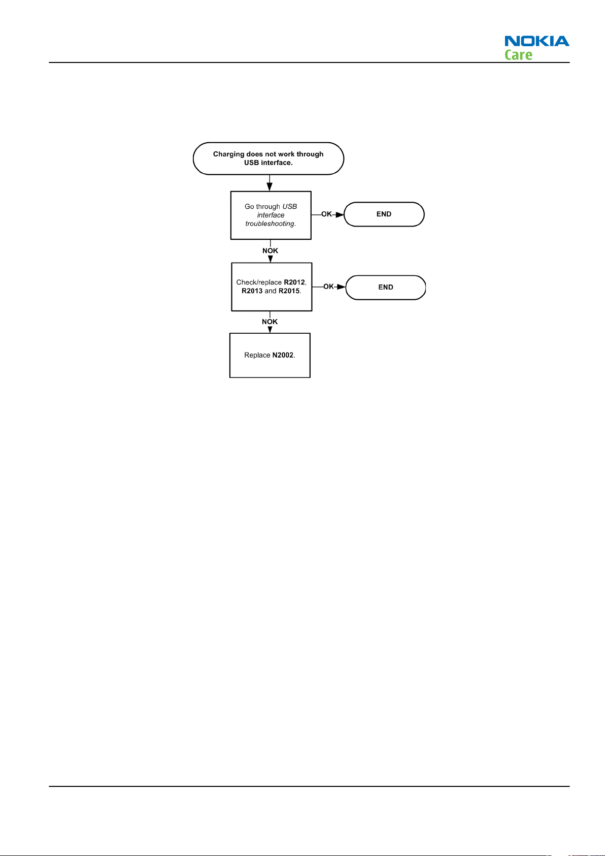
USB charging troubleshooting
Troubleshooting flow
Issue 1 COMPANY CONFIDENTIAL Page 3 –11
Copyright © 2008 Nokia. All rights reserved.
Page 56
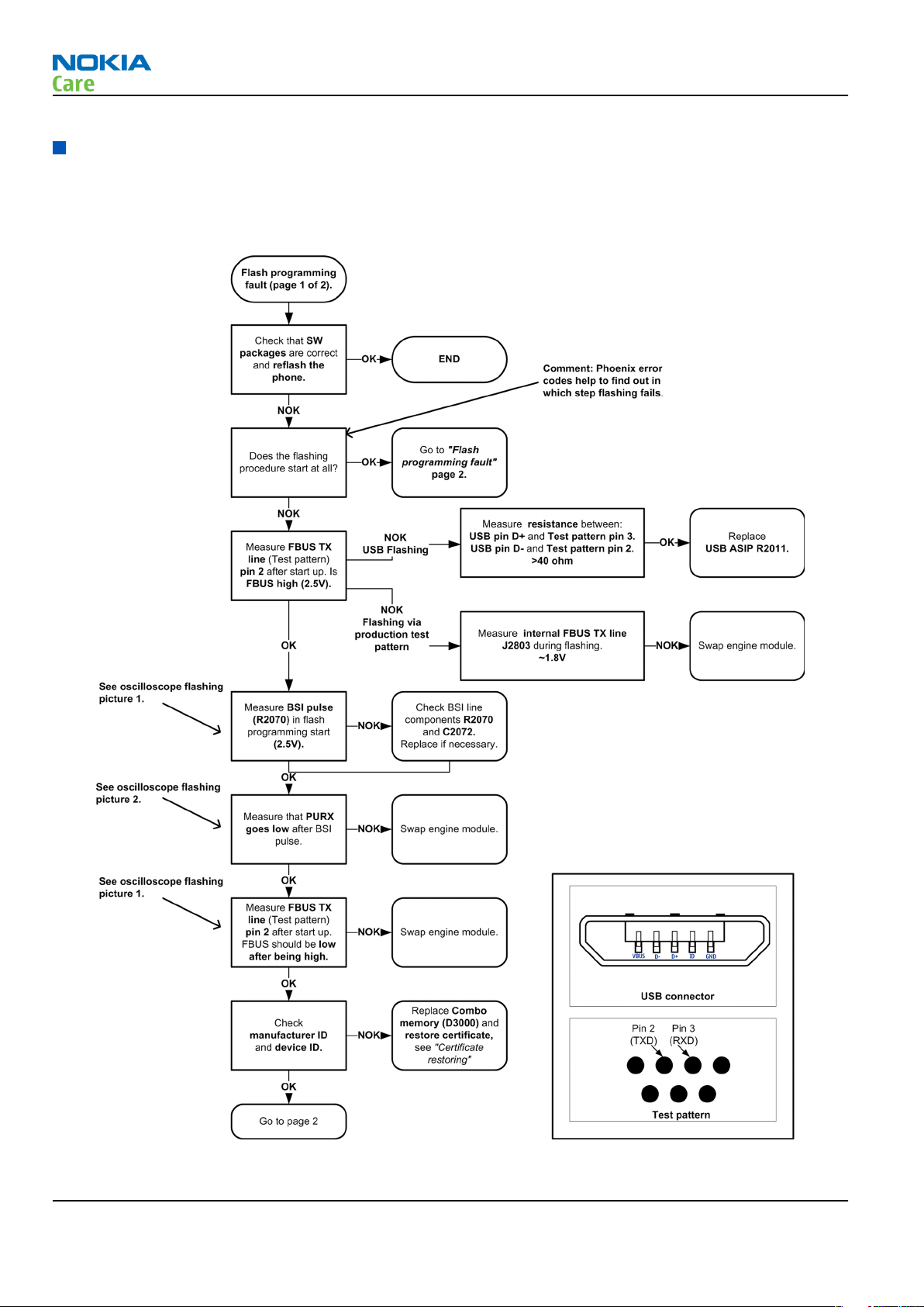
Interface troubleshooting
Flash programming fault troubleshooting
Part 1
RM-325
BB Troubleshooting and Manual Tuning Guide
Page 3 –12 COMPANY CONFIDENTIAL Issue 1
Copyright © 2008 Nokia. All rights reserved.
Page 57

RM-325
BB Troubleshooting and Manual Tuning Guide
Part 2
Figure 8 Flashing pic 1. Take single trig measurement for the rise of the BSI signal.
Issue 1 COMPANY CONFIDENTIAL Page 3 –13
Copyright © 2008 Nokia. All rights reserved.
Page 58

BB Troubleshooting and Manual Tuning Guide
Figure 9 Flashing pic 2. Take single trig measurement for the rise of the BSI signal.
RM-325
Page 3 –14 COMPANY CONFIDENTIAL Issue 1
Copyright © 2008 Nokia. All rights reserved.
Page 59

RM-325
BB Troubleshooting and Manual Tuning Guide
Combo memory troubleshooting
Troubleshooting flow
Issue 1 COMPANY CONFIDENTIAL Page 3 –15
Copyright © 2008 Nokia. All rights reserved.
Page 60
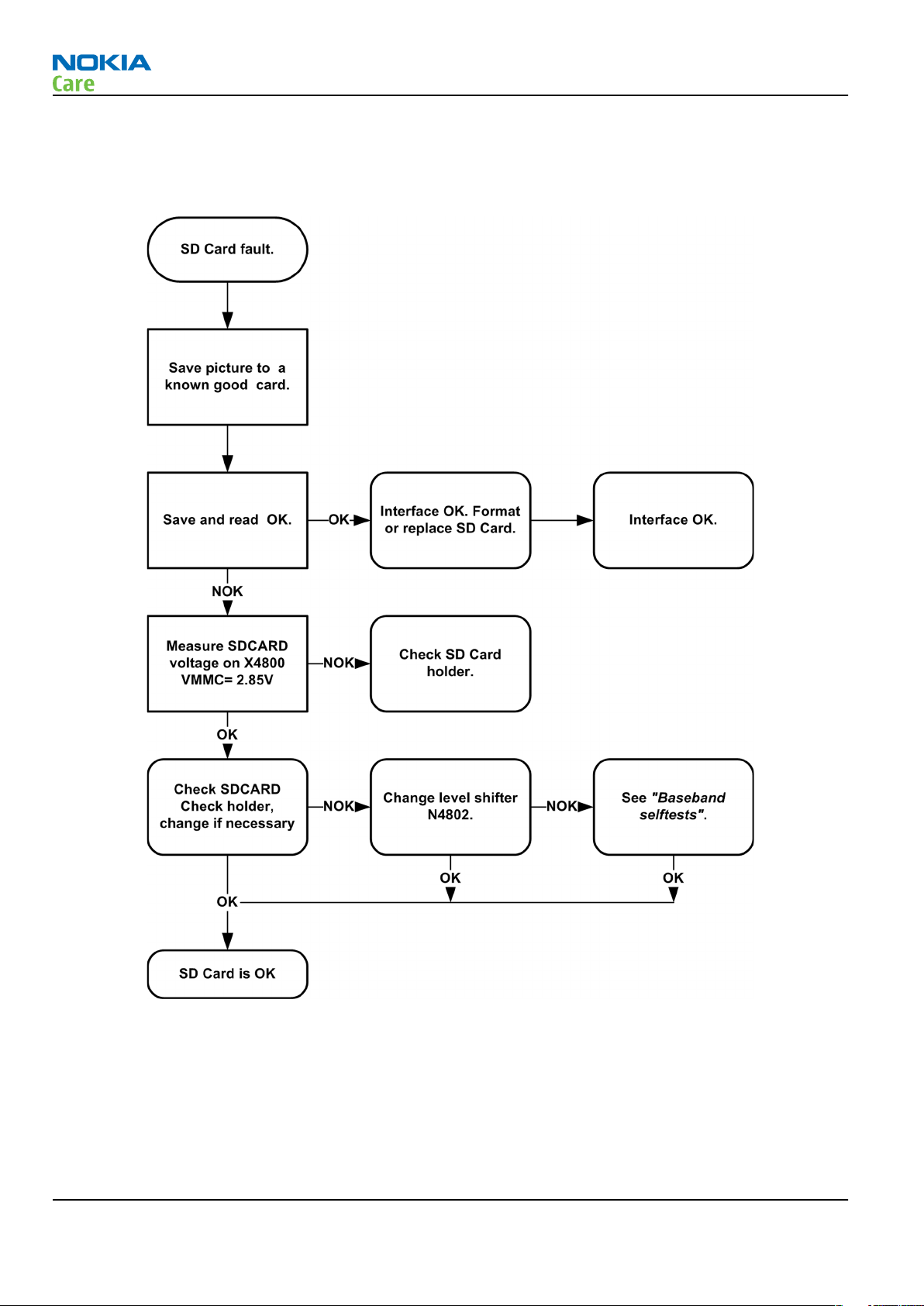
SD card troubleshooting
Troubleshooting flow
RM-325
BB Troubleshooting and Manual Tuning Guide
Page 3 –16 COMPANY CONFIDENTIAL Issue 1
Copyright © 2008 Nokia. All rights reserved.
Page 61
RM-325
BB Troubleshooting and Manual Tuning Guide
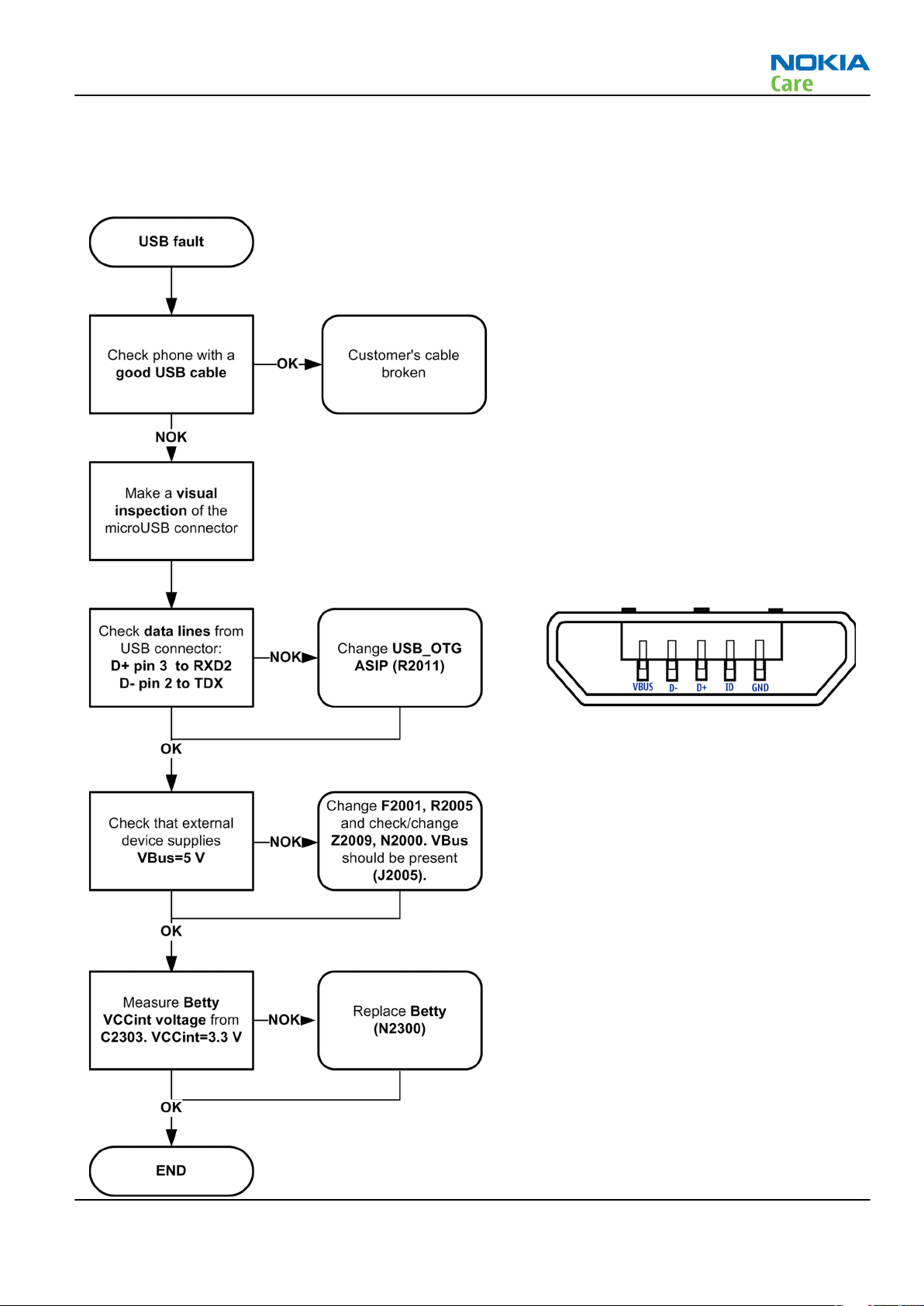
USB interface troubleshooting
Troubleshooting flow
Issue 1 COMPANY CONFIDENTIAL Page 3 –17
Copyright © 2008 Nokia. All rights reserved.
Page 62

SIM card troubleshooting
Troubleshooting flow
RM-325
BB Troubleshooting and Manual Tuning Guide
Page 3 –18 COMPANY CONFIDENTIAL Issue 1
Copyright © 2008 Nokia. All rights reserved.
Page 63

RM-325
BB Troubleshooting and Manual Tuning Guide
User interface troubleshooting
Keypad and side key troubleshooting
Context
If one or more keys are stuck, so that the key does not react when a keydome or the side key is pressed, the
failure is caused by mechanical reasons (dirt, rust, mechanical damage, etc.)
If the failure mode is not clear, start with the Keyboard test in Phoenix.
Troubleshooting flow
Issue 1 COMPANY CONFIDENTIAL Page 3 –19
Copyright © 2008 Nokia. All rights reserved.
Page 64
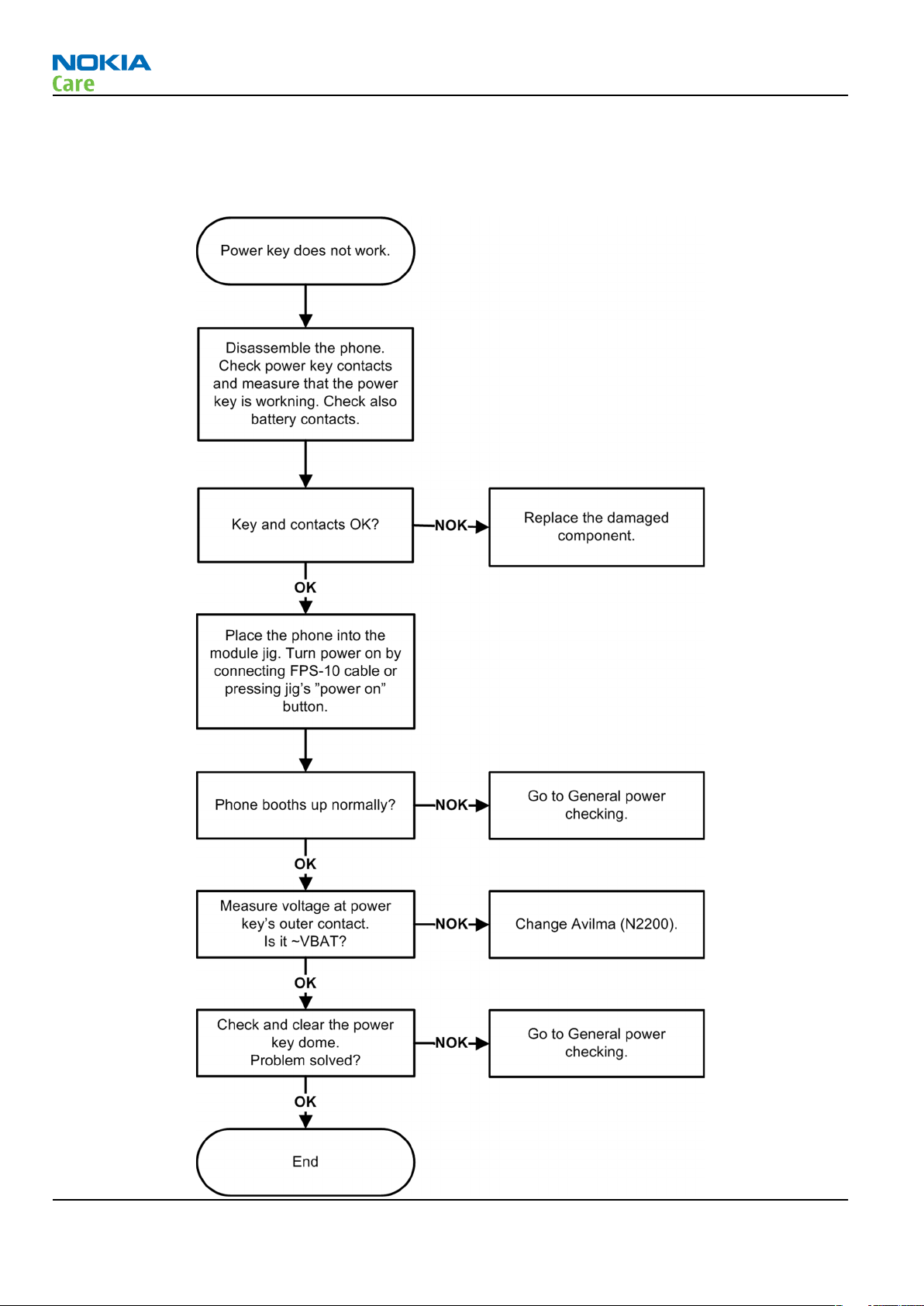
Power key troubleshooting
Troubleshooting flow
RM-325
BB Troubleshooting and Manual Tuning Guide
Page 3 –20 COMPANY CONFIDENTIAL Issue 1
Copyright © 2008 Nokia. All rights reserved.
Page 65

RM-325
BB Troubleshooting and Manual Tuning Guide
Accelerometer self test troubleshooting
Troubleshooting flow
Issue 1 COMPANY CONFIDENTIAL Page 3 –21
Copyright © 2008 Nokia. All rights reserved.
Page 66

Electromagnet
Troubleshooting flow
RM-325
BB Troubleshooting and Manual Tuning Guide
Page 3 –22 COMPANY CONFIDENTIAL Issue 1
Copyright © 2008 Nokia. All rights reserved.
Page 67

RM-325
BB Troubleshooting and Manual Tuning Guide
Electromagnet replacement
1 Remove the defective electromagnet.
2 Clean both solder pads on the engine.
3 Place the new electromagnet.
4 Solder the new electromagnet with suitable tools: solder iron in combination with under heater device.
5 Check the soldering result in a microscope.
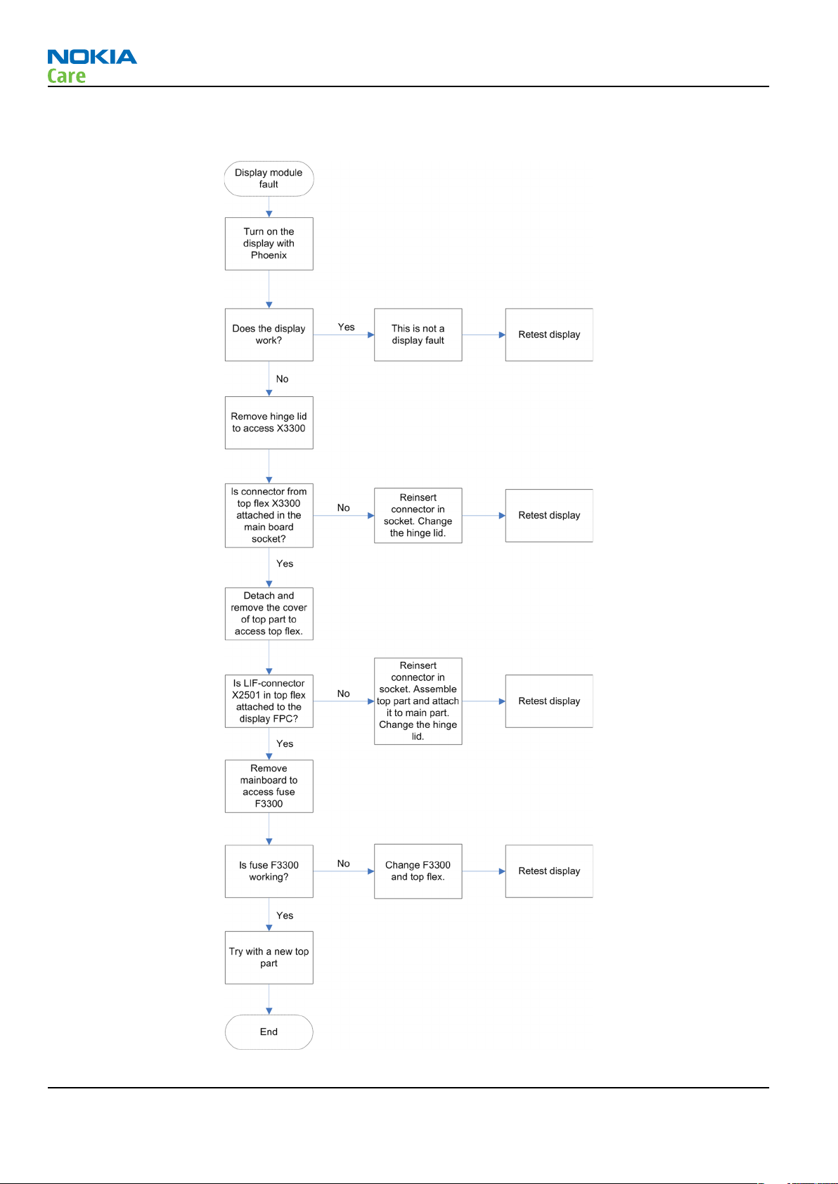
Display module troubleshooting
Context
The display module consists of two different displays, a main display and a secondary display. The state of
the displays is determined by the state of the phone.
Fold Main display Secondary display
Open On Off
Closed Off On
Use the display test tool in Phoenix to find the detailed fault mode.
Issue 1 COMPANY CONFIDENTIAL Page 3 –23
Copyright © 2008 Nokia. All rights reserved.
Page 68
Troubleshooting flow
RM-325
BB Troubleshooting and Manual Tuning Guide
Page 3 –24 COMPANY CONFIDENTIAL Issue 1
Copyright © 2008 Nokia. All rights reserved.
Page 69

RM-325
BB Troubleshooting and Manual Tuning Guide
Keyboard backlight troubleshooting
Context
Keyboard light is turned on only in dark conditions. This is controlled by the Ambient Light Sensor (ALS).
You can enable/disable ALS with the help of Phoenix service software, by turning keyboard backlight on/off.
ALS is enabled again by pressing any key on the phone.
Troubleshooting flow
Issue 1 COMPANY CONFIDENTIAL Page 3 –25
Copyright © 2008 Nokia. All rights reserved.
Page 70

Keyboard backlight LED troubleshooting
Troubleshooting flow
RM-325
BB Troubleshooting and Manual Tuning Guide
Ambient light sensor (ALS) troubleshooting
Prerequisites
Make sure that you have completed the
troubleshooting.
Keyboard backlight troubleshooting
before continuing with the ALS
Context
If ALS chip is broken replace it with Greymon ALS chip. If calibration values are lost (e.g. after replacing the
memory chip) or if the ALS chip is replaced, the calibration values in the phone memory has to be changed
to the default value: 1.
Phoenix has an ALS calibration tool for changing calibration values and it’s done following way:
1 Open Phoenix
2 Connect phone and build up connection
3 Open Tools→Ambient Light Sensor calibration window
4 Ensure that Use default values only flag is set
5 Click Write
Page 3 –26 COMPANY CONFIDENTIAL Issue 1
Copyright © 2008 Nokia. All rights reserved.
Page 71

RM-325
BB Troubleshooting and Manual Tuning Guide
Figure 10 Ambient light sensor calibration window
Figure 11 Display test
Issue 1 COMPANY CONFIDENTIAL Page 3 –27
Copyright © 2008 Nokia. All rights reserved.
Page 72

RM-325
BB Troubleshooting and Manual Tuning Guide
Figure 12 ADC readings
Page 3 –28 COMPANY CONFIDENTIAL Issue 1
Copyright © 2008 Nokia. All rights reserved.
Page 73

RM-325
BB Troubleshooting and Manual Tuning Guide
Troubleshooting flow
Issue 1 COMPANY CONFIDENTIAL Page 3 –29
Copyright © 2008 Nokia. All rights reserved.
Page 74

RM-325
BB Troubleshooting and Manual Tuning Guide
Camera module troubleshooting
Introduction to camera troubleshooting
Bad conditions often cause bad pictures. Therefore, the camera operation has to be checked in constant
conditions or by using a second, known-to-be-good Nokia device as reference. Image quality is hard to
measure quantitatively, and the difference between a good and a bad picture can be small. Some training
or experience may be needed to detect what is actually wrong.
When checking for possible errors in camera functionality, knowing what error is suspected significantly
helps the testing by narrowing down the amount of test cases. The following types of image quality problems
are common:
• Dust (black spots)
• Lack of sharpness
• Bit errors
Main (back) camera troubleshooting
Taking and evaluating test pictures with main camera
When
• Avoid bright fluorescent light, 50/60Hz electrical network or high artificial illumination levels
• If the phone is hot, let it rest for a while before taking the picture
• Make sure the optical system is clean
• Use highest possible resolution
• Make sure the light is sufficient (bright office lightning)
• Do not take the picture towards a light source
• Hold the phone as still as possible when taking the picture
• If camera has auto focus: Pictures should be taken both at infinity ~>2m and at macro distance ~10-15 cm
When
• The center of the picture is sharper than the edges
• The image may be blurred, though it does not show in the viewfinder
• Analyse the picture from your PC monitor, full colour setting is recommended
• If possible, compare with a picture of the same motive taken with a similar Nokia device
• If camera has auto focus: Remember that the white focussing frame which appears when the camera
taking
in order to verify auto focus functionality
evaluating
button is pressed halfway down, must turn green for auto focus lock. If the frame turns red, the camera
is not focussed!
a test picture, remember the following:
a test picture, remember the following:
Page 3 –30 COMPANY CONFIDENTIAL Issue 1
Copyright © 2008 Nokia. All rights reserved.
Page 75

RM-325
BB Troubleshooting and Manual Tuning Guide
Main camera troubleshooting
Troubleshooting flow
Issue 1 COMPANY CONFIDENTIAL Page 3 –31
Copyright © 2008 Nokia. All rights reserved.
Page 76

Main camera bad image quality troubleshooting
Troubleshooting flow
RM-325
BB Troubleshooting and Manual Tuning Guide
Page 3 –32 COMPANY CONFIDENTIAL Issue 1
Copyright © 2008 Nokia. All rights reserved.
Page 77

RM-325
BB Troubleshooting and Manual Tuning Guide
Main camera viewfinder troubleshooting
Troubleshooting flow
Issue 1 COMPANY CONFIDENTIAL Page 3 –33
Copyright © 2008 Nokia. All rights reserved.
Page 78

BB Troubleshooting and Manual Tuning Guide
Main camera hardware failure message troubleshooting
Troubleshooting flow
RM-325
Page 3 –34 COMPANY CONFIDENTIAL Issue 1
Copyright © 2008 Nokia. All rights reserved.
Page 79

RM-325
BB Troubleshooting and Manual Tuning Guide
Main camera hardware troubleshooting
Troubleshooting flow
Issue 1 COMPANY CONFIDENTIAL Page 3 –35
Copyright © 2008 Nokia. All rights reserved.
Page 80

LED camera flash troubleshooting
Troubleshooting flow
RM-325
BB Troubleshooting and Manual Tuning Guide
Secondary (front) camera troubleshooting
Evaluating videocall picture quality from secondary camera
When testing the picture quality of a videocall, remember the following:
• Avoid bright fluorescent light, 50/60Hz electrical network or high artificial illumination levels
• Make sure the optical system is clean
• Make sure the light is suffiecient (bright office lightning)
• Do not take the picture towards light source
• Hold the phone as still as possible when evaluating the video call image quality.
• Distance should be approximately 40 cm
When
• The center of the picture is sharper than the edges
Page 3 –36 COMPANY CONFIDENTIAL Issue 1
evaluating
Note: Always use the "troubled" phone when evaluating a picture in a video call. Do not evaluate
the picture on the receiving phone.
the picture quality of a video call, remember the following:
Copyright © 2008 Nokia. All rights reserved.
Page 81
RM-325
BB Troubleshooting and Manual Tuning Guide
• If possible, compare with the picture on another Nokia device in a videocall, and of the same motive.
Secondary camera bad image quality troubleshooting
Troubleshooting flow
Issue 1 COMPANY CONFIDENTIAL Page 3 –37
Copyright © 2008 Nokia. All rights reserved.
Page 82

Secondary camera troubleshooting
Troubleshooting flow
Note: Phone must be in a video call for the front camera to be active.
Note: Always use the "troubled" phone when evaluating a picture in a video call. Do not evaluate
the picture on the receiving phone.
RM-325
BB Troubleshooting and Manual Tuning Guide
Secondary camera hardware troubleshooting
Troubleshooting flow
Note: Phone must be in a video call for the front camera to be active.
Note: Always use the "troubled" phone when evaluating a picture in a video call. Do not evaluate
the picture on the receiving phone.
Page 3 –38 COMPANY CONFIDENTIAL Issue 1
Copyright © 2008 Nokia. All rights reserved.
Page 83
RM-325
BB Troubleshooting and Manual Tuning Guide
Issue 1 COMPANY CONFIDENTIAL Page 3 –39
Copyright © 2008 Nokia. All rights reserved.
Page 84

RM-325
BB Troubleshooting and Manual Tuning Guide
Audio troubleshooting
Audio troubleshooting test instructions
Differential external earpiece and internal earpiece outputs can be measured either with a single-ended or
a differential probe.
When measuring with a single-ended probe each output is measured against the ground.
Internal handsfree output is measured using a current probe, if a special low-pass filter designed for
measuring a digital amplifier is not available. Note also that when using a current probe, the input signal
frequency must be set to 2kHz.
The input signal for each loop test can be either single-ended or differential.
Required equipment
The following equipment is needed for the tests:
• Oscilloscope
• Function generator (sine waveform)
• 'Active speaker' or 'speaker and power amplifier'
• Sound level meter
• Current probe (Internal handsfree DPMA output measurement)
• Phoenix service software
• Battery voltage 3.7V
Test procedure
Audio can be tested using the Phoenix audio routings option. Three different audio loop paths can be
activated:
• External microphone to Internal earpiece
• External microphone to Internal handsfree speaker
• Internal microphone to External earpiece
Each audio loop sets routing from the specified input to the specified output enabling a quick in-out test.
Loop path gains are fixed and they cannot be changed using Phoenix. Correct pins and signals for each test
are presented in the following table.
Phoenix audio loop tests and test results
The results presented in the table apply when no accessory is connected and battery voltage is set to 3.7V.
Earpiece, internal microphone and speaker are in place during measurement. Applying a headset accessory
during measurement causes a significant drop in measured quantities.
The gain values presented in the table apply for a differential output vs. single-ended/differential input.
Page 3 –40 COMPANY CONFIDENTIAL Issue 1
Copyright © 2008 Nokia. All rights reserved.
Page 85

RM-325
BB Troubleshooting and Manual Tuning Guide
Loop test Input
External Mic to
External Earpiece
External Mic to
Internal Earpiece
terminal
XMICP and
GND
XMICN and
GND
XMICP and
GND
Output
terminal
HSEAR R P,
HSEAR R N
and GND
HSEAR P,
HSEAR N
and GND
HSEAR R P,
HSEAR R N
and GND
HSEAR P,
HSEAR N
and GND
EarP and
GND
EarN and
GND
Path
gain [dB]
(fixed)
-2.9 1000 720 1.2 NA
-4.5 1000 600 1.2 NA
Input
voltage
[mVp-p]
Differential
output
voltage
[mVp-p]
Output
DC level
[V]
Output
current
[mA]
External Mic to
Internal
handsfree
Internal Mic to
External Earpiece
XMICN and
GND
XMICP and
GND
XMICN and
GND
B2100
(OUT/GND)
EarP and
GND
EarN and
GND
B2102 pads -5 1000 560 0 25mA
(calc.)
B2102 pads
HSEAR R P,
HSEAR R N
and GND
HSEAR P,
HSEAR N
and GND
HSEAR R P,
HSEAR R N
and GND
HSEAR P,
HSEAR N
and GND
22.7 100 1360 1.2 NA
Issue 1 COMPANY CONFIDENTIAL Page 3 –41
Copyright © 2008 Nokia. All rights reserved.
Page 86
Measurement data
RM-325
BB Troubleshooting and Manual Tuning Guide
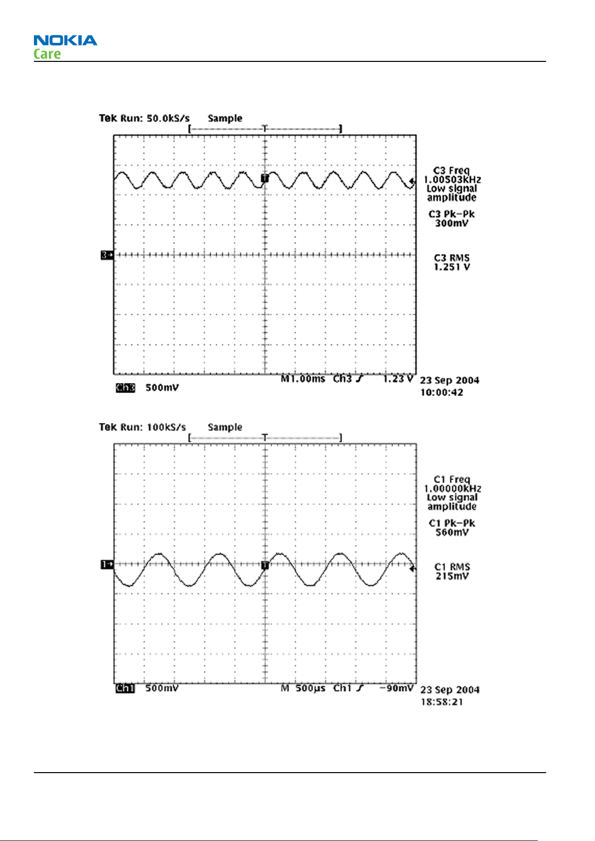
Figure 13 Single-ended output waveform of the Ext_in_HP_out measurement when earpiece is connected.
If a special low-pass filter designed for measuring digital amplifiers is unavailable, the measurement must be performed with a
current probe and the input signal frequency must be 2kHz.
Figure 14 Differential output waveform of the Ext_in_IHF_out out loop measurement when speaker is connected.
Page 3 –42 COMPANY CONFIDENTIAL Issue 1
Copyright © 2008 Nokia. All rights reserved.
Page 87

RM-325
BB Troubleshooting and Manual Tuning Guide
Figure 15 Single-ended output waveform of the HP_in_Ext_out loop when microphone is connected.
Issue 1 COMPANY CONFIDENTIAL Page 3 –43
Copyright © 2008 Nokia. All rights reserved.
Page 88
Internal earpiece troubleshooting
Troubleshooting flow
RM-325
BB Troubleshooting and Manual Tuning Guide
Page 3 –44 COMPANY CONFIDENTIAL Issue 1
Copyright © 2008 Nokia. All rights reserved.
Page 89

RM-325
BB Troubleshooting and Manual Tuning Guide
Internal microphone troubleshooting
Troubleshooting flow
Issue 1 COMPANY CONFIDENTIAL Page 3 –45
Copyright © 2008 Nokia. All rights reserved.
Page 90

Internal handsfree (IHF) troubleshooting
Troubleshooting flow
RM-325
BB Troubleshooting and Manual Tuning Guide
Page 3 –46 COMPANY CONFIDENTIAL Issue 1
Copyright © 2008 Nokia. All rights reserved.
Page 91

RM-325
BB Troubleshooting and Manual Tuning Guide
External earpiece troubleshooting
Troubleshooting flow
Issue 1 COMPANY CONFIDENTIAL Page 3 –47
Copyright © 2008 Nokia. All rights reserved.
Page 92
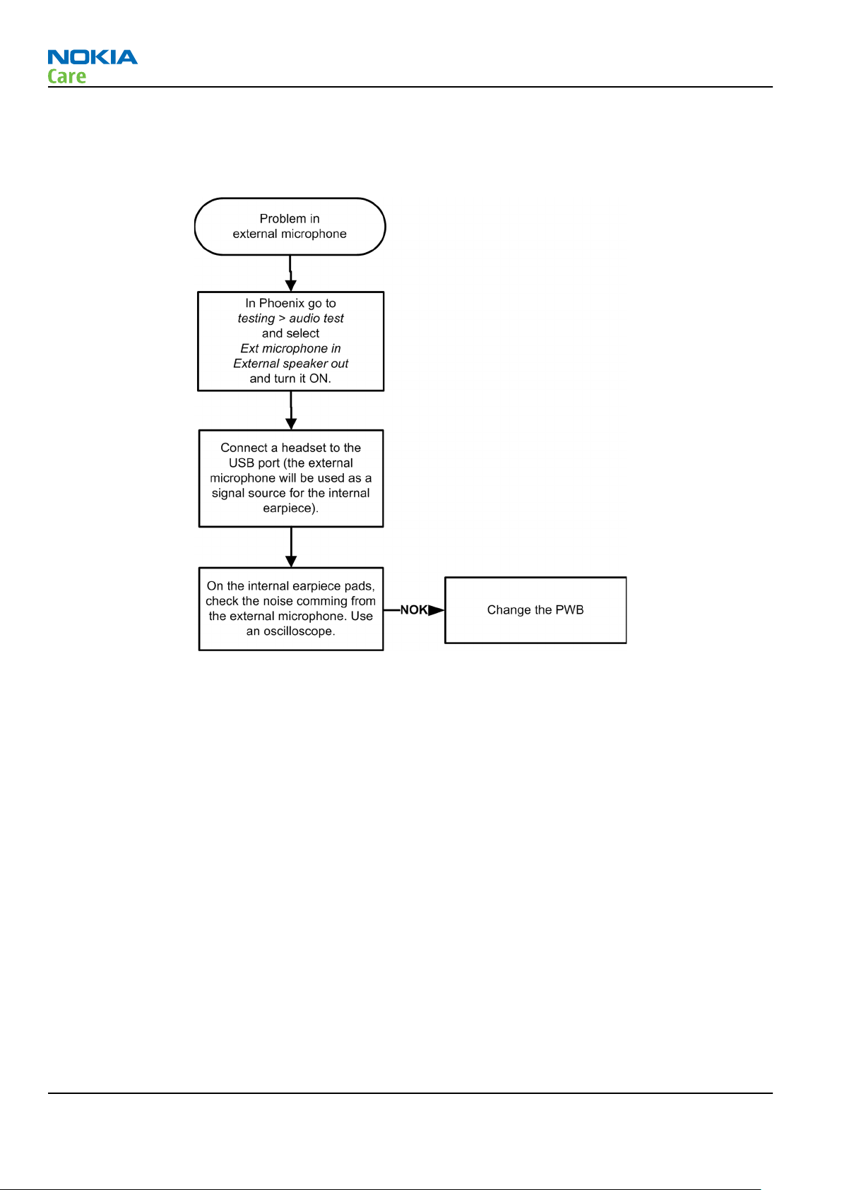
External microphone troubleshooting
Troubleshooting flow
RM-325
BB Troubleshooting and Manual Tuning Guide
Page 3 –48 COMPANY CONFIDENTIAL Issue 1
Copyright © 2008 Nokia. All rights reserved.
Page 93

RM-325
BB Troubleshooting and Manual Tuning Guide
Vibra troubleshooting
Troubleshooting flow
Issue 1 COMPANY CONFIDENTIAL Page 3 –49
Copyright © 2008 Nokia. All rights reserved.
Page 94

Bluetooth troubleshooting
Troubleshooting flow
RM-325
BB Troubleshooting and Manual Tuning Guide
Figure 16 Troubleshooting diagram: Bluetooth
Baseband manual tuning guide
Certificate restoring for BB5 products
Context
This procedure is performed when the device certificate is corrupted for some reason.
All tunings (RF & Baseband, UI) must be done after performing the certificate restoring procedure.
The procedure for certificate restoring is the following:
• Flash the phone with the latest available software using FPS-8 or FPS-10.
Note: USB flashing does not work for a dead BB5 phone.
• Create a request file.
• Send the file to Nokia by e-mail. Use the following addresses depending on your location:
Page 3 –50 COMPANY CONFIDENTIAL Issue 1
Copyright © 2008 Nokia. All rights reserved.
Page 95

RM-325
BB Troubleshooting and Manual Tuning Guide
• APAC: sydney.service@nokia.com
• CHINA: repair.ams@nokia.com
• E&A: salo.repair@nokia.com
• AMERICAS: fls1.usa@nokia.com
• When you receive a reply from Nokia, carry out certificate restoring.
• Tune the phone completely.
Note: SX-4 smart card is needed.
• If the phone resets after certificate restoring, reflash the phone again.
Required equipment and setup:
•
Phoenix
• The latest phone model specific
• PKD-1 dongle
• SX-4 smart card (Enables BB5 testing and tuning features)
• External smart card reader
• Activated FPS-8 flash prommer OR FPS-10 flash prommer
• Flash update package 03.18.004 or newer for FPS-8 or FPS-10 flash prommers
• CU-4 control unit
• USB cable from PC USB Port to CU-4 control unit
• Phone model specific adapter for CU-4 control unit
• PCS-1 cable to power CU-4 from external power supply
• XCS-4 modular cable between flash prommer and CU-4
service software v 2007.19 or newer.
Phoenix
Note: The smart card reader is only needed when FPS-8 is used. FPS-10 has an integrated smart card
reader.
Note: CU-4 must be supplied with +12 V from an external power supply in all steps of certificate
restoring.
data package.
Steps
1. Program the phone software.
i Start
ii Update the phone MCU software to the latest available version.
iii Choose the product manually from File→Open Product , and click OK.
iv Go to Flashing→SW Update and wait until
Issue 1 COMPANY CONFIDENTIAL Page 3 –51
Phoenix
If the new flash is empty and the phone cannot communicate with
Wait for the phone type designator (e.g. “RM-1” ) to be displayed in the status bar.
picture.
and login. Make sure the connection has been managed correctly for FPS-8 or FPS-10.
Phoenix
Copyright © 2008 Nokia. All rights reserved.
reads the product data as shown in the following
Phoenix
, reflash the phone.
Page 96

RM-325
BB Troubleshooting and Manual Tuning Guide
Product is automatically set according to the phone support module which was opened manually,
but the flash files cannot be found because the correct data cannot be read from the phone
automatically.
Code must be chosen manually, it determines the correct flash files to be used. Please choose the
correct product code (can be seen in the phone type label) from the dropdown list.
Flash Type must be set to Phone as Manufactured.
v To continue, click Start.
Progress bars and messages on the screen show actions during phone programming, please wait.
Page 3 –52 COMPANY CONFIDENTIAL Issue 1
Copyright © 2008 Nokia. All rights reserved.
Page 97

RM-325
BB Troubleshooting and Manual Tuning Guide
Programming is completed when Flashing Completed message is displayed.
The product type designator and MCU SW version are displayed in the status bar.
vi Close the
2. Create a
For this procedure, you must supply +12 V to CU-4 from an external power supply.
i To connect the phone with
ii Choose Tools→Certificate Restore .
iii To choose a location for the request file, click Browse.
SW Update
Request
file.
window and then choose File→Close Product .
Phoenix
, choose File→Scan Product .
Issue 1 COMPANY CONFIDENTIAL Page 3 –53
Copyright © 2008 Nokia. All rights reserved.
Page 98

BB Troubleshooting and Manual Tuning Guide
iv Name the file so that you can easily identify it, and click Open.
The name of the file and its location are shown.
RM-325
v To create the
vi When the file for certificate restore has been created, send it to Nokia as an e-mail attachment.
3. Restore certificate.
For this procedure, you must supply +12 V to CU-4 from an external power supply.
i Save the reply file sent by Nokia to your computer.
ii Start
iii Choose File→Scan Product .
Phoenix
Request
service software.
file, click Start.
Page 3 –54 COMPANY CONFIDENTIAL Issue 1
Copyright © 2008 Nokia. All rights reserved.
Page 99
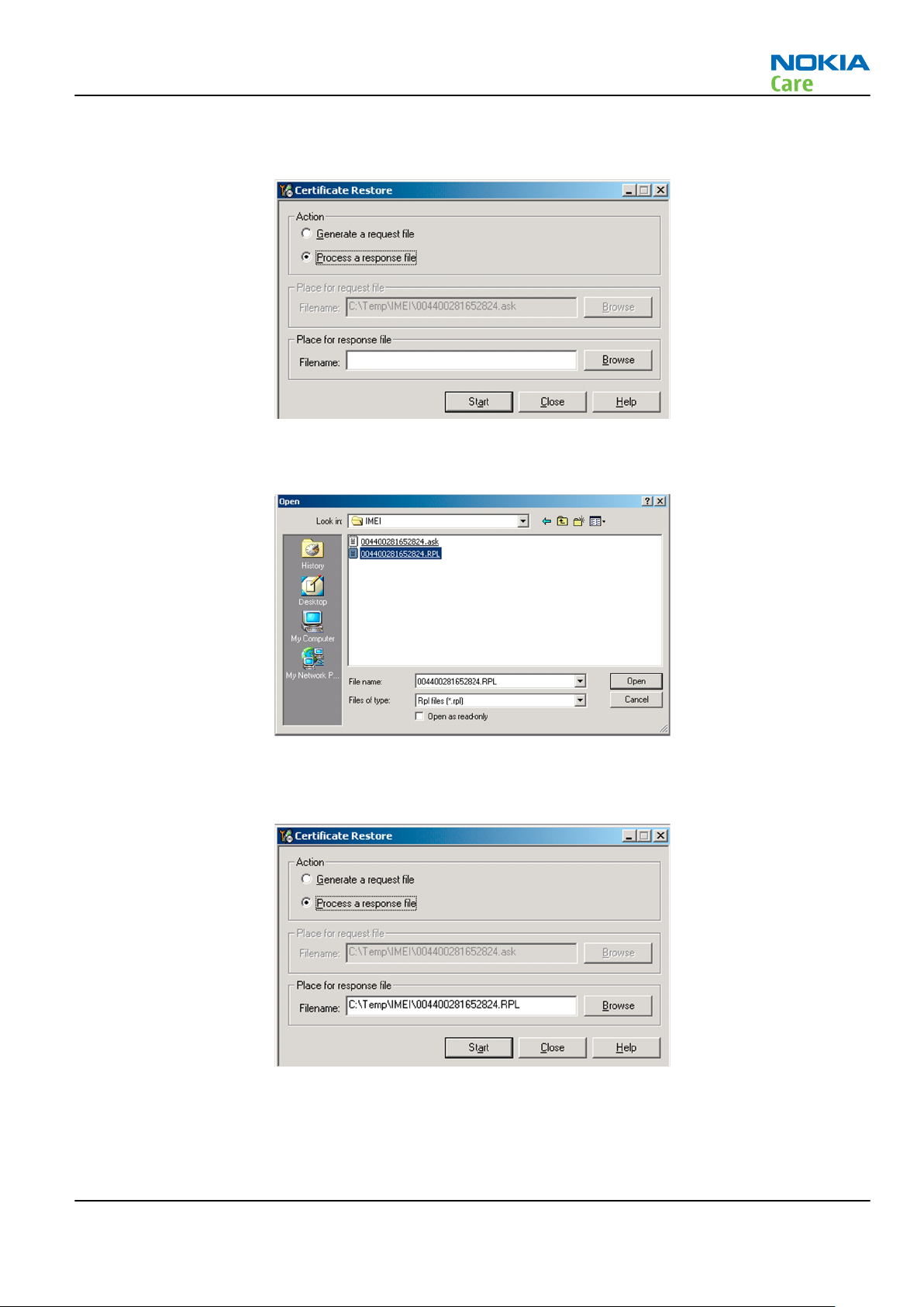
RM-325
BB Troubleshooting and Manual Tuning Guide
iv From the Tools menu, choose Certificate Restore and select Process a response file in the
pane.
v To choose the location where response file is saved, click Browse.
vi Click Open.
Action
The name of the file and the path where it is located are shown.
vii To write the file to phone, click Start.
Next actions
After a successful rewrite, you must retune the phone completely by using
Important: Perform all tunings: RF, BB, and UI.
Issue 1 COMPANY CONFIDENTIAL Page 3 –55
Copyright © 2008 Nokia. All rights reserved.
Phoenix
tuning functions.
Page 100
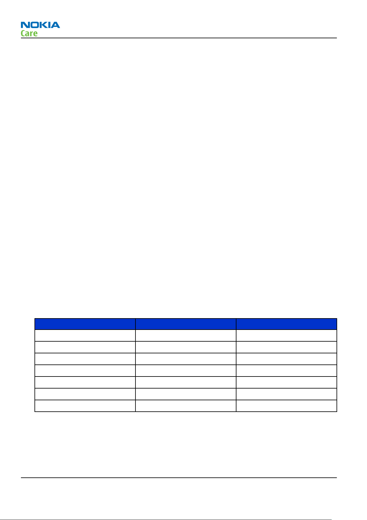
RM-325
BB Troubleshooting and Manual Tuning Guide
Energy management calibration
Prerequisites
Energy Management (EM) calibration is performed to calibrate the setting (gain and offset) of AD converters
in several channels (that is, battery voltage, BSI, battery current) to get an accurate AD conversion result.
Hardware setup:
• An external power supply is needed.
• Supply 12V DC from an external power supply to CU-4 to power up the phone.
• The phone must be connected to a CU-4 control unit with a product-specific flash adapter.
Steps
1. Place the phone to the docking station adapter (CU-4 is connected to the adapter).
2. Start
3. Choose File→ Scan Product.
4. Choose Tuning→Energy Management Calibration.
5. To show the current values in the phone memory, click Read, and check that communication between
6. Check that the CU-4 used check box is checked.
7. Select the item(s) to be calibrated.
8. Click Calibrate.
Phoenix
the phone and CU-4 works.
Note: ADC calibration has to be performed before other item(s). However, if all calibrations are
selected at the same time, there is no need to perform the ADC calibration first.
The calibration of the selected item(s) is carried out automatically.
The candidates for the new calibration values are shown in the
calibration values seem to be acceptable (please refer to the following "Calibration value limits" table),
click Write to store the new calibration values to the phone permanent memory.
service software.
Calculated values
column. If the new
Table 8 Calibration value limits
Parameter Min. Max.
ADC Offset -20 20
ADC Gain 12000 14000
BSI Gain 1100 1300
VBAT Offset 2400 2650
VBAT Gain 19000 23000
VCHAR Gain N/A N/A
IBAT (ICal) Gain 7750 12250
9. Click Read, and confirm that the new calibration values are stored in the phone memory correctly. If the
values are not stored to the phone memory, click Write and/or repeat the procedure again.
10. To end the procedure, close the
Page 3 –56 COMPANY CONFIDENTIAL Issue 1
Energy Management Calibration
Copyright © 2008 Nokia. All rights reserved.
window.
 Loading...