

Page 1

Customer Care Solutions
Technical Documentation
4 - Service T ools
ISSUE 2 01/2004 COMPANY CONFIDENTIAL 1
Copyright © 2003 Nokia. All Rights Reserved.
Page 2

NHL-10
CCS Technical Documentation Service Tools
This page has been deliberately left blank
2 COMPANY CONFIDENTIAL ISSUE 2 01/2004
Copyright © 2003 Nokia. All Rights Reserved.
Page 3

NHL-10
Service Tools CCS Technical Documentation
Table of Contents
Page No
JBV-1 Docking Station and DA-2 Adapter ...................................................................5
MJ-2 Module Jig ............................................................................................................6
RJ-2 Soldering Jig ......................................................................................................... 9
SF-2 POS (Point of Sales) Flash Adapter ....................................................................10
SW Security Device PKD-1 ........................................................................................11
FLS-4S POS (Point of Sale) Flash Device (Sales Pack) .............................................12
FPS-8 FLASH Prommer (Sales Pack) ......................................................................... 13
ACF-8 Universal Power Supply .................................................................................. 14
FPS-8C Parallel FLASH Prommer (Sales Pack) ......................................................... 15
FLC-2 DC Cable ..........................................................................................................16
AXS-4 Service Cable .................................................................................................. 17
DAU-9S MBUS Cable ................................................................................................18
XCS-1 Service Cable ................................................................................................... 19
PCS-1 Power Cable .....................................................................................................20
XRF-1 RF Cable .......................................................................................................... 21
XRS-11 RF Cable ........................................................................................................ 22
SCB-3 DC Cable ......................................................................................................... 23
XCS-4 Modular Cable ................................................................................................. 24
Printer Cable ................................................................................................................ 25
SRT-9 Camera Removal Tool .....................................................................................26
SS-12 Disassembly Jig ................................................................................................ 27
LRK-2 / 3 LGA component rework kits 1 & 2 ........................................................... 28
MJS-76 PA LGA re-work jig (Product code 0770417) ...............................................30
SA-20 RF Support Adapter ......................................................................................... 31
JBT-9 Bluetooth Test & Interface box(Sales Pack) .................................................... 32
ISSUE 2 01/2004 COMPANY CONFIDENTIAL 3
Copyright © 2003 Nokia. All Rights Reserved.
Page 4

NHL-10
CCS Technical Documentation Service Tools
This page has been deliberately left blank
4 COMPANY CONFIDENTIAL ISSUE 2 01/2004
Copyright © 2003 Nokia. All Rights Reserved.
Page 5
NHL-10
Service Tools CCS Technical Documentation
JBV-1 Docking Station and DA-2 Adapter
The JBV-1 Docking Station has been designed for calibration and software update use.
The DA-2 Docking Station Adapter makes signal connections to the phone. JBV-1 and DA-2
are used as one unit.
JBV-1 main electric functions are:
• adjustable VBATT calibration voltage, current measurement limit voltage”VCHAR”, current measurement calibration current”ICHAR”
• adjustable ADC calibration voltage via BTEMP and BSI signal
• BTEMP and BSI calibration resistor
• signals from FBUS to the phone via parallel jig
• control via FBUS or USB
• Flash OK/FAIL indication
In calibration mode JBV-1 is powered by external power supply 11-16V DC. In flashing power
for the phone can be taken from FPS-8 or external power supply 11-16V DC.
Product Code
JBV-1 Docking Station: 0770298
DA-2 Docking Station Adapter: 0770500
View of DA-2
Figure 1: DA-2
ISSUE 2 01/2004 COMPANY CONFIDENTIAL 5
Copyright © 2003 Nokia. All Rights Reserved.
Page 6
NHL-10
CCS Technical Documentation Service Tools
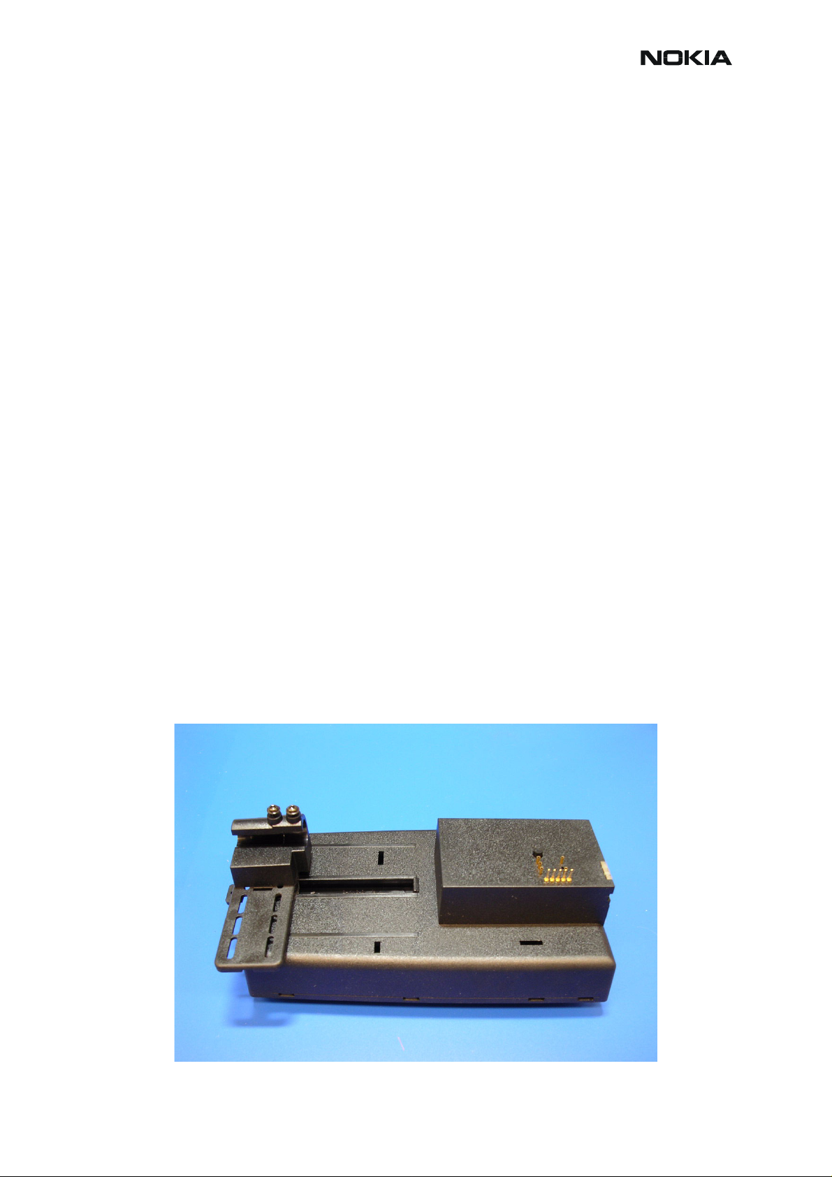
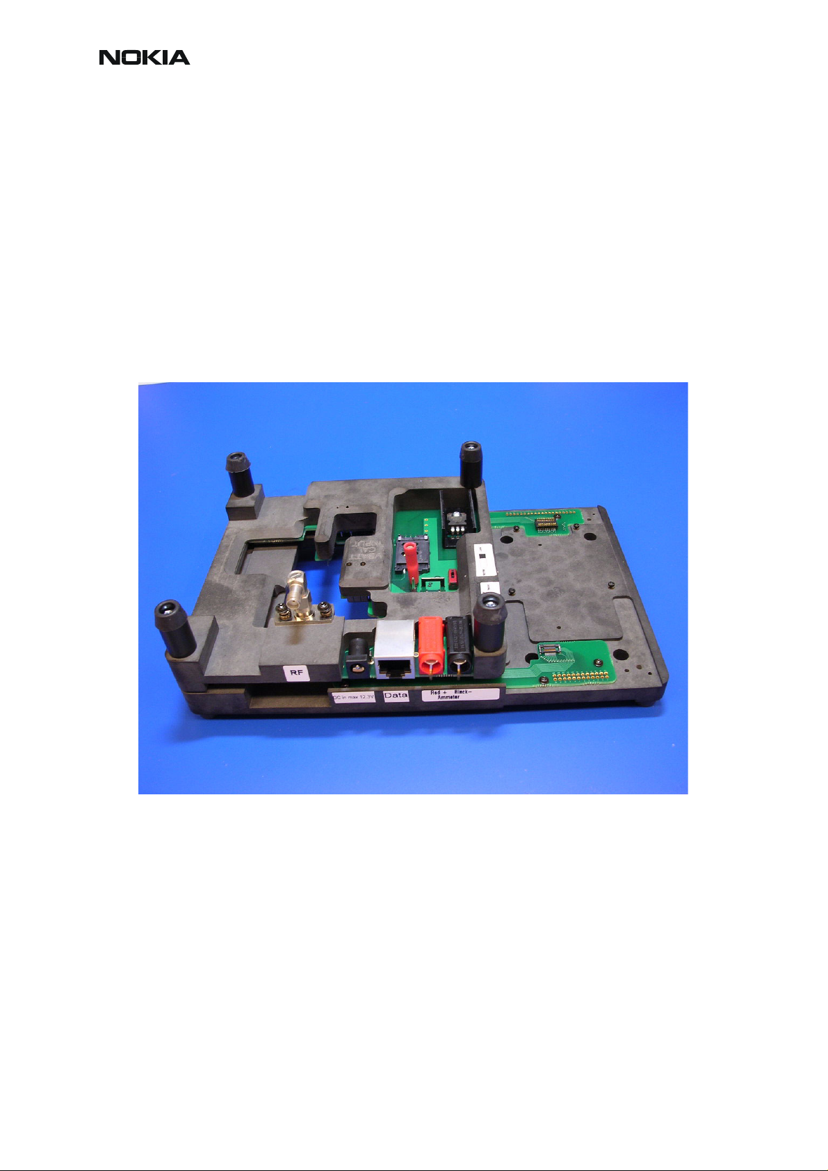
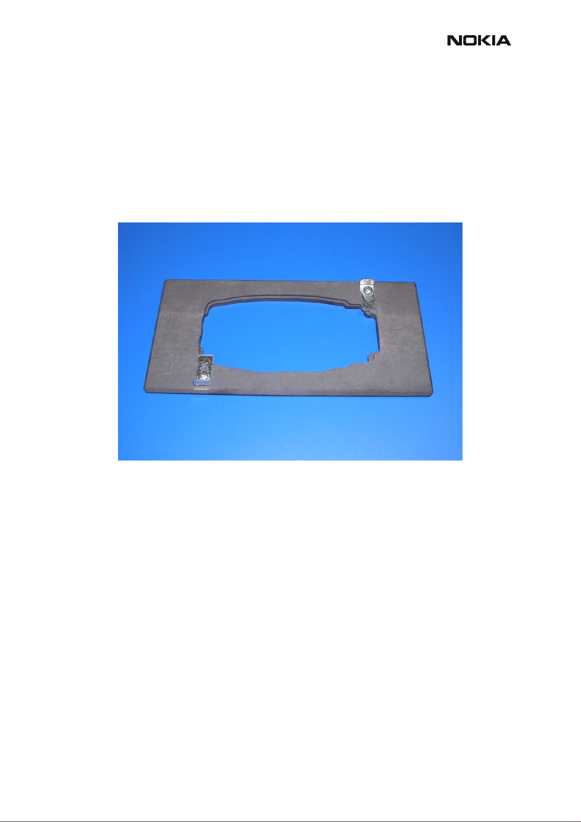
MJ-2 Module Jig
The MJ-2 Module Jig is used for testing the following modules:
• User interface
• Baseband and RF on system module
Product Code
MJ-2 Module Jig: 0770501
View of MJ-2
Figure 2: MJ-2
Note:
The nominal supply voltage for MJ-2 is +6.0 V.
The supply voltage must not exceed +12.0 V (min. 5.0 V).
Supply jig only when J1=regulated position.
6 COMPANY CONFIDENTIAL ISSUE 2 01/2004
Copyright © 2003 Nokia. All Rights Reserved.
Page 7
NHL-10
Service Tools CCS Technical Documentation
Table 1: LCD Test Pin List
Pin Signal Name
1
2
3
4
5
6
7
8
9
10
11
12
13
GND
!WR
GND
D0
D1
D2
D3
GND
Vddi
Vdd
LEDGND
LEDin
LEDout
14
15
16
17
18
19
20
21
22
23
24
LEDGND
!CS
D/!C
GND
D7
D6
D5
D4
TE
!RD
!RES
ISSUE 2 01/2004 COMPANY CONFIDENTIAL 7
Copyright © 2003 Nokia. All Rights Reserved.
Page 8
NHL-10
CCS Technical Documentation Service Tools
Table 2: KEYPAD Test Pin List
Pin Signal Name
1
2
3
4
5
6
7
8
9
10
11
12
13
ROCKER4
ROCKER2
ROW0
ROW1
VKEYB
ROW2
ROW4
COL2
COL4
GND
ROCKER5
ROCKER3
ROCKER1
14
15
16
17
18
19
20
COL0
GND
ROW3
ROW5
COL1
COL3
COL5
8 COMPANY CONFIDENTIAL ISSUE 2 01/2004
Copyright © 2003 Nokia. All Rights Reserved.
Page 9
NHL-10
Service Tools CCS Technical Documentation
RJ-2 Soldering Jig
The Soldering Jig RJ-2 is used for soldering and as a rework jig for system module.
Product Code
RJ-2 Soldering Jig: 0770502
View of RJ-2
ISSUE 2 01/2004 COMPANY CONFIDENTIAL 9
Copyright © 2003 Nokia. All Rights Reserved.
Page 10
NHL-10
CCS Technical Documentation Service Tools
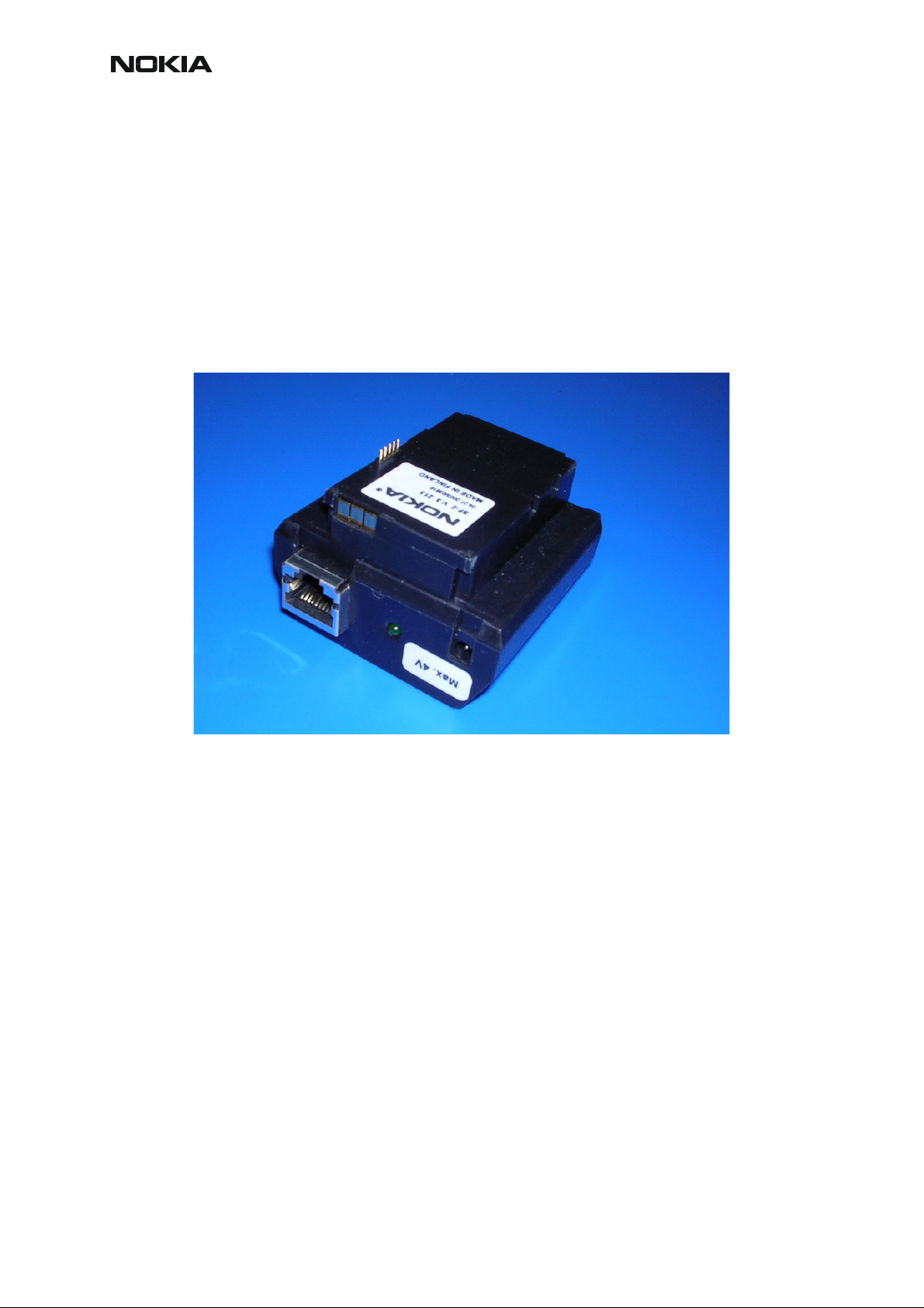
SF-2 POS (Point of Sales) Flash Adapter
The POS Flash Adapter SF-2 is used in the place of phone’s normal battery during service to
supply a controlled operating voltage and to connect to pads which are under the SIM card.
Product Code
SF-2 POS Flash Adapter: 0770506
View of SF-2
Figure 3: SF-2
10 COMPANY CONFIDENTIAL ISSUE 2 01/2004
Copyright © 2003 Nokia. All Rights Reserved.
Page 11

NHL-10
Service Tools CCS Technical Documentation
SW Security Device PKD-1
SW security device is a piece of hardware enabling the use of the service software when connected to the parallel (LPT) port of the PC. Without the dongle present it is not possible to use
the service software. Printer or any such device can be connected to the PC through the dongle
if needed.
Caution: Make sure that you have switched off the PC and the printer before making connections!
Caution: Do not connect the PKD-1 to the serial port.
Product Code
SW Security Device PKD-1: 0750018
View of PKD-1
Figure 4: PKD-1
ISSUE 2 01/2004 COMPANY CONFIDENTIAL 11
Copyright © 2003 Nokia. All Rights Reserved.
Page 12

NHL-10
CCS Technical Documentation Service Tools
FLS-4S POS (Point of Sale) Flash Device (Sales Pack)
FLS-4S is a dongle and flash device incorporated into one package, developed specifically for
POS use.
Product Code
FLS-4S Sales Pack – Europe/Africa: 0080541
FLS-4S Sales Pack – APAC: 0080542
FLS-4S Sales Pack – Americas: 0080543
View of FLS-4S
Figure 5: FLS-4S
12 COMPANY CONFIDENTIAL ISSUE 2 01/2004
Copyright © 2003 Nokia. All Rights Reserved.
Page 13

NHL-10
Service Tools CCS Technical Documentation
FPS-8 FLASH Prommer (Sales Pack)
The FLASH Prommer FPS-8 is used for example with SF-2, DA-2 and JBV-1. Power is supplied to FPS-8 from the Universal Power Supply.
The sales pack includes:
• FPS-8 Flash Prommer (0750123)
• FPS-8 Activation Sheet (9359289)
• ACF-8 Universal Power Supply (0680032)
• AXS-4 Service Cable (D9-D9) (0730090)
• Printer Cable (0730029)
Sales package code
FPS-8 Flash Prommer: 0080321
View of FPS-8
Figure 6: FPS-8
ISSUE 2 01/2004 COMPANY CONFIDENTIAL 13
Copyright © 2003 Nokia. All Rights Reserved.
Page 14

NHL-10
CCS Technical Documentation Service Tools
ACF-8 Universal Power Supply
ACF-8 Universal Power Supply is used to power FPS-8. ACF-8 has 6V DC and 2.1A output.
Product Code
ACF-8 Universal Power Supply: 0680032
View of ACF-8
Figure 7: ACF-8
14 COMPANY CONFIDENTIAL ISSUE 2 01/2004
Copyright © 2003 Nokia. All Rights Reserved.
Page 15

NHL-10
Service Tools CCS Technical Documentation
FPS-8C Parallel FLASH Prommer (Sales Pack)
The Parallel FLASH Prommer FPS-8C is used for example with SF-2, DA-2 and JBV-1. Fla sh
programming can be done to maximum of 8 phones parallel. FPS-8C consists of eight SF11C
programming cards. SF11C card is functionally identical to FPS-8.
Sales package code
FPS-8C Parallel Flash Prommer: 0080396
View of FPS-8C
Figure 8: FPS-8C
ISSUE 2 01/2004 COMPANY CONFIDENTIAL 15
Copyright © 2003 Nokia. All Rights Reserved.
Page 16

NHL-10
CCS Technical Documentation Service Tools
FLC-2 DC Cable
FLC-2 is used to supply a controlled operating voltage.
Product Code
FLC-2 DC Cable: 0730185
View of FLC-2
Figure 9: FLC-2
16 COMPANY CONFIDENTIAL ISSUE 2 01/2004
Copyright © 2003 Nokia. All Rights Reserved.
Page 17

NHL-10
Service Tools CCS Technical Documentation
AXS-4 Service Cable
The AXS-4 D9-D9 Service Cable is used to connect two 9 pin D connectors for example between PC and FPS-8. Cable length is 2 meters.
Product Code
AXS-4 D9-D9 Service Cable: 0730090
View of AXS-4
Figure 10: AXS-4
ISSUE 2 01/2004 COMPANY CONFIDENTIAL 17
Copyright © 2003 Nokia. All Rights Reserved.
Page 18

NHL-10
CCS Technical Documentation Service Tools
DAU-9S MBUS Cable
The MBUS Cable DAU-9S has a modular connector and is used for example between the PC`s
serial port and Module jig MJ-2, SF-2 or JBV-1.
Product Code
DAU-9S MBUS Cable: 0730108
View of DAU-9S
Figure 11: DAU-9S
18 COMPANY CONFIDENTIAL ISSUE 2 01/2004
Copyright © 2003 Nokia. All Rights Reserved.
Page 19

NHL-10
Service Tools CCS Technical Documentation
XCS-1 Service Cable
The XCS-1 Service Cable is used to connect FLS-4S to SF-2.
Product Code
XCS-1 Service Cable: 0730218
View of XCS-1
Figure 12: XCS-1
ISSUE 2 01/2004 COMPANY CONFIDENTIAL 19
Copyright © 2003 Nokia. All Rights Reserved.
Page 20

NHL-10
CCS Technical Documentation Service Tools
PCS-1 Power Cable
The PCS-1 Power Cable (DC) is used to connect for example JVB-1 to FPS-8.
Product Code
PCS-1 Power Cable: 0730012
View of PCS-1
Figure 13: PCS-1
20 COMPANY CONFIDENTIAL ISSUE 2 01/2004
Copyright © 2003 Nokia. All Rights Reserved.
Page 21

NHL-10
Service Tools CCS Technical Documentation
XRF-1 RF Cable
The XRF-1 RF Cable is used to connect for example Module jig MJ-2 to RF measurement
equipment.
Product Code
XRF-1 RF Cable: 0730085
View of XRF-1
Figure 14: XRF-1
ISSUE 2 01/2004 COMPANY CONFIDENTIAL 21
Copyright © 2003 Nokia. All Rights Reserved.
Page 22

NHL-10
CCS Technical Documentation Service Tools
XRS-11 RF Cable
The XRS-11 RF Cable is used to connect RF measurement equipment to the phone with RF
connector SA-20.
Product Code
XRS-11 RF Cable: 0730265
View of XRS-11
Figure 15: XRS-11
22 COMPANY CONFIDENTIAL ISSUE 2 01/2004
Copyright © 2003 Nokia. All Rights Reserved.
Page 23

NHL-10
Service Tools CCS Technical Documentation
SCB-3 DC Cable
The DC Cable SCB-3 is used to connect JBV-1 to the phone, for example.
Product Code
SCB-3 DC Cable: 0730114
View of SCB-3
Figure 16: SCB-3
ISSUE 2 01/2004 COMPANY CONFIDENTIAL 23
Copyright © 2003 Nokia. All Rights Reserved.
Page 24

NHL-10
CCS Technical Documentation Service Tools
XCS-4 Modular Cable
XCS-4 is a shielded (one specially shielded conductor) modular cable for flashing and service
purposes.
Product Code
XCS-4 Modular Cable: 0730178
View of XCS-4
Figure 17: XCS-4
24 COMPANY CONFIDENTIAL ISSUE 2 01/2004
Copyright © 2003 Nokia. All Rights Reserved.
Page 25

NHL-10
Service Tools CCS Technical Documentation
Printer Cable
This cable is used to connect the PC to FPS-8.
Product Code
Printer Cable: 0730029
View of Printer Cable
Figure 18: Printer Cable
ISSUE 2 01/2004 COMPANY CONFIDENTIAL 25
Copyright © 2003 Nokia. All Rights Reserved.
Page 26

NHL-10
CCS Technical Documentation Service Tools
SRT-9 Camera Removal Tool
The Camera Removal Tool SRT-9 is used to remove the camera from its locking connector.
Product Code
SRT-9 Camera Removal Tool: 0770527
View of SRT-9
26 COMPANY CONFIDENTIAL ISSUE 2 01/2004
Copyright © 2003 Nokia. All Rights Reserved.
Page 27

NHL-10
Service Tools CCS Technical Documentation
SS-12 Disassembly Jig
The Disassembly Jig SS-12 is used for disassembling the phone.
Product Code
SS-12 Disassembly Jig: 0770722
View of SS-12
ISSUE 2 01/2004 COMPANY CONFIDENTIAL 27
Copyright © 2003 Nokia. All Rights Reserved.
Page 28

NHL-10
CCS Technical Documentation Service Tools
LRK-2 / 3 LGA component rework kits 1 & 2
Type designator
LRK-2 (0273645) Kit 1
MJS-76 LGA Re-work
SES-2 Stencil 0770415
SPS-2 Spreader 0770471
LRK-3 (0273646) Kit 2
SES-2 Stencil 0770415
SPS-2 Spreader 0770471
Description Part code
0770417
Jig
Rework procedure
Due to the large mechanical tolerance of the power amplifiers the following procedure is necessary:
1 Put the power amplifier into the MJS-76 rework jig. The PA should be placed in
the best fit location which is determined by placing the PA in the largest location
first, and if this is to large, re-position it to the next location. This should be carried out until the best fit location is found.
28 COMPANY CONFIDENTIAL ISSUE 2 01/2004
Copyright © 2003 Nokia. All Rights Reserved.
Page 29

NHL-10
Service Tools CCS Technical Documentation
2 Once the best fit location has been found, leave the PA there and put the stencil
on top of the jig and PA.
3 Put soldering paste on the PA properly.
4 Remove the stencil and the PA from the jig.
5 Start the soldering process.
ISSUE 2 01/2004 COMPANY CONFIDENTIAL 29
Copyright © 2003 Nokia. All Rights Reserved.
Page 30

NHL-10
CCS Technical Documentation Service Tools
MJS-76 PA LGA re-work jig (Product code 0770417)
Introduction
This tool is used in LGA type component reworking purposes in central service centers.
Part list
Part
number
1 Frame SME5S910 1
2 Cylindrical pin 3x12 640b003 1
3 Cylindrical pin 3x12 640B012 1
4 Type label 9380601 1
Name of Part
Material
code
Drawing
number
Exploded view
Qty
30 COMPANY CONFIDENTIAL ISSUE 2 01/2004
Copyright © 2003 Nokia. All Rights Reserved.
Page 31

NHL-10
Service Tools CCS Technical Documentation
SA-20 RF Support Adapter
The SA-20 RF Support Adapter is designed for supporting the XRS-11 RF Cable wh en the cable is connected to the phone for RF measurement.
The RF-support tool has three snap fittings to be attached to the phone B-cover.
Product Code
SA-20 RF Support Adapter: 0770606
View of SA-20
Figure 19: SA-20
ISSUE 2 01/2004 COMPANY CONFIDENTIAL 31
Copyright © 2003 Nokia. All Rights Reserved.
Page 32

NHL-10
CCS Technical Documentation Service Tools
JBT-9 Bluetooth Test & Interface box(Sales Pack)
The JBT-9 testbox is a generic device to perform Bluetooth Bit Error Rate testing and
doing cordless FBUS connection via Bluetooth. An ACP-8x charger is needed for BER testing
and AXS-4 cable in case of cordless testing interface usage.
Sales package includes:
• JBT-9 testbox (0770336)
• SMA stub antenna (066P056)
• Installation and warranty information (9360613)
Product Code
JBT-9 sales kit: 0081490
View of JBT-9 with antenna
Figure 20: JBT-9
32 COMPANY CONFIDENTIAL ISSUE 2 01/2004
Copyright © 2003 Nokia. All Rights Reserved.
 Loading...