


Installation Manual
Please read these instructions carefully and retain them in a safe place for future reference.
|
|
IX-02-151 |
Noby-220iR2 Installation Manual |
Page 1 |
Software Revision1-0 |
- |
- |
- |
|
|
Contents |
|
Page |
|
|
|
|
Noby-220iR2 Overview |
|
|
|
|
|
|
3 |
|
|
||
|
|
Installation and Commissioning |
6 |
|
|
|
|
|
Location and mounting the Noby-220iR2 |
6 |
|
|
|
|
|
|
|
|||
|
|
Connecting the 230VAC supply |
6 |
|
|
|
|
|
First power up |
|
|
|
|
|
|
|
7 |
|
|
|
|
|
Connecting the detectors |
|
|
|
|
|
|
7 |
|
|
||
|
|
Connecting the external sounders |
|
|
|
|
|
|
7 |
|
|
||
|
|
One-man test |
|
8 |
|
|
|
|
|
|
|
||
|
|
Automatic Re-sound Option |
8 |
|
|
|
|
|
Input / Output Terminals |
|
|
|
|
|
|
9 |
|
|
||
|
|
External Fault Input |
|
|
|
|
|
|
|
9 |
|
|
|
|
|
Fault Output |
|
|
|
|
|
|
|
9 |
|
|
|
|
|
interlink Data Bus |
|
|
|
|
|
|
|
10 |
|
|
|
|
|
interlink Programming |
|
10 |
|
|
|
|
LED Strobe / Lamp Output |
13 |
|
|
|
|
|
|
|
|||
|
|
Relay Output |
|
13 |
|
|
|
|
Engineer Disablement Options |
|
|
|
|
|
|
14 |
|
|
||
|
|
Panel Behaviour |
|
|
|
|
|
|
|
15 |
|
|
|
|
|
Audible alarms, faults & warnings |
|
|
|
|
|
|
15 |
|
|
||
|
|
Panel Reset |
|
|
|
|
|
|
|
15 |
|
|
|
|
|
LED Lamp and 230VAC Mains Loss |
15 |
|
|
|
|
|
Maintenance |
|
15 |
|
|
|
|
|
|
|
||
|
|
Troubleshooting |
|
16 |
|
|
|
|
Warnings & Cautions |
17 |
|
|
|
|
|
|
|
|||
|
|
Specification |
|
18 |
|
|
|
|
User Operation |
|
21 |
|
|
|
|
|
|
|
||
|
|
LED Display Indications |
22 |
|
|
|
Noby-220iR2 Installation Manual |
Page 2 |
|
|
Software Revision1-0 |
||
- |
|
|
- |
- |
||
Noby-220iR2 Overview
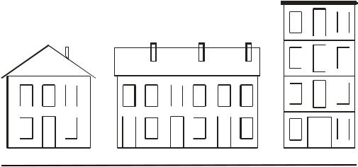
The Noby-220iR2 Fire Control Panel is an enhanced version of the standalone Noby-220, fitted with an interlink data bus for connecting up to 8 control panels. Fire Alarms and Fault Warnings are signalled across the interlink bus connection to alert neighbouring properties.
Local alarms are audibly signalled with a continuous sounder tone, whilst remotely triggered alarms are differentiated with pulsing sounders. The origin of a fire alarm is identified on the latching LED display at all remotely connected panels. A 60s delay on transmitted fire alarms provides a time window in which to cancel a nuisance false alarm.
Silencing the panel-in-alarm will automatically silence all connected panels, provided that no new alarm has been triggered from another panel. Each property owner can silence their own local sounders manually at their panel. All panels will re-sound upon receipt of a new fire alarm. Fire alarm LED indication is latched until a Panel Reset is performed at each individual property.
Fault LED indications remain latched at the local property until the panel is reset. Fault conditions originating from remote properties are displayed in real-time at the local panel, and the LED indications are automatically cleared when the remote panel is reset. Audible fault tones are only provided at the local property.
The Noby-220iR2 control panel is fully monitored according to EN54-2 and EN54-4 standards, and the interlink data connection is securely monitored for physical disconnection and/or data errors.
|
|
|
|
|
|
|
|
|
|
|
|
|
|
|
|
|
|
|
|
|
|
|
|
|
|
|
|
|
|
|
|
|
|
|
|
|
|
|
|
|
|
|
|
|
|
|
|
|
|
|
|
|
|
|
|
|
|
|
|
|
|
|
|
|
|
|
|
|
|
|
|
|
|
|
|
|
|
|
|
|
|
|
|
|
|
|
|
|
|
|
|
|
|
|
|
|
|
|
|
|
|
|
|
|
|
|
|
|
|
|
|
|
|
|
|
|
|
|
|
|
|
|
|
|
|
|
|
|
|
|
|
|
|
|
|
|
|
|
|
|
|
|
|
|
|
|
|
|
|
|
|
|
|
|
|
|
|
|
|
|
|
|
|
|
|
|
|
|
|
|
|
|
|
|
|
|
|
|
|
|
|
|
|
|
|
|
|
|
|
|
|
|
|
|
|
|
|
|
|
|
|
|
|
|
|
|
|
|
|
|
|
|
|
|
|
|
|
|
|
|
|
|
|
|
|
|
|
|
|
|
|
|
|
|
|
|
|
|
|
|
|
|
|
|
|
|
|
|
|
|
|
|
|
|
|
|
|
|
|
|
|
|
|
|
|
|
|
|
|
|
|
|
|
|
|
|
|
|
|
|
|
|
|
|
|
|
|
|
|
|
|
|
|
|
|
|
|
|
|
|
|
|
|
|
|
|
|
|
|
|
|
|
|
|
|
|
|
|
|
|
|
|
|
|
|
|
|
|
|
|
|
|
|
|
|
|
|
|
|
|
|
|
|
|
|
|
|
|
|
|
|
|
|
|
|
|
|
|
|
|
|
|
|
|
|
|
|
|
|
|
|
|
|
|
|
|
|
|
|
|
|
|
|
|
|
|
|
|
|
|
|
|
|
|
|
|
|
|
|
|
|
|
|
|
|
|
|
|
|
|
|
|
|
|
|
|
|
|
|
|
|
|
|
|
|
|
|
|
Noby-220iR2 Installation Manual |
|
|
|
|
Page 3 |
|
|
|
|
|
|
|
|
Software Revision1-0 |
||||||||||||||||||
- |
|
|
|
|
|
|
|
|
- |
|
- |
|||||||||||||||||||||
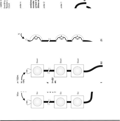
Figure 1: Detector and Sounder Circuits
Noby-220iR2 Installation Manual |
Page 4 |
Software Revision1-0 |
- |
- |
- |

Figure 2: |
Internal Layout |
|
Noby-220iR2 Installation Manual |
Page 5 |
Software Revision1-0 |
- |
- |
- |
Installation and Commissioning
This equipment is to be installed, serviced and maintained by a suitably qualified technical person with the requisite knowledge of electrical and fire safety installations.
Location and Mounting
It is best to locate the Noby-220iR2 in a public space, e.g. a hallway or landing area, where the LED Strobe/Lamp is visible and the internal alarm sounder can be clearly heard. Another consideration is to position the panel to make most effective use of the LED Strobe/Lamp, which switches on automatically in the event of mains power loss.
The Noby-220iR2 is intended for indoor use only, and must be sited in a dry environment. Do not site the Noby-220iR2 outside, or in any location where it may become exposed to damp or freezing conditions.
All components are selected to operate within their specification when the environmental conditions outside the enclosure comply with class 3k5 of EN60721-3-3:1995; temperature range -5°C to +40°C; 95%RH. The enclosure is rated at IP30, which offers protection against tools and wires greater than 2.5mm width, but no protection against liquids.
Mount the Noby-220iR2 securely onto a flat solid surface at the three fixing points denoted by ‘MH’ in Figure-2, using wall fixings appropriate for the material. In some situations it may be desirable to recess the panel into a hollow section wall, in which case the ‘Noby-220iR2 Flush Mounting Kit’ provides the necessary fixing harness and stainless steel frame.
Connecting the 230VAC supply
Connect the 230VAC to the Noby-220iR2, paying strict attention to local wiring regulations. A readily accessible disconnect device shall be incorporated into the building installation wiring. Feed the cable securely through the rear cable-entry hole CE2, or via a 20mm cable-gland CG4.
Alternatively a 3-core 230VAC flexible cord can be fed through CG5 (top) or CG6 (bottom) using the strain relief bush supplied (suitable for cable diameters 6.2mm to 7.4mm). In this case ensure that the cord is connected to the building installation wiring via a readily accessible disconnect device fitted with a 2A fuse.
Strip back the outer sheath of the cable 25mm and then strip back each inner core 6mm, such that the cable double insulation is preserved inside the enclosure to within 25mm of the screw terminals.
The Noby-220iR2 is Class-1 equipment and shall be earthed. Connect the earth core of the incoming cable to the earth point on the enclosure. Consult a qualified electrician if there are doubts concerning electrical safety.
Noby-220iR2 Installation Manual |
Page 6 |
Software Revision1-0 |
- |
- |
- |

First power up
It is recommended that the Noby-220iR2 is first powered up with the End Of Line devices still connected to the screw terminal block at the panel, as supplied from the factory. This will help to establish that the panel is functioning OK before connecting any external devices.
•Switch off or disconnect the 230VAC supply.
•Position the battery as shown in Figure-2, with the -'ve terminal to the rear of the enclosure.
•Connect the battery terminals, observing strict battery polarity.
•Press the pushbutton marked “Batt Start”.
•The panel powers up indicating a PSU fault, accompanied by a fault tone (2 beeps every 4s).
•The LED Strobe Lamp is automatically activated due to there being no 230VAC at this time.
•Switch on the 230VAC supply to the panel.
•The green Power LED blinks (occults) every 4 secs, indicating that 230VAC has been absent (memory).
• |
Perform a Panel Reset (refer to User Operation on page 21). |
• |
The Noby-220iR2 should now be in standby mode with a steady green Power LED and blue backlight. |
Connecting the detectors (Figure 1)
•Up to a maximum of 10 detectors can be connected to each zone.
•Up to a maximum of 10 call-points can be connected to each zone.
•Ensure that the detectors are within specification to operate at 10.5 volts.
•Use detector bases fitted with a schottky diode.
•Connect the detectors and call-points in a straight daisy-chain manner, with no spurs or loops.
•The recommended maximum cable length on each circuit is 100m.
•Maintain strict polarity from the panel, and from one detector to the next.
•Remove & re-connect the factory fitted EOLC at the outermost detector base.
Connecting the external sounders (Figure 1)
•The total combined sounder circuit current available across both circuits, is 150mA. e.g. up to 10 sounders can be connected with a current draw of 15mA each.
•The sounders must compatible with conventional fault monitoring (polarised).
•Ensure that the sounders are within specification to operate at 10.5 volts.
•Connect the sounders in a straight daisy-chain manner, with no spurs or loops.
•The recommended maximum sounder cable length is 100m per loop.
•Maintain strict polarity from the panel, and from one sounder to the next.
•Remove & re-connect the factory fitted EOLR at the outermost sounder.
Noby-220iR2 Installation Manual |
Page 7 |
Software Revision1-0 |
- |
- |
- |
One-man test
The one-man test is a test facility to aid commissioning and testing of the system, allowing the installer to walk-test the system and trigger each detection device in turn.
• |
Enter the Engineer Access Code-2 |
followed by |
|
. |
• |
Press either 1 and/or 2 to toggle on/off the desired zone/s for testing. |
|
|
|
•The selected zone/s are indicated by rotating LED patterns on the corresponding pushbutton/s.
•You now have 90s to trigger the first device, and 90s thereafter to trigger the next device.
•Each triggered device will pulse the sounders and flash the red zone LEDs until the test alarm condition is clear. The panel automatically resets the detectors. Note that the relay output remains unaffected by the one-man test mode.
•Press  to exit the one-man test mode.
Note: The panel automatically kicks back to normal standby User Mode after 90s of no activity, or if there is a real fire condition detected on a zone not being tested.
Automatic Re-sound – Programmable Option
It is a requirement of EN54-4 that it must be possible to configure the fire panel to automatically re-sound following an alarm in another zone. This is the default factory setting for the Noby-220iR2. The panel can be reconfigured to automatically re-sound following an alarm only in the same zone by clearing the option switch. From normal standby User Mode enter the following key sequence:
|
Engineer Access Code-1 |
|
|
|
Select |
|
Toggle |
|
Auto Re-sound Option |
|
|||
|
1 |
2 |
1 |
2 |
2 |
|
|
1 |
|
2 |
|
LEDs Off= No Auto Re-sound |
|
|
|
|
|
|
|
||||||||
|
|
|
|
|
|
||||||||
|
|
|
|
|
LEDs On= Auto Re-sound* |
|
|||||||
|
|
|
|
|
|
|
|
|
|
|
|
|
|
|
|
|
|
|
|
|
|
|
|
|
|
||
* Factory default setting |
|
|
|
|
|
|
|
|
|
|
|||
• The green Power LED flashes rapidly upon successfully entering the Engineer Access Code-1.
• |
The LEDs surrounding button 2 |
indicate the current option status. |
|
||
• |
Toggle button 2 to set/unset the desired option. |
|
|||
• |
Press |
|
to accept OR press |
to quit without updating the option. |
|
|
|
||||
Noby-220iR2 Installation Manual |
Page 8 |
Software Revision1-0 |
|||
- |
|
|
|
- |
- |
 Loading...