

Page 1
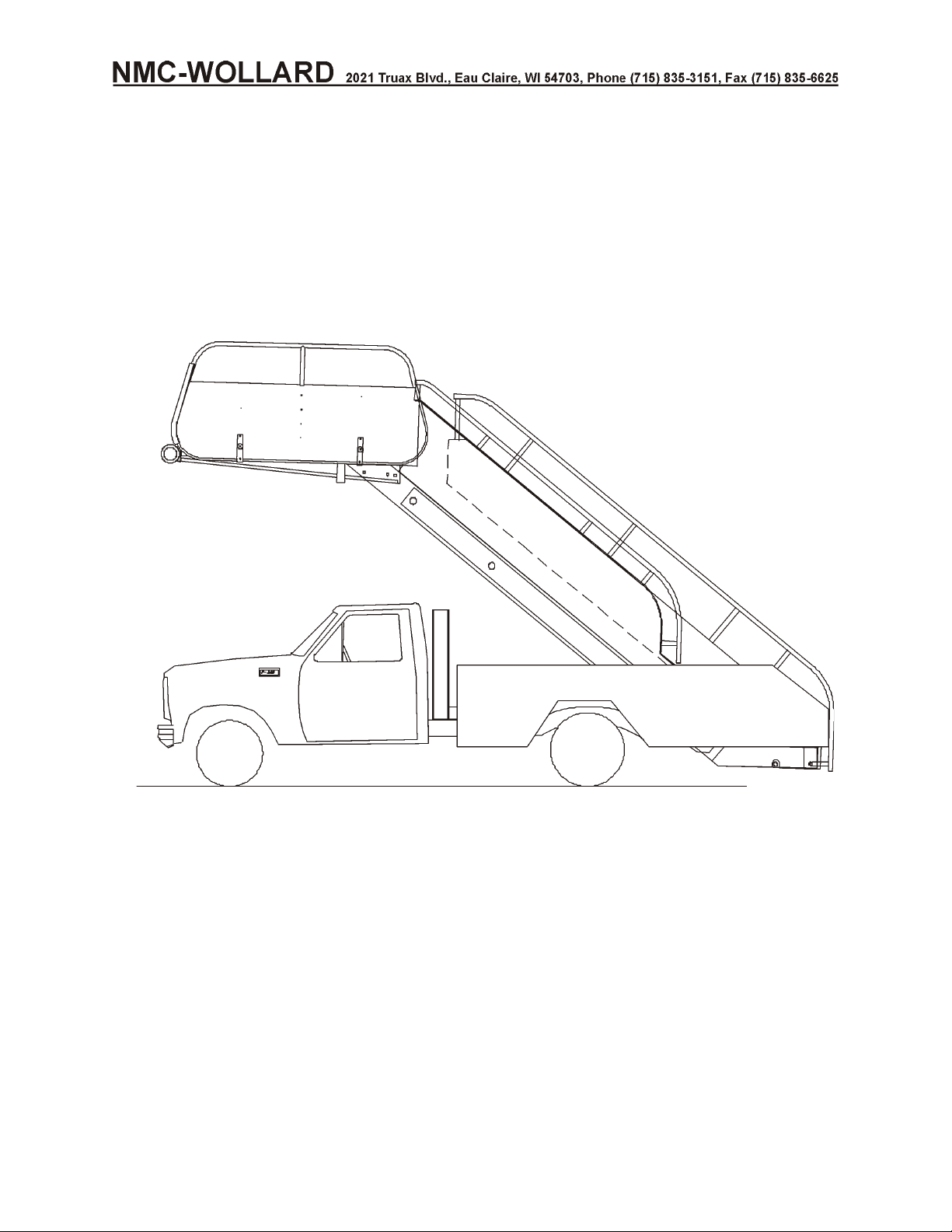
Truck Mounted Passenger Stair TMPS-200 Manual No. 307559
TRUCK MOUNTED
TO: 35A3-25-1
PASSENGER STAIR
OPERATION, MAINTENANCE AND PARTS
MANUAL
Model TMPS-200
Effective Starting S/N1378
NMC-Wollard, Inc.
2021 Truax Blvd.
Eau Claire, WI 54703
715-835-3151
FAX 715-835-6625
Web Site: nmc-wollard.com
General Email: [email protected]
Page 2
Truck Mounted Passenger Stair TMPS-200 Manual No. 307559
INTRODUCTION
Congratulations on the purchase of your new Truck Mounted Passenger Stair TMPS-200 from
NMC-Wollard, Inc. with its optional equipment this is the simplest, most flexible system on the market
today. With proper operation and preventative maintenance it will last for years.
This SAFETY ALERT SYMBOL indicates important safety messages in the
manual. When you see this symbol, be alert to the possibility of PERSONAL INJURY and
carefully read the message that follows.
Never operate without all covers, shields and guards in place. Body,
hair or clothing can become entangled in exposed, moving parts and can cause
serious injury or death.
Some covers and guards have been removed for illustrative/photographic purposes only in
this manual.
The Warranty appears in the front of this book. The order number and serial number are
recorded on page 24 of this section. These numbers are for your reference and for proper
identification of your machine by NMC-Wollard, Inc.
For information on ordering repair parts, refer to the Repair Parts chapter at the back of this
book.
You are urged to study this manual and follow the instructions carefully. Your efforts will be
repaid in better operation and service as well as a savings in time and repair expense. Failure
to read and understand the machine or the system could lead to serious injury. If you do not
understand the instructions in this manual contact the manufacturer.
This supercedes all previous published instructions.
When reading this manual, if a figure or paragraph outside the current section is referred to,
it will be identified by Chapter-Section-Figure Number or Chapter-Section-Paragraph.
Example:
Figure 2-2-4 Chapter 2-Section 2-Figure 4
2-2-1.4 Chapter 2-Section2-Paragraph 1.4
If figures or paragraphs from the current section are referred, the chapter and
section may not be referenced.
©Copyright NMC-Wollard, Inc. 2005
SEPTEMBER 30, 2008 INTRODUCTION
PAGE 2
Page 3

Truck Mounted Passenger Stair TMPS-200 Manual No. 307559
This manual is available on CD-ROM P/N 307559CD.
Keep a copy of your NMC-Wollard, Inc. manuals on your computer or CD-ROM! You
will be able to print and read pages. These manuals contain linked book marks and
hypertext links on the tables of contents. By mouse-clicking on a book mark or table
of contents entry, the page containing that item will automatically be displayed.
Requirements (minimum): PC with Windows 98 or newer, 486 processor (586
recommended), 8MB RAM, VGA monitor, mouse.
For availability and pricing, contact NMC-Wollard, Inc. customer service at:
Phone (715) 835-3151
Fax (715) 835-6625
Email [email protected]
©Copyright NMC-Wollard, Inc. 2008
INTRODUCTION SEPTEMBER 30, 2008
PAGE 3
Page 4

Truck Mounted Passenger Stair TMPS-200 Manual No. 307559
1 YEAR LIMITED WARRANTY
NMC-Wollard, Inc.
NMC-Wollard, Inc. warrants to the original owner that all components of the
equipment are free from defects in material and workmanship under normal use and
service for 12 months or 1,000 hours, whichever comes first, from the date of
shipment.
This warranty provides for NMC-Wollard, Inc. equipment components that fail
because of defects in material or workmanship during the warranty period, without
charge to the owner for parts or labor. The owner must provide prompt notice of the
defect and allow a reasonable time for replacement or repair.
This warranty applies only to parts manufactured by NMC-Wollard, Inc. Components
installed on NMC-Wollard, Inc. equipment but not manufactured by NMC-Wollard,
Inc. shall be covered under the original manufacturer's warranty. NMC-Wollard, Inc.
will assist in administering all such warranties, with the exception of tires, battery,
and other expendable parts, for which the owner will be required to deal directly with
the original manufacturer for warranty service. Neither tune-ups, normal
maintenance and repair or replacement of expendable parts (such as oil, lubricants,
belts, filters, tires, battery, etc.) are covered by this warranty.
This warranty does not cover damage resulting from carelessness or neglect;
accidents, fire, or other casualties; improper repair, operation, transportation, or
storage; or failure to provide necessary or appropriate maintenance. This warranty
does not cover deterioration or failure caused by chemicals, falling objects, dirt and
sand, or excessive heat or moisture. The NMC-Wollard, Inc. equipment must be
maintained according to the instructions provided with it or this warranty may be
considered void. Warranted components must be replaced with parts manufactured
or approved by NMC-Wollard, Inc. Warranty determination will be made after
NMC-Wollard, Inc. inspects the failed part.
NMC-Wollard, Inc. is not liable for damage or injury resulting from improper
installation, use, abuse, inability to use or misapplication of NMC-Wollard, Inc.
equipment, nor is NMC-Wollard, Inc. liable for damage resulting from equipment
repaired or modified by persons not authorized by NMC-Wollard, Inc. NMC-Wollard,
Inc. does not warrant any part or product to meet local, municipal, state, provincial,
or national laws or regulations.
This Limited Warranty is in lieu of all other warranties, whether express, implied, or
statutory. No other express warranty is given or authorized by NMC-Wollard, Inc.
NMC-Wollard, Inc. expressly disclaims any implied warranty of merchantability or
SEPTEMBER 30, 2008 INTRODUCTION
PAGE 4 1 YEAR LIMITED WARRANTY
Page 5

Truck Mounted Passenger Stair TMPS-200 Manual No. 307559
fitness for a particular purpose or otherwise. NMC-Wollard, Inc. shall not be liable
for loss of use of equipment, loss of time, loss of business, or for any other
incidental, or consequential damages. No authorized NMC-Wollard, Inc.
representative has the right to change or modify this warranty in any respect.
This warranty is non-transferable.
TO OBTAIN WARRANTY SERVICE
Warranty can be obtained by contacting NMC-Wollard, Inc., 2021 Truax Blvd., Eau
Claire, WI. 54703, (Phone 715 835-3151) (Fax 715 835-6625).
What should you do when you receive a new unit?
Check that you have received all the equipment ordered. Check inside the product
manual for engine warranties. Some OEM manufacturers supply a registration card
that must be filled out and returned immediately to initiate the warranty. If a survey
card or delivery checklist is enclosed from NMC-Wollard, Inc. please return it.
What should you do when you discover a possible warranty problem?
Call NMC-Wollard, Inc. (715-835-3151). We will require the serial number, number
of hours on the unit, and a description of the problem. You will be given a warranty
authorization number and assistance in troubleshooting.
IMPORTANT!
Clear and immediate communication with the factory is the key to obtaining a
satisfactory and timely resolution of your warranty problem.
Every warranty situation is different and so there are no hard rules. We will work with
your maintenance personnel and service managers to equitably resolve all claims.
What should you do after warranty problem has been resolved?
Complete and return the warranty claim form within 10 days. Place the assigned
warranty authorization number we gave you when you first called us with the
problem on your claim.
Return defective parts immediately. Your claim cannot be processed until all
defective parts have been returned to NMC-Wollard, Inc. Identify returned parts with
the assigned warranty authorization number.
INTRODUCTION SEPTEMBER 30, 2008
1 YEAR LIMITED WARRANTY PAGE 5
Page 6

Truck Mounted Passenger Stair TMPS-200 Manual No. 307559
What should you use for labor rate and labor time?
Labor rate are reviewed annually, if you do not have an established rate, call
NMC-Wollard, Inc. We do not publish a rate book; instead, we have accumulated
average times for repairs. We will authorize repair time once we have approved the
repair. If unforeseen circumstances cause a significantly greater repair time than
originally approved, please contact us before submitting your claim.
SEPTEMBER 30, 2008 INTRODUCTION
PAGE 6 1 YEAR LIMITED WARRANTY
Page 7

Truck Mounted Passenger Stair TMPS-200 Manual No. 307559
TABLE OF CONTENTS
1 YEAR LIMITED WARRANTY .............................4
TABLE OF CONTENTS .................................7
REVISION RECORD..................................16
REVISION HIGHLIGHTS ...............................17
PAGE EFFECTIVITY .................................21
CONFIGURATION ...................................24
EFFECTIVITY CODE .................................26
INTRODUCTION SEPTEMBER 30, 2008
TABLE OF CONTENTS PAGE 7
Page 8

Truck Mounted Passenger Stair TMPS-200 Manual No. 307559
CHAPTER 1 GENERAL INFORMATION & OPERATION
INSTRUCTIONS
TABLE OF CONTENTS
1 DESCRIPTION ..................................1
1.1 Product Safety ................................1
1.2 Safety Decals.................................2
1.2.1SAFETY SIGN CARE ..........................2
1.2.2HOW TO INSTALL SAFETY SIGNS ...................2
1.3 General Safety Precaution ..........................3
1.4 Equipment Description ............................6
1.4.1 Intended Usage .............................6
1.4.2 Description of the Passenger Stair ...................6
1.4.3 Reserved For Future Use ........................6
1.4.4Hydraulic hand pump ..........................9
1.4.5 Truck Section ..............................9
1.4.6 Lighting .................................9
1.4.7 Stabilizers................................9
1.4.8 Main Support Frame ..........................10
1.4.9 Forward Support Frame (A-Frame) ..................10
1.4.10 Stair Section .............................10
1.4.11 Main Section (Stationary Unit) ....................10
1.4.12 Adjustable Section (Telescoping Unit) ................11
1.4.13 Hydraulic Reservoir .........................11
1.4.14 Side Panels .............................11
1.4.15Canopy ................................11
1.4.16Other Features ............................11
2 OPERATION....................................1
2.1 Pre-Operation ................................1
2.2DAILY INSPECTION .............................1
2.2.1Hydraulic System ............................1
2.2.2Stair Unit ................................2
2.2.3General Chassis Check .........................2
2.2.4Electrical System ............................3
2.2.5Operational Check............................3
2.3 Driving the Unit ................................3
2.3.1Interlocks ................................3
2.4 Servicing Aircraft ...............................4
2.5DRIVING AWAY FROM AIRCRAFT .....................6
2.6Emer gency Pro ce dures ............................7
2.6.1Using the op tional hand pump ......................7
JANUARY 31, 2014 INTRODUCTION
PAGE 8 TABLE OF CONTENTS
Page 9

Truck Mounted Passenger Stair TMPS-200 Manual No. 307559
2.7Servicing Loading Facilities Other Than Aircraft ................9
3 SPECIFICATIONS AND CAPABILITIES ......................1
3.1 Aircraft Servicing Capability - 2005 & Later ..................1
3.1.1 Stair Capacity ..............................1
3.1.2 Height Range ..............................1
3.1.3 Dimensions ...............................1
3.1.4 Shipping Dimensions ..........................1
3.1.5 Operator Controls ............................1
3.1.6 Vehicle (standard) ...........................1
3.1.7 Truck Chassis..............................2
3.1.8 Brakes .................................2
3.1.9 Cab ...................................2
3.1.10 Electrical................................2
3.1.11 Shock Absorbers ...........................2
3.1.12 Steering ................................2
3.1.13 Transmission .............................2
3.1.14 Hydraulic System ...........................2
3.1.15 Options and Accessories .......................2
4 COMMISSIONING AND DECOMMISSIONING FOR
OPERATION AND SHIPPING ........................1
4.1 Commissioning/Decommissioning for Airport, Cross county or shipping ...1
4.2 Truck Chassis ................................1
4.2.1Front Spring Lockouts ..........................1
4.2.2Rear Spring U-Bolts ...........................2
4.3 Installing the Handrails ............................3
4.3.1Stair Handrails..............................3
4.3.2Platform Handrails (Wings) .......................4
4.4 Miscellaneous Preparation ..........................4
4.4.1Cleaning.................................4
4.5Floodlight ...................................4
4.5.1Movable Handrails............................5
4.5.2Stabilizers ................................5
4.5.3Hydraulic Oil ...............................5
4.5.4Fastenings ...............................5
4.5.5Operational Check............................5
4.6Record Aircraft Servicing Data ........................5
4.7 Shipping the Unit ...............................5
INTRODUCTION SEPTEMBER 30, 2008
TABLE OF CONTENTS PAGE 9
Page 10

Truck Mounted Passenger Stair TMPS-200 Manual No. 307559
CHAPTER 2 MAINTENANCE
TABLE OF CONTENTS
1 SERVICING ....................................1
1.1 NMC-Wollard, Inc. Torque Values ......................2
1.2 Preventative Maintenance ..........................3
1.2.1 Periodic Maintenance ..........................3
1.3 Hydraulic System - Special Instructions ...................3
1.3.1 Hydraulic System Safety ........................3
1.3.2 Hydraulic System – Special Instructions.................4
1.3.3 Changing Reservoir Oil .........................4
1.4 General Lubrication Diagram.........................5
2 TROUBLE SHOOTING ..............................1
2.1 Basic Troubleshooting - Hydraulic System ..................1
2.2 Basic Troubleshooting - Mechanical .....................2
2.3 Basic Troubleshooting - Electrical System ..................3
2.4 Electrical and Hydraulic Schematics and Diagrams .............4
3 REMOVAL AND INSTALLATION .........................1
3.1 Stair Assembly ................................1
3.1.1 Special Tools and Equipment ......................1
3.1.2 Stair Removal .............................1
3.1.3 Stair Installation ............................2
3.2 Separating and Mating Stair Sections ....................3
3.2.1 Separating Stair Sections........................3
3.2.2 Mating Stair Sections ..........................3
3.3 Stair Cylinder Removal and Replacement ..................4
3.3.1 Stair Cylinder Removal .........................4
3.4 A-Frame Removal and Installation ......................5
3.4.1 A-Frame Removal ...........................5
3.5 Main Stair Frame Removal and Installation..................5
3.5.1 Main Stair Frame Removal .......................5
3.5.2 Main Stair Frame Installation ......................6
3.6 Electrical Components Removal and Installation ...............6
3.7 Hydraulic System ..............................6
3.7.1 Hydraulic System Safety ........................6
3.7.2 Hydraulic System Procedures......................7
3.8 Wheel Mounting (Dual Rear Wheels).....................7
3.9 Installation and Removal of Optional Extended Stair .............8
3.9.1 Extended Stair Instructions .......................8
3.9.2 Removing the Step Platform Assembly .................9
3.9.3 Reinstalling the Step Platform Assembly ................9
SEPTEMBER 30, 2008 INTRODUCTION
PAGE 10 TABLE OF CONTENTS
Page 11

Truck Mounted Passenger Stair TMPS-200 Manual No. 307559
3.10 Installation of Optional Canopy ......................10
3.10.1 Deck Section.............................10
3.10.2 Lower Section ............................12
3.10.3 Final Assembly............................13
3.10.4 Upper Section ............................13
3.11 Ford 6.0L Diesel Clutch Pump Kit Installation ...............16
3.12 F350 V8/Gas Clutch Pump Installation ...................20
3.13 Deweze, Ford 5.4L, 2008+ Clutch Pump Installation ............22
4 REPAIRS .....................................1
4.1 Stabilizer Proximity..............................1
INTRODUCTION SEPTEMBER 30, 2008
TABLE OF CONTENTS PAGE 11
Page 12

Truck Mounted Passenger Stair TMPS-200 Manual No. 307559
CHAPTER 3 OVERHAUL/MAJOR REPAIR
TABLE OF CONTENTS
1 GENERAL REPAIRS ...............................1
1.1 General Information .............................1
1.2 Truck Chassis ................................1
SEPTEMBER 30, 2008 INTRODUCTION
PAGE 12 TABLE OF CONTENTS
Page 13

Truck Mounted Passenger Stair TMPS-200 Manual No. 307559
CHAPTER 4 REPAIR PARTS
TABLE OF CONTENTS
CHAPTER 4 REPAIR PARTS
1 HOW TO USE THE REPAIR PARTS CHAPTER ..................1
2 LIST OF VENDORS ................................1
3 NUMERICAL PART NUMBER LIST ........................1
4ILLUSTRATED PARTS LIST ............................1
Main Assembly ..................................2
A-Frame Assembly ................................6
Main Stair Assembly ...............................8
Handrail Assembly ...............................12
Adjustable Stair Assembly ...........................14
Wing Assembly, Platform ............................20
Adjustable Section Handrail...........................22
Main Stabilizer Assembly ............................24
Rear Stabilizer Assembly ............................26
Hydraulic Assembly ...............................28
Hydraulic Tank (SN 1378-1379).........................34
Hydraulic Manifold, Lift/Stabilizer ........................36
Tank, Heated, Option ..............................38
Electrical Assembly ...............................40
Solenoid Assembly ...............................46
Placards and Signs ...............................48
Placards, Special, Option ............................50
Beacon, Rotating, Option ............................52
Light, Warning, Amber, Option .........................54
Lights, Flood, Back-up, Option .........................56
Morse Control, Option - 2005+ .........................58
Morse Control Shifter Assembly.........................60
Gas Cap, Protect-O Seal Option ........................62
Alarm, Backup, Option .............................64
Stair and Deck Tread, Rubber, Option......................66
Platform, 3-Meter, Option ............................68
Stair Assembly, Extended, Option........................70
Canopy Assembly Option ............................72
Canopy, Installation & Assembly ........................74
Step Reinforcement Option ...........................76
Battery Jumper System Option .........................78
Option, HD Bumper F350, 1999-2000 ......................80
Option, HD Bumper F350, 2000-2008 ......................82
INTRODUCTION JANUARY 31, 2014
TABLE OF CONTENTS PAGE 13
Page 14

Truck Mounted Passenger Stair TMPS-200 Manual No. 307559
Option, HD Bumper, F350, 2009 ........................84
Governor, F350 gas, option ...........................88
Lights, Canadian Running, Option .......................90
Shut Down, Low Oil, Gas/DSL, Option (SN 1381+) ...............92
Harness Assemblies ..............................94
Wheel/Tire, F350 Current Year, Option .....................96
Fire Extinguisher, Option ............................98
Truck Prep, F350 6.0L Diesel (1 Of 2) .....................100
Truck prep, F350 V8 Gas (1 OF 2) .......................104
Hourmeter Installation Option, Diesel .....................108
Heat, Hydraulic Tank, Option .........................110
Outside Controls, Optional...........................112
Truck Prep, F350 V8 Gas, 2008+ .......................114
Pump Kit w/Clutch F350 V8, Gas, 2008+....................116
SEPTEMBER 30, 2008 INTRODUCTION
PAGE 14 TABLE OF CONTENTS
Page 15

Truck Mounted Passenger Stair TMPS-200 Manual No. 307559
CHAPTER 5 MANUFACTURERS’ INFORMATION
TABLE OF CONTENTS
Hydraforce Combination Valve ..........................2
DewEze 2005+ Clutch Pump Installation Instructions Part No. 308703 ......9
INTRODUCTION SEPTEMBER 30, 2008
TABLE OF CONTENTS PAGE 15
Page 16
Truck Mounted Passenger Stair TMPS-200 Manual No. 307559
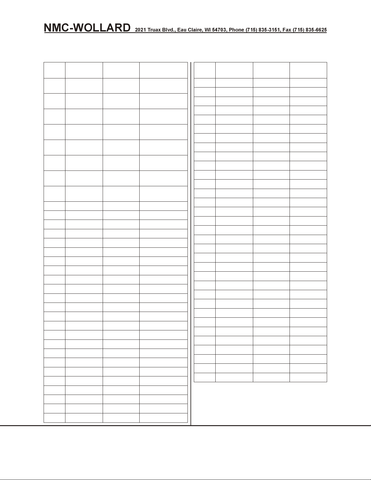
REVISION RECORD
Rev.
No.
Issue
Date
Date
Inserted
0 8/31/05 8/31/05
1 3/31/06 3/31/06
2 10/31/06 10/31/06
3 03/31/07 03/31/07
4 03/31/08 03/31/08
5 09/30/08 09/30/08
6 03/31/09 03/31/09
7 01/31/14 01/31/14
Initial
NMCWollard, Inc.
NMCWollard, Inc
NMCWollard, Inc
NMCWollard, Inc
NMCWollard
NMCWollard
NMCWollard
NMCWollard
Rev.
No.
Issue
Date
Date
Inserted
Initial
MARCH 31, 2009 INTRODUCTION
PAGE 16 REVISION RECORD
Page 17
Truck Mounted Passenger Stair TMPS-200 Manual No. 307559
REVISION HIGHLIGHTS
TO: HOLDERS OF NMC-Wollard, Inc. OPERATION AND MAINTENANCE
MANUAL NO. 307559, Truck Mounted Passenger Stair.
Pages that have been revised are outlined below, together with highlights of the
revision. Please delete and replace the affected pages and enter Revision No. And
date to the Revision Record page 16.
REVISION NO. 0 DATED 8/31/05
Chapter/Section
And Page No.
All
Description of Changes Eff
New manual for units starting with electrically
controlled hydraulics
1378+
REVISION NO. 1 DATED 3/31/06
Chapter/Section
And Page No.
Description of Changes Eff
Intro/11-12.16-20. Added Rev 1. Update pg eff. All
2/2/14-15. Update Schem 307556 All
REVISION NO. 2 DATED 10/31/06
Chapter/Section
And Page No.
Description of Changes Eff
Intro/7-10.11-12. Update TOC. Added Rev 2. All
1/TOC Updated All
1/1/2-3.4-5
1/2/2-8
Add 562A439,304272,304327,304335,305732.
Updated switch descriptions.
Updated aircraft servicing procedures, added
emergency pump operation. Daily chklst added
All
All
1/4/5 Added record a/c servicing data All
2/1/2 Bolt Chart Updated All
2/2/6-7. Update 307556.
4/TOC Updated All
4/3/1-4 Updated All
4/4/29.34-35.38-43.
46-47.62-106.
4/4/51.100-103.104105
Chng 304271 to 307719, update fig no’s.Chng SN
from 1381 to 1379, update fig number.Update
All
Elec Assy.Add 308379. Update Figure Numbers.
Add 308425. Add 305216 & 308380.Add 308433. Opt
INTRODUCTION SEPTEMBER 30, 2008
REVISION HIGHLIGHTS PAGE 17
Page 18
Truck Mounted Passenger Stair TMPS-200 Manual No. 307559
REVISION NO. 3 DATED 03/31/07
Chapter/Section
And Page No.
Intro/11,13,16,17,21
2/2/7,10
Description of Changes Eff
Rev Record/pg eff updated, Rev 3 added, SN eff
added.
Solenoid detail added to 307556-3. Updated
307612.
SN 1378+
SN 1378+
4/4/11 208647 added SN 1378+
4/4/13 302999, qty changed to 1 SN 1385+
4/4/28-31,33
Hydraulic components arranged to reflect modular
BOM
SN 1378+
REVISION NO. 4 DATED 03/31/08
Chapter/Section
And Page No.
Intro/9-10.11,13.
16-18
1/4/1.3.
Description of Changes Eff
Update Chap 4 TOC. Rev 3 added. Pg eff
updated.
Remove Tire Press. Update Rear Spring
Procedure.
All
All
2/2/11-12. Add 307575 Schem. All
4/4/36-37. 46-47.
38-106
307575 parts breakdown added. Update Solenoid
Assy. Pages Renumber
All
REVISION NO. 5 DATED 09/30/08
Chapter/Section
And Page No.
Description of Changes Eff
Intro/all pages Updated for Ansi Z535.6 format All
1/all pages Updated for Ansi Z535.6 format All
2/all pages Updated for Ansi Z535.6 format All
2/3/22
DewEze, Ford 5.4L, 2005+ Clutch Pump Installation
added.
2007+
3/all pages Updated for Ansi Z535.6 format All
4/TOC Updated All
4/3/1-4 Updated All
4/4/37. 108-111. F002547 + 308707 truck prep added. 2007+
5/1. 9-12
SEPTEMBER 30, 2008 INTRODUCTION
PAGE 18 REVISION HIGHLIGHTS
Update TOC.DewEze, Ford 5.4L, 2007+ Clutch
Pump Installation added.
2007+
Page 19
Truck Mounted Passenger Stair TMPS-200 Manual No. 307559
Revision No. 6 Dated 03-31-09
Chapter/Section
And Page No.
Description of Changes Eff
Intro/16,19,21 Rev 6 added, pg effectivity updated. all
2/1/4 Error corrected, 57 liters was 34. all
Revision No. 7 Dated 01-31-14
Chapter/Section
And Page No.
Description of Changes Eff
Intro/8,13,14 TOC Updated all
Intro/16,19,21-23,
25,26
Rev 7 added, pg effectivity updated, page 26 S/N
1378 was 1377, 309735 added to page 25
all
1/1/1,6 Controls and Instruments moved to 1/2/1-3 all
1/2/1-3 Added Controls and Instruments Section all
4/3/1-4 Index changed all
4/4/33 307601 deleted, 307591 added, 1.3712 filter added all
4/4/80,81 Added 303814 HD bumper Option F350,1999-2000 all
4/4/82,83 Added 2000-2008 to Fig. 33 heading all
4/4/84,85 Added 303814 HD bumper Option F350,2009 all
4/4/86,87 Added 309735 HD bumper option 309735 all
INTRODUCTION JANUARY 31, 2014
REVISION HIGHLIGHTS PAGE 19
Page 20

Truck Mounted Passenger Stair TMPS-200 Manual No. 307559
THIS PAGE INTENTIONALLY BLANK
SEPTEMBER 30, 2008 INTRODUCTION
PAGE 20 REVISION HIGHLIGHTS
Page 21

Truck Mounted Passenger Stair TMPS-200 Manual No. 307559
PAGE EFFECTIVITY
Chapter/Section Page Date
Cover 1 09/30/08
Introduction 2 09/30/08
Introduction 3 09/30/08
Limited Warranty 4 09/30/08
Limited Warranty 5 09/30/08
Limited Warranty 6 09/30/08
Table of Contents 7 09/30/08
Table of Contents 8 01/31/14
Table of Contents 9 09/30/08
Table of Contents 10 09/30/08
Table of Contents 11 09/30/08
Table of Contents 12 09/30/08
Table of Contents 13 01/31/14
Table of Contents 14 01/31/14
Table of Contents 15 09/30/08
Revision Record 16 03/31/09
Revision Highlights 17 09/30/08
Revision Highlights 18 09/30/08
Revision Highlights 19 01/31/14
Revision Highlights 20 09/30/08
Page Effectivity 21 01/31/14
Page Effectivity 22 01/31/14
Page Effectivity 23 01/31/14
Configuration 24 09/30/08
Configuration 25 01/31/14
Effectivity Code 26 09/30/08
1-TOC 1 01/31/14
1-TOC 2 09/30/08
1-1 1 09/30/08
1-1 2 09/30/08
1-1 3 09/30/08
1-1 4 09/30/08
1-1 5 09/30/08
1-1 6 01/31/14
1-1 7 09/30/08
1-1 8 09/30/08
1-1 9 09/30/08
1-1 10 09/30/08
1-1 11 09/30/08
1-1 12 09/30/08
1-2 1 01/31/14
1-2 2 01/31/14
1-2 3 01/31/14
1-2 4 09/30/08
1-2 5 09/30/08
1-2 6 09/30/08
1-2 7 09/30/08
1-2 8 09/30/08
Chapter/Section Page Date
1-2 9 09/30/08
1-2 10 09/30/08
1-3 1 09/30/08
1-3 2 09/30/08
1-3 3 09/30/08
1-3 4 09/30/08
1-4 1 09/30/08
1-4 2 09/30/08
1-4 3 09/30/08
1-4 4 09/30/08
1-4 5 09/30/08
1-4 6 09/30/08
2-TOC 1 09/30/08
2-TOC 2 09/30/08
2-1 1 09/30/08
2-1 2 09/30/08
2-1 3 09/30/08
2-1 4 03/31/09
2-1 5 09/30/08
2-1 6 09/30/08
2-2 1 09/30/08
2-2 2 09/30/08
2-2 3 09/30/08
2-2 4 09/30/08
2-2 5 09/30/08
2-2 6 09/30/08
2-2 7 09/30/08
2-2 8 09/30/08
2-2 9 09/30/08
2-2 10 09/30/08
2-2 11 09/30/08
2-2 12 09/30/08
2-3 1 09/30/08
2-3 2 09/30/08
2-3 3 09/30/08
2-3 4 09/30/08
2-3 5 09/30/08
2-3 6 09/30/08
2-3 7 09/30/08
2-3 8 09/30/08
2-3 9 09/30/08
2-3 10 09/30/08
2-3 11 09/30/08
2-3 12 09/30/08
2-3 13 09/30/08
2-3 14 09/30/08
2-3 15 09/30/08
2-3 16 09/30/08
INTRODUCTION JANUARY 31, 2014
PAGE EFFECTIVITY PAGE 21
Page 22

Truck Mounted Passenger Stair TMPS-200 Manual No. 307559
Chapter/Section Page Date
2-3 17 09/30/08
2-3 18 09/30/08
2-3 19 09/30/08
2-3 20 09/30/08
2-3 21 09/30/08
2-2 22 09/30/08
2-4 1 09/30/08
2-4 2 09/30/08
3-TOC 1 09/30/08
3-TOC 2 09/30/08
3-1 1 09/30/08
3-1 2 09/30/08
4-TOC 1 01/31/14
4-TOC 2 01/31/14
4-1 1 08/31/05
4-1 2 08/31/05
4-2 1 08/31/05
4-2 2 08/31/05
4-3 1 01/31/14
4-3 2 01/31/14
4-3 3 01/31/14
4-3 4 01/31/14
4-4 1 08/31/05
4-4 2 08/31/05
4-4 3 08/31/05
4-4 4 08/31/05
4-4 5 08/31/05
4-4 6 08/31/05
4-4 7 08/31/05
4-4 8 08/31/05
4-4 9 08/31/05
4-4 10 08/31/05
4-4 11 03/31/07
4-4 12 08/31/05
4-4 13 03/31/07
4-4 14 08/31/05
4-4 15 08/31/05
4-4 16 08/31/05
4-4 17 08/31/05
4-4 18 08/31/05
4-4 19 08/31/05
4-4 20 08/31/05
4-4 21 08/31/05
4-4 22 08/31/05
4-4 23 08/31/05
4-4 24 08/31/05
4-4 25 08/31/05
4-4 26 08/31/05
4-4 27 08/31/05
4-4 28 03/31/07
Chapter/Section Page Date
4-4 29 03/31/07
4-4 30 03/31/07
4-4 31 03/31/07
4-4 32 08/31/05
4-4 33 03/31/07
4-4 34 10/31/06
4-4 35 10/31/06
4-4 36 08/31/05
4-4 37 09/30/08
4-4 38 03/31/08
4-4 39 03/31/08
4-4 40 03/31/08
4-4 41 03/31/08
4-4 42 03/31/08
4-4 43 03/31/08
4-4 44 03/31/08
4-4 45 03/31/08
4-4 46 03/31/08
4-4 47 03/31/08
4-4 48 03/31/08
4-4 49 03/31/08
4-4 50 03/31/08
4-4 51 03/31/08
4-4 52 03/31/08
4-4 53 03/31/08
4-4 54 03/31/08
4-4 55 03/31/08
4-4 56 03/31/08
4-4 57 03/31/08
4-4 58 03/31/08
4-4 59 03/31/08
4-4 60 03/31/08
4-4 61 03/31/08
4-4 62 03/31/08
4-4 63 03/31/08
4-4 64 03/31/08
4-4 65 03/31/08
4-4 66 03/31/08
4-4 67 03/31/08
4-4 68 03/31/08
4-4 69 03/31/08
4-4 70 03/31/08
4-4 71 03/31/08
4-4 72 03/31/08
4-4 73 03/31/08
4-4 74 03/31/08
4-4 75 03/31/08
4-4 76 03/31/08
4-4 77 03/31/08
4-4 78 03/31/08
JANUARY 31, 2014 INTRODUCTION
PAGE 22 PAGE EFFECTIVITY
Page 23

Truck Mounted Passenger Stair TMPS-200 Manual No. 307559
Chapter/Section Page Date
4-4 79 03/31/08
4-4 80 01/31/14
4-4 81 01/31/14
4-4 82 01/31/14
4-4 83 01/31/14
4-4 84 01/31/14
4-4 85 01/31/14
4-4 86 01/31/14
4-4 87 01/31/14
4-4 88 03/31/08
4-4 89 03/31/08
4-4 90 03/31/08
4-4 91 03/31/08
4-4 92 03/31/08
4-4 93 03/31/08
4-4 94 03/31/08
4-4 95 03/31/08
4-4 96 03/31/08
4-4 97 03/31/08
4-4 98 03/31/08
4-4 99 03/31/08
4-4 100 03/31/08
4-4 101 03/31/08
4-4 102 03/31/08
4-4 103 03/31/08
4-4 104 03/31/08
4-4 105 03/31/08
4-4 106 03/31/08
4-4 107 03/31/08
4-4 108 09/30/08
4-4 109 09/30/08
4-4 110 09/30/08
4-4 111 09/30/08
4-4 112 09/30/08
5-TOC 1 09/30/08
5-TOC 2 08/31/06
5-1 3 08/31/05
5-1 4 08/31/05
5-1 5 08/31/05
5-1 6 08/31/05
5-1 7 08/31/05
5-1 8 08/31/05
5-1 9 09/30/08
5-1 10 09/30/08
5-1 11 09/30/08
5-1 12 09/30/08
Chapter/Section Page Date
INTRODUCTION JANUARY 31, 2014
PAGE EFFECTIVITY PAGE 23
Page 24

Truck Mounted Passenger Stair TMPS-200 Manual No. 307559
CONFIGURATION
The NMC-Wollard, Inc. sales order number for this unit is
________________________
A serial number placard is fixed to this unit. Locate the placard and record the serial
number (or range of numbers for multiple orders) below.
Serial Number(s)
____________________
____________________
____________________
____________________
____________________
____________________
____________________
____________________
____________________
____________________
____________________
____________________
____________________
____________________
____________________
____________________
____________________
____________________
____________________
____________________
____________________
____________________
Both the sales order and serial numbers are required for proper identification by
NMC-Wollard, Inc. whenever you call for service parts or other technical support.
The unit shipped with this operator’s manual was equipped with the items indicated
on the following available options listing.
p 1.5943 Option, Morse Transmission Control
p 10099 Option, Pole-Mounted Amber Warning Light
p 16391 Option, Protect O Seal Gas Cap
p 16493 Option, Heated Tank
p 16499 Option, Backup Alarm
p 17406 Option, Rubber Stair and Deck Thread
p 18318 Option, Stair/Stabilizer Warning Lights and Backup Alarm
p 18359 Option, Backup Flood Lights
p 18360 Option, Battery Jumper System
p 300818 Option, Heavy Duty Bumper
p 300857 Option, Hourmeter Installation
p 300865 Option, Canopy Assembly
p 301160 Option, Extended Stair
p 301298 Option, Low Oil Pressure Shutdown
p 302744 Option, Special Placards
SEPTEMBER 30, 2008 INTRODUCTION
PAGE 24 CONFIGURATION
Page 25

Truck Mounted Passenger Stair TMPS-200 Manual No. 307559
p 303044 Option, 3 Position Gate Plate
p 303106 Option, 3 Meter Platform
p 303794 Option, Tow Hooks, Front
p 303809 Option, Parking Brake
p 304845 Option, Canopy, Vinyl, No Sides
p 304990 Option, Canadian Running Lights
p 305213 Option, High Water Temp Shutdown w/Low Oil Shutdown
Diesel, F350/F450, 1999 & Later
p 309735 Option Bumper HD, F350 2010+
p 8807 Option, Rotating Beacon
INTRODUCTION JANARY 31, 2014
CONFIGURATION PAGE 25
Page 26
Truck Mounted Passenger Stair TMPS-200 Manual No. 307559
EFFECTIVITY CODE
This manual is effective on units having the following serial numbers 1378+ (August,
2005+) and as follows:
Effectivity Code Serial Numbers
A 1378 and 1379
B 1378 thru 1381
C 1381+
D 1382+
E 1384F 1385+
G 1378 thru 1380
H 1400+
JANUARY 31, 2014 INTRODUCTION
PAGE 26 EFFECTIVITY CODE
Page 27

Truck Mounted Passenger Stair TMPS-200 Manual No. 307559
CHAPTER 1 GENERAL INFORMATION & OPERATION
INSTRUCTIONS
Table of Contents
Chapter 1 general information & operation instructions
1 DESCRIPTION ..................................1
1.1 Product Safety ................................1
1.2 Safety Decals ................................2
1.2.1 Safety Sign Care ............................2
1.2.2 How to Install Safety Signs .......................2
1.3 General Safety Precaution ..........................3
1.4 Equipment Description ............................6
1.4.1 Intended Usage ............................6
1.4.2 Description of the Passenger Stair ...................6
1.4.3 Reserved For Future Use ........................6
1.4.4 Hydraulic Hand Pump ..........................6
1.4.5 Truck Section..............................6
1.4.6 Lighting .................................6
1.4.7 Stabilizers ...............................7
1.4.8 Main Support Frame ..........................7
1.4.9 Forward Support Frame (A-Frame) ...................7
1.4.10 Stair Section .............................7
1.4.11 Main Section (Stationary Unit) .....................8
1.4.12 Adjustable Section (Telescoping Unit).................8
1.4.13 Hydraulic Reservoir ..........................9
1.4.14 Side Panels ..............................9
1.4.15 Canopy ................................9
1.4.16 Other Features ............................9
2 OPERATION....................................1
2.1 Pre-Operation ................................1
2.2 Daily Inspection................................4
2.2.1 Hydraulic System ............................4
2.2.2 Stair Unit ................................4
2.2.3 General Chassis Check .........................5
2.2.4 Electrical System ............................5
2.2.5 Operational Check ...........................5
2.3 Driving the Unit ................................6
2.3.1 Interlocks ................................6
2.4 Servicing Aircraft ...............................6
2.5 Driving Away from Aircraft ..........................9
2.6 Emer gency Pro ce dures ...........................10
CHAPTER 1 GENERAL INFORMATION & OPERATION INSTRUCTIONS JANUARY 31, 2014
PAGE 1
Page 28

Truck Mounted Passenger Stair TMPS-200 Manual No. 307559
2.6.1 Using the Optional Hand Pump ....................10
2.7 Servicing Loading Facilities Other Than Aircraft ...............12
3 SPECIFICATIONS AND CAPABILITIES ......................1
3.1 Aircraft Servicing Capability - 2005 & Later ..................1
3.1.1 Stair Capacity .............................1
3.1.2 Height Range..............................1
3.1.3 Dimensions...............................1
3.1.4 Shipping Dimensions ..........................1
3.1.5 Operator Controls ...........................1
3.1.6 Vehicle (standard) ...........................1
3.1.7 Truck Chassis .............................2
3.1.8 Brakes .................................2
3.1.9 Cab...................................2
3.1.10 Electrical ...............................2
3.1.11 Shock Absorbers ...........................2
3.1.12 Steering ................................2
3.1.13 Transmission .............................2
3.1.14 Hydraulic System ...........................2
3.1.15 Options and Accessories .......................2
4 COMMISSIONING AND DECOMMISSIONING FOR OPERATION
AND SHIPPING ...................................1
4.1 Commissioning/Decommissioning for Airport, Cross county or shipping ...1
4.2 Truck Chassis ................................1
4.2.1 Front Spring Lockouts..........................1
4.2.2 Rear Spring U-Bolts ...........................2
4.3 Installing the Handrails ............................3
4.3.1 Stair Handrails .............................3
4.3.2 Platform Handrails (Wings) .......................4
4.4 Miscellaneous Preparation ..........................4
4.4.1 Cleaning ................................4
4.5 Floodlight ...................................4
4.5.1 Movable Handrails ...........................4
4.5.2 Stabilizers................................5
4.5.3 Hydraulic Oil ..............................5
4.5.4 Fastenings ...............................5
4.5.5 Operational Check ...........................5
4.6 Record Aircraft Servicing Data ........................5
4.7 Shipping the Unit ...............................5
SEPTEMBER 30, 2008 CHAPTER 1 GENERAL INFORMATION & OPERATION INSTRUCTIONS
PAGE 2
Page 29
Truck Mounted Passenger Stair TMPS-200 Manual No. 307559
1 DESCRIPTION
1.1 PRODUCT SAFETY
A brief definition of signal words that may be used in this manual:
In di cates a haz ard ous sit u a tion which, if not avoided, will re sult in
death or se ri ous in jury.
In di cates a haz ard ous sit u a tion which, if not avoided, could re sult in
death or se ri ous in jury.
In di cates a haz ard ous sit u a tion which, if not avoided, could re sult in
mi nor or mod er ate in jury.
NO TICE! Used to ad dress prac tices not re lated to per sonal in jury.
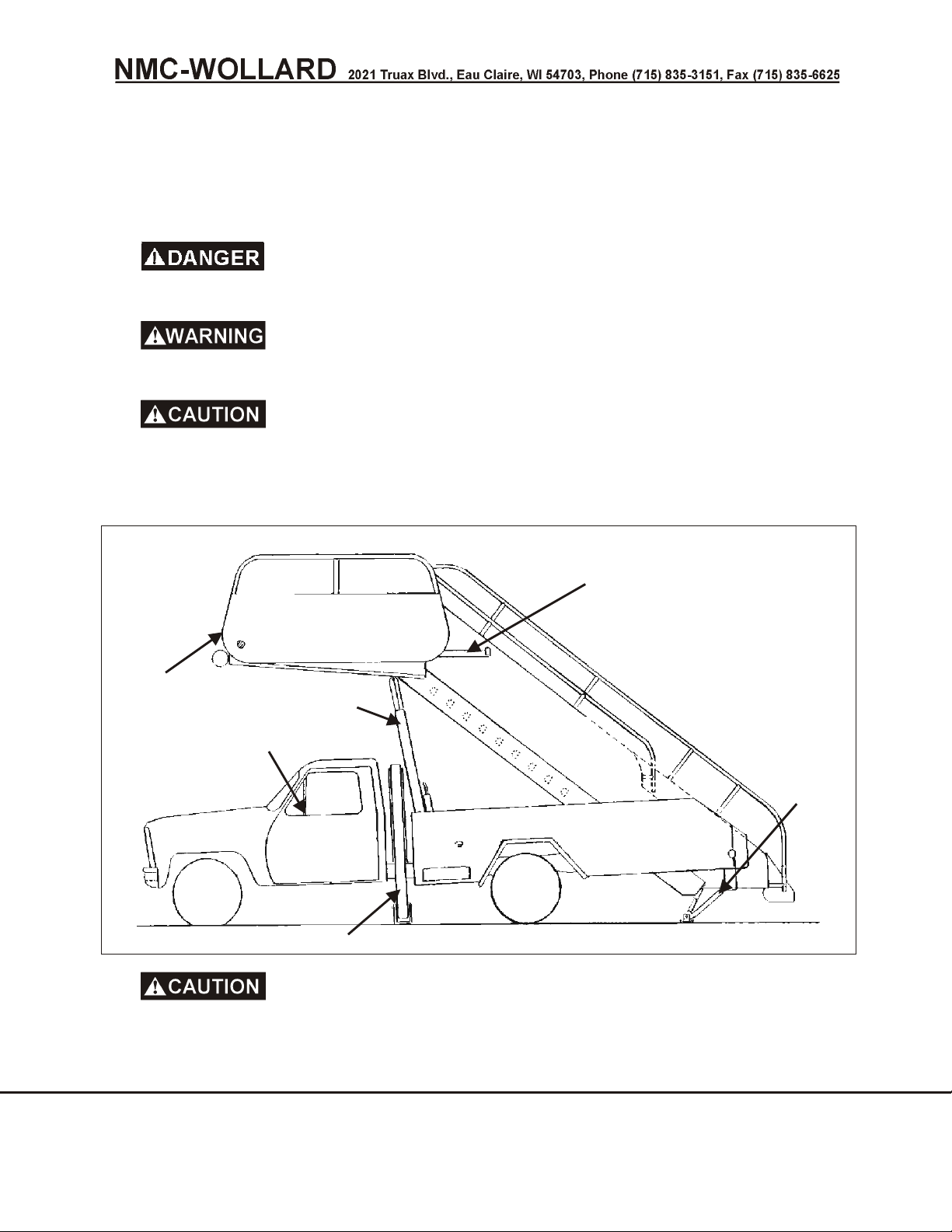
INSIDE LOWER STAIR
E
INSIDE
D
BOTH SIDES
A
ON DASH
C
B
B
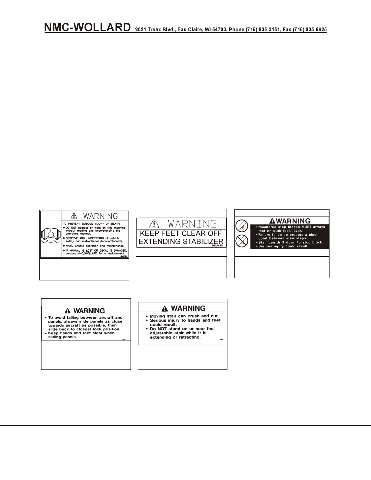
For your pro tec tion, read all safety de cals on the ma chine and in this
man ual. Re place any miss ing or il leg i ble de cals by or der ing the part num bers shown
on the safety de cals page.
CHAPTER 1 GENERAL INFORMATION & OPERATION INSTRUCTIONS SEPTEMBER 30, 2008
1 DESCRIPTION PAGE 1
Page 30
Truck Mounted Passenger Stair TMPS-200 Manual No. 307559
1.2 SAFETY DECALS
1.2.1 Safety Sign Care
• Keep Safety Signs Clean And Legible At All Times.
• Replace Safety Signs That Are Missing Or Have Become Illegible.
• Replaced Parts That Displayed A Safety Sign Should Also Display
The Current Sign.
• Safety Signs Are Available From The Manufacturer.
1.2.2 How to Install Safety Signs
• Be Sure That The Installation Area Is Clean And Dry.
• Remove The Smallest Portion Of The Split Backing Paper.
• Align The Decal Over The Specified Area And Carefully Press The
Small Portion With The Exposed Adhesive Backing In Place.
• Remove Second Backing And Press Remaining Decal In Place.
DECAL A.
PART NO. 305732
DECAL D.
PART NO. 304327
DECAL B.
PART NO. 562A439
DECAL E.
PART NO. 304335
DECAL C.
PART NO. 304272
SEPTEMBER 30, 2008 CHAPTER 1 GENERAL INFORMATION & OPERATION INSTRUCTIONS
PAGE 2 1 DESCRIPTION
Page 31

Truck Mounted Passenger Stair TMPS-200 Manual No. 307559
1.3 GENERAL SAFETY PRECAUTION
All per son nel who will han dle, in stall, use or ser vice this ma chine are re quired to read
and un der stand the rec om mended prac tices and safety pre cau tions in this man ual. If
there is a ques tion that can not be an swered sat is fac to rily by a su per vi sor, con tact the
Cus tomer Ser vice De part ment at NMC-Wollard, Inc.
There are in her ent haz ards as so ci ated with the op er a tion and ser vic ing of this
ma chine. For your pro tec tion please read and un der stand the fol low ing pre cau tions
be fore op er at ing or ser vic ing this ma chine.
• Never ap proach over head power lines or ca bles with any part of your
ma chine. Con tact with or get ting close to any power lines or ca bles can re sult
in elec tro cu tion.
• Fuel va pors cre ate fire and ex plo sion haz ards. Do not al low any open flame,
smok ing ma te ri als or other po ten tial ig ni tion sources near fuel or the fuel
sys tem.
• Never op er ate with out all cov ers, shields and guards in place. Body, hair or
cloth ing can be come en tan gled in ex posed, mov ing parts and can cause
se ri ous in jury or death.
• Keep hands, loose cloth ing, long hair and loose jew elry away from mov ing
parts. You may be come en tan gled in mov ing parts that can cause se ri ous
in jury or death.
• Per form lock out/tagout pro ce dures be fore ad just ing, lu bri cat ing, clean ing or
oth er wise ser vic ing. Fail ure to do so could re sult in un ex pected startup and
could cause se ri ous in jury or death.
• Use seat belts, ap proved head gear, eye pro tec tion and other pro tec tive
equip ment as re quired by fed eral, state, lo cal or em ployer reg u la tions.
• Do not op er ate or ser vice this ma chine while un der the in flu ence of any drugs or
al co hol.
• Do not in dulge in stunt driv ing or other reck less op er a tion.
• Limit travel speed. Ground conditions, congestion, slope, location of
personnel and other factors increase risk of collision or injury to personnel.
• Op er a tor must be pres ent while this ma chine is in use.
• Cal i for nia Prop o si tion 65 Warn ing: Die sel en gine ex haust and some of its
con stit u ents are known to the State of Cal i for nia to cause can cer, birth
de fects, and other re pro duc tive harm.
CHAPTER 1 GENERAL INFORMATION & OPERATION INSTRUCTIONS SEPTEMBER 30, 2008
1 DESCRIPTION PAGE 3
Page 32

Truck Mounted Passenger Stair TMPS-200 Manual No. 307559
• To min i mize risk of se ri ous in jury or death, fol low these hy drau lic ser vic ing
pre cau tions:
• Fol low all nec es sary lock out/tagout pro ce dures.
• Hy drau lic sys tems have re sid ual, stored pres sure. Re lieve all pres sure
from the hy drau lic sys tem be fore ser vic ing.
• Al low fluid to cool be fore work ing on sys tem.
• Hy drau lic fluid es cap ing un der pres sure can have suf fi cient force to
en ter eyes and pen e trate skin. If fluid gets in eyes or skin, flush with
large quan ti ties of wa ter and seek med i cal at ten tion.
• Wear eye pro tec tion when ser vic ing hy drau lic com po nents or
sys tems.
• Keep all hoses and con nec tions in good ser vice able con di tion. Check
be fore start-up and pe ri od i cally dur ing op er a tion.
• Do not in ves ti gate for leaks with hands. Use a large piece of
card board.
• To min i mize risk of fire or ex plo sion, fol low these bat tery ser vic ing safety
pre cau tions:
• Sul fu ric bat tery acid is poi son ous. Avoid breath ing bat tery fumes.
• Bat tery acid is strong enough to burn skin and cause blind ness if splashed
into the eyes. Pro tect eyes and skin from con tact. In the event of con tact with
bat tery acid, im me di ately rinse in large amounts of wa ter. Ob tain med i cal
care if the eyes are burned.
• Bat tery gas can ex plode. Keep sparks and flame away from bat tery.
• Never check bat tery charge by plac ing a metal ob ject across the
bat tery posts. A spark will oc cur and cause pos si ble ex plo sion. Use a
volt me ter or hy drom e ter.
• To avoid falls and in jury, stand only on ar eas con structed with “gripstrut” or
an other skid re sis tant sur face. Keep these sur faces in ser vice able con di tion.
• Never make any al ter ations or mod i fi ca tions to this equip ment in clud ing
dis abling safety de vices or in ter locks.
• Be fore start ing re pairs which do not re quire bat tery power, al ways turn off the
key switch, then dis con nect the bat tery con nec tor from the bat tery to pre vent
ac ci den tal short cir cuit.
• Be cer tain area is clear of peo ple and other equip ment be fore start ing
op er a tion.
• Keep ma chine clear of for eign ob jects and clean of grease/oil and other
lu bri cants.
SEPTEMBER 30, 2008 CHAPTER 1 GENERAL INFORMATION & OPERATION INSTRUCTIONS
PAGE 4 1 DESCRIPTION
Page 33

Truck Mounted Passenger Stair TMPS-200 Manual No. 307559
Fail ure to heed could re sult in se ri ous per sonal in jury or death.
In ad di tion to these gen eral safety pre cau tions you will find spe cific safety
mes sages em bed ded in the Op er ating and Main te nance Chap ters of this
man ual. Please re view them for your pro tec tion.
CHAPTER 1 GENERAL INFORMATION & OPERATION INSTRUCTIONS SEPTEMBER 30, 2008
1 DESCRIPTION PAGE 5
Page 34

Truck Mounted Passenger Stair TMPS-200 Manual No. 307559
1.4 EQUIPMENT DESCRIPTION
1.4.1 Intended Usage
The Wollard Model TMPS-200 is a mobile aircraft boarding facility for large
transport-type aircraft. The height of the stair is hydraulically adjustable and will
accommodate aircraft having door thresholds ranging from approximately
101-200 inches (256 cm to 508 cm) above the ground.
The design is not intended to service any other type of vehicle or any type of
structure.
1.4.2 Description of the Passenger Stair
The entire stair assembly is mounted on a heavy-duty commercial chassis with
dual rear wheels. Special equipment, steel supporting structures, electrical and
hydraulic components have been installed on the basic vehicle. Some minor
alterations have also been made to the vehicle's chassis and body.
The passenger stair consists of these major components: a truck section, a main
stair section (the stationary unit), and a main support frame which supports the
main stair section. The main support frame is equipped with a hydraulically
actuated upper section. An independent hydraulic system supplies hydraulic
power to operate the adjustable stair unit and stabilizers. The hydraulic functions
are controlled by electrical switches installed in the truck cab.
1.4.3 Reserved For Future Use
1.4.4 Hydraulic Hand Pump
Operates stabilizers when there is no power to drive main hydraulic pump.
1.4.5 Truck Section
The truck section consists of a heavy-duty commercial truck chassis having a
gross vehicle weight of 11,000 pounds (4,990 kg). An automatic transmission is
standard equipment (a 5-speed manual transmission is optional). A hydraulic
pump with a magnetic clutch controlled by the master switch is mounted in the
engine compartment and is driven by the engine serpentine belt.
1.4.6 Lighting
For night operation, the following lighting is provided:
• lighting in the inner panel at each stair tread
• illumination of the bottom step
JANUARY 31, 2014 CHAPTER 1 GENERAL INFORMATION & OPERATION INSTRUCTIONS
PAGE 6 1 DESCRIPTION
Page 35

Truck Mounted Passenger Stair TMPS-200 Manual No. 307559
• ground illumination in vicinity of bottom step
• ground illumination on each main stabilizer
• top platform light in the platform end skin of the adjustable section.
Stair lighting is controlled by a switch located on the dash in the truck cab.
Stabilizer illumination lights are controlled by a single proximity switch actuated
by the left forward stabilizer.
Stabilizer illumination lights (one at each forward stabilizer) are controlled by a
single proximity switch actuated by the left forward stabilizer.
1.4.7 Stabilizers
Two heavy-duty hydraulically actuated stabilizers are attached to the frame stair
support immediately behind the cab. Smaller extendible stabilizers are mounted
under the stairs at the rear. Both sets of stabilizers are actuated by double-acting
hydraulic cylinders and are controlled by a single lever on the cab control
console.
NOTICE! When the “STABILIZERS NOT RETRACTED” indicator is ON, the
stabilizers are not fully retracted and the stair can not be driven.
If the sta bi liz ers are in the down po si tion the engine will shut down if move ment
is at tempted.
1.4.8 Main Support Frame
The main supporting frame is constructed of welded steel members and is
fastened to the truck chassis. This frame extends from behind the cab to the rear
of the chassis.
1.4.9 Forward Support Frame (A-Frame)
The forward support frame is mounted vertically on the main support frame and
supports the upper end of the main stair section. The frame is a welded tubular
structure. The upper section is a telescoping structure capable of extending the
height of the support frame. Extension and lowering is provided by a hydraulic
cylinder. A solenoid-actuated lock lever fitted into a ratchet rack provides positive
locking of the telescoping structure.
1.4.10 Stair Section
The stair section is composed of a main section (stationary unit) and an
adjustable section (telescoping unit). Both are similar in construction and are
made of riveted aluminum alloy sheet on welded steel frames. On standard
CHAPTER 1 GENERAL INFORMATION & OPERATION INSTRUCTIONS SEPTEMBER 30, 2008
1 DESCRIPTION PAGE 7
Page 36

Truck Mounted Passenger Stair TMPS-200 Manual No. 307559
models, the stair treads, intermediate platform, and upper platform are surfaced
with aluminum alloy diamond-plate treads. Rubber treads over aluminum alloy
surfaces can be supplied as an alternate to the diamond plate.
1.4.11 Main Section (Stationary Unit)
The main stair unit is built on a frame of structural steel channels. Side panels of
fabricated sheet aluminum are riveted to this frame. Two wheels are attached on
each side of the upper part of the frame. The adjustable section's main
longitudinal support channels ride over these wheels to provide the telescoping
feature.
The lowest step (flip step) is mounted on pivots between the side panels. This
step may be flipped up between the side panels to allow sufficient ground
clearance when moving the stair. There are fourteen step treads in the main
section. The uppermost tread plate is deeper and serves as an intermediate
platform between the main section and the adjustable section.
Installed within the main section is a positive-displacement single-acting hydraulic
cylinder. This cylinder is attached to a cross member at its lower end, and the
upper end attaches to the adjustable section. This is the lift cylinder that
hydraulically adjusts the stair section.
1.4.12 Adjustable Section (Telescoping Unit)
The adjustable stair unit is built on a welded-steel frame composed of two
parallel/longitudinal channel members. The open sides of the channels oppose
each other and telescope over the four support wheels attached to the main
section. Steel angles welded to the underside of the channels are notched in
such a way that when solenoid-actuated latches are engaged in the notches, the
section is precisely positioned for any of ten stair heights (See operation
instruction). There are ten steps.
The top platform is a riveted assembly of aluminum alloy components. It is
supported by two fabricated channel members installed longitudinally. On the aft
end of the platform, a steel cross member is attached to these supports. This
cross member has a lug on its aft side to which the upper end of the hydraulic lift
cylinder is attached. When hydraulic power is applied to the cylinder, a piston
extends the adjustable stair section. A neoprene rubber bumper is attached to
the forward edge of the platform to protect aircraft.
Movable handrails are on either side of the top platform. These are adjustable
fore and aft and can be locked in position. The forward edges of these panels are
padded to protect aircraft.
SEPTEMBER 30, 2008 CHAPTER 1 GENERAL INFORMATION & OPERATION INSTRUCTIONS
PAGE 8 1 DESCRIPTION
Page 37

Truck Mounted Passenger Stair TMPS-200 Manual No. 307559
1.4.13 Hydraulic Reservoir
The hydraulic reservoir (tank) is installed within the main frame under the main
stair section near the forward end. Capacity is 15 U.S. gallons (57 liters). A sight
gauge is provided to check the oil level.
1.4.14 Side Panels
Steel side panels cover each side of the unit aft of the cab. The side panels have
fenders for the dual rear wheels and provide protection for the stair structure.
1.4.15 Canopy
An optional canopy is available for the protection of boarding or disembarking
passengers.
1.4.16 Other Features
Other features of the truck section include an automatic transmission, a safety
plate glass window mounted in the cab roof over the operator's seat, and a
spotlight under the upper platform for night operation.
Index numbers are at each step position to enable the operator to pre-position
the stair section prior to final positioning to aircraft door threshold. The index
numbers are also lighted for night operation.
CHAPTER 1 GENERAL INFORMATION & OPERATION INSTRUCTIONS SEPTEMBER 30, 2008
1 DESCRIPTION PAGE 9
Page 38

Truck Mounted Passenger Stair TMPS-200 Manual No. 307559
1
2 OPERATION
Read and un der stand the Owner’s Man ual be fore op er at ing this
ma chine. Fail ure to fol low the safety in struc tions could re sult in se ri ous in jury or death.
Limit travel speed. Ground conditions, congestion, slope, location of
personnel and other factors increase risk of collision or injury to personnel.
To prevent serious injury, all riders must ride in a passenger seat with
the safety belt fastened.
Always approach turns slowly and carefully. When approaching blind
corners or steering around obstructions, reduce speed and proceed cautiously.
Be extremely alert during hazardous operating conditions. Operating
conditions can change as work progresses and as weather changes.
2.1 PRE-OPERATION
All controls are in the truck cab and are clearly marked. The following procedures are
recommended for operating the unit. First become familiar with the controls and
switches described in Section 1 of this chapter. No instructions are given for operation
of the basic truck because this is covered in the owner's handbook supplied by the
truck manufacturer (Ford).
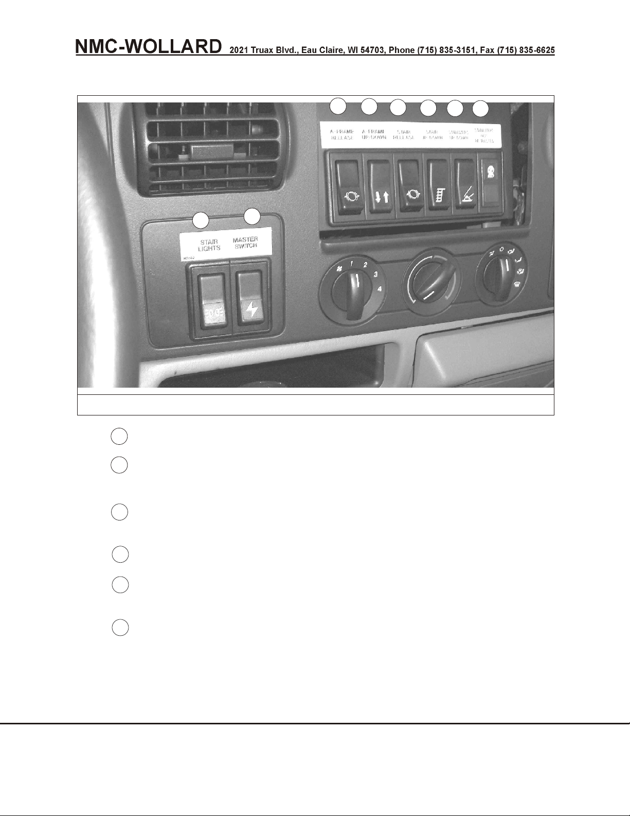
All electrical switches for operating the stair are on the truck dash as shown in Figure 1
and are discussed below. A window installed in the cab roof allows overhead viewing of
the stair.
MASTER SWITCH - controls power to all electrical control circuits;
specifically, the hydraulic pump magnetic clutch, the A-Frame Release, Stair
Release, Stair Lights, A-Frame Up/Down, Stair Extend/Retract and Stabilizers
Up/Down. Placing the master switch to "OFF" removes power from the stair and
A-Frame release solenoids, preventing the corresponding lock levers from being
energized to the unlocked condition. With master switch Off, the stair and
A-frame remain locked by lock levers and will not lower or retract even if the Stair
Retract or A-Frame Down switches are actuated.
NOTE: Turn the MASTER SWITCH “on” to enable lock lever (pawl) circuit and stair
lighting when required.
CHAPTER 1 GENERAL INFORMATION & OPERATION INSTRUCTIONS JANUARY 31, 2014
2 OPERATION PAGE 1
Page 39
Truck Mounted Passenger Stair TMPS-200 Manual No. 307559
2
1
3
4
5
6
7
8
2
3
4
567
FIGURE 1. IN CAB CONTROL SWITCHES
STAIR LIGHTS switch - operates tread lights and spotlight.
A-FRAME RELEASE switch - release A-Frame lock lever while lowering
A-Frame.
A-FRAME UP/DOWN switch - operates A-frame hydraulic valve to control
hydraulic cylinder for precise positioning of the platform.
STAIR RELEASE switch - release stair lock lever while lowering stair.
STAIR EXTEND/RETRACT switch - operates hydraulic control valve to control
flow of hydraulic oil to stair extend/retract hydraulic cylinder.
STABILIZER UP/DOWN switch - operates hydraulic valve to control flow of
hydraulic oil for stabilizer up and down operation.
JANUARY 31, 2014 CHAPTER 1 GENERAL INFORMATION & OPERATION INSTRUCTIONS
PAGE 2 2 OPERATION
Page 40
Truck Mounted Passenger Stair TMPS-200 Manual No. 307559
8
9
NOTE: All hydraulic stair functions are manually activated by switches in the cab
which control hydraulic solenoid valves.
IMPORTANT: The sta bi liz ers are in ter locked to pre vent mov ing the unit if the
sta bi liz ers are in the down po si tion. The engine will shut down if shifted out of park or
neutral.
There is a flashing "STABILIZER NOT RETRACTED" indicator lamp to alert
the operator movement can not be attempted until they are retracted.
NOTICE! When the “STABILIZERS NOT RETRACTED” indicator is ON, the stabilizers
are not fully retracted and the stair can not be driven.
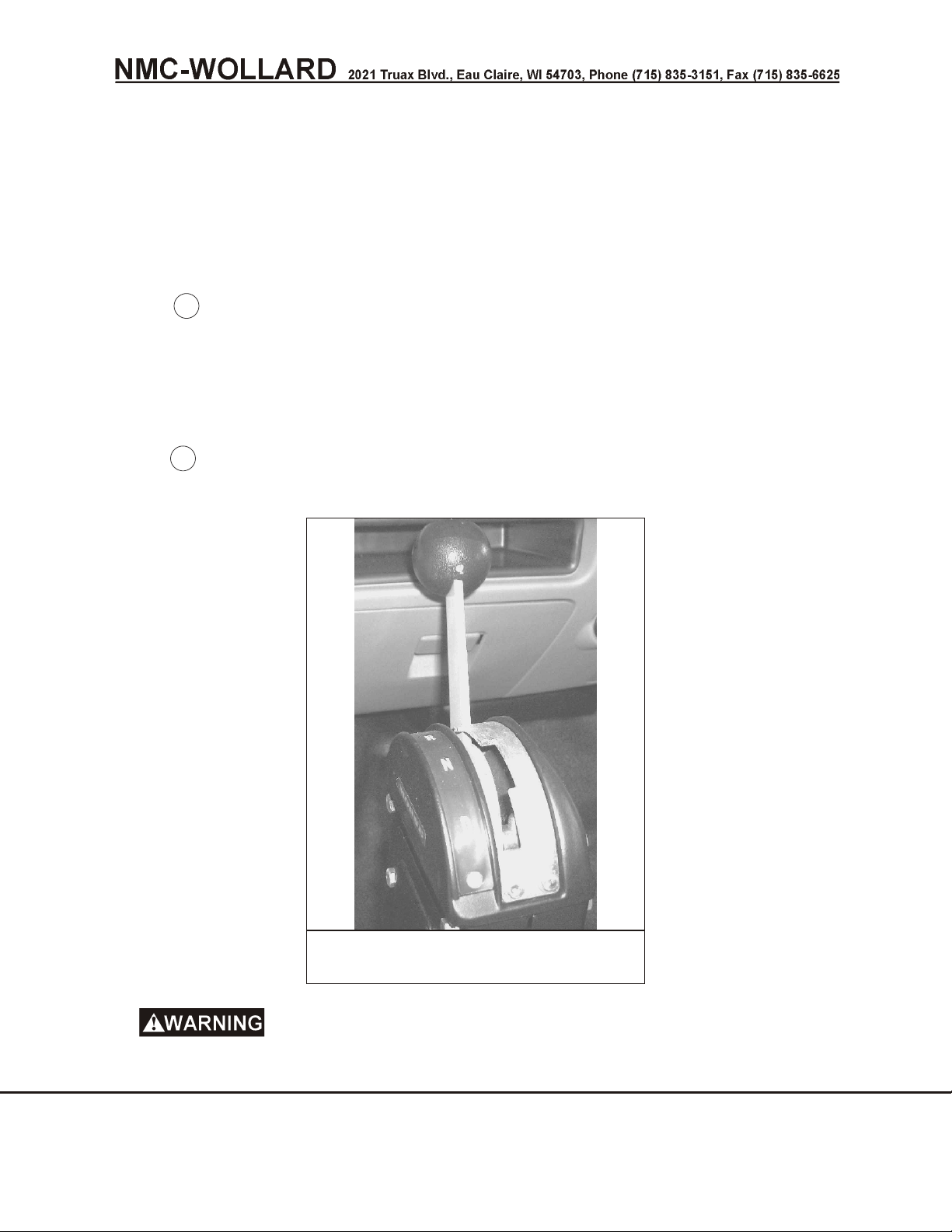
Shifter - optional floor mounted shifter with P-R-N-D to shift transmission. See
figure 2.
FIGURE 2. OPTIONAL FLOOR
MOUNTED SHIFTER
Always apply park brake when shifted to neutral (N). Unintended
movement could result in persons falling or being crushed.
CHAPTER 1 GENERAL INFORMATION & OPERATION INSTRUCTIONS JANUARY 31, 2014
2 OPERATION PAGE 3
Page 41

Truck Mounted Passenger Stair TMPS-200 Manual No. 307559
Preparation for Service
The unit is lubricated, adjusted, and tested at the factory prior to shipment. It is then
prepared for shipment (See Section 4 of this chapter).
Before placing the unit in service, perform the commissioning
preparations. Failure to do so will cause the passenger stair to be unsafe to use,
operate, or service and could cause serious injury or death.
2.2 DAILY INSPECTION
Before putting the unit into service and each day before operating the unit, always walk
around the unit and make the following checks:
2.2.1 Hydraulic System
1. Look for fluid leaks on the ground and on hydraulic components. Check
hydraulic hose and fitting connections for leaks and hose condition.
2. Check level of hydraulic oil by observing the sight gauge on hydraulic
reservoir. The correct fluid is MOBIL DTE-13. In extreme cold, use Mobil
Aero HFA (MIL H-5606). IMPORTANT! Check hydraulic oil level with
cylinders completely lowered or overfilling might result, causing damage
to the hydraulic system.
2.2.2 Stair Unit
1. Check all critical fastener connections for security.
2. Check that the stabilizer pads, links, and pivots are present and
functional and that the mounting hardware is secure.
3. Remove any foreign objects from stairs and clean any grease, oil or other
lubricants from stairs.
4. Check that the stair handrail is fastened securely to the stairs.
5. Inspect the wheels at the lower edge of the platform handrails (wing
panels). If the wheels are cracked or damaged they must be replaced. Be
sure all fasteners and retaining brackets to keep the wheels on the guide
angle are in place and tight. Check that the notched track is tightly
attached to the panel.
6. Check that the platform handrails (wings) slide freely. Check that the
latch works properly and that the handrails lock in the detents securely. If
the handrails do not slide freely or the latch does not work properly,
adjustment is required before the stair unit can be put into service.
SEPTEMBER 30, 2008 CHAPTER 1 GENERAL INFORMATION & OPERATION INSTRUCTIONS
PAGE 4 2 OPERATION
Page 42

Truck Mounted Passenger Stair TMPS-200 Manual No. 307559
To prevent hand rails from falling away from the stair unit and
creating a safely hazard, you must inspect and service them as described in this
manual.
7. Check that all the flip step pivot hardware is present and tight. Flip the
step up for transporting.
8. If so equipped, check the fire extinguisher for adequate charge.
2.2.3 General Chassis Check
1. Check truck chassis and engine in accordance with manufacturers
instructions
2. Observe that tires are properly inflated.
Regularly check tires and wheels for proper tire inflation or loose
wheel studs/nuts. Dual wheel sets must have equal inflation in both tires to
prevent tire overloading. Wheel or tire failure could result in loss of vehicle
control.
2.2.4 Electrical System
1. With the ignition switch on:
2. Check the fuel gauge for sufficient fuel for the day’s operation. Check the
instrument panel for low volts or low oil pressure and any other fault
indications.
3. Check that horn, windshield wipers, headlights, tail lights, stop lights,
backup lights and beacons are operational.
4. Turn on the Stair control Master Switch and switch on the Stair Lights
switch and check that the tread lights and spotlight are operational.
2.2.5 Operational Check
1. Start engine and allow to warm up at idle speed for a few minutes.
2. Check operation of brakes and power steering.
3. Check the raise/lower operation of stair lift and stabilizer cylinders, using
the control switches on the truck dash. Be sure there is sufficient
overhead clearance before raising stairs.
4. If all of the above checks are satisfactory, the unit is ready to service
aircraft. If trouble is discovered during any of the above checks, report the
problem to the proper maintenance personnel for correction before
further operation.
CHAPTER 1 GENERAL INFORMATION & OPERATION INSTRUCTIONS SEPTEMBER 30, 2008
2 OPERATION PAGE 5
Page 43
Truck Mounted Passenger Stair TMPS-200 Manual No. 307559
2.3 DRIVING THE UNIT
The stair must be fully retracted and the A-Frame fully lowered
whenever traveling and when not being used. Failure to do so could result in
overturned machine from wind or jet blast.
NOTICE! When the “STABILIZERS NOT RETRACTED” indicator is ON, the stabilizers
are not fully retracted and the stair can not be driven.
2.3.1 Interlocks
Interlocks
Ve hi cle will not drive with the sta bi liz ers even slightly down and red “Stabilizers
Not Retracted” in di ca tor illuminated. If you at tempt to move, the en gine will shut
down. Raise sta bi liz ers un til fully re tracted and the “Stabilizers Not Retracted”
in di ca tor turns off.
1. No high speed or stunt-like ma neu vers.
2. Rid ers only allowed if seated on passenger seat.
3. Use seat belts.
4. Use on re stricted air port roads and ramp ar eas only, not on pub lic roads
in any coun try.
5. No high speed turns, es pe cially when stairs are ex tended.
6. This is a high ve hi cle - al ways check your over head clear ance when
driv ing un der ob sta cles.
7. Brake gently when stairs are ex tended. Re strict driv ing speed to 5 mph
when stairs are ex tended.
2.4 SERVICING AIRCRAFT
NOTE: It is recommended to record the stair lock lever index positions for each type of
aircraft serviced, after determining this on the first application. There are index
numbers at the stop block locations under the adjustable stair section on the right side.
Use these settings thereafter. The stair lock lever (a pivoting pawl) and markers are
visible through the roof window. Use these settings before approaching the aircraft in
the future to lessen the possibility of error or damage.
Moving stair can crush and cut hands and feet. Do not stand on or
near the adjustable stair while it is extending or retracting.
1. Drive the unit to the aircraft to be serviced (To approx 15 feet away from
the aircraft).
SEPTEMBER 30, 2008 CHAPTER 1 GENERAL INFORMATION & OPERATION INSTRUCTIONS
PAGE 6 2 OPERATION
Page 44

Truck Mounted Passenger Stair TMPS-200 Manual No. 307559
2. Leave the engine idling, place the transmission in neutral and set the
parking brake.
3. Switch ON the MASTER SWITCH. Hold the A-FRAME UP/DOWN switch
UP or DOWN as instructed in step 4 or 5 and to position the A-Frame at
its center position.
4. To raise the A-Frame, hold the A-FRAME UP/DOWN switch UP. The
A-Frame has rigid “ratchet teeth” welded to the frame which will “ratchet”
past the pivoting A-Frame lock lever during raising. Then the A-Frame
must be lowered down, against the first available ratchet tooth to securely
lock the position during operation.
5. To lower the A-Frame, momentarily press the A-FRAME UP/DOWN
switch to UP and relieve stair load from the A-Frame lock lever. Then
press the A-FRAME RELEASE switch and hold while pressing the
A-FRAME UP/DOWN switch DOWN. Release the A-FRAME RELEASE
switch and A-FRAME UP/DOWN switch when the A-Frame reaches the
required position.
6. Hold the STAIR EXTEND/RETRACT switch to the EXTEND position
(This is assuming it is in the full retracted position) and adjust the stair
height to the door sill height to be serviced and consider the following. If
loading the aircraft, the fuselage will lower as much as several inches,
dependent on aircraft; so position the platform far enough below the door
sill that the door will not lower onto the platform and become damaged. If
unloading, the aircraft will rise and it is safe to position the platform “even”
with the door sill, allowing the door to move away from the platform.
7. The adjustable stair has “stop blocks” welded to the structure which slide
past the pivoting stair lock lever while extending. After extending, the stair
must be retracted against the first available stop block to securely lock
the stair in position during operation. This will also align the steps
properly.
Numbered stop blocks must always rest on stair lock lever.
Failure to do so creates a pinch point between stair steps and risk of serious
injury to feet if stairs drift down to stop block.
8. As necessary adjust the A-Frame. It allows for fine adjustment of stair
height/door sill adjustment. Be careful when lowering, as the stair will tilt
toward the aircraft and contact/damage could occur. Now the passenger
stair platform should be positioned at the correct service door sill height,
but not be in contact with the aircraft
CHAPTER 1 GENERAL INFORMATION & OPERATION INSTRUCTIONS SEPTEMBER 30, 2008
2 OPERATION PAGE 7
Page 45
Truck Mounted Passenger Stair TMPS-200 Manual No. 307559
9. Release the parking brake and carefully idle the unit forward to the
aircraft and make soft contact of the rubber platform bumper with the
aircraft. Use the overhead spotlight as necessary for night operation.
10.
VERY IMPORTANT: Do not adjust the stair height once in contact with
the aircraft. If further adjustment is required, carefully back away and
re-start this procedure.
11. Place transmission shifter to neutral position and set the parking brake.
12. Hold the A-FRAME UP/DOWN switch UP to move the stair away from the
aircraft until approximately 3 inches of clearance is achieved.
13. Press the STABILIZER UP/DOWN switch DOWN and hold until all
stabilizers are fully lowered. “STABILIZER NOT RETRACTED” indicator
light will illuminate.
To avoid crushing injury to feet, stay clear of stabilizers.
14. Hold the A-FRAME UP/DOWN switch UP to allow the pressure to be
taken off the rigid ratchet tooth. Hold the A-FRAME RELEASE switch
and lower the A-Frame until it is almost in contact with the aircraft.
Release the A-FRAME RELEASE switch and lower the A-Frame lock
lever against the rigid ratchet tooth.
15. Switch the engine OFF. For night time operation, turn the ignition switch
to ON (leave power on) in order to power the stair lights. If the lights will
be used for more than 30 minutes, do not turn the engine OFF.
16. Lower the flip step at the bottom end of the stair. Climb the stair to the
platform and release the appropriate wing panel lock by pushing down on
the latch handle. Move the panel back to the full open position. Stand as
far back of the panels as possible so you are still protected by the wing
panels if you should fall. Now the aircraft door may be opened and
stowed. Care must be taken to stay away from any open areas while the
wing panel is in the retracted position and the aircraft door is being
positioned. After opening the door, move the wing panels ahead, as close
to the aircraft as possible and be sure the panels lock in position by
engaging in the closest detent notch.
17. The wing panels must be as close to the aircraft (or loading bridge) as
possible. The space must be at a minimum so persons can not fall
through the opening.
18. Check that the wing panels are secure by being sure they will not move
when force is applied to them.
SEPTEMBER 30, 2008 CHAPTER 1 GENERAL INFORMATION & OPERATION INSTRUCTIONS
PAGE 8 2 OPERATION
Page 46

Truck Mounted Passenger Stair TMPS-200 Manual No. 307559
To avoid falling between aircraft and panels, always slide panels
as close towards aircraft as possible, then slide back to the closest lock position.
Keep hands and feet clear when sliding panels. Never leave panels retracted
when positioned at an aircraft. Failure to heed could result in serious injury or
death to yourself or others.
19. Exit from the stair.
2.5 DRIVING AWAY FROM AIRCRAFT
1. Climb the stair to the platform and release the appropriate wing panel
lock by pushing down on the latch handle. Move the panel back to the full
open position. Now the aircraft door can be closed. Care must be taken
to stay away from any open areas while the wing panel is in the retracted
position and the aircraft door is being positioned.
2. Exit from the stair. Raise the flip step at the bottom end of the stair.
3. Start the engine and raise the A-Frame to tilt the stair away from the
aircraft.
4. Press the STABILIZER UP/DOWN switch UP and hold until “STABILIZER
NOT RETRACTED" indicator goes off.
5. Release the parking brake, place transmission in reverse, and back the
unit a short distance from aircraft. Set park brake and place transmission
in neutral position.
6. Momentarily press the STAIR EXTEND/RETRACT switch to EXTEND
and relieve stair load from stair lock lever. Press the STAIR RELEASE
switch and hold. Press the STAIR EXTEND/RETRACT switch to
RETRACT and hold until the stair section is fully retracted. Just before it
reaches bottom, release the stair release switch. This will allow the lock
lever to slide into its proper position. Then release the STAIR
EXTEND/RETRACT switch.
7. Momentarily press the A-FRAME UP/DOWN switch UP and relieve stair
load from the A-Frame lock lever. Press the A-FRAME RELEASE switch
and hold. Press the A-FRAME UP/DOWN switch DOWN to fully lower the
A-frame. Release the A-FRAME RELEASE switch and A-FRAME
UP/DOWN switch after the A-Frame reaches its down position.
8. Back the unit away from the aircraft and drive it to it’s proper place for
storage.
CHAPTER 1 GENERAL INFORMATION & OPERATION INSTRUCTIONS SEPTEMBER 30, 2008
2 OPERATION PAGE 9
Page 47

Truck Mounted Passenger Stair TMPS-200 Manual No. 307559
2.6 EMER GENCY PRO CE DURES
2.6.1 Using the Optional Hand Pump
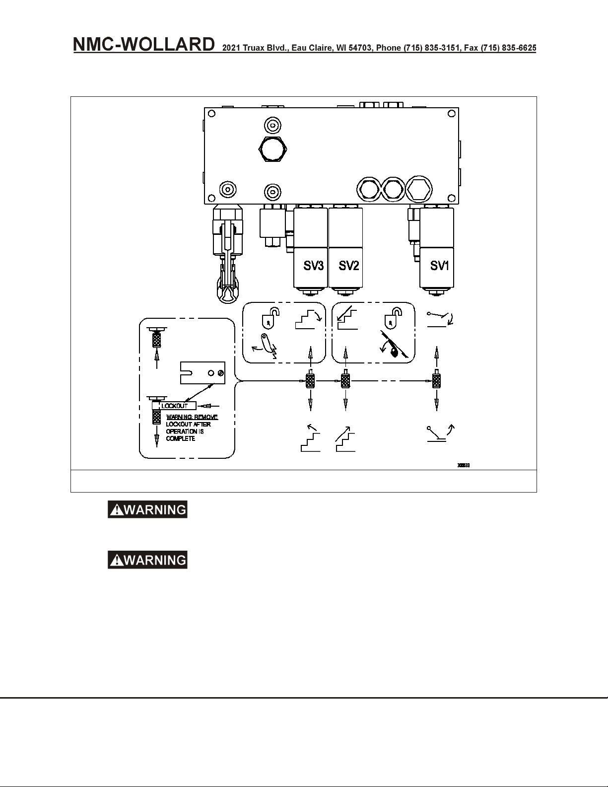
1. A man u ally op er ated hy drau lic pump is sup plied on the hy drau lic
man i fold. The pump per mits rais ing or low er ing the stair and sta bi liz ers
man u ally in the event of a fail ure of the en gine or hy drau lic sys tem.
2. The over ride knob on the ap pro pri ate hy drau lic so le noid valve must be
pushed in or pulled out and held out by in sert ing the lock tool be hind the
knob for manual operation. See fig ure 1. The tool is at tached to the valve
with a re tain ing chain. Af ter this is done, the man ual pump can be
op er ated.
VERY IMPORTANT: This lock out tool must be removed when manual
operation is completed.
3. Move the wing panel back, close aircraft door and raise the flip step as
instructed in 2.5
SEPTEMBER 30, 2008 CHAPTER 1 GENERAL INFORMATION & OPERATION INSTRUCTIONS
PAGE 10 2 OPERATION
Page 48
Truck Mounted Passenger Stair TMPS-200 Manual No. 307559
FIGURE 1. EMERGENCY HAND OPERATING HYDRAULICS
Be sure that all per sons are clear of the stair unit and away from
pos si ble pinch points while low er ing or rais ing the stair.
Num bered stop blocks must al ways rest on stair lock le ver.
Fail ure to do so cre ates a pinch point be tween stair steps and risk of se ri ous
in jury to feet if stairs drift down to stop block.
4. Pull the red over ride knob on the stabilizer valve labeled SV1 and insert
the slotted lock tool under the knob to keep it extended. Operate the
pump with the handle until the stabilizers are raised enough to clear the
ground. Then remove the tool from under the knob.
CHAPTER 1 GENERAL INFORMATION & OPERATION INSTRUCTIONS SEPTEMBER 30, 2008
2 OPERATION PAGE 11
Page 49

Truck Mounted Passenger Stair TMPS-200 Manual No. 307559
5. Be careful that the stair unit can not roll toward the aircraft and release
the parking brake. Chock ahead of the wheels if necessary. Roll or tow
the stair unit away from the aircraft. When parked, reapply the parking
brake.
6. Pull the red over ride knob on the stair valve labeled SV2 and insert the
slotted lock tool under the knob to keep it extended.
7. Operate the pump with the handle to extend the stair slightly and relieve
the pressure from the stair lock lever.
8. With the ignition and master switches on, have a helper hold the STAIR
RELEASE switch to release the stair lock lever. Then remove the tool
from under the valve over ride knob. Push the knob in and allow the stair
to retract by gravity.
9. If emer gency man ual op er a tion is re quired to lower the stair, and
elec tri cal power is not avail able, a sec ond per son will be re quired to hold
the stair lock re lease le ver down while the hand pump is op er ated.
Have your helper op er ate the stair lock le ver with a stick to
pre vent plac ing hands or body in un safe lo ca tions where se ri ous in jury could
oc cur as the stair low ers.
2.7 SERVICING LOADING FACILITIES OTHER THAN AIRCRAFT
Whenever the stair is positioned to a loading facility (such as a loading bridge) it is likely
that there will be a significant difference in the loading access area compared to the
width of the stair. You must install barriers or railings that conform to OSHA
specifications and regulations to restrict the opening to the width of the stair wings.
SEPTEMBER 30, 2008 CHAPTER 1 GENERAL INFORMATION & OPERATION INSTRUCTIONS
PAGE 12 2 OPERATION
Page 50

Truck Mounted Passenger Stair TMPS-200 Manual No. 307559
This Page Intentionally Blank
CHAPTER 1 GENERAL INFORMATION & OPERATION INSTRUCTIONS SEPTEMBER 30, 2008
2 OPERATION PAGE 13
Page 51

Truck Mounted Passenger Stair TMPS-200 Manual No. 307559
3 SPECIFICATIONS AND CAPABILITIES
3.1 AIRCRAFT SERVICING CAPABILITY - 2005 & LATER
All Aircraft having doorsill heights ranging from 100” (254cm) to 200” (508cm).
3.1.1 Stair Capacity
Platform ...............900 lbs. (409 kg) uniformly distributed load
Each Step ...............................200 lbs.
3.1.2 Height Range
Low Position ..........................100 in. (254 cm)
High Position..........................200 in. (508 cm)
3.1.3 Dimensions
Nominal tread depth......................10.05 in. (26 cm)
Nominal tread width (lower section) ...............42 in. (107 cm)
Nominal tread width (upper section) ..............47 in. (119 cm)
Top platform width .......................64 in. (163 cm)
Top platform depth .......................84 in. (213 cm)
Intermediate landing depth ..................19.75 in. (50 cm)
Constant riser height ......................7.85 in. (20 cm)
3.1.4 Shipping Dimensions
Length .............................288 in. (7.32 m)
Width .............................90.7 in. (2.30 m)
Height .............................145 in. (368 cm)
Weight ..........................11,000 lbs. (4,990 kg)
3.1.5 Operator Controls
Indicators ..................power, stabilizers down, stair lights
Switches............power, stair lights, “A” frame and Stair interlocks
A-frame and Stair UP/DOWN and Stabilizers UP/DOWN
3.1.6 Vehicle (standard)
Ford F-350, V-8 engine, automatic transmission, 11,000 lbs. (4990 kg) GVW,
power steering
CHAPTER 1 GENERAL INFORMATION & OPERATION INSTRUCTIONS SEPTEMBER 30, 2008
3 SPECIFICATIONS AND CAPABILITIES PAGE 1
Page 52

Truck Mounted Passenger Stair TMPS-200 Manual No. 307559
3.1.7 Truck Chassis
Ford Series F-350, Type F37
Gasoline Engine ...............Ford 350 (5.4L) V8, Fuel injected
Diesel Engine (option) ...Triton Ford 6.0L (V8 engine block heater standard)
3.1.8 Brakes
Service .......................Self-adjusting, dual power
3.1.9 Cab
.............................F350 Super Duty
3.1.10 Electrical
Alternator.........................Motorcraft 95 ampere
Battery ................................650 CCA
3.1.11 Shock Absorbers
........................Heavy duty, front and rear
3.1.12 Steering
..............................Power steering
3.1.13 Transmission
............4R100 Heavy Duty Electronic Automatic 4-speed
3.1.14 Hydraulic System
Cylinders ..............................single stage
Valveselectric switch actuated
Pump ..............................engine driven
System pressure .....................1,200 psi (82.8 bars)
Strainer, on suction line ........................80 mesh
Hydraulic tank ...........................breather cap
Auxiliary pump .......................manually operated
3.1.15 Options and Accessories
Two-tone paint
Diesel engine
Outside controls
Keyless ignition
Electric auxiliary pump
SEPTEMBER 30, 2008 CHAPTER 1 GENERAL INFORMATION & OPERATION INSTRUCTIONS
PAGE 2 3 SPECIFICATIONS AND CAPABILITIES
Page 53

Truck Mounted Passenger Stair TMPS-200 Manual No. 307559
Rotating beacon
Hour meter
Morse control
Governor
Mico lever brake lock
Back-up alarm
Heavy-duty bumper/grill guard
Undercoating
Rustproofing
Rubberized stair treads and platforms
CHAPTER 1 GENERAL INFORMATION & OPERATION INSTRUCTIONS SEPTEMBER 30, 2008
3 SPECIFICATIONS AND CAPABILITIES PAGE 3
Page 54

Truck Mounted Passenger Stair TMPS-200 Manual No. 307559
This Page Intentionally Blank
SEPTEMBER 30, 2008 CHAPTER 1 GENERAL INFORMATION & OPERATION INSTRUCTIONS
PAGE 4 3 SPECIFICATIONS AND CAPABILITIES
Page 55
Truck Mounted Passenger Stair TMPS-200 Manual No. 307559
4 COMMISSIONING AND DECOMMISSIONING FOR OPERATION AND
SHIPPING
4.1 COMMISSIONING/DECOMMISSIONING FOR AIRPORT, CROSS COUNTY OR
SHIPPING
The unit has been thoroughly lubricated and tested before leaving the factory, but to
ensure against damage, certain components have been strapped, wedged, packaged,
or covered, and, if shipment was overseas, coated with preservatives.
Before placing the unit in service, perform the commissioning
preparations. Failure to do so will cause the passenger stair to be unsafe to use,
operate, or service and could cause serious injury or death.
4.2 TRUCK CHASSIS
Observe break-in procedures as recommended in owner manual delivered with
chassis by manufacturer.
4.2.1 Front Spring Lockouts
Figure 1
Front spring lockouts must be installed before unit is placed in operation and
must be removed for any cross-country travel. Front springs are locked out by
installing a spacer block between the axle and existing rubber pads on the frame.
1. Jack up front of truck to remove load from front springs.
2. Remove lockouts from their shipping position in glove box. Each lockout
kit consists of a steel spacer block, a plate, and two capscrews and
lockwashers.
3. Install lockout spacer blocks between rubber pads and frame as shown in
Figure 1 on the next page.
4. Lower truck front end and remove jack.
NOTE: The resulting ride should be quite firm.
CHAPTER 1 GENERAL INFORMATION & OPERATION INSTRUCTIONS SEPTEMBER 30, 2008
4 COMMISSIONING AND DECOMMISSIONING FOR OPERATION AND SHIPPING PAGE 1
Page 56
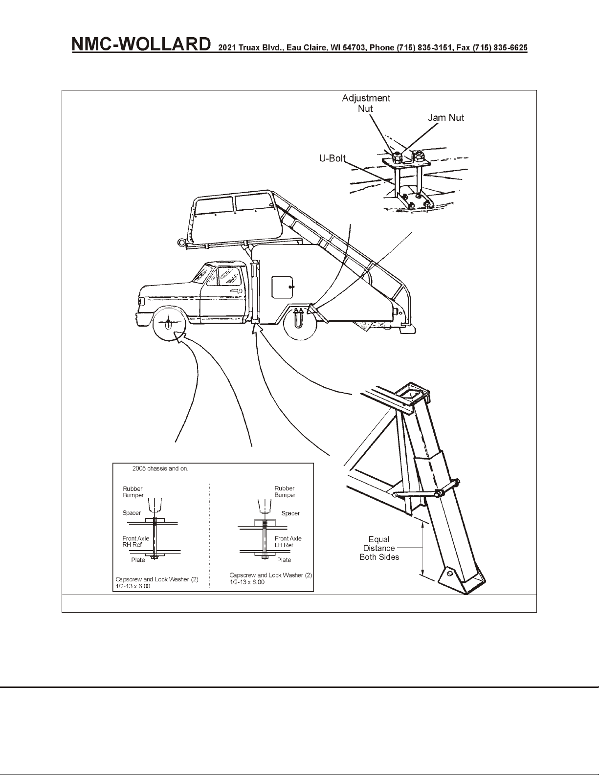
Truck Mounted Passenger Stair TMPS-200 Manual No. 307559
FIGURE 1. TRUCK PREPARATION
4.2.2 Rear Spring U-Bolts
Figure 1
Rear spring U-bolts (tie-downs) are shipped installed but not tightened. Prior to
operating at destination, adjust rear spring U-bolts as follows:
SEPTEMBER 30, 2008 CHAPTER 1 GENERAL INFORMATION & OPERATION INSTRUCTIONS
PAGE 2 4 COMMISSIONING AND DECOMMISSIONING FOR OPERATION AND SHIPPING
Page 57

Truck Mounted Passenger Stair TMPS-200 Manual No. 307559
1. Park vehicle on level surface.
2. Assure that front spring lockouts have been installed.
3. Raise adjustable stair to full extension. Lower A-frame fully.
4. Operate stabilizers to full extension.
5. Enter stair cavity to reach rear axle U-bolt adjustment nuts.
6. Alternately tighten adjustment nuts on each U-bolt until both front and
rear stabilizer pads appear to make firm contact with ground. Verify by
manually pulling out on the lower part of each front stabilizer or by kicking
the foot pad.
NOTE: It will be easier to tighten the nuts on the U-bolts if the stabilizers are
raised and the stairs are fully retracted to put maximum load on the rear springs.
7. Retract stabilizers.
8. Measure height of front stabilizer structure from ground on both sides of
truck.
9. If measurements are unequal, tighten U-bolts on high side until both
sides are even.
10. Continue tightening both U-bolts until the height of the frame has been
reduced by an additional ½" on each side.
11. Again check that both sides have the same measurement from the
ground at front stabilizer structure.
12. Extend stabilizers, and check that they contact the ground hard.
13. Retract stair, and make sure that all stabilizers are still in hard contact.
14. Tighten jam locknuts over rear axle U-bolt adjustment nuts.
4.3 INSTALLING THE HANDRAILS
4.3.1 Stair Handrails
Hand rails are marked to identify left hand and right hand
installation. Failure to install correctly is unsafe.
1. Remove strapping from handrails.
2. Inspect handrails.
a. Make sure the handrail support posts are secure on the handrail.
Tighten the center bolt if required.
CHAPTER 1 GENERAL INFORMATION & OPERATION INSTRUCTIONS SEPTEMBER 30, 2008
4 COMMISSIONING AND DECOMMISSIONING FOR OPERATION AND SHIPPING PAGE 3
Page 58

Truck Mounted Passenger Stair TMPS-200 Manual No. 307559
b. Check handrail for marks or scratches received during shipment. Use
a file to smooth any nicks that might cause injury. Use fine or medium
steel wool to polish surfaces.
3. The 1/4-28 handrail attaching screws are shipped installed on the stair.
Remove handrail attaching screws. Note location of the 1.00" and 1.25"
long screws.
4. Position handrail for installation. Check for proper alignment of screw
hole holes. Support posts can be moved slightly to align holes. If
necessary, use a rubber mallet to tap posts unto alignment.
5. Working down from the top handrail support post, secure handrail to
stairs using the 1/4-28 screws.
4.3.2 Platform Handrails (Wings)
The platform handrails are shipped completely assembled and strapped to the
platform deck.
1. Remove strapping and padding. Left and right handrails can be identified
by observing position of bumpers (forward) and notched adjustment
tracks (inboard).
2. Remove the rear stops from the lower tracks.
3. Using two people, place forward wheel of handrail onto lower track and
slide upper (adjustment) track into slots in slide blocks. Slide handrail
forward until rear wheel rests on lower track.
4. Install other platform handrail as described in step 3.
5. Re-install rear stops on lower tracks.
6. Slide handrails from stop to stop. Check for ease of operation and
security in detents. If necessary, adjust the slide blocks.
4.4 MISCELLANEOUS PREPARATION
4.4.1 Cleaning
1. Wash road dirt from stair sections and chassis.
4.5 FLOODLIGHT
1. Remove the protective covering from the floodlight under platform.
4.5.1 Movable Handrails
1. The handrails have been strapped in position. Remove the straps.
SEPTEMBER 30, 2008 CHAPTER 1 GENERAL INFORMATION & OPERATION INSTRUCTIONS
PAGE 4 4 COMMISSIONING AND DECOMMISSIONING FOR OPERATION AND SHIPPING
Page 59

Truck Mounted Passenger Stair TMPS-200 Manual No. 307559
4.5.2 Stabilizers
1. Each stabilizer is secured in the UP position. Remove straps.
4.5.3 Hydraulic Oil
1. Check level of hydraulic oil in reservoir. Correct level is at "FULL" mark
on sight gauge with all actuating cylinders retracted. Working capacity of
reservoir is 15 U.S. gallons (57 liters). See Chapter 2 for hydraulic oil
specifications.
4.5.4 Fastenings
1. Check all fastenings throughout the unit for tightness and security.
4.5.5 Operational Check
1. Operate the unit in all functional modes. Check for proper control
responses. Observe hydraulic fittings for leakage, etc.
IMPORTANT! Familiarize yourself with Section 1 and 2 before attempting to
operate the unit.
4.6 RECORD AIRCRAFT SERVICING DATA
It is recommended to record the stair lock lever index positions for each type of
aircraft serviced, after determining this on the first application. There are index
numbers at the stop block locations under the adjustable stair section on the right
side. Use these settings thereafter. The stair lock lever (a pivoting pawl) and
markers are visible through the roof window. Use these settings before
approaching the aircraft in the future to lessen the possibility of error or damage.
See 2 - 2.4.
4.7 SHIPPING THE UNIT
If the unit is to be shipped to another location, it should be properly prepared to
prevent damage. All component parts that were strapped or otherwise prepared
at the factory for initial delivery should again be prepared in a similar manner.
The front spring tie-downs should also be removed and the original rubber pads
installed. Loosen the rear spring tie-downs until sufficient spring action is
obtained. Store both front spring tie-down parts in appropriate locations so that
they may be installed at next using station.
CHAPTER 1 GENERAL INFORMATION & OPERATION INSTRUCTIONS SEPTEMBER 30, 2008
4 COMMISSIONING AND DECOMMISSIONING FOR OPERATION AND SHIPPING PAGE 5
Page 60

Truck Mounted Passenger Stair TMPS-200 Manual No. 307559
This Page Intentionally Blank
SEPTEMBER 30, 2008 CHAPTER 1 GENERAL INFORMATION & OPERATION INSTRUCTIONS
PAGE 6 4 COMMISSIONING AND DECOMMISSIONING FOR OPERATION AND SHIPPING
Page 61

Truck Mounted Passenger Stair TMPS-200 Manual No. 307559
CHAPTER 2 MAINTENANCE
TABLE OF CONTENTS
1 SERVICING ...................................1
1.1 NMC-Wollard, Inc. Torque Values .....................2
1.2 Preventative Maintenance .........................3
1.2.1 Periodic Maintenance .........................3
1.3 Hydraulic System - Special Instructions ..................3
1.3.1 Hydraulic System Safety .......................3
1.3.2 Hydraulic System – Special Instructions ...............4
1.3.3 Changing Reservoir Oil ........................4
1.4 General Lubrication Diagram .......................5
2 TROUBLE SHOOTING .............................1
2.1 Basic Troubleshooting - Hydraulic System.................1
2.2 Basic Troubleshooting - Mechanical ....................2
2.3 Basic Troubleshooting - Electrical System .................3
2.4 Electrical and Hydraulic Schematics and Diagrams ............4
3 REMOVAL AND INSTALLATION ........................1
3.1 Stair Assembly ...............................1
3.1.1 Special Tools and Equipment ....................1
3.1.2 Stair Removal ............................1
3.1.3 Stair Installation ...........................2
3.2 Separating and Mating Stair Sections ...................3
3.2.1 Separating Stair Sections ......................3
3.2.2 Mating Stair Sections .........................3
3.3 Stair Cylinder Removal and Replacement .................4
3.3.1 Stair Cylinder Removal ........................4
3.4 A-Frame Removal and Installation .....................5
3.4.1 A-Frame Removal ..........................5
3.5 Main Stair Frame Removal and Installation ................5
3.5.1 Main Stair Frame Removal ......................5
3.5.2 Main Stair Frame Installation .....................6
3.6 Electrical Components Removal and Installation .............6
3.7 Hydraulic System .............................6
3.7.1 Hydraulic System Safety .......................6
3.7.2 Hydraulic System Procedures.....................7
3.8 Wheel Mounting (Dual Rear Wheels) ...................7
3.9 Installation and Removal of Optional Extended Stair ............8
3.9.1 Extended Stair Instructions ......................8
3.9.2 Removing the Step Platform Assembly................9
3.9.3 Reinstalling the Step Platform Assembly ...............9
3.10 Installation of Optional Canopy .....................10
CHAPTER 2 MAINTENANCE SEPTEMBER 30, 2008
TABLE OF CONTENTS PAGE 1
Page 62

Truck Mounted Passenger Stair TMPS-200 Manual No. 307559
3.10.1 Deck Section............................10
3.10.2 Lower Section ...........................12
3.10.3 Final Assembly...........................13
3.10.4 Upper Section ...........................13
3.11 Ford 6.0L Diesel Clutch Pump Kit Installation ..............16
3.12 F350 V8/Gas Clutch Pump Installation..................20
3.13 Deweze, Ford 5.4L, 2008+ Clutch Pump Installation ..........22
4 REPAIRS.....................................1
4.1 Stabilizer Proximity.............................1
SEPTEMBER 30, 2008 CHAPTER 2 MAINTENANCE
PAGE 2 TABLE OF CONTENTS
Page 63
Truck Mounted Passenger Stair TMPS-200 Manual No. 307559
1 SERVICING
Perform lock out/tagout pro ce dures be fore ad just ing, lu bri cat ing,
clean ing or oth er wise ser vic ing. Fail ure to do so could re sult in un ex pected startup and
could cause se ri ous in jury or death.
Follow the recommended maintenance program to prevent unsafe
operation or accidents.
Keep maintenance area clean and dry. Oily and wet spots are
slippery, greasy rags are a fire hazard, and wet spots are dangerous around electrical
equipment.
The following is a guide for conducting periodic inspections on the passenger stairs to
ensure long service life. The frequencies shown are for the unit operating in average
U.S. climate. If the unit is operated in adverse climatic conditions, i.e., salt spray,
extreme cold or dusty environments, etc., adjust the inspection schedules to an
appropriate frequency.
Servicing the Wollard Passenger Stair requires little more attention than other
conventional vehicles of its type. No special tools are required, other than those
normally found in an airline ground support equipment servicing facility. All work
should be performed in accordance with standard shop practices.
CHAPTER 2 MAINTENANCE SEPTEMBER 30, 2008
1 SERVICING PAGE 1
Page 64
Truck Mounted Passenger Stair TMPS-200 Manual No. 307559
1.1 NMC-Wollard, Inc. Torque Values
The following data is excerpted from SAE Report J1701, March, 1999. The complete
report is available from SAE at www.sae.org. It contains detailed information about
variables for torque management to achieve correct fastener joint tightening. This is an
advisory guide and responsibility for its application lies with the user. Individual application
discretion is recommended.
INCH SERIES TIGHTENING TORQUE, FT-LB
Bolt Size
0.250-28 7 5 10 8 14 11
0.250-20 6 5 9 7 12 9
0.3125-24 13 10 20 15 28 21
0.3125-18 12 9 18 14 25 19
0.375-24 23 17 35 27 50 38
0.375-16 20 15 31 24 44 33
0.4375-20 36 27 56 42 78 59
0.4375-14 32 24 50 38 70 53
0.500-20 55 42 85 64 120 90
0.500-13 49 37 76 32 107 80
0.5625-18 78 59 121 91 171 128
0.5625-12 70 53 109 82 154 115
0.625-18 110 82 170 127 240 180
0.625-11 97 73 150 113 212 159
0.750-16 192 144 297 223 420 315
0.750-10 172 129 269 201 376 282
1.000-12 - - 704 528 995 746
1.000-8 - - 644 483 909 681
Grade 2
Dry
Grade 2
Lubed
Grade 5
Dry
Grade 5
Lubed
METRIC TIGHTENING TORQUE, N-m
Bolt
Size
8.0 x 1.25 26.40 19.80 28.50 21.40 36.50 27.30
10.0 x 1.50 52.20 39.20 56.60 42.40 72.20 54.20
12.0 x 1.75 91.00 68.00 99.00 74.00 126.00 94.00
14.0 x 2.00 145.00 109.00 157.00 118.00 200.00 150.00
16.0 x 2.00 226.00 170.00 245.00 184.00 313.00 235.00
20.0 x 2.50 441.00 331.00 478.00 358.00 610.00 458.00
24.0 x 3.00 762.00 572.00 826.00 620.00 1055.00 791.00
30.0 x 3.50 1515.00 1136.00 1641.00 1231.00 2095.00 1572.00
36.0 x 4.00 2647.00 1985.00 2868.00 2151.00 3662.00 2746.00
Class 8.8
Dry
Class 8.8
Lubed
Class 9.8
Dry
Class 9.8
Lubed
37° TUBE FITTINGS & PIPE FITTINGS
Dash # 37° Swivel Nut
-04 10 2 8 1/4 25 2 ½
-06 20 1 1/4 13 3/8 40 2 ½
-08 40 1 21 ½ 54 2 ½
-10 60 1 33 - - 2 ½
-12 80 1 48 3/4 78 2 ½
-16 110 1 63 1 112 2 ½
-20 130 1 - 1 1/4 154 2 ½
-24 160 1 - 1 ½ 211 2 ½
-32 250 1 - 2 300 2 ½
Ft-Lbs
37° Jic Flats from
Finger Tight
O-Ring Lock Nut
Ft.-lbs.
Pipe Dia. (Inch) NPT
Grade 8
Dry
Class 10.9
Dry
Ft.-lbs.
Grade 8
Lubed
Class 10.9
Lubed
NPT Turns from
Finger Tight
Torque Conversion: Ft-Lbs = 0.7376xN-m N-m = 1.356xFt-Lbs
NOTE: Do not use these values if a different torque value is given for a specific procedure.
SEPTEMBER 30, 2008 CHAPTER 2 MAINTENANCE
PAGE 2 1 SERVICING
Page 65
Truck Mounted Passenger Stair TMPS-200 Manual No. 307559
1.2 Preventative Maintenance
1.2.1 Periodic Maintenance
FREQUENCY DESCRIPTION OF PROCEDURE
AS REQUIRED Inspect truck engine and chassis in accordance with the manufacturer's
recommended maintenance schedule
WEEKLY
Every 50
Hours
Check level of hydraulic oil in hydraulic reservoir.
Add oil as indicated. Mobil DTE-13 is recommended.
If an excessive amount of oil is required, start engine, turn on pump
and check for leaks after adding oil to FULL mark on dipstick.
Oil level should be checked with all hydraulic cylinders in full retracted
position.
MONTHLY
Every 100
Hours
Clean Y-Strainer. Place suction line shutoff valve in OFF position.
Valve is located in the 1-inch hydraulic line under truck bed. The
Y-strainer is located in same line just forward of shutoff valve.
Remove strainer from bottom of Y-fitting by removing hexagon shaped
reducing bushing.
Clean foreign particles from strainer with a grease solvent.
Allow solvent to dry.
Replace strainer in Y-fitting.
Clean side panels, threads and platforms. Mix 33% Kensonic-C (or
equal), 33% mineral spirits and 33% water.
Wash with above solution using cloth or sponge. Rinse with water
hose and wipe dry.
ANNUAL
Every 2000
Change hydraulic oil. Drain hydraulic system and refill with new,
filtered oil.
Hours
1.3 Hydraulic System - Special Instructions
1.3.1 Hydraulic System Safety
To minimize risk of serious injury or death, follow these
hydraulic servicing precautions:
• Follow all necessary lockout/tagout procedures.
• Hydraulic systems have residual, stored pressure. Relieve all pressure
from the hydraulic system before servicing.
• Allow fluid to cool before working on system.
• Hydraulic fluid escaping under pressure can have sufficient force to enter
eyes and penetrate skin. If fluid gets in eyes or skin, flush with large
quantities of water and seek medical attention.
• Wear eye protection when servicing hydraulic components or systems.
• Keep all hoses and connections in good serviceable condition. Check
before start-up and periodically during operation.
CHAPTER 2 MAINTENANCE SEPTEMBER 30, 2008
1 SERVICING PAGE 3
Page 66

Truck Mounted Passenger Stair TMPS-200 Manual No. 307559
• Do not investigate for leaks with hands. Use a large piece of cardboard.
1.3.2 Hydraulic System – Special Instructions
NOTICE! To minimize hydraulic system damage, do the following:
• Clean li ness is the best way to in sure sat is fac tory com po nent life, on ei ther
new or re paired units. Cleaning parts by us ing a sol vent wash and air
dry ing is ad e quate if clean sol vent is used. This is pre ci sion equip ment.
The in ter nal mech a nism and re lated items must be kept free of for eign
ma te ri als and chem i cals.
• Pro tect all ex posed seal ing sur faces and open cav i ties from dam age and
for eign ma te ri als.
• Al ways re place gas kets and O-rings. Clean gas ket seal ing sur faces prior to
in stall ing new gas ket. Lightly lu bri cate all O-rings with clean pe tro leum jelly
prior to as sem bly.
• Keep oil stor age ar eas clean and dry.
• Keep bar rel bungs cov ered and sealed un til you’re ready to use the oil. Clean
the bung seals be fore re mov ing them, and clean the bung be fore re mov ing it.
• Use only clean pumps and con duits to trans fer fluid from bar rels to the
res er voir. Clean the sys tem’s en try port thor oughly.
• Fil ter all fluid in tro duced into the res er voir through a nom i nal, no-bypass,
10-micron fil ter. Do not use a bucket or such method.
• Never add used fluid to the sys tem. The high costs of down time and
com po nent re place ment is more costly than the price of new oil.
• Never mix hy drau lic flu ids. It is highly pos si ble that the ad di tive pack age of
one fluid will not be com pat i ble with the other’s ad di tives. You can end up
with a fluid in which none of the ad di tive pack ages do their jobs.
• In the event of a cat a strophic fail ure of a pump or mo tor: Drain, clean, flush
the sys tem, and change fil ters. Oth er wise, metal par ti cles and dirt can
re main in the sys tem to cause dam age af ter you re place the com po nent.
1.3.3 Changing Reservoir Oil
1. To drain tank, place a container under the tank and remove drain plug.
Drain and discard oil.
2. Replace container under the open drain and flush tank interior with a
min eral spirits type solvent. Allow time for the cleaning material to drain
and tank interior to dry. A jet of air (low pressure) applied into the tank will
speed the drying. Remember, keep the tank clean!
3. Replace drain plug and fill tank with recommended oil to proper level on
dip stick (MOBIL DTE-13). Tank capacity is 15 gallons [57 liters].
4. Start engine and operate system. Recheck oil level. Add oil if required.
MARCH 31, 2009 CHAPTER 2 MAINTENANCE
PAGE 4 1 SERVICING
Page 67
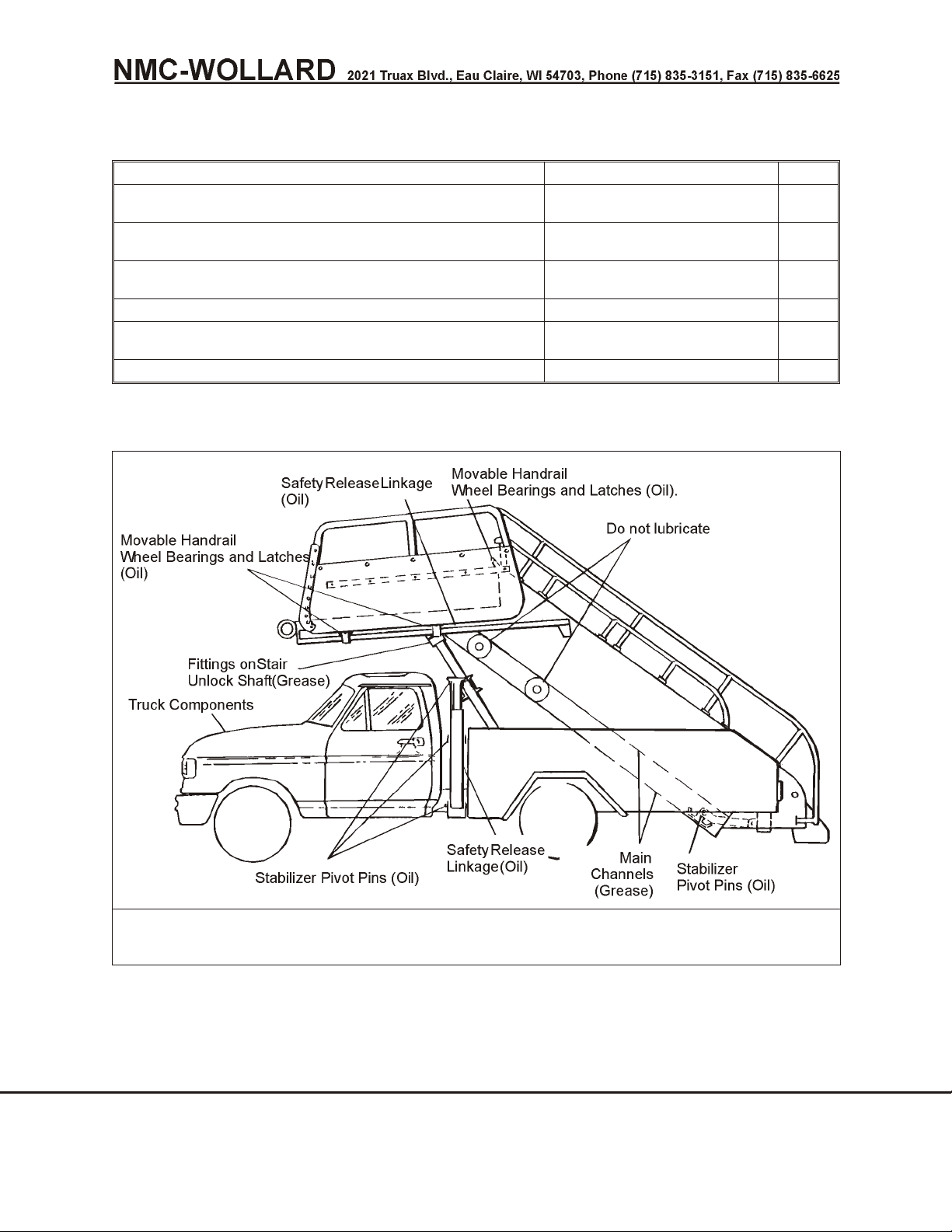
Truck Mounted Passenger Stair TMPS-200 Manual No. 307559
1.4 General Lubrication Diagram
Item Specification Fig.
Lubricate stair unlock mechanism shaft through
All purpose grease 1
the grease fittings on each shaft bracket.
Lubricate the safety release linkage to both the
SAE No.10 1
stair and upper frame support.
Lubricate the moveable handrail wheel bearings
SAE No. 10 1
and latches.
Apply coating of grease to inside of main channel. All purpose grease 1
Lubricate truck components as recommended by
Ford F300 manual 1
truck manufacturer.
Lubricate stabilizer pivot pins. SAE No. 10 1
FIGURE 1.
LUBRICATION POINTS
CHAPTER 2 MAINTENANCE SEPTEMBER 30, 2008
1 SERVICING PAGE 5
Page 68

Truck Mounted Passenger Stair TMPS-200 Manual No. 307559
This Page Intentionally Blank
SEPTEMBER 30, 2008 CHAPTER 2 MAINTENANCE
PAGE 6 1 SERVICING
Page 69
Truck Mounted Passenger Stair TMPS-200 Manual No. 307559
2 TROUBLE SHOOTING
Perform lock out/tagout pro ce dures be fore ad just ing, lu bri cat ing,
clean ing or oth er wise ser vic ing. Fail ure to do so could re sult in un ex pected startup and
could cause se ri ous in jury or death.
2.1 Basic Troubleshooting - Hydraulic System
Problem Possible Cause Remedy
Adjustable
section,
stabilizers, or
A-frame won't
operate
Insufficient hydraulic oil in
system
Add oil in reservoir to "FULL"
mark on dipstick. Avoid
overfilling by checking and
replenishing oil supply only
when all hydraulic cylinders
are fully retracted.
Shutoff valve in suction line
under truck not open
Belt worn, slipping, or broken
Leaks in hydraulic system
Dirty Y-strainer
Hydraulic pump defective
Hydraulic cylinder defective
System pressure relief valve
defective or improperly
adjusted
Stair or A-frame unlock
solenoid defective
Electrical Controls Not
Functioning
Solenoid Valve Or Unloader
Valve Not Functioning
Magnetic Pump Clutch not
energizing when Master
Switch is on.
Open valve.
Replace belt if worn or tension
is out of spec.
Check all lines, connections
and components for leaks.
Tighten or replace leaking
components.
Clean strainer with a grease
solvent.
Repair or replace pump.
Repair or replace cylinder.
Replace relief valve section of
control valve.
Check for voltage to solenoid
and control relay.
Check continuity.
Replace solenoid.
Adjust linkage.
See Schematics, Figures 3 &
4.
See Figure 7.
See Hydra force Combination
Valve - 307575 in Chap.5.
See Schematics, Figures 3 &
4.
CHAPTER 2 MAINTENANCE SEPTEMBER 30, 2008
2 TROUBLE SHOOTING PAGE 1
Page 70

Truck Mounted Passenger Stair TMPS-200 Manual No. 307559
2.2 Basic Troubleshooting - Mechanical
Problem Possible Cause Remedy
Front only or rear
Supply hose leaking
Check hose for pressure.
only stabilizers
operate.
Upper section of
A-frame will not
Pilot-operated check valve
defective
A-frame flow control valve
defective
Replace defective
pilot-operated check valve.
Replace valve.
raise
A-frame will not
lower
Breather plug in cylinder
obstructed
Front support frame unlock
solenoid defective
Remove and clean breather
plug.
Refer to Hydraulic System
troubleshooting.
Adjustable section
will not extend;
stabilizers will
extend
Adjustable section
will not lower
Adjustable section
lowers too slowly
Unlock pawl loose on shaft
Flow control valve defective
Adjustable section overloaded
Foreign matter between
channels and main support
wheels
Objects left on stair treads
jammed between intermediate
platform and adjustable
platform
Stair unlock solenoid defective
System relief valve set too low
Foreign matter between
channels and main support
wheels
Check pawls for security;
replace roll pins if missing or
defective.
Replace flow control valve.
Adjust load.
Clean channels and wheels.
Lubricate channels with
all-purpose grease.
Raise section and remove
objects; check for damage.
Refer to Electrical System
troubleshooting.
Adjust relief valve to 1,200
psi (84.37 kgps cm).
Clean channels and wheels.
Lubricate channels with
all-purpose grease.
SEPTEMBER 30, 2008 CHAPTER 2 MAINTENANCE
PAGE 2 2 TROUBLE SHOOTING
Page 71

Truck Mounted Passenger Stair TMPS-200 Manual No. 307559
2.3 Basic Troubleshooting - Electrical System
Problem Possible Cause Remedy
"STABILIZERS
NOT RETRACTED"
Proximity switch improperly
adjusted
Readjust switch.
indicator does not
go out when
Proximity switch defective
Replace defective switch.
stabilizer is
retracted
Pawls do not
disengage ratchet
teeth upon
command from
Relay CR4 defective
Defective unlock solenoid on
stair or A-frame locking
mechanism
Replace defective relay.
Refer to "Hydraulic
System/Adjustable Section
"...will not operate" at
beginning of this table.
SAFETY RELEASE
switch
No response from
Open circuit
Check wiring for continuity.
any electrical
command
Defective 70-amp main power
Replace circuit breaker.
supply circuit breaker
"Stabilizer Not
Retracted"
indicator lamp
does not light
when stabilizer is
extended
"LIGHTS ON"
indicator light or
platform spotlight
does not illuminate
when switch is on
Stair lights,
indicator light
and/or stair tread
illuminating lights
do not illuminate
when "LIGHTS"
switch is on
Defective main power relay
CR1
Defective indicator
Limit switch actuators stuck
Limit switches improperly
adjusted
Limit switches defective
Defective circuit breaker
Defective spotlight lamp and/or
spotlight indicator lamp
Defective switch
Defective 25-amp circuit
breaker
Short in wiring
Defective lamp
Defective switch
Defective 25-amp circuit
breaker
Open circuit
Check for voltage. Replace
relay.
Replace indicator.
Check switch actuators.
Replace switch if defective.
Readjust switches.
Replace switches.
Replace appropriate 20-amp
circuit breaker
Replace lamp.
Replace switch.
Replace circuit breaker.
Check wiring and repair.
Replace lamp.
Replace switch.
Replace circuit breaker.
Check continuity and repair.
Short in wiring
CHAPTER 2 MAINTENANCE SEPTEMBER 30, 2008
2 TROUBLE SHOOTING PAGE 3
Check wiring.
Page 72
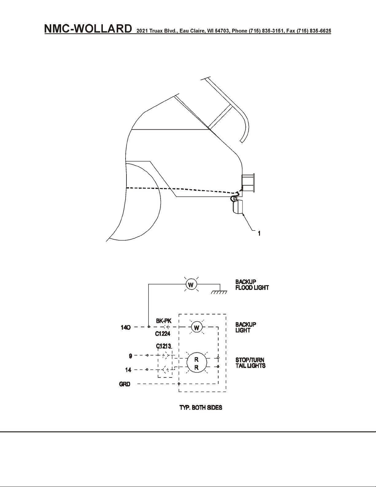
Truck Mounted Passenger Stair TMPS-200 Manual No. 307559
2.4 Electrical and Hydraulic Schematics and Diagrams
18359
FIGURE 1.
LIGHTS, FLOOD, BACKUP, OPTION
SEPTEMBER 30, 2008 CHAPTER 2 MAINTENANCE
PAGE 4 2 TROUBLE SHOOTING
Page 73
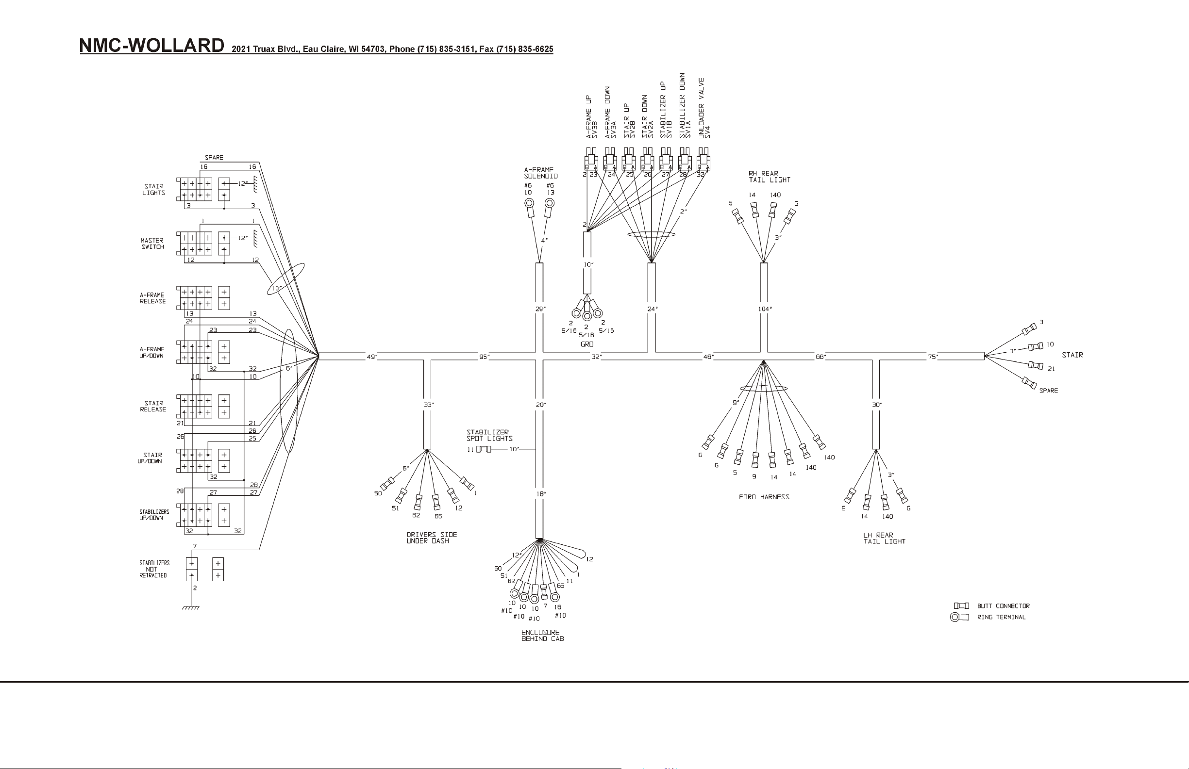
Truck Mounted Passenger Stair TMPS-200 Manual No. 307559
SEE CHAP. 5, HYDRA FORCE COMBINATION VALVE
307609
FIGURE 2.
HARNESS, CHASSIS
CHAPTER 2 MAINTENANCE SEPTEMBER 30, 2008
2 TROUBLE SHOOTING PAGE 5
Page 74
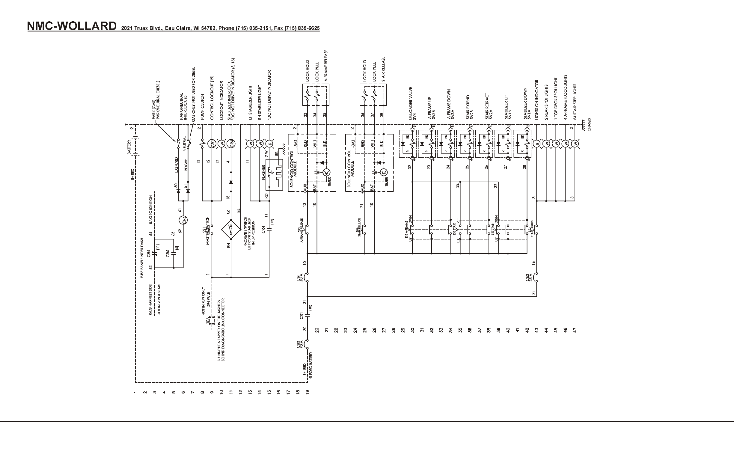
Truck Mounted Passenger Stair TMPS-200 Manual No. 307559
307556-1
FIGURE 3.
ELECTRICAL SCHEMATIC, GAS/DSL, MANIFOLD HYD’S
SEPTEMBER 30, 2008 CHAPTER 2 MAINTENANCE
PAGE 6 2 TROUBLE SHOOTING
Page 75
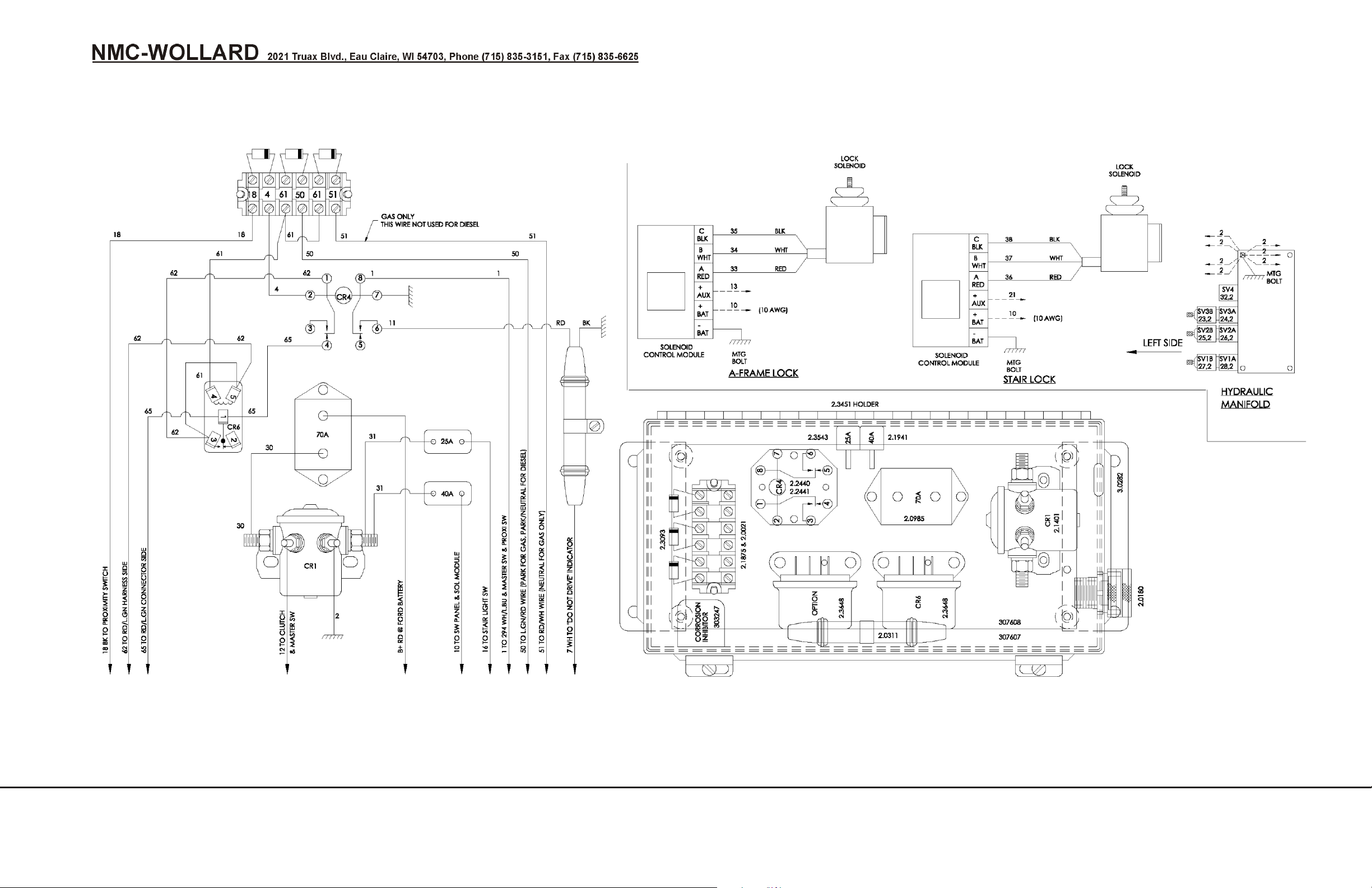
Truck Mounted Passenger Stair TMPS-200 Manual No. 307559
307556-2
307556-3
FIGURE 4.
WIRING DIAGRAM, GAS/DSL, MANIFOLD HYD’S
CHAPTER 2 MAINTENANCE SEPTEMBER 30, 2008
2 TROUBLE SHOOTING PAGE 7
Page 76
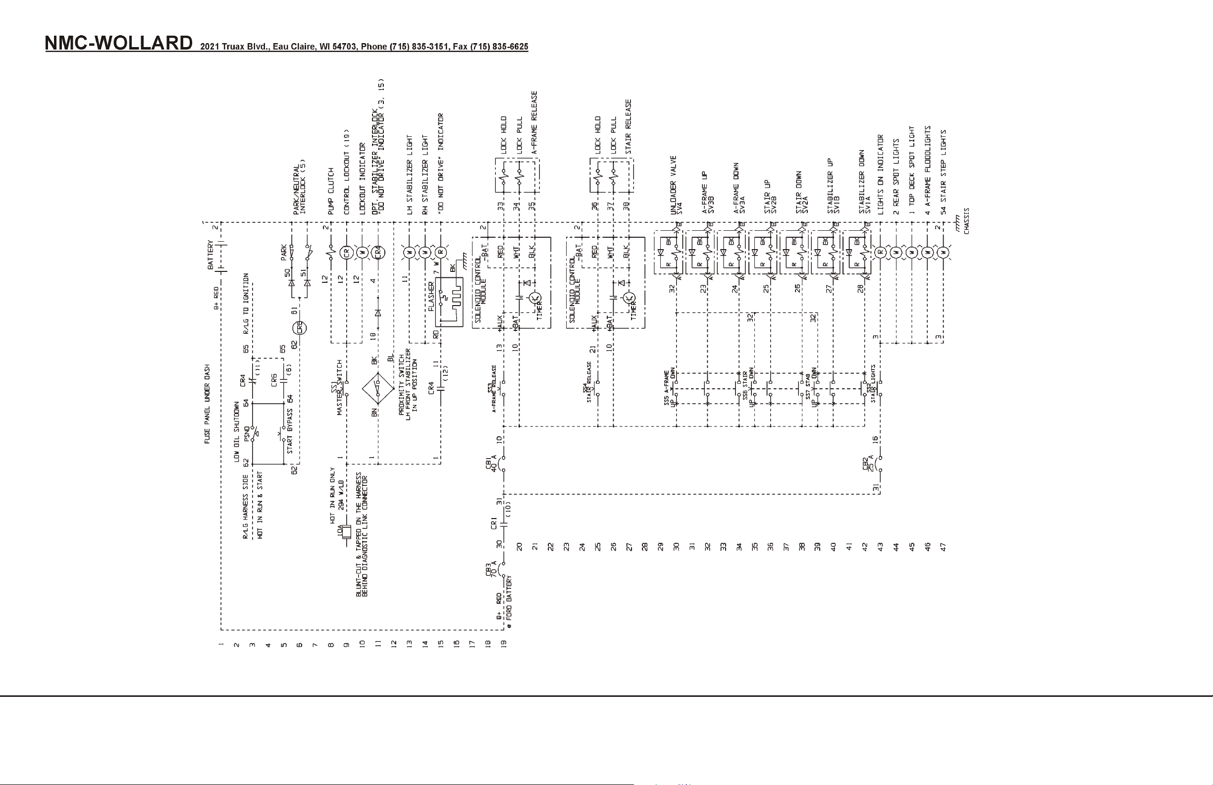
Truck Mounted Passenger Stair TMPS-200 Manual No. 307559
307619
FIGURE 5.
SHUT DOWN, LOW OIL, TMPS200, GAS/DSL, OPTION, ELEC. SCHEMATIC (SN 1381+)
SEPTEMBER 30, 2008 CHAPTER 2 MAINTENANCE
PAGE 8 2 TROUBLE SHOOTING
Page 77
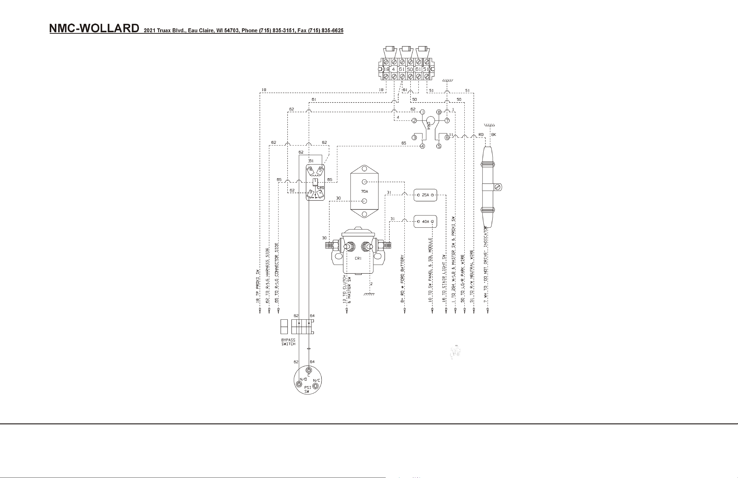
Truck Mounted Passenger Stair TMPS-200 Manual No. 307559
307619
FIGURE 6.
SHUT DOWN, LOW OIL, TMPS200, GAS/DSL, OPTION, WIRING DIAGRAM
CHAPTER 2 MAINTENANCE SEPTEMBER 30, 2008
2 TROUBLE SHOOTING PAGE 9
Page 78
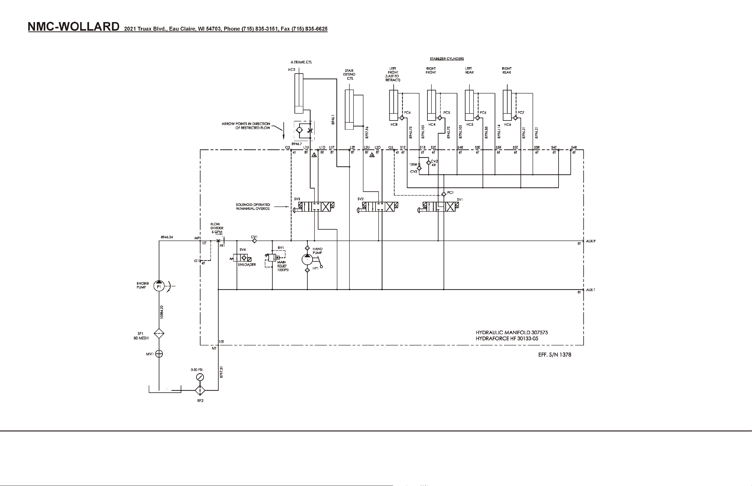
Truck Mounted Passenger Stair TMPS-200 Manual No. 307559
307612
FIGURE 7.
HYDRAULIC SCHEMATIC
SEPTEMBER 30, 2008 CHAPTER 2 MAINTENANCE
PAGE 10 2 TROUBLE SHOOTING
Page 79
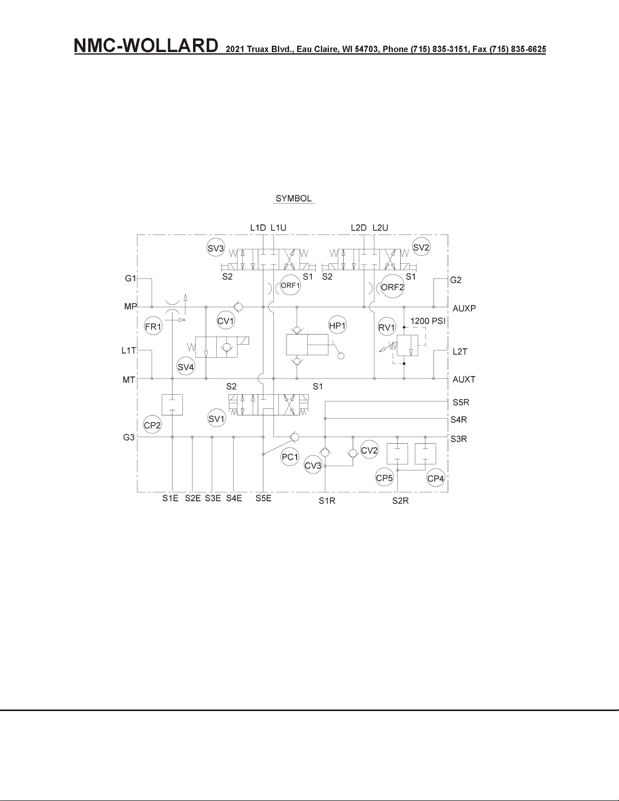
Truck Mounted Passenger Stair TMPS-200 Manual No. 307559
307575
FIGURE 8.
HYDRAULIC MANIFOLD, LIFT/STABILIZER
CHAPTER 2 MAINTENANCE SEPTEMBER 30, 2008
2 TROUBLE SHOOTING PAGE 11
Page 80

Truck Mounted Passenger Stair TMPS-200 Manual No. 307559
This Page Intentionally Blank.
SEPTEMBER 30, 2008 CHAPTER 2 MAINTENANCE
PAGE 12 2 TROUBLE SHOOTING
Page 81
Truck Mounted Passenger Stair TMPS-200 Manual No. 307559
3 REMOVAL AND INSTALLATION
Perform lock out/tagout pro ce dures be fore ad just ing, lu bri cat ing,
clean ing or oth er wise ser vic ing. Fail ure to do so could re sult in un ex pected startup and
could cause se ri ous in jury or death.
Using non-original replacement parts is not recommended. Their use
may cause unit failure and/or affect vehicle safety.
NOTE: The instructions in this chapter are recommended procedures only.
Procedures may be altered to fit the user's needs and facilities.
3.1 Stair Assembly
3.1.1 Special Tools and Equipment
The following equipment is needed to perform this operation:
• 2 hoists.
• 2 cable slings.
• 1 forklift (or a combination of 1 hoist and 1 forklift or other suitable means
of lifting the stair components).
• 3 open-top tables approximately 3 feet high, 4 feet wide and 5 feet long,
mounted on casters (required to handle the main and adjustable stair
sections).
• 2 lift pins (Part # LP36D2-038-1) or 3/4 X 4" hex head bolts and nuts.
• 1 length of 1-1/4" pipe, 8 feet long.
• 1-1/8" pipe nipple.
• 6 feet of 1/8-inch rubber hose (neoprene or other oil resistant type).
3.1.2 Stair Removal
1. Support upper end of stair by placing a pipe (1-1/4-inch standard pipe or
other member of sufficient length and strength), across the underside of
the top platform so that it protrudes out each side.
2. Suspend two cable slings from a hoist and place a sling around each pipe
end so it cannot slip off or shift.
3. Remove the bolts from each side of the lower end of the main section at
lower handrail attach angles and insert lift pins. (3/4-inch hex head bolts
and nuts can be substituted if Wollard lift pins are not available.)
4. Using a second hoist with cable slings, attach slings to pins (or bolts).
CHAPTER 2 MAINTENANCE SEPTEMBER 30, 2008
3 REMOVAL AND INSTALLATION PAGE 1
Page 82

Truck Mounted Passenger Stair TMPS-200 Manual No. 307559
5. Turn hydraulic shutoff valve (located between tank and Y-strainer) to
"OFF" position before disconnecting hydraulic lines.
6. Disconnect battery.
7. Disconnect all electric wires and hydraulic lines from truck section to the
stair. Cap all open hydraulic lines and ports.
8. Take sufficient strain on forward hoist and disconnect A-frame from main
stair section by removing two attaching bolts.
9. Remove the two attach bolts from lower end of main stair frame.
10. Be sure all lines and cables are disconnected and clear. Hoist stair
assembly from support frame and drive truck away.
3.1.3 Stair Installation
1. Set adjustable section to lowest position on the main section.
2. Replace bolt in each lower handrail attach angle with lift pins. (3/4-inch
hex head bolts and nuts can be substituted if Wollard lift pins are not
available.) Attach hoist cables to lift pins.
3. Support upper end of stair by placing a 1-1/4-inch pipe of sufficient length
across underside of top platform so that it protrudes out each side. Place
hoist cable sling around each pipe end making sure that it cannot slip off
or damage platform.
4. Hoist stair assembly to sufficient height.
5. Back truck section under stair assembly.
6. Align attach lugs of main section with attach lugs at lower end of main
stair frame.
7. With upper end of stair assembly at sufficient height, align A-frame lugs
with upper lugs on main stair. Install bolts.
8. Slowly release strain from hoist at upper end of stair and remove pipe
support and slings.
9. Connect all electric wires and hydraulic lines from truck section to stair
assembly.
10. Release strain from hoist at lower end of stair and remove sling and lift
pins.
11. Replace original bolts through lower handrail attach angles.
12. Start engine.
13. Hold stair "SAFETY RELEASE" switch on and slowly operate "STAIR
UP/DOWN" control handle to extend and retract cylinder to allow air to
exit system. Lower stair and release "SAFETY RELEASE" switch.
14. Stop engine.
15. Check for hydraulic oil leaks.
SEPTEMBER 30, 2008 CHAPTER 2 MAINTENANCE
PAGE 2 3 REMOVAL AND INSTALLATION
Page 83

Truck Mounted Passenger Stair TMPS-200 Manual No. 307559
3.2 Separating and Mating Stair Sections
3.2.1 Separating Stair Sections
1. Remove stairs from truck as outlined in preceding paragraphs.
2. Using a hoist, raise lower end of main section to approximately four feet
above floor level.
3. Roll an open-end work table under stair and position with one end as
close as possible to the underside of the top platform.
4. Lower platform end of stair onto table so that notches in safety rack will
rest solidly when stair is fully lowered.
5. Lower the lower end of stair onto the table. Remove the hoist cable and
pipe from top platform.
6. Place a table at lower end of main section.
7. Roll tables apart to extend adjustable section about ten inches. Remove
clevis pin from upper end of hydraulic cylinder.
8. Disconnect tread light cable at splice on underside of adjustable section.
9. Roll table holding the adjustable section away from main section while
simultaneously rolling a second table under main section.
IMPORTANT! To prevent main section from dropping onto table when
adjustable section is pulled clear, main section should be blocked up just
before adjustable section channels pass centerline of upper wheels.
3.2.2 Mating Stair Sections
NOTICE! Before mating adjustable section to main section, make sure that the
channel tracks are clean and free of any foreign matter.
1. Apply a thin coat of all-purpose grease (Valvoline X-ALL MP grease or
equivalent) approximately two inches wide down center of inside of each
channel for entire length. Make sure that steel wheels on main section
turn freely and are clean and lubricated.
2. If not already done, install lift pins in handrail lower attach angle on main
section and slip on rig hoisting sling.
3. Make sure that upper end of main section has sufficient clearance from
work table to allow mating of adjustable section.
4. Roll table with adjustable section into position with main section and slip
the adjustable section channels over upper wheels on main section. Take
care that wiring is kept clear while mating sections.
CHAPTER 2 MAINTENANCE SEPTEMBER 30, 2008
3 REMOVAL AND INSTALLATION PAGE 3
Page 84

Truck Mounted Passenger Stair TMPS-200 Manual No. 307559
5. When adjustable section has mated sufficiently with main section,
remove blocks from under upper end of main section and continue
slipping sections together until upper platform level is approximately ten
inches from highest step position on main platform.
6. Connect tread light cable at splice on underside of adjustable section.
7. Align holes in piston of hydraulic cylinder with holes in lugs of attaching
brackets and insert clevis pins and lock pins. Slide sections together until
upper platform level aligns with highest step of main section.
3.3 Stair Cylinder Removal and Replacement
3.3.1 Stair Cylinder Removal
NOTE: It is not necessary to remove the stair assembly to remove the cylinder.
1. Remove fiberglass side panels to allow clearance for lifting procedure in
step 7.
2. Remove bolts from each side of lower end of main section at handrail
attachment angles. Insert lift pins.
3. Raise hoist to lift weight of stairs from cylinder lower attach point.
4. Relieve hydraulic pressure from cylinder by operating cylinder control
lever.
5. Disconnect hydraulic lines from cylinder.
6. Remove two 3/4-inch bolts and tie-downs attaching stairs to lower end of
main stair frame.
7. Lift rear of stairs 3 to 4 feet. Upper portion will pivot at two attach points.
8. Remove lock pin from clevis pin in lower clevis of cylinder. Support end of
cylinder and remove clevis pin.
9. Remove four bolts and nuts securing cylinder bracket and remove
bracket.
10. Pull upper stair portion slightly forward if necessary to expose upper
cylinder attach point.
11. Remove lock pin and clevis pin from upper clevis.
12. Pull cylinder out through hole exposed by removal of lower cylinder
bracket.
13. Install the cylinder using the reverse removal instructions.
14. Start engine.
15. Hold stair "SAFETY RELEASE" switch on and slowly operate "STAIR
UP/DOWN" control handle to extend and retract cylinder to allow air to
exit system. Lower stair and release "SAFETY RELEASE" switch.
16. Stop engine.
SEPTEMBER 30, 2008 CHAPTER 2 MAINTENANCE
PAGE 4 3 REMOVAL AND INSTALLATION
Page 85

Truck Mounted Passenger Stair TMPS-200 Manual No. 307559
17. Check for hydraulic oil leaks.
18. Replace side panels.
3.4 A-Frame Removal and Installation
3.4.1 A-Frame Removal
1. Remove side panels.
2. Support upper end of stair by placing a pipe (1-1/4" standard pipe is
excellent), or other member of sufficient size and strength, across
underside of top platform so that it protrudes from each side.
3. Suspend two cable slings from a hoist and place one sling around each
pipe end. Assure that slings cannot slip off or shift.
4. Turn hydraulic shutoff valves under truck to "OFF" position. Disconnect
hydraulic lines to A-frame lift cylinder. Plug open lines and ports.
5. Disconnect electrical leads to A-frame unlock relay solenoid and
spotlight.
6. Raise hoist sufficiently to take load off the two upper attach bolts (main
stair to A-frame). Remove upper attach bolts and nuts.
7. Raise hoist enough to provide clearance for removal of A-frame.
8. Clear A-frame of all attached wiring and hydraulic lines.
9. Support upper end of A-frame. Remove the attach bolts and nuts
securing lower end of A-frame to stair support frame.
10. Using a second hoist, lift A-frame clear of attach lugs and remove from
either side of truck. Move to work area for further breakdown.
11. Keep upper end of stair supported by first hoist.
12. Disassemble lift portion of A-frame (reference Chapter 4).
13. Install in opposite of removal procedures.
14. When installation is complete, start engine and slowly extend and retract
cylinder to allow air to exit system.
15. Stop engine and check for hydraulic oil leaks.
3.5 Main Stair Frame Removal and Installation
3.5.1 Main Stair Frame Removal
1. Remove stair assembly.
2. Remove A-frame.
3. Remove bolts, nuts and straps holding main support frame.
4. Make sure all wires, lines, and hoses are clear. Attach suitable hoist
cable slings to frame and lift frame from truck.
CHAPTER 2 MAINTENANCE SEPTEMBER 30, 2008
3 REMOVAL AND INSTALLATION PAGE 5
Page 86
Truck Mounted Passenger Stair TMPS-200 Manual No. 307559
3.5.2 Main Stair Frame Installation
Installation is the reverse of removal.
3.6 Electrical Components Removal and Installation
Electrical system components are conventional items requiring conventional
methods of mounting. An automotive mechanic possessing normal skills can
accomplish removal and installation of any electrical part with little effort. Use
the schematic diagram in this Chapter and the exploded views and parts
listings in Chapter 4 as a guide.
3.7 Hydraulic System
Plumbing within the hydraulic system uses standard hydraulic lines, fittings,
and hoses. Relief and check valve installations follow normal hydraulic system
layout and mounting methods, assuring uncomplicated maintenance
procedures. Major assemblies require more attention to installation methods.
During removal of major components, observe mounting and installation, type
of mounting hardware, and note order of disassembly. Also note any other
peculiarities which will assist during installation. After replacing any component
in the hydraulic system, run a complete operational check.
NOTICE! Use only MOBIL DTE-13 or equivalent in operating temperatures of
+20°F to +120°F (-7°C to +50°C). Use Mobil Aero HFA or equivalent
(MIL-H-5606A) in operating temperatures of -25°F to +50°F (-32°C to +10°C).
Do not use hydraulic oils of different specifications. They may not be
compatible and could result in damage to the hydraulic system components.
3.7.1 Hydraulic System Safety
To minimize risk of serious injury or death, follow these
hydraulic servicing precautions:
Follow all necessary lockout/tagout procedures.
• Hydraulic systems have residual, stored pressure. Relieve all pressure
from the hydraulic system before servicing.
• Allow fluid to cool before working on system.
• Hydraulic fluid escaping under pressure can have sufficient force to enter
eyes and penetrate skin. If fluid gets in eyes or skin, flush with large
quantities of water and seek medical attention.
• Wear eye protection when servicing hydraulic components or systems.
• Keep all hoses and connections in good serviceable condition. Check
before start-up and periodically during operation.
• Do not investigate for leaks with hands. Use a large piece of cardboard.
SEPTEMBER 30, 2008 CHAPTER 2 MAINTENANCE
PAGE 6 3 REMOVAL AND INSTALLATION
Page 87

Truck Mounted Passenger Stair TMPS-200 Manual No. 307559
3.7.2 Hydraulic System Procedures
NOTICE! To minimize hydraulic system damage, do the following:
• Clean li ness is the best way to in sure sat is fac tory com po nent life, on ei ther
new or re paired units. Cleaning parts by us ing a sol vent wash and air
dry ing is ad e quate if clean sol vent is used. This is pre ci sion equip ment.
The in ter nal mech a nism and re lated items must be kept free of for eign
ma te ri als and chem i cals.
• Pro tect all ex posed seal ing sur faces and open cav i ties from dam age and
for eign ma te ri als.
• Al ways re place gas kets and O-rings. Clean gas ket seal ing sur faces prior to
in stall ing new gas ket. Lightly lu bri cate all O-rings with clean pe tro leum jelly
prior to as sem bly.
• Keep oil stor age ar eas clean and dry.
• Keep bar rel bungs cov ered and sealed un til you’re ready to use the oil.
Clean the bung seals be fore re mov ing them, and clean the bung be fore
re mov ing it.
• Use only clean pumps and con duits to trans fer fluid from bar rels to the
res er voir. Clean the sys tem’s en try port thor oughly.
• Fil ter all fluid in tro duced into the res er voir through a nom i nal, no-bypass,
10-micron fil ter. Do not use a bucket or such method.
• Never add used fluid to the sys tem. The high costs of down time and
com po nent re place ment is more costly than the price of new oil.
• Never mix hy drau lic flu ids. It is highly pos si ble that the ad di tive pack age of
one fluid will not be com pat i ble with the other’s ad di tives. You can end up
with a fluid in which none of the ad di tive pack ages do their jobs.
• In the event of a cat a strophic fail ure of a pump or mo tor: Drain, clean, flush
the sys tem, and change fil ters. Oth er wise, metal par ti cles and dirt can
re main in the sys tem to cause dam age af ter you re place the com po nent.
3.8 Wheel Mounting (Dual Rear Wheels)
Dual rear wheel vehicles are equipped with wheels attached to the wheel hubs
with integral two-piece swiveling lug nuts. Lug nut torque must be 140 ft-lbs. +
15 ft-lbs.
Wheel change includes both front and rear wheels on dual rear wheel vehicles.
CHAPTER 2 MAINTENANCE SEPTEMBER 30, 2008
3 REMOVAL AND INSTALLATION PAGE 7
Page 88
Truck Mounted Passenger Stair TMPS-200 Manual No. 307559
To minimize the risk of tire/wheel failure and loss of vehicle
control, when servicing tire/wheels:
• Do not use cleaning solvent on tires. Solvents cause deterioration of the
rubber.
• Never inflate tires with air from systems using alcohol evaporators.
• Never mix rim parts of different manufacturers or different sizes.
• Do not use damaged parts.
After initially mounting wheel and tire assembly, recheck lug
nut torque after the first hour of operation and after the first 8 hours of
operation. After this, check monthly or every 250 hours, whichever comes first.
Do not lube wheel studs as it will result in inaccurate tightening torque. Failure
to follow these procedures could result in wheel mounting failure and loss of
vehicle control.
3.9 Installation and Removal of Optional Extended Stair
3.9.1 Extended Stair Instructions
The extended stair option has three main parts: the Step Platform Assembly,
the Deck Bumper Assembly, and the Wing Handrail Assembly.
The step platform assembly consists of a platform that provides an extra 16
inches of height above the standard deck and an extra 16 inches further
forward of the standard deck. It is shipped fully assembled and installed to the
top stair deck.
The deck bumper is included for use on the standard level deck only if the
platform is removed.
The wing handrails and wings are shipped uninstalled. To install:
1. Unpack both wings and lay each on a non-scratch surface, flat side
down.
2. Lay the right-hand wing handrail over the right-hand wing so the bracket
holes line up with the holes in the wing frame.
3. Attach the handrail to the inside of the wing using 1/4-20 x 2.25
capscrews installed from either the top or the inside.
4. Do the same with the left-hand wing.
5. Install wings as described in Chapter 2 of the Wollard 252 manual.
SEPTEMBER 30, 2008 CHAPTER 2 MAINTENANCE
PAGE 8 3 REMOVAL AND INSTALLATION
Page 89

Truck Mounted Passenger Stair TMPS-200 Manual No. 307559
3.9.2 Removing the Step Platform Assembly
If you want to remove the step platform assembly in order to reach lower
aircraft door sill heights, perform the following steps:
1. Place stair and A-frame in DOWN position.
2. Remove the right-hand and left-hand wings.
3. Remove the sixteen ½-inch capscrews that hold the step platform to the
main deck.
4. Using appropriate slings and forklift (or crane), lift the step platform off of
the main deck and place on ground away from the work area.
5. Remove the wing handrails from the wings.
6. Reinstall the wings. Refer to Chapter 2.
NOTICE! If you remove the step platform, you must install the deck bumper
onto the main deck. The bumper provides structural support to the deck as well
as protecting aircraft from damage.
7. Install the deck bumper assembly to the front of the deck. Place washers
and locknuts on the four studs after they are installed through the deck
frame.
3.9.3 Reinstalling the Step Platform Assembly
Follow the above procedures in reverse order.
NOTICE! The deck bumper must be removed if the step platform is installed. If
left on, the deck bumper will block the stair operator's view of the platform
bumper, possibly resulting in damage to aircraft.
CHAPTER 2 MAINTENANCE SEPTEMBER 30, 2008
3 REMOVAL AND INSTALLATION PAGE 9
Page 90
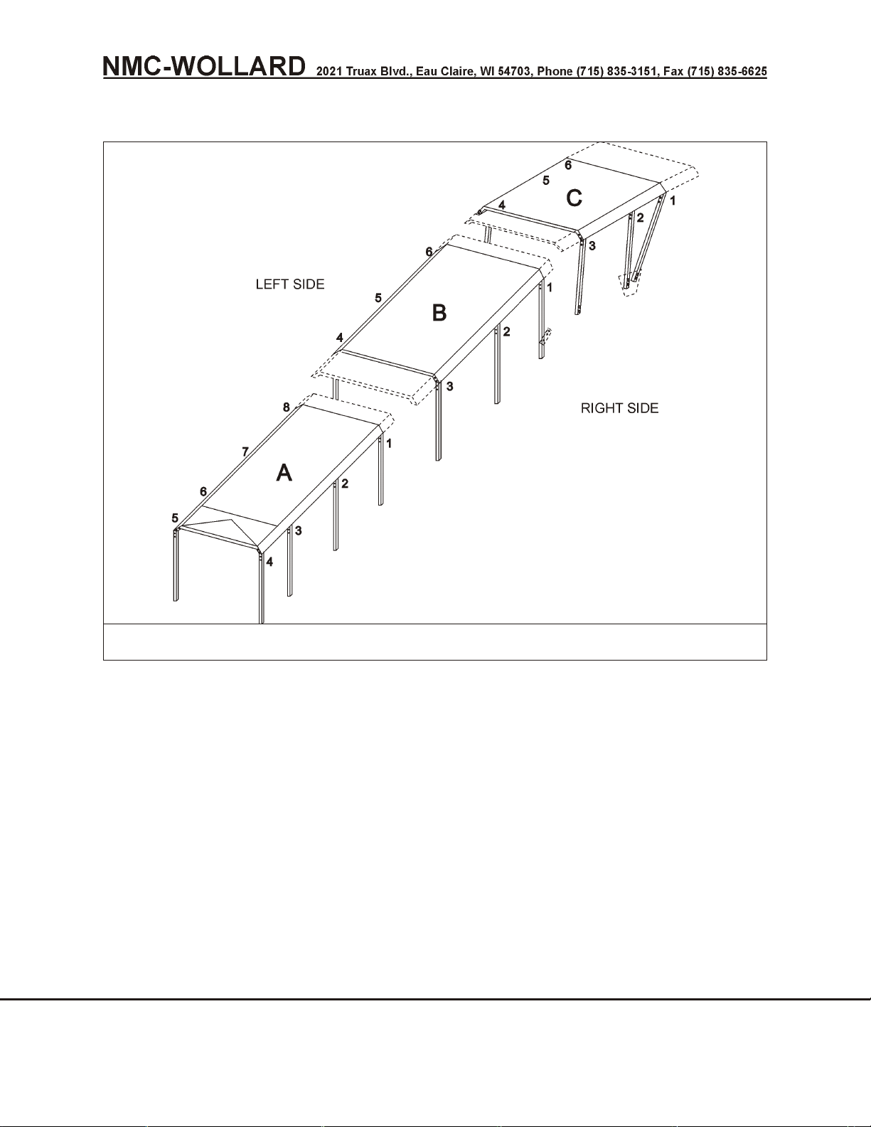
Truck Mounted Passenger Stair TMPS-200 Manual No. 307559
3.10 Installation of Optional Canopy
FIGURE 1. OPTIONAL CANOPY
3.10.1 Deck Section
Figure 2
The Deck section is the first canopy section to be installed. The stair must be
DOWN.
1. Unpack wings and all canopy components.
2. Install wings onto stair deck. See instructions in the Passenger Stair
Manual.
3. Install a temporary safety guard between the deck forward handrails.
Suggested method: A steel bar or heavy wood beam secured to handrails
with 10-15 wraps of reinforced tape (such as duct tape).
SEPTEMBER 30, 2008 CHAPTER 2 MAINTENANCE
PAGE 10 3 REMOVAL AND INSTALLATION
Page 91
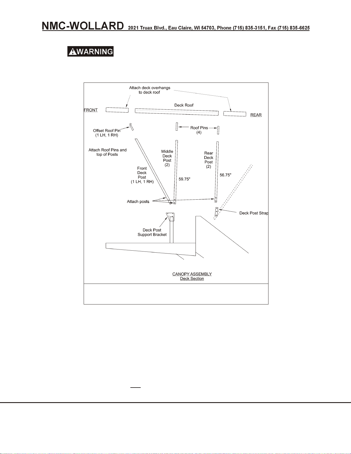
Truck Mounted Passenger Stair TMPS-200 Manual No. 307559
Install a temporary safety guard between handrails across
front of deck to help prevent a fall and furthermore each person working on the
stair deck should wear a safety harness secured to the deck.
FIGURE 2.
CANOPY ASSEMBLY DECK SECTION
Place deck section canopy on a non-scratch surface, top side down.
4.
NOTE: Roof pins are shipped installed.
5. Install (6) deck posts onto the roof pins. Refer to Figure 2 to determine
correct location for the different post lengths. Secure the posts with 3/8
capscrews and washers. Capscrews must face the same direction.
6. Stand deck canopy section on its posts. Attach slings and lift deck section
using a crane, OR, with four people, lift the deck section and carry it up to
the stair deck.
CHAPTER 2 MAINTENANCE SEPTEMBER 30, 2008
3 REMOVAL AND INSTALLATION PAGE 11
Page 92
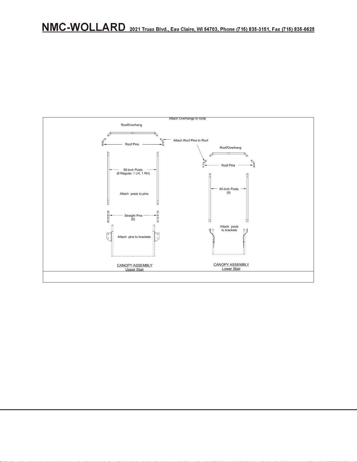
Truck Mounted Passenger Stair TMPS-200 Manual No. 307559
7. Secure front and middle posts to outside of mounting plate with 3/8
capscrews and washers. Capscrews should face inward.
8. Lower Section
3.10.2Lower Section
Figure 3 and Figure 4
FIGURE 3. CANOPY ASSEMBLY LOWER SECTION
1. Install the deck section can opy.
2. Place lower canopy section on a non-scratch surface, top side down.
NOTE: Roof pins are shipped installed.
3. Install (8) 40-inch posts onto the roof pins. Install, but do not tighten, 3/8 x
0.75 capscrews and washers. All capscrews should face out.
4. Raise the stair to its fullest extent.
5. Stand lower section on its posts. With one person on each post (6 people
needed), lift the section and carry it up the stair.
6. Place posts onto the brackets. Secure posts to brackets using 3/8 x 0.75
capscrews and washers. All capscrews should face out.
SEPTEMBER 30, 2008 CHAPTER 2 MAINTENANCE
PAGE 12 3 REMOVAL AND INSTALLATION
Page 93
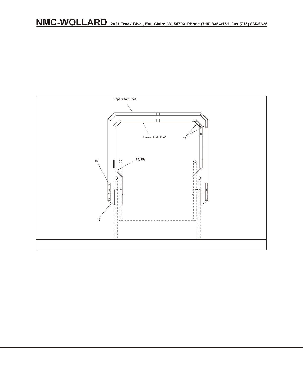
Truck Mounted Passenger Stair TMPS-200 Manual No. 307559
NOTE: The brackets are shipped installed on the stair.
7. Attach upper section overhang to upper section using 3/8 x 0.75
capscrews and washers.
8. Make sure upper Section handrails do not contact lower Section posts. If
needed, loosen handrail and/or post fasteners and move handrails and/or
posts and retighten fasteners.
FIGURE 4. CANOPY ASSEMBLY LOWER SECTION
3.10.3 Final Assembly
1. Stand directly behind the stairs and check that the each canopy Section
is centered and square. Check all clearances. Readjust as required.
2. Tighten 3/8-16 capscrews to pins inside aluminum tubes to 30 ft/lbs
torque.
3. Tighten capscrews through aluminum tubes without deforming washers
or tubes.
3.10.4Upper Section
Figure 5
CHAPTER 2 MAINTENANCE SEPTEMBER 30, 2008
3 REMOVAL AND INSTALLATION PAGE 13
Page 94

Truck Mounted Passenger Stair TMPS-200 Manual No. 307559
1. Install deck canopy Section and lower canopy Section.
2. Place upper canopy Section on a non-scratch surface, top side down.
NOTE: Roof pins are shipped installed.
3. Install (6) 59-inch posts onto the roof pins. Install, but do not tighten, 3/8 x
0.75 capscrews and washers. All capscrews should face the same
direction.
NOTE: Two posts have an extra hole 11 inches from the bottom. These belong
on the front pins. See Figure 5 to locate front end of canopy Section.
4. Raise stairs to maximum height.
5. Stand upper canopy Section on its posts. With one person on each post
(6 people needed), lift the Section and carry it over the lower Section and
up the stair.
6. Place posts onto the straight pins. Secure posts to straight pins using 3/8
x 0.75 capscrews and washers. At each joint, all four capscrews should
face the same direction.
7. Attach rear deck Section posts to front post brackets. Use a deck post
strap and three 3/8 x 2.75 capscrews, nuts, and washers on each post.
Locate strap and nuts on outside of tubes.
SEPTEMBER 30, 2008 CHAPTER 2 MAINTENANCE
PAGE 14 3 REMOVAL AND INSTALLATION
Page 95
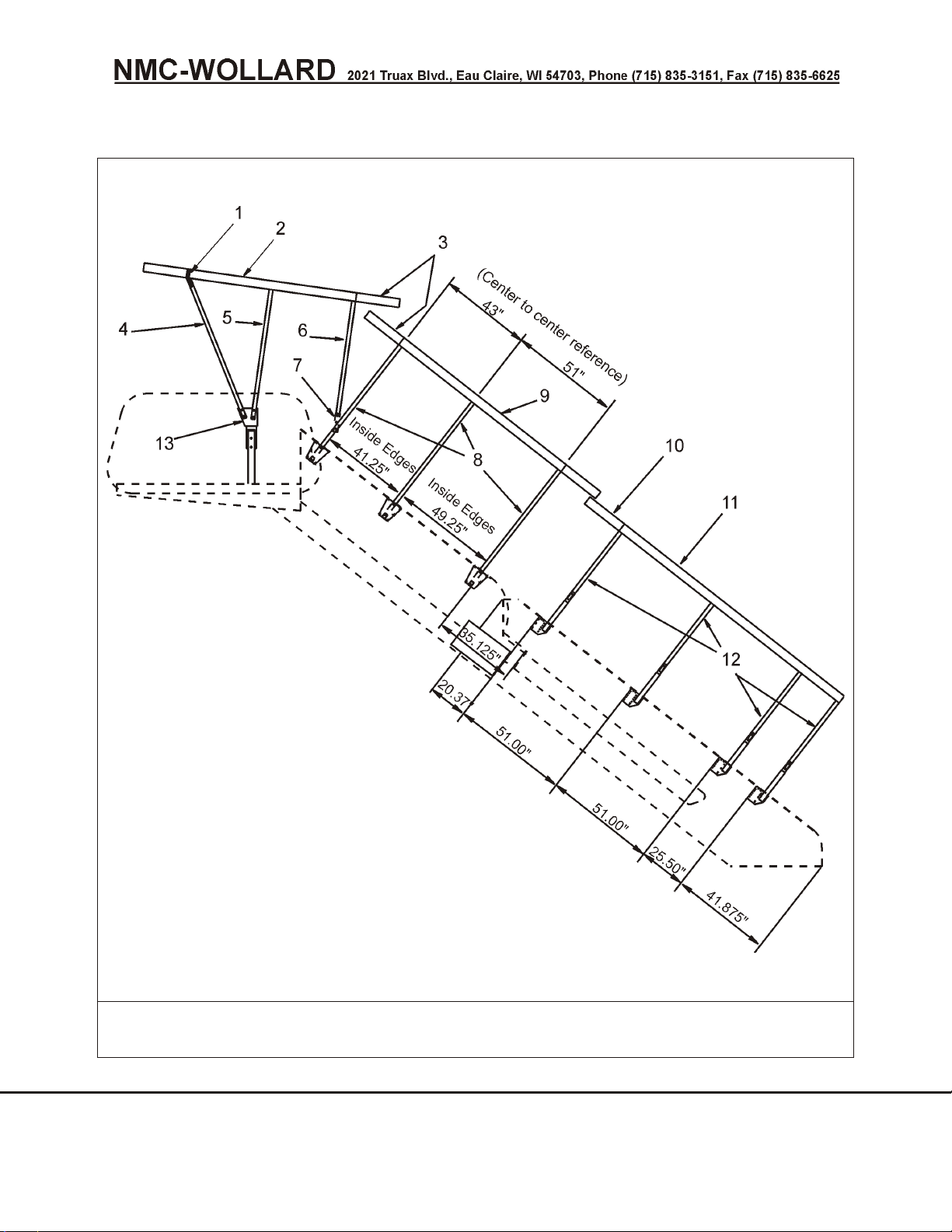
Truck Mounted Passenger Stair TMPS-200 Manual No. 307559
FIGURE 5.
UPPER STAIR SECTION
CHAPTER 2 MAINTENANCE SEPTEMBER 30, 2008
3 REMOVAL AND INSTALLATION PAGE 15
Page 96
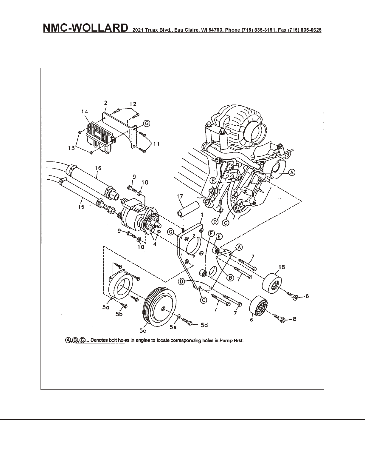
Truck Mounted Passenger Stair TMPS-200 Manual No. 307559
3.11 Ford 6.0L Diesel Clutch Pump Kit Installation
FIGURE 6. FORD 6.0L DIESEL CLUTCH PUMP KIT
1. Disconnect the battery.
2. Remove the air deflector shield from the top of the fan shroud.
SEPTEMBER 30, 2008 CHAPTER 2 MAINTENANCE
PAGE 16 3 REMOVAL AND INSTALLATION
Page 97

Truck Mounted Passenger Stair TMPS-200 Manual No. 307559
3. Remove the OEM intercooler tube.
4. Unbolt the electrical module (14) from its mounting bracket on the
passenger side valve cover. Keep it plugged in and just move it out of
the way for now. Unbolt the mounting bracket. It will not be needed
again. See figure 6.
5. Remove the OEM belt. The tensioner has a spring to lock it open without
any tension. Remove two bolts mounting the tensioner. Just let it lay
against the shroud to allow room to mount the pump bracket.
6. Loosen the battery hold down clamps and slide the battery out toward the
fender. Tighten the hold down clamps. Tie the air conditioner line to the
positive battery cable running down the rear of the battery. See figure 7.
7. Slip the small hose insulation sheath (15) over the pressure hose. Slip
the large hose insulation sheath (16) over the suction hose. Place the
sheaths where the hoses run close to the exhaust to protect the hoses
from the heat. Route the hoses back to the firewall and down running
them outside the frame.
8. Mount pump (4) onto bracket (1) with the two 3/8 x 1 1/4 bolts (9) with
two 3/8 flat washers (10). Install the adapter into the inlet and outlet ports
in back of the pump. Connect the hoses to the pump. Mount the bracket
onto the engine with the four M10 x 45 bolts (7). Reattach OEM
tensioner with the OEM bolts.
9. Mount the DewEze electrical module bracket (2) onto the front of the
pump bracket at location G with the two 1/4 x 3/4 bolts (11). Attach the
electrical module (14) to its bracket with two 1/4 x 1 bolts (12) and two 1/4
nuts.(13)
10. Mount the 3” diameter slotted-face idler pulley (6) to the boss on the
pump bracket at location F with an M10 x 40 Torx head shoulder bolt (8).
Mount the 2.50” diameter smooth-faced idler (18) to the boss at location
E with an M10 x 40 Torx head shoulder bolt.(8)
11. Mount the clutch coil (5a) to the pump bracket with four 1/4 x ½ flange
bolts (5b). Mount the clutch pulley (5c) to the pump shaft with the 5/16 x
1 1/4 bolt (5d) and heavy flat washer (5e) making sure the key is in place
on the shaft.
12. Install the belt as (19) shown in the diagram (Fig. 7). Release the lock on
the tensioner to tighten the belt.
13. Slit the 4” long hose (17) lengthwise in one wall if it is not already slit.
Slip the hose over the top of the pump bracket. Install the DewEze
intercooler tube (3) into the same location as the OEM tube was. It may
be necessary to loosen the hose clamp on the rubber elbow on the turbo
(location H) so the elbow can be rotated to line up with the intercooler
tube. Secure the tube with the OEM hose clamps.
CHAPTER 2 MAINTENANCE SEPTEMBER 30, 2008
3 REMOVAL AND INSTALLATION PAGE 17
Page 98

Truck Mounted Passenger Stair TMPS-200 Manual No. 307559
14. Hold the deflector shield in place on top of the fan shroud before
snapping into place, noting where it contacts the intercooler tube or the
clutch pulley. Trim away that portion of the shield. Snap the shield into
place making sure it does not make contact. See figure 7.
15. Reconnect the battery.
16. Run the engine and check for any clearance or alignment problems.
Adjust as needed.
SEPTEMBER 30, 2008 CHAPTER 2 MAINTENANCE
PAGE 18 3 REMOVAL AND INSTALLATION
Page 99
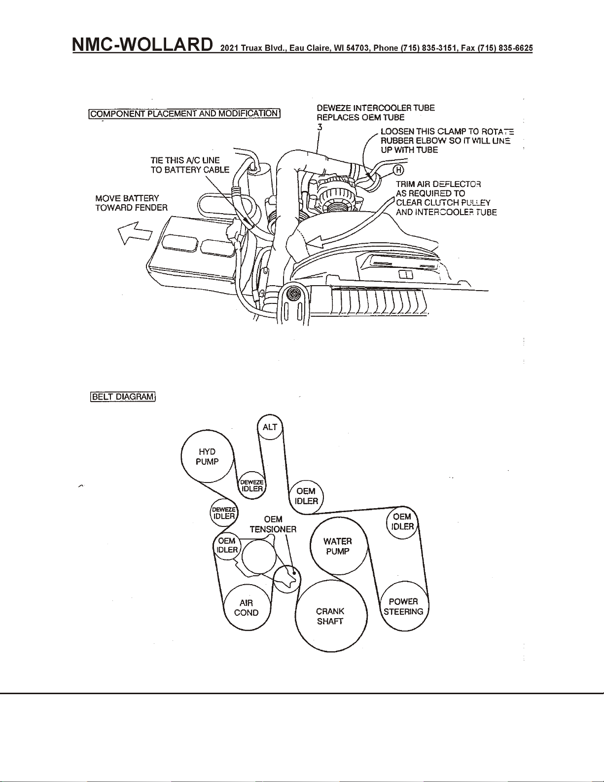
Truck Mounted Passenger Stair TMPS-200 Manual No. 307559
FIGURE 7. FORD 6.0L DIESEL CLUTCH PUMP KIT
CHAPTER 2 MAINTENANCE SEPTEMBER 30, 2008
3 REMOVAL AND INSTALLATION PAGE 19
Page 100
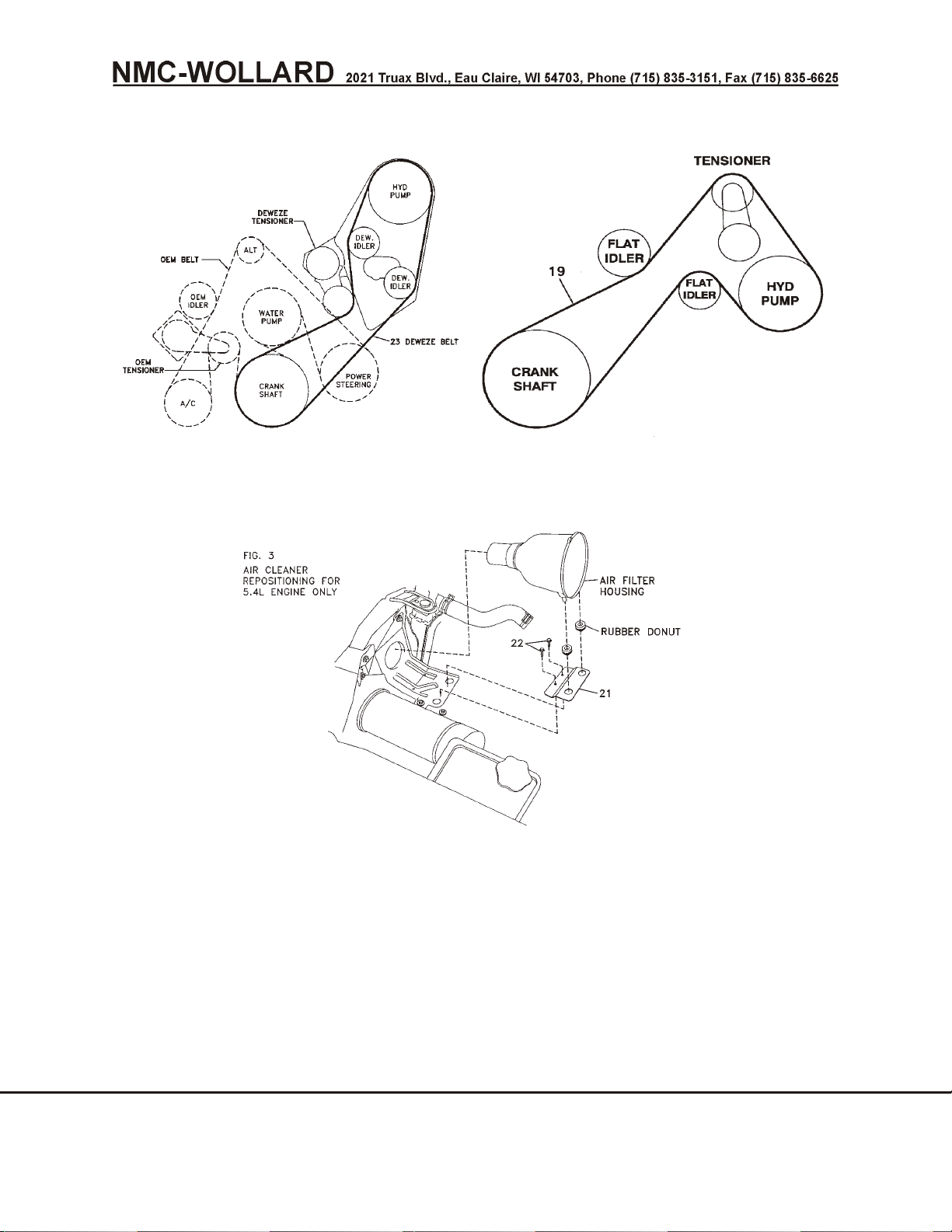
Truck Mounted Passenger Stair TMPS-200 Manual No. 307559
PRIOR TO SN 718
SN 718 & AFTER
FIGURE 8. F350 V8/GAS CLUTCH PUMP INSTALLATION
3.12 F350 V8/Gas Clutch Pump Installation
1. Disconnect battery and drain the radiator.
2. Remove the upper radiator hose. Make note as to which end is which, as
it will be turned around when it is installed later.
SEPTEMBER 30, 2008 CHAPTER 2 MAINTENANCE
PAGE 20 3 REMOVAL AND INSTALLATION
 Loading...