

Page 1
Instruction Manual
PCM F
PCM F - Rev. 00 as of 24.10.2007 Page 1
Instruction Manual for portable
Flow Measurement System PCM F
incl. accompanying Sensors
(Original Instruction Manual – German)
valid as of Software Revision No. 1.12
Page 2

Instruction Manual
PCM F
PCM F - Rev. 00 as of 24.10.2007 Page 3
Translation
If the device is sold to a country in the European Economic Area (EEA)
this instruction handbook must be translated into the language of the
country in which the device is to be used.
Should the translated text be unclear, the original instruction handbook
(German) must be consulted or the manufacturer contacted for
clarification.
Copyright
No part of this publication may be reproduced, transmitted, sold or
disclosed without prior permission. Damages will be claimed for violations.
All rights reserved.
Names
The use of general descriptive names, trade names, trademarks and the
like in this handbook does not entitle the reader to assume they may be
used freely by everyone. They are often protected registered trademarks
even if not marked as such.
Page 3

Instruction Manual
Page 4 PCM F - Rev. 00 as of 24.10.2007
1 Contents
1.1 Table of Contents
PCM F
1 Contents ............................................................................... 4
1.1 Table of Contents .......................................................................... 4
2 Overview and use in accordan ce with the r equ irem ent s . 7
2.1 Overview ........................................................................................ 7
2.2 Use in accordance with the requirements ..................................... 9
2.3 Specifications .............................................................................. 10
2.3.1 Transmitter .................................................................................. 10
2.3.2 Active Doppler sensor ................................................................. 11
2.3.3 Air-ultrasonic sensor .................................................................... 12
2.3.4 Accessories (optional) ................................................................. 13
3 General Notes on Safety and Danger ............................... 14
3.1 Danger Notes .............................................................................. 14
3.1.1 General Danger Signs ................................................................. 14
3.1.2 Special Danger Notes.................................................................. 14
3.2 Device Identification .................................................................... 15
3.3 Installation of Spare Parts and Parts subject to Wear and Tear . 15
3.4 Shutdown Procedure ................................................................... 16
3.5 User’s Responsibilities ................................................................ 16
4 Functional Principle .......................................................... 17
4.1 General ........................................................................................ 17
4.2 Level Measurement using Press ure ............................................ 18
4.3 Flow Velocity Detection ............................................................... 18
4.4 Unit Versions ............................................................................... 19
5 Storing, Delivery and Transport ....................................... 22
5.1 Receipt ........................................................................................ 22
5.1.1 Delivery ........................................................................................ 22
5.2 Storing ......................................................................................... 22
5.3 Transport ..................................................................................... 23
5.4 Return .......................................................................................... 23
6 Installation .......................................................................... 24
6.1 General ........................................................................................ 24
6.2 Transmitter Installation and Connection ...................................... 24
6.2.1 Enclosure Dimensions ................................................................. 25
6.3 Sensor Installation and Connection ............................................. 26
6.3.1 Sensor dimensions ...................................................................... 26
6.3.2 Selecting Sensor Positions and Calming Sections ..................... 28
6.3.3 Sensor Installation ....................................................................... 33
6.3.4 Pipe Mounting System................................................................. 38
6.3.5 Sensor Connection ...................................................................... 42
6.3.6 Peripheral Equipment Connection ............................................... 44
6.3.7 Connector-Box ............................................................................. 45
6.4 PCM F Power Supply .................................................................. 46
6.4.1 (Rechargeable) Batteries............................................................. 46
6.4.2 Mains Connection ........................................................................ 48
Page 4

Instruction Manual
PCM F
PCM F - Rev. 00 as of 24.10.2007 Page 5
6.4.3 Alternative Power Supply ............................................................ 48
7 Initial Start-Up .................................................................... 49
7.1 General ........................................................................................ 49
7.2 Keypad ........................................................................................ 50
7.3 Display ......................................................................................... 51
7.4 Operation Basics ......................................................................... 53
7.5 Measurement and Display Functions .......................................... 54
7.5.1 Display Functions in Memory Mode ............................................ 54
7.5.2 Display Functions without Memory Mode.................................... 55
8 Parameter Setting .............................................................. 56
8.1 Parameter Setting Quick Guide ................................................... 56
8.2 Parameter Setting Basics ............................................................ 57
8.3 Operation Mode (RUN)............................................................... 58
8.4 Display Menu (EXTRA) .............................................................. 63
8.5 Parameter Menu (PAR) ............................................................... 65
8.5.1 Parameter Menu "Measurement Place“ ...................................... 66
8.5.2 Parameter Menu "Level “ ............................................................. 71
8.5.3 Parameter Menu “Flow Velocity“ ................................................. 74
8.5.4 Parameter Menu “Analog Inputs“ ................................................ 75
8.5.5 Parameter Menu "Digital Inputs“ ................................................. 77
8.5.6 Parameter Menu "Analog Outputs“ ............................................. 77
8.5.7 Parameter Menu “Digital Outputs“ ............................................... 79
8.5.8 Parameter Menu “Setup Parameter“ ........................................... 82
8.5.9 Parameter Menu "Storage Mode “ ............................................... 83
8.5.9.1 Data Structure on Memory Card ................................................. 88
8.6 Signal Input / Output Menu (I/O) ................................................. 89
8.6.1 I/O Menu “Analog Inputs” ............................................................ 89
8.6.2 I/O Menu “Digital Inputs”.............................................................. 90
8.6.3 I/O Menu “Analog Outputs” ......................................................... 90
8.6.4 I/O Menu “Digital Outputs” ........................................................... 90
8.6.5 I/O Menu “Sensors” ..................................................................... 91
8.6.6 I/O Menu “Memory Card”............................................................. 92
8.6.7 I/O Menu „System” ...................................................................... 95
8.7 Calibration and Calculation Menu (CAL) .................................... 96
8.7.1 Cal Menu “Level“ ......................................................................... 97
8.7.2 Cal Menu "Velocity“ ..................................................................... 99
9 Parameter Tree................................................................. 102
10 Troubleshooting .............................................................. 109
11 Table of Resistiveness .................................................... 112
11.1 Resistiveness Legend ............................................................... 114
12 Maintenance and Cleaning ............................................. 115
12.1 Sensors ..................................................................................... 115
12.1.1 Doppler Sensor with Pressure Measurement ........................... 116
12.1.2 Air-Ultrasonic Sensor ................................................................. 117
12.2 Transmitter ................................................................................ 118
12.2.1 Enclosure ................................................................................... 118
12.2.2 Batteries .................................................................................... 119
13 Dismantling/Disposal ...................................................... 119
Page 5

Instruction Manual
PCM F
Page 6 PCM F - Rev. 00 as of 24.10.2007
14 Table “Manning - Strickler Coefficients“ ....................... 119
15 Table of Pictures .............................................................. 120
16 Index ................................................................................. 123
17 EC Declaratin of Conformity ........................................... 126
Page 6
Instruction Manual
PCM F
PCM F - Rev. 00 as of 24.10.2007 Page 7
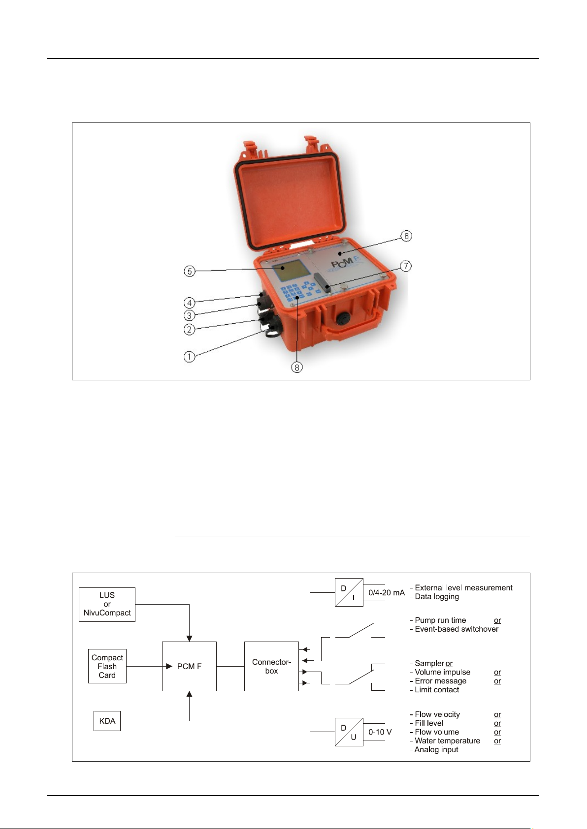
2 Socket for connection of active Doppler sensor
3 Socket for connection of air-ultrasonic sensor Type OCL or
4 Socket for combined mains adapter / battery charger
5 Display
6 (Rechargeable) battery compartment
7 Memory card slot with cover
8 Programming keys
2 Overview and use in accordance with the requirements
2.1 Overview
1 Multifunctional socket to connect either Connector-Box,
active digital input, 0/4-20mA input signal or 0-10V
voltage output and relay output t
external level measurement 4-20mA (such as NivuCompact)
Fig. 2-1 Overview PCM F
Fig. 2-2 Possible combinations
Page 7
Instruction Manual
PCM F
Page 8 PCM F - Rev. 00 as of 24.10.2007
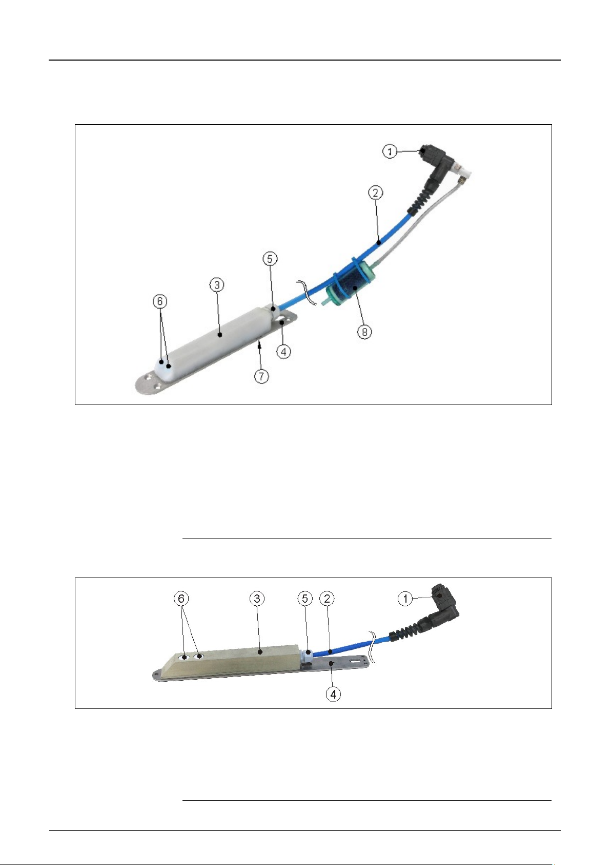
2 Sensor cable
3 Sensor body
4 Ground plate
5 Cable gland
6 Sensor for flow velocity measurement
7 Sensor for Doppler level measurement
8 Sensor for level measurement using pressure
9 Air filter
2 Sensor cable
3 Sensor body
4 Ground plate
5 Cable gland
6 Sensors for level measurement using air-ultrasonic
The Connector-Box shall be used only if more than one input or output has been
connected to the multifunctional socket of the PCM F simultaneously.
1 Plug with spigot nut, IP68
Fig. 2-3 Overview active Doppler sensor
1 Plug with spigot nut, IP68
Fig. 2-4 Overview air-ultrasonic sensor
Page 8

Instruction Manual
PCM F
PCM F - Rev. 00 as of 24.10.2007 Page 9
2.2 Use in accordance with the requirements
The measurement device Type PCM F as well as the accompanying sensors
are designed to temporarily measure flow of slight to heavy polluted media in
part filled and full sewers, pipes and other channels. External data can be
detected and recorded as well. Additionally it is possible to drive external
peripheral units optionally.
The unit is designed to be powered independent from mains by using either
rechargeable batteries or standard batteries. On the other hand the unit can be
powered from mains by using the combined power pack / battery charger.
Measured and recorded data is going to be saved on a non-volatile,
exchangeable storage medium.
Please necessarily observe the maximum permissible limit values as specified in
chapter 2.3 Specifications. Any cases varying from these conditions without
being approved by NIVUS GmbH in writing are entirely at owner’s risk.
The device is exclusively intended to be used for purposes as described
above.
Modifying or using the devices for other purposes without the written consent
of the manufacturer will not be considered as use in accordance with the
requirements.
Damages resulting from this are left at user’s risk.
Page 9
Instruction Manual
Page 10 PCM F - Rev. 00 as of 24.10.2007
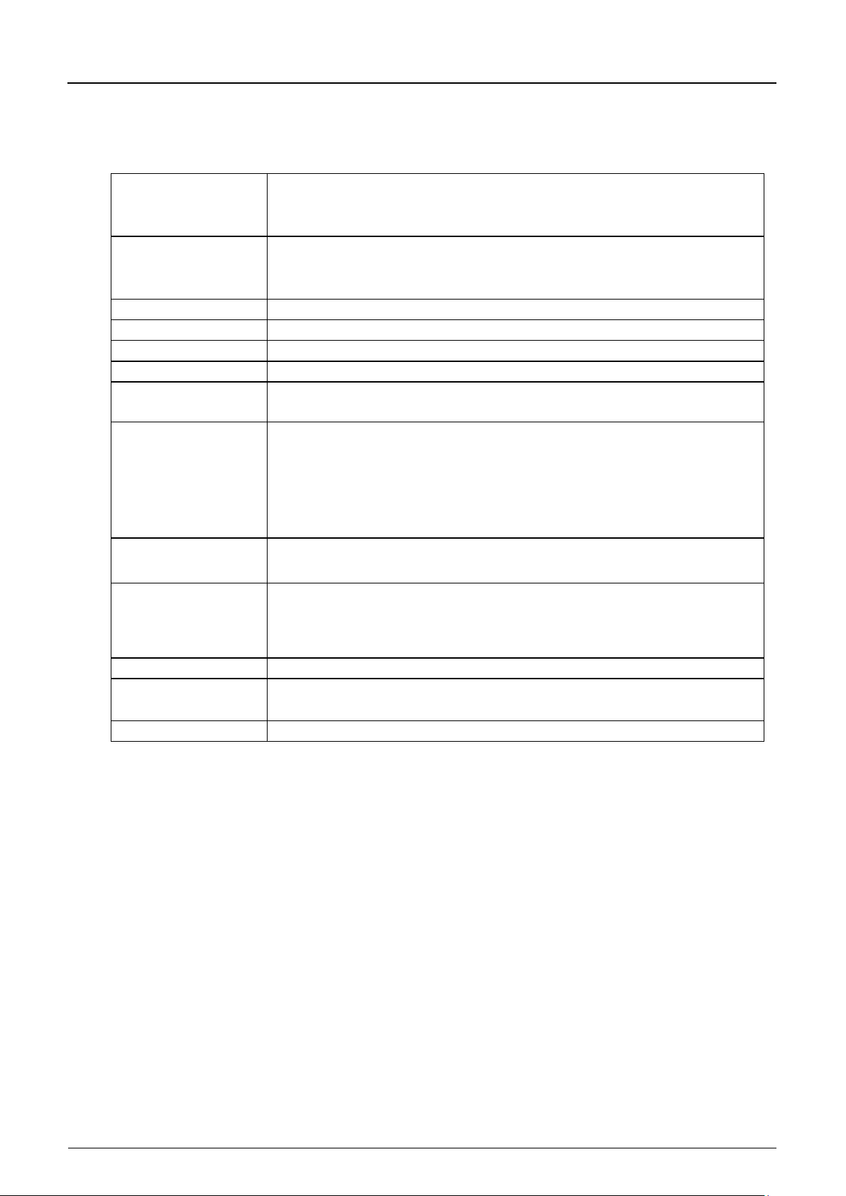
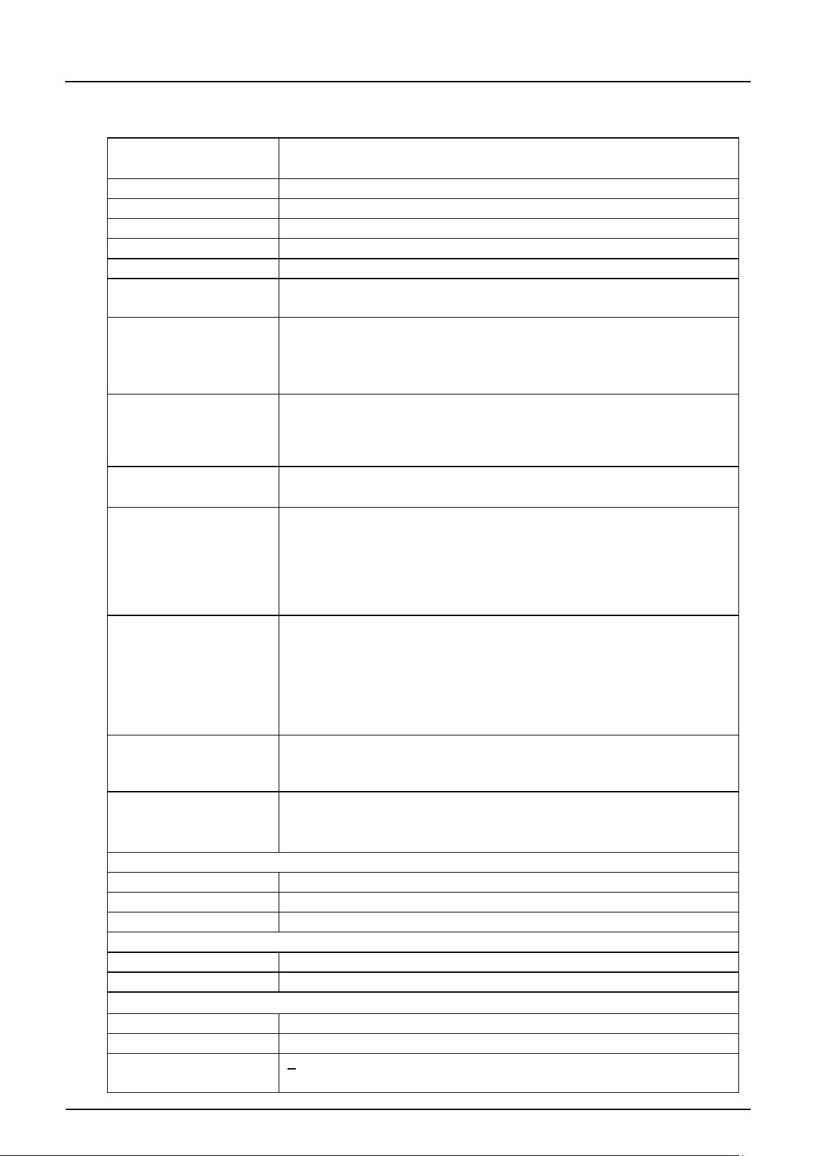
Power supply
rechargeable lead gel battery: 12V/12 Ah
Enclosure
material: Polypropylene, impact resistant
Operating temperature
-20°C to +50°C (-4°F to 122°F)
Storing temperature
-30°C to +70°C (-22°F to 171°F)
Max. humidity
90 %, non-condensing
Display
back-lit graphic display, 128 x 128 pixel
Operation
18 keys, menus in German, English, French, Italian, Czech, Spanish, Polish
Sockets (IP68)
1 x 4 – 20 mA for external level (active 2-wire sensor) or
Inputs via
1 x active digital input, supply voltage 3.3 V DC
Outputs via
1 x relay (SPDT)
Memory cycle
1 to 60 minutes, cyclical or event-based
Data memory
externally on plug-in memory card (CF) up to 128 MB
Data transmission
via plug-in memory card
2.3 Specifications
2.3.1 Transmitter
multifunctional socket
PCM F
-
- battery compartment for 12 LR20 standard batteries 1.5V (Type LR20)
- power pack 100 – 240 V AC; 50/60 Hz
-
- weight: approx. 2.0 kg (4.41 lbs, without sensor and batteries)
- protection: IP67 if lid is closed and locked
and Danish
-
1 x active air-ultrasonic sensor Type OCL for level measurement
- 1 x intelligent Doppler sensor Type KDA for flow velocity and level
measurement
- 1 x multifunctional socket for digital and analog inputs and outputs
- 1 x socket for combined power pack and battery charger
-
- 1 x analog input, 0/4 – 20 mA (passive)
multifunctional socket
-
switching capacity: 250 V AC/30 V DC, 5 A
switching frequency: 5 Hz
- 1 x voltage output 0 – 1 0 V
-
- internal RAM, 8 MB
Page 10
Instruction Manual
PCM F
PCM F - Rev. 00 as of 24.10.2007 Page 11
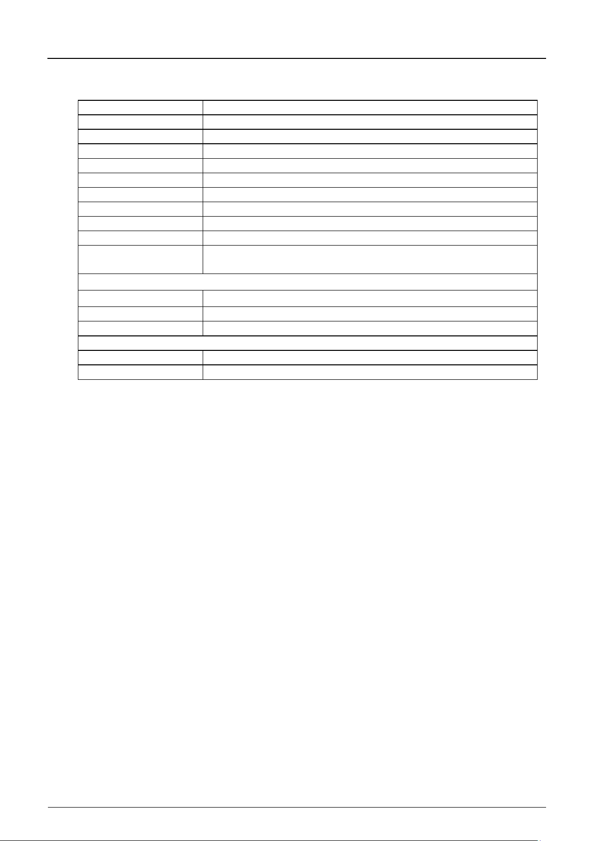
Measurement principle
Doppler measurement principle (flow velocity)
Measurement frequency
wedge sensors 1MHz, pipe sensors 750 kHz
Protection
IP 68
Ex approval (optional)
II 2 G EEx ib IIB T4
Operating temperature
-20° C to +50° C (-4° F to 122° F), +40° C (104° F) in Ex Zone 1
Storing temperature
-30° C to +70° C (-22° F to 158° F)
Operational pressure
max. 4 bar (58 psi) (combi sensor with pressure measurement cell max.
Cable length
10/15/20/30/50/100 m (33/49.2/66/98.4/164/328 ft) pre-configured,
Cable types
combi sensor with pressure measurement:
Outer cable diameter
combi sensor with pressure measurement: 9.75 mm ±0.25 mm
Sensor connection
pre-configured cable end for connection to PCM F,
Sensor types
Constructions
wedge-shaped sensor for installation on channel bottom
Medium-contacting
wedge sensor: Polyurethan e, stai nles s steel 1.45 71, P VDF, PA
Flow velocity measurement
Measurement range
-600 cm/s bis +600 cm/s (-19.7 ft/s to +19.7 ft/s)
Zero point drift
absolutely stable zero point
Sonic beam
±5 degrees
Temperature measurement
Measurement range
-20° C to +60° C (-4° F to 140° F)
Accuracy
±0.5 K
Level measurement - pressure
Measurement range
0 to 350 cm (0 to 11.5 ft)
Zero point drift
max. 0.75 % of final value (0-50° C / 32-122° F)
Accuracy
<0.5 % of final value
2.3.2 Active Doppler sensor
materials
-
- piezo-resistive pressure measurement (level measurement) optional
1 bar (14.5 psi))
extendable to up to max. 250 m (820 ft);
using sensors with integrated pressure measurement cell requires to use
a pressure compensation element after a cable length of 30 m (98.4 ft)
-
LiYC11Y 2x1.5 + 1x2x0.34 + PA 1.5/2.5
- sensors without pressure measurement:
LiYC11Y 2x1.5 + 1x2x0.34
-
- sensors without pressure measurement: 8.40 mm ±0.25 mm
-
cable types „K“ and „L“
- cable with plug for connection to PCM F,
for sensors without pressure measurement, cable type „S“
- cable with plug and replaceable filter element for connection to
PCM F, for sensors with pressure measurement, cable type „F“
- flow vel oci t y sensor with v-measurement using Doppler measurement
principle and temperature measurement to compensate temperature
effects on sound velocity
- combi sensor with flow velocity sensor using Doppler measurement
principle; level measurement using pressure and temperature
measurement to compensate temperature effects on sound velocity
(only wedge sensor)
-
- pipe sensor for installation in pipes using cutting ring screw joint and
nozzle
-
- pipe sensor: stainless steel 1.4571, Polyurethane
- FEP-coated cable (optional for PCM F)
(standing medium)
Page 11
Instruction Manual
Page 12 PCM F - Rev. 00 as of 24.10.2007
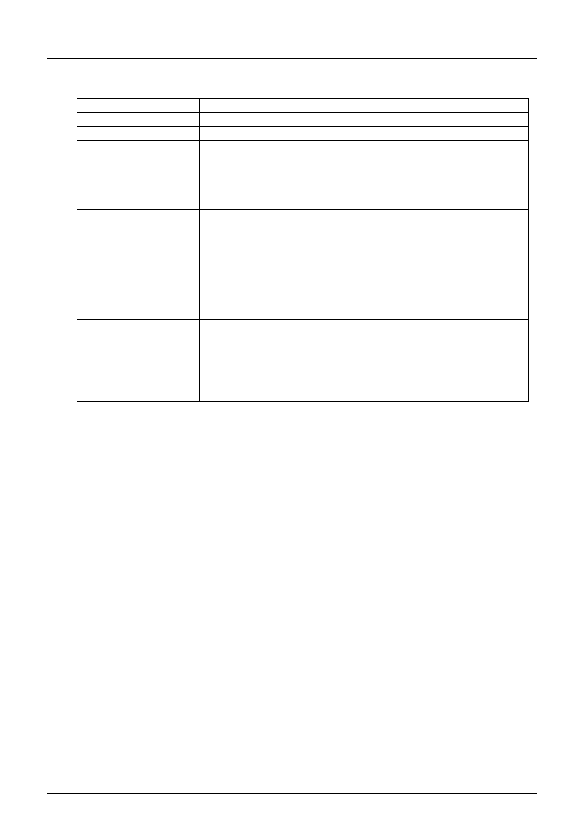
Measurement principle
ultrasonic transit time
Measurement frequency
120 kHz
Protection
IP68
Operating temperature
-20° C to +50°C (-4° F to 122° F)
Storing temperature
-30° C to +70°C (-22° F to 158° F)
Operational pressure
max. 1 bar (14.5 psi)
Cable length
10/15/20/30/50/100 m (33/49.2/66/98.4/164/328 ft) pre-configured
Cable type
LiYC11Y 2x1.5 + 1x2x0.34
Outer cable diameter
8.4 mm ±0.25 mm (0.33 in ±0.01 in)
Construction
wedge sensor for installation in channel vertex
Medium-contacting
Polyurethane, stainless steel 1.4571, PPO GF30, PA
Level measurement
Measurement range
0 to 200 cm (0 to 6.56 ft)
Dead zone
10 cm (3.94 in)
Accuracy
< ±5 mm (±0.19 in)
Temperature measurement
Measurement range
-20° C to +50° C (-4° F to 122° F)
Accuracy
±0.5 K
2.3.3 Air-ultrasonic sensor
materials
PCM F
Page 12
Instruction Manual
PCM F
PCM F - Rev. 00 as of 24.10.2007 Page 13
Memory card
type: Compact Flash Card; capacity: 128 MB
Read-out adapter
adapter for PCMCIA interfaces, mainly for read-out via Laptop / Notebook
Card reader
with USB interface for PC connection
Connector-Box
for simultaneous connection of more than one output or input to the
Power supply
rechargeable lead gel battery: 12V/12 Ah
Pipe mounting system
for temporary, non-permanent clamping installation of wedge sensors
Suspension bracket with
to fasten the PCM F on access ladders or similar
Power pack / battery
combined battery charger for rechargeable lead gel batteries or for direct
Evaluation software
type: NivuDat for Windows NT / 2000 / XP for data read-out, data
External battery box
external battery box for connection to PCM F via charger socket
Connection cables
there are numerous pre-configured cables for connection of peripheral
2.3.4 Accessories (optional)
eyelet
PCM F multifunctional socket
rechargeable lead gel battery: 12V/26 Ah, for use in external battery box
battery compartment for 12 LR20 standard batteries 1.5V
(Doppler sensor and air-ultrasonic sensor) in pipes DN 200 – 800
(diameters from 7.9 in to 31.5 in) and egg profiles up to h = 600 mm
(height = 23.6 in)
charger
mains operation, 100-240 V AC/50-60 Hz; IP 40
evaluation, generation of hydrographs, average values, hour, day and
month totals and more
units available. Please refer to the respective chapters for details
Page 13
Instruction Manual
Page 14 PCM F - Rev. 00 as of 24.10.2007
3 General Notes on Safety and Danger
3.1 Danger Notes
3.1.1 General Danger Signs
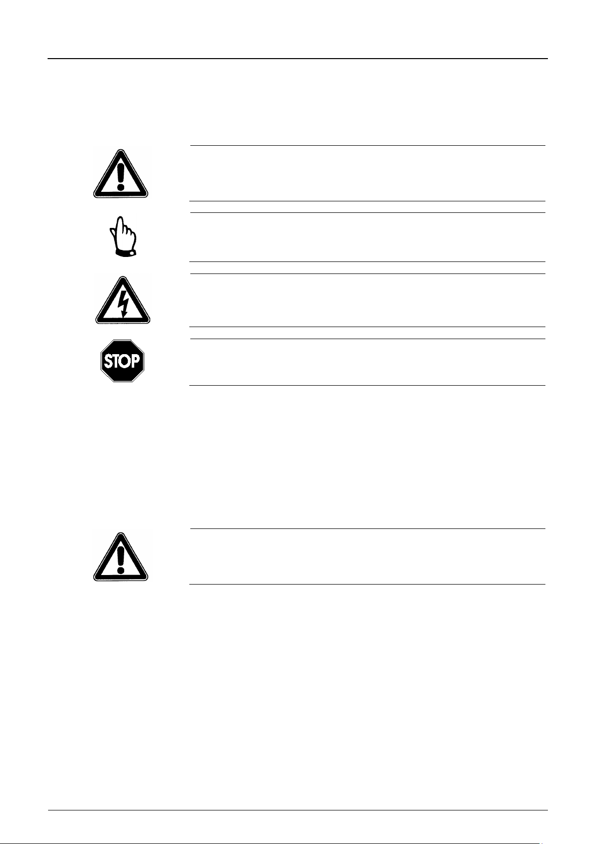
Cautions
are framed and labelled with a warning triangle.
Notes
are framed and labelled with a “hand“.
Danger by electric voltage
is framed and labelled with the Symbol on the left..
PCM F
Warnings
are framed and labelled with a “STOP“-sign.
For connection, initial start-up and operation of the PCM F the following
information and higher legal regulations (e.g. in Germany VDE), such as Exregulations as well as safety requirements and regulations in order to avoid
accidents, must be adhered to.
All operations, which go be yon d steps re gar d ing inst al l atio n, connec ti on or
programming the unit are allowed to be carried out by NIVUS staff only due to
reasons of safety and guarantee.
3.1.2 Special Danger Notes
Please note that due to the operation in the waste water field transmitter,
sensors and cables may be loaded with hazardous disease germs. Respective
precautionary measures must be taken to avoid damage to one’s health.
Page 14
Instruction Manual
PCM F
PCM F - Rev. 00 as of 24.10.2007 Page 15
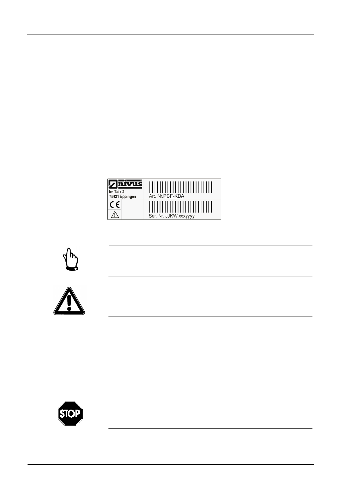
3.2 Device Identification
The instructions in this manual apply only for the type of device indicated on the
title page.
The nameplate is fixed on the reverse side of the device and contains the
following:
- name and address of manufacturer
- CE label
- type and serial number
- year of manufacture
It is important for queries and replacement part orders to specify type, year of
manufacture and serial number (Article no. if necessary). This ensures correct
and quick processing.
Fig. 3-1 PCM F nameplate
This instruction manual is a part of the device and must be available for users
at any time.
The safety instructions contained within must be followed.
It is strictly prohibited to disable the safety devices or to modify the way they
work.
3.3 Installation of Spare Parts and Parts subject to Wear and Tear
We herewith particularly emphasize that replacement parts or accessories,
which are not supplied by us, are not certified by us, too. Hence, the installation
and/or the use of such products may possibly be detrimental to the device’s
ability to work.
Damages caused by using non-original parts and non-original accessories are
left at user’s risk.
Using spare parts / parts subject to wear and tear (such as rechargeable
batteries, filters or similar) which are not licensed by NIVUS will invalidate any
warranty claims.
Page 15

Instruction Manual
Page 16 PCM F - Rev. 00 as of 24.10.2007
3.4 Shutdown Procedure
For maintenance, cleaning and repair purposes (authorized staff personnel
only) the device has to be disconnected from batteries / mains.
3.5 User’s Responsibilities
In the EEA (European Economic Area) national implementation of the
framework directive 89/391/EEC and corresponding individual directives, in
particular the directive 89/655/EEC concerning the minimum safety and health
requirements for the use of work equipment by workers at work, as amended,
are to be observed and adhered to.
In Germany the Industrial Safety Ordinance must be observed.
The customer must (where necessary) obtain any local operating permits
required and observe the provisions contained therein. In addition to this, he
must observe local laws and regulations on
PCM F
- personnel safety (accident prevention regulations)
- safety of work materials and tools (safety equipment and maintenance)
- disposal of products (laws on wastes)
- disposal of materials (laws on wastes)
- cleaning (cleansing agents and disposal)
- environmental protection.
Connections
Before operating the device the user has to ensure, that the local regulations
(e.g. for operation in channels) on installation and initial start-up are taken into
account, if this is both carried out by the user.
Page 16
Instruction Manual
PCM F
PCM F - Rev. 00 as of 24.10.2007 Page 17
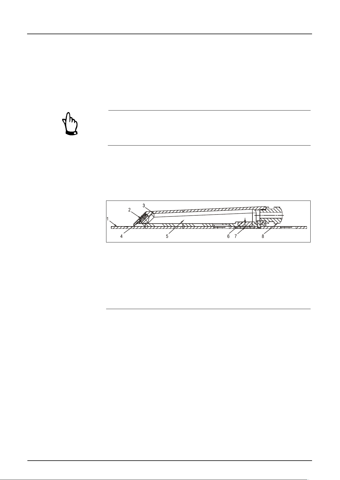
2 Acoustic coupling layer
3 Temperature sensor
4 Flow velocity sensor
5 Electronics
6 Pressure measurement cell
7 Duct to pressure measurement
8 Cable gland
4 Functional Principl e
4.1 General
The PCM F is a portable measurement system for non-permanent flow
measurement and data logging in slight to heavy polluted media of a wide
variety of compositions. The system is designed for use in part filled and full
channels, sewers and pipes with various shapes and dimensions.
The measurement method is based on the ultrasound reflection principle.
Hence, it is indispensable for the system’s capability to work that the water
contains particles which are able to reflect the ultrasonic signal sent by the
sensor (dirt particles, gas bubbles or similar).
The PCM F utilises an active Doppler sensor Type KDA. Flow velocity
evaluation by using a histogram filter (assessment of investigated frequency
distribution) is carried out directly in the sensor.
The PCM F flow velocity sensor can be combined with a sensor-integrated
pressure measurement cell for hydrostatic level measurement.
1 Ground plate
Fig. 4-1 Construction of combi sensor Type “KDA“ for
installation on ground
Page 17

Instruction Manual
Page 18 PCM F - Rev. 00 as of 24.10.2007
4.2 Level Measurement using Pressure
The combi sensor may additionally include a hydrostatic level measurement
depending on the type of sensor selected.
The piezo-resistive pressure sensor operates according to the relative pressure
principle, i.e. the pressure of the standing water column above the sensor is
direct proportional to the flow level. This sensor enables to determine flow levels
even if the combi sensor is installed out of the centre.
During initial start-up procedure, the pressure sensor is going to be adjusted by
entering a manually investigated reference value. The level caused by the
sensor installation position is going to be added as well.
4.3 Flow Velocity Detect io n
The flow velocity sensor operates according to the continuous Doppler principle
(CW-Doppler) using 2 built-in piezo crystals with a slope of 45°. The crystal
surfaces are arranged parallel to the slope of the flow velocity sensor. One of the
crystals continuously operates as ultrasonic transmitter, the other one as
receiver detecting the reflected ultrasonic signal.
The potting compound used enables acoustic coupling of the high-frequency
ultrasonic signal between piezo crystal/potting compound and potting
compound/medium. Due to that reason an ultrasonic signal in an angle of 45° is
sent permanently against the flow direction of the medium to be measured. As
soon as the signal hits dirt particles, gas bubbles or similar a portion of the sonic
energy is reflected, being subsequently converted into an electric signal by the
receiving crystal.
Caused by the movement of the reflecting particles in relation to the acoustic
source the frequency of the ultrasonic signal is shifted. The resulting frequency
shift is directly proportional to the particles’ movement within the medium and
hence represents the flow velocity.
The sensor evaluates the received reflection signal in relation to the frequency
shift, converting it to be sent to the transmitter.
A frequency mixture Due to varying velocities within the flow profile, vorticity,
rotation of single reflecting particles, surface waves etc. a frequency mixture is
emerging. This mixture is going to be evaluated directly in the sensor, using
special algorithms to obtain the average flow velocity. The frequency mixture is
indicated on the transmitter display under RUN / Graph (see Fig. 8-3).
Since it is not possible to spatially allocate the measured flow velocities due to
the physical measurement principle, it is necessary to calibrate each
measurement using a second method which is based on a different physical
principle. In this case the VDI/VDE Directive 2640 is very helpful and important.
NIVUS recommends the portable meter Type >PVM/PD< as calibration
measurement or the NIVUS initial start-up service.
PCM F
Page 18
Instruction Manual
PCM F
PCM F - Rev. 00 as of 24.10.2007 Page 19
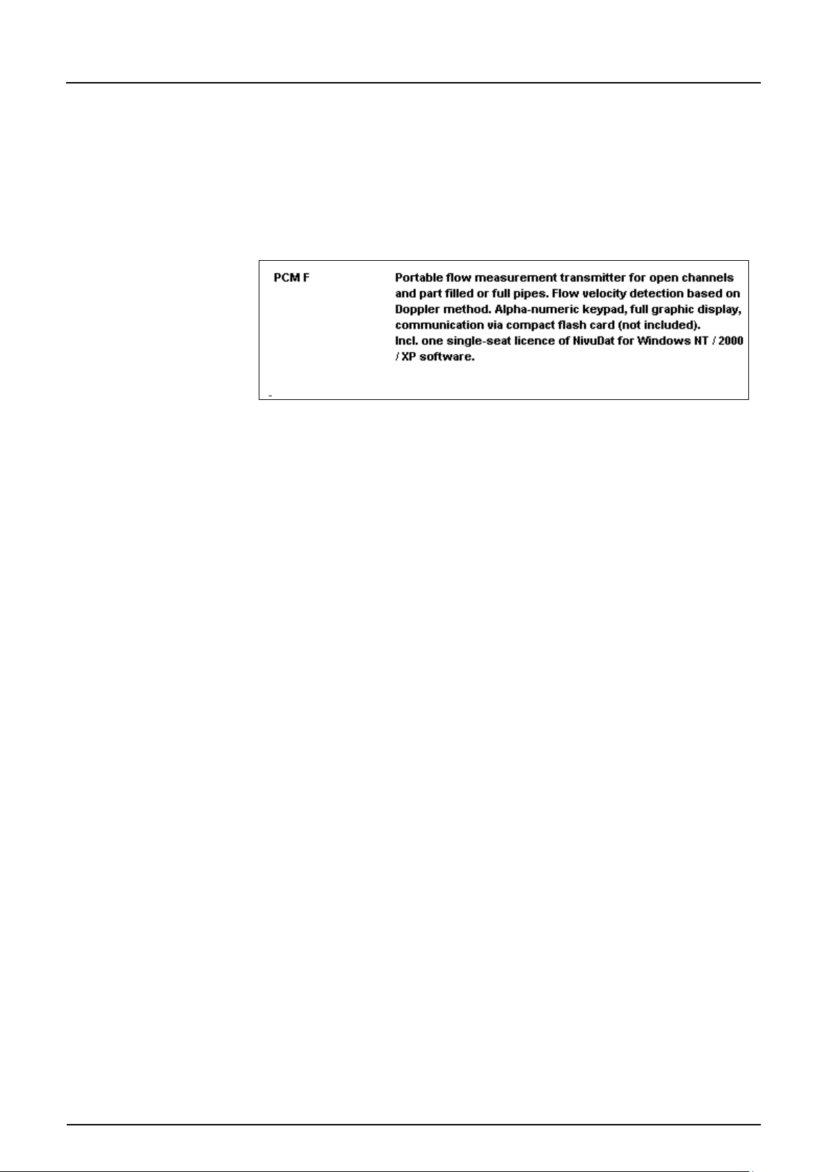
4.4 Unit Versions
Transmitter
The transmitter currently is manufactured in one version.
The unit version at hand can be seen from the article number on a weatherproof
label on the reverse side of the enclosure.
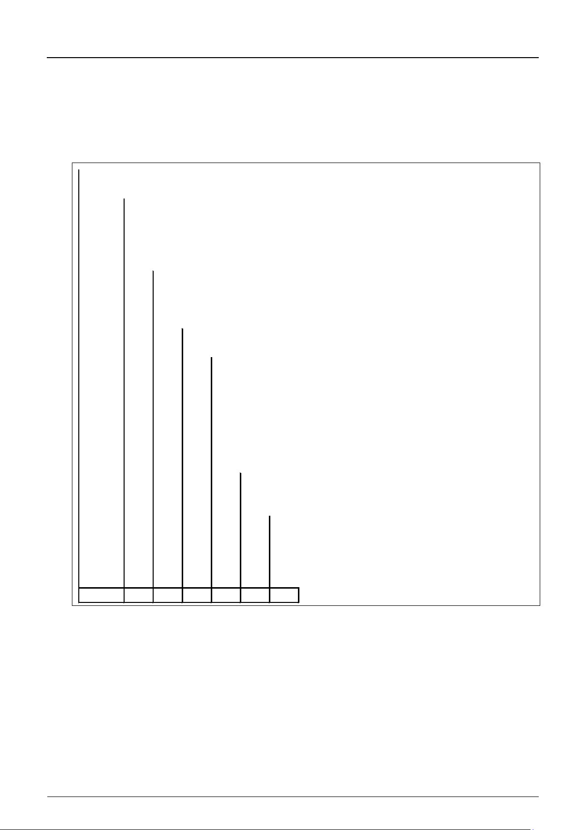
The unit type can be exactly specified from the type key.
Fig. 4-2 Type key for PCM F transmitter
Page 19
Instruction Manual
PCM F
Page 20 PCM F - Rev. 00 as of 24.10.2007
KDA
Compact Doppler active
Construction
K0
KP
R0
07
750 Khz, only for pipe sensor
10
1 MHz, only for wedge sensor
Approvals
0
none
Cable Length (max. 150 m / with pressure sensor up to 30 m possible)
10
10 m
15
15 m
20
20 m
30
30 m
50
50 m
99
100 m
XX
Special length upon request
S
F
Tube length
0
(only for wedge sensor)
2
20 cm (standard)
3
30 cm (minimum length for stop valve)
X
Pipe length in dm, price per dm
G
20 cm + extension thread
KDA-
Cable end, pre-configured, for Types K0 and R0
Cable end , pre-configured, for Type KP
Combi wedge sensor with integrated pressure measurement cell, suitable for
simultaneous measurement of flow velocity and level. For installation on channel
bottom or for fastening using the RMS 2 pipe mounting system
Pipe sensor for installation using G 1 1/2" screw thread
Transmitting Frequency
Sensor Connection
Wedge sensor for installation on channel bottom or
for fastening using the RMS 2 pipe mounting system
Active sensors for PCM F
The sensors are available in various constructions (wedge and pipe sensors)
and additionally vary in terms of cable lengths as well as various special
versions. The article number can be found on both ends of the cables (cable
sheath) as well as on the bottom of the ground plate.
Fig. 4-3 Type key for Doppler sensors
Page 20
Instruction Manual
PCM F
PCM F - Rev. 00 as of 24.10.2007 Page 21
OCL-L0
Active air-ultrasonic sensor
Construction
K
Wedge sensor
X
Special construction
Sensor Version
S
Standard version made of PPO, cable: PUR
X
Special construction
Transmitting Frequency
12
120 kHz
XX
Special construction
Approvals
0
none
E
Ex zone 1 (Attention: only for PCM Pro)
Cable Length, max. 150 m
10
10 m
15
15 m
20
20 m
30
30 m
50
50 m
99
100 m
XX
Special lengths upon request
Sensor Connection
S
Connection plug for PCM Pro, PCM 4 and PCM F
OCL-L0 S
Fig. 4-4 Type key for air-ultrasonic sensors
Page 21
Instruction Manual
Page 22 PCM F - Rev. 00 as of 24.10.2007
Transmitter:
max. temperature: +70° C (158° F)
Sensors:
max. temperature: +70° C (158° F)
Rechargeable
max. temperature: + 25° C (77° F)
5 Storing, Deliver y and Tra nsport
5.1 Receipt
Please check your delivery if it is complete and in working order according to
the delivery note immediately after receipt. Any damage resulting from transport
or transit shall be reported to the carrier instantly. An immediate, written report
must be sent to NIVUS GmbH Eppingen as well.
Please report any shortcoming due to delivery to your representative or directly
to NIVUS Eppingen within two weeks in writing.
Mistakes cannot be rectified later!
5.1.1 Delivery
The standard delivery of the PCM F measurement system contains:
- the instruction manual with the certificate of conformity. All required steps to
correctly install and to operate the measurement system are listed herein.
PCM F
5.2 Storing
- a PCM F transmitter
- an active sensor
- a rechargeable battery
- a memory card
- a power pack / battery charger
- a copy of evaluation software Type NivuDat for NT / 2000 / XP
Additional accessories depend ing on order . Pleas e ch ec k by using the delivery
note.
The following storing conditions shall be strictly adhered to:
min. temperature: - 30° C (-22° F)
max. humidity: 90 %, non-condensing
min. temperature: - 30° C (-22° F)
max. humidity: 100 %
battery:
min. temperature: + 5° C (41° F)
max. humidity: 60 %
Page 22
Instruction Manual
PCM F
PCM F - Rev. 00 as of 24.10.2007 Page 23
5.3 Transport
Remove the batteries from the PCM F and keep them in a frost-free place
before storing.
The measurement system shall be protected from corrosive or organic solvent
vapours, radioactive radiation as well as strong electromagnetic radiation.
Sensors and transmitters are designed for harsh industrial conditions. However
do not expose them to heavy shocks or vibrations.
Transportation must be carried out in the original packaging.
Please carry the PCM F by using the carrying handle. The unit shall not be
carried or suspended using the sensor cable!
5.4 Return
The units must be returned at customer costs to NIVUS Eppingen in the
original packaging.
Otherwise the return cannot be accepted!
Page 23
Instruction Manual
Page 24 PCM F - Rev. 00 as of 24.10.2007
6 Installation
6.1 General
PCM F
Before feeding the rated voltage to transmitter and sensor the installation must
be completed correctly. The installation shall be carried out by qualified
personnel only.
For use in accordance with the requirements – flow detection – and the further
use of the gained data it is necessary to have comprehensive knowledge
about hydraulic conditions. Please note that improper, faulty or unsuitable
installation as well as selecting unsuitable or hydraulically problematic
measurement places may lead to faulty or incomplete measurement values
which may be insufficient for further processing and editing. This is why the
installation should be carried out by authorized personnel only.
If required, NIVUS can organise any according training.
Further statutory standards, regulations and technical rulings have to be taken
into account.
6.2 Transmitter Installation and Connection
General
The place for transmitter installation shall be selected according to certain
criteria. Please strict ly avoi d:
- direct sunlight
- objects emitting heat (max. ambient temperature: +40° C (104° F))
- objects with strong electromagnetic fields (e.g. frequency converters)
- corrosive chemicals or gas
- mechanical shocks
- vibrations
- radioactive radiation
The PCM F shall be suspended into shafts or manholes only by using the
carrying handle and sufficient straps, ropes or similar.
It is not allowed to suspend the unit by using the sensor cable as this may lead
to cable breaks, leaky plug connections or the transmitter may be torn off and
even get lost.
The PCM F can be fixed on the carrying handle using an appropriate suspension
bracket (Art.-No.: PCM0 ZMSH A K01 000) or another sufficient device e.g. on
the access ladder of a manhole.
Before locking the enclosure lid please make sure that the sealing is not
damaged and clean. Debris and/or dirt shall be removed and the gasket shall
be greased again with silicone if required. Damages resulting from leakage or
defect sealing are not covered by the manuf act urer’s liability.
Page 24
Instruction Manual
PCM F
PCM F - Rev. 00 as of 24.10.2007 Page 25
271,820
249
175,5
3
2
4
1
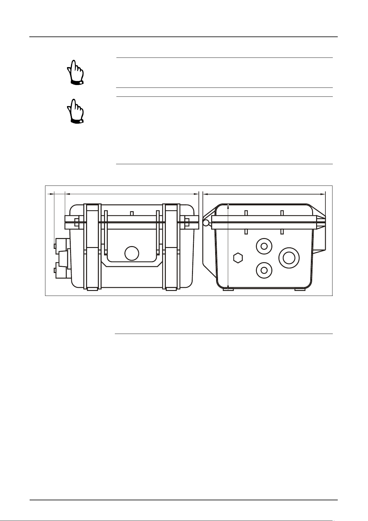
2 Socket for Doppler sensor
3 Socket for air-ultrasonic sensor / external level sensor
4 Socket for battery charger
6.2.1 Enclosure Dimensions
If placed in flood shafts or channels the transmitter must be secured in order
to prevent it from being washed away unintentionally (use suspension gear,
plastic or steel rope, chain or similar).
Sockets on the PCM F which are not required for measurement purposes,
sensors or data transmission have to be locked watertight before installation
by using the covers fastened on each socket. Otherwise the protection grade
of the entire unit is no longer guaranteed. Damages resulting from the
non-use of the covers are not covered by the manufacturer’s liability.
Covers damaged due to the use of force can be ordered from NIVUS at extra
costs.
1 Multifunctional socket
Fig. 6-1 PCM F enclosure dimensions and sensor connections
Page 25
Instruction Manual
Page 26 PCM F - Rev. 00 as of 24.10.2007
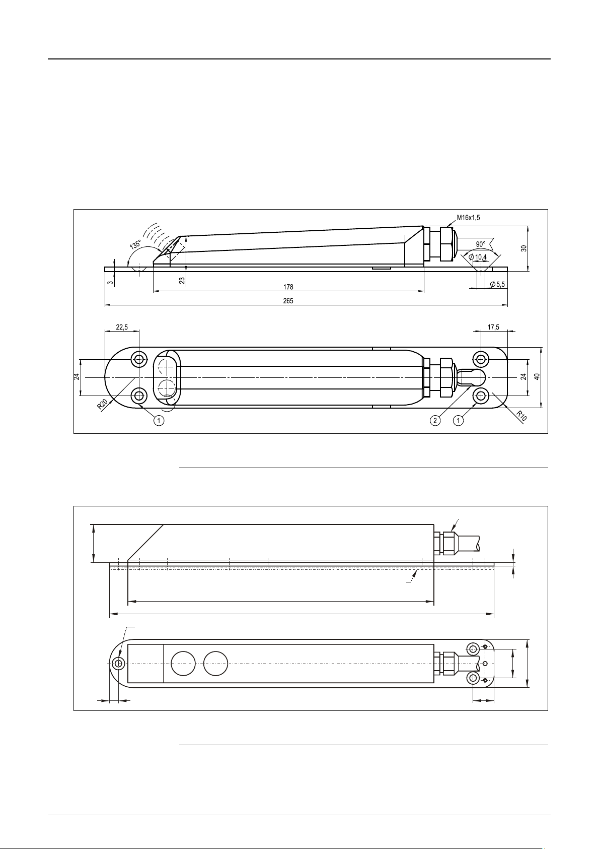
2 = Slotted holes for fastening on pipe mounting system
320,0
254,5
M16
3,0
31,0
X
24,0
40,0
17,5
7,5
Y
Y Three adapter plates are required for fastening on pipe mounting system
6.3 Sensor Installation and Connection
General
Take care to reliably and durably install the used sensors in a way that their
bevelled side with the integrated flow velocity sensor is looking exactly towards
the flow direction of the medium. Use corrosion-free fastening materials
exclusively!
6.3.1 Sensor dimensions
PCM F
1 = Countersunk holes according to DIN 66-5 for direct fastening
Fig. 6-2 Dimensions wedge-shaped active Doppler sensor (KDA)
X Countersunk holes according to DIN 74 - A m 5 for direct fastening
Fig. 6-3 Dimensions air-ultrasonic sensor
Page 26
Instruction Manual
PCM F
PCM F - Rev. 00 as of 24.10.2007 Page 27
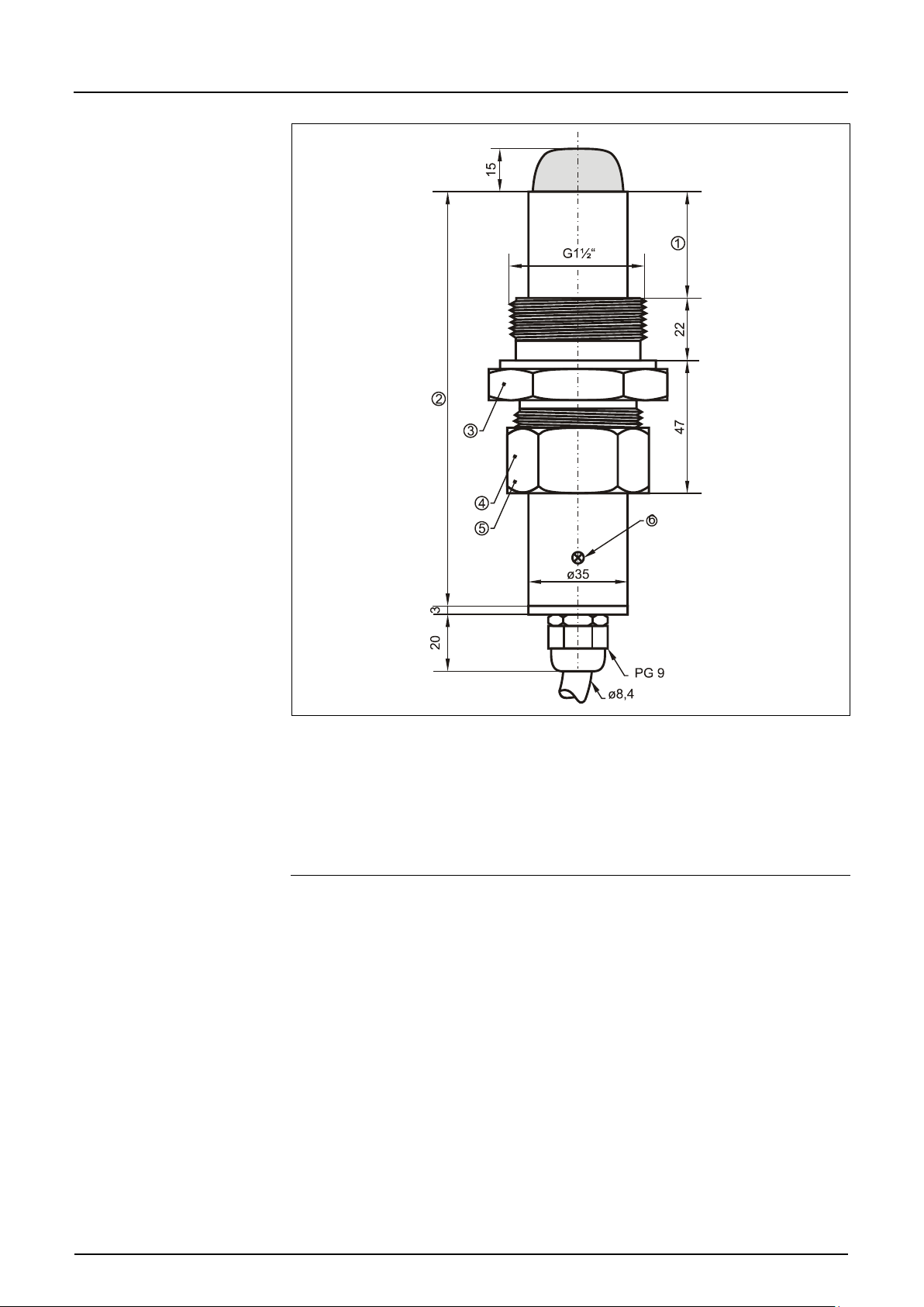
2 146 (standard) /
3 SW55
4 SW50
5 Nozzle
6 Screw 180° towards flow direction
1 Movable
300 (minimum length for retractable fitting / stop ball valve)
Fig. 6-4 Dimensions pipe sensor
Page 27
Instruction Manual
Page 28 PCM F - Rev. 00 as of 24.10.2007
Installation: normally centered Error: faulty measurement values
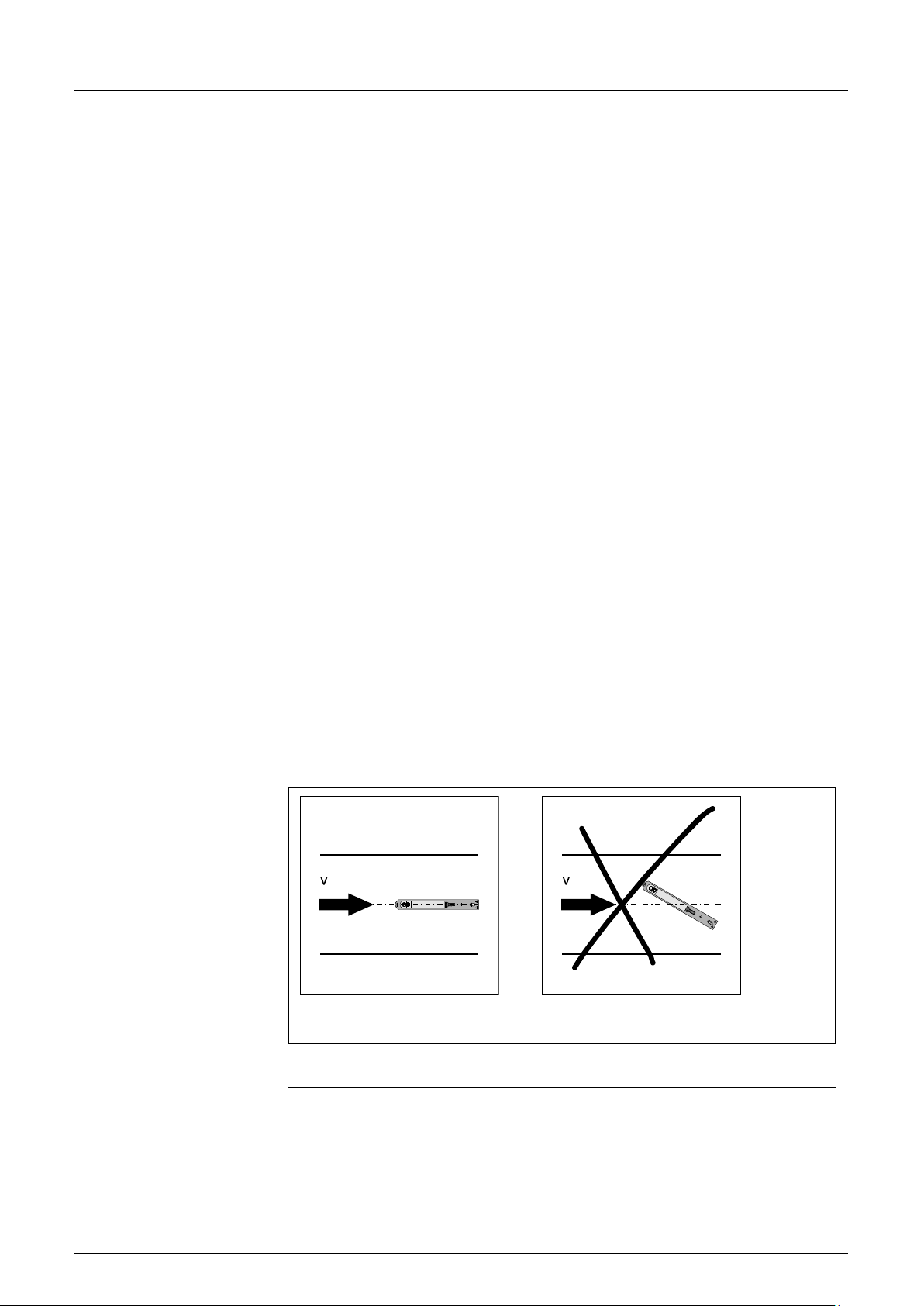
6.3.2 Selecting Sensor Positions and Calming Sections
Clearly defined, hydraulic conditions are absolutely necessary for an accurate
measurement. Falls, steps or obstructions, fittings, profile change of channels or
lateral supplies right in front of or behind the measurement point have to be
avoided!
- Measurement sections have to be selected in a way that there is no
sedimentation (sand, grit, sludge) arising under standard operating
conditions. Sedimentation is caused by low tractive forces within the flow
profile indica ting too low slopes or structural shortcoming (negative partial
slope) within the measurement section (please refer to ATV A 110).
- As from a filling level of approx. 80 % of the nominal diameter closed pipes
are tending to sudden short-term impoundage. To avoid pulsation within the
measurement section due to that circumstance construct the required
diameter in a way that the filling level never exceeds 80 % independent from
or Q
Q
min
- Avoid changes of slopes within the measurement section.
- The length of the approach channel shall be min. 5x nominal diameter, the
length of the discharge channel shall be min. 2x nominal diameter Longer
sections may be required however in case of disturbed hydraulic conditions
and distorted flow profiles resulting from these conditions.
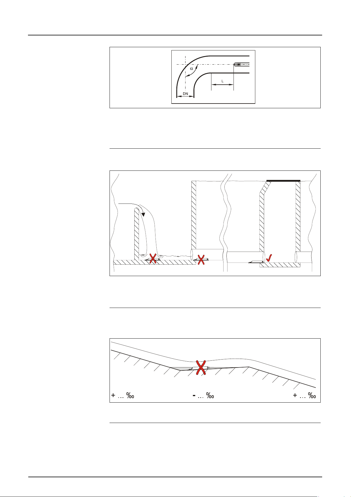
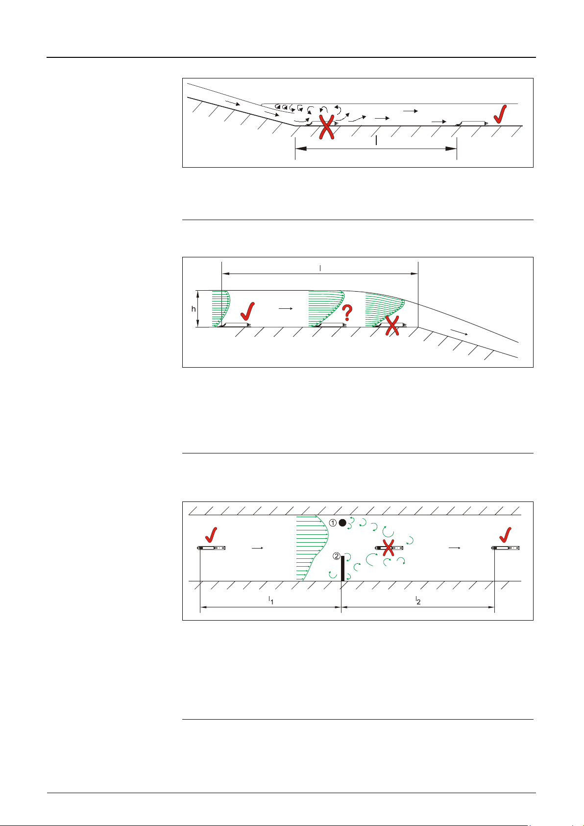
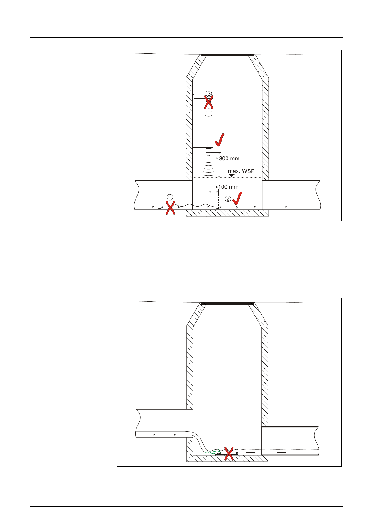
The drawings below (Fig. 6-7 to Fig. 6-13) give an example of appropriate, illsuited and problematic applications. They serve to give a rough idea on
sufficient measurement places as well as on critical hydraulic conditions which
might occur.
In case of being uncertain regarding choice or assessment of planned
measurement sections please send your drawings/photos and contact your
representative or the flow department at NIVUS GmbH in Eppingen.
in case of standard discharge (2 QTW).
max
PCM F
Fig. 6-5 Sensor adjustment
Page 28
Instruction Manual
PCM F
PCM F - Rev. 00 as of 24.10.2007 Page 29
v ≤ 1m/s (3.28 ft/s) v > 1m/s (3.28 ft/s)
α ≤15° L ≥ min. 3x diam. L ≥ min. 5x diam.
α ≤45° L ≥ min. 5x diam. L ≥ min. 10x diam.
α ≤90° L ≥ min. 10x diam. L ≥ min. 15-20x diam.
Fig. 6-6 Sensor position behind curves or elbows
= Error! Indefinable flow conditions
= Sufficient distance to obtain straight flow
(10 ... 50 x diameter depending on application)
Fig. 6-7 Overflow channel or fall - error caused by indefinable flow
conditions
= Error!
Risk of silting-up / sludge accumulation caused by negative slope
Fig. 6-8 Negative slope – risk of silting-up
Page 29
Instruction Manual
PCM F
Page 30 PCM F - Rev. 00 as of 24.10.2007
max
= Error! Alternation of slope = alternation of flow profile
= Distance depending on slope and flow velocity value
l = min. 20 x diameter
Fig. 6-9 Error caused by alternation of slope
= Error! Transition from flowing to shooting
Level measurement might fail + velocity and level measurement might
be faulty
? = Critical measurement point, not recommended! Begin of sinking flow
= Distance l = min. 5 x h
Fig. 6-10 Error caused by alternation of flow profile upstream of slope
alternation or fall
(1) = Fixtures such as samplers or similar
(2) = Diminution
at place of installation
= Error!
Caused by vorticity, tangential and/or asymmetric flow
= Distance l1 (upstream of diminution) = min. 5 x h
Distance l2 (downstream of diminution) = min. 10 x h
Fig. 6-11 Errors caused by fixtures or obstructions
water level
water level
Page 30
Instruction Manual
PCM F
PCM F - Rev. 00 as of 24.10.2007 Page 31
(1) = Wave formation on water surface behind the sensor
error message in case of following air-ultrasonic sensor (2)
(2) = O.K.
(3) = Distance too large: edge of sensor bottom to max. water level
Fig. 6-12 Installation with separate echo sounder level measurement in
manholes / shafts
= Error! Caused by vorticity and wave formation behind fall
Use other measurement place
Fig. 6-13 Error caused by fall or alternation of slope
Page 31
Instruction Manual
PCM F
Page 32 PCM F - Rev. 00 as of 24.10.2007
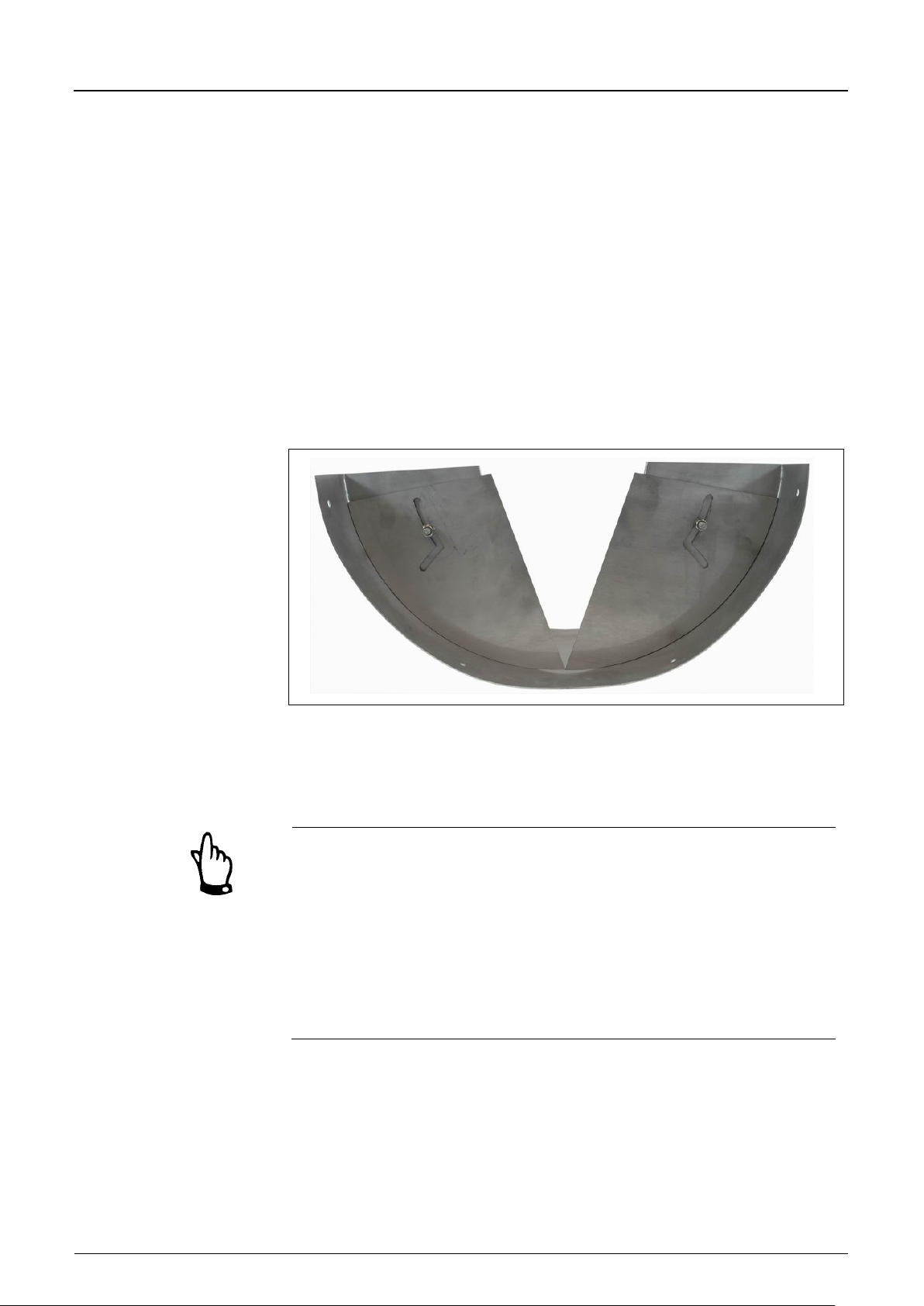
In case of very low flow levels and/or high flow velocities an adjustable so-called
dam-up element may create better flow conditions.
Functional principle:
The water is going to be dammed up in the area around the sensor by reducing
the cross-sectional area. Resulting in a higher fill level and a reduced flow
velocity this measure will optimise the flow behaviour.
The dam-up element is going to be installed approximately in the middle of the
channel between approach and discharge section. This does not reduce the
cross-sectional areas of the pipes. Larger amounts of water are able to flow over
the dam-up element.
These elements are available from NIVUS in various diameters. This special
backwater systems should preferably be installed by experienced and qualified
personnel however.
Fig. 6-14 Dam-up element
When uncertain regarding the choice or assessment of the planned
measurement distance, please contact your NIVUS representative or the
diversion Flow measurement technology at NIVUS GmbH in Eppingen.
Choosing the best possible measurement place and correct installation are
indispensable if temporary flow measurements are to be implemented! This
requires comprehensive knowledge on hydraulic situations and conditions.
Please note that improper, faulty or unsuitable installation as well as selecting
unsuitable or hydraulically problematic measurement places may lead to
faulty or incomplete measurement values which may be insufficient for further
processing and editing. This is why the installation should be carried out by
authorized personnel only.
Please contact NIVUS in order to perform according training measures.
Page 32
Instruction Manual
PCM F
PCM F - Rev. 00 as of 24.10.2007 Page 33
6.3.3 Sensor Installation
Wedge sensor
To temporarily fasten the wedge sensor on the channel bottom it is
recommended to use the pipe mounting system (Art.-Nr. PCM0 RMS2 0000
000). This system is designed to be used in channels with diameters from 200 to
800 mm (7.9 to 31.5 in) or egg profiles up to h = 600 mm. You can find a
description of the pipe mounting system in Chapter 6.3.4.
Fastening the sensor on the channel bottom permanently requires to use
4 stainless steel screws as well as appropriate dowels. The length of the screws
should be between 30 and 70 mm (1.18 and 2.76 in) depending on bearing
capacity and constitution of the ground. Make sure that the length of the screws
ensures safe and durable sensor fastening under all operational conditions.
To reduce the risk of eddy formation or build-up use precisely fitting countersunk screws and screw them completely into the ground plate.
NIVUS does not recommend to use stud bolts or similar for installation.
If not agreed otherwise with NIVUS install the sensor exactly in the channel
centre with the bevelled side looking towards the flow direction.
The sensor shape has been flow-optimised in order to reduce the risk of buildup. However there is a certain residual risk of build-up on the sensor ground
plate. This is why no gaps shall remain between sensor ground plate and
channel bottom!
The channel bottom must be exactly plane for sensor installation! Otherwise
the sensor may break and leak whilst tightening the screws.
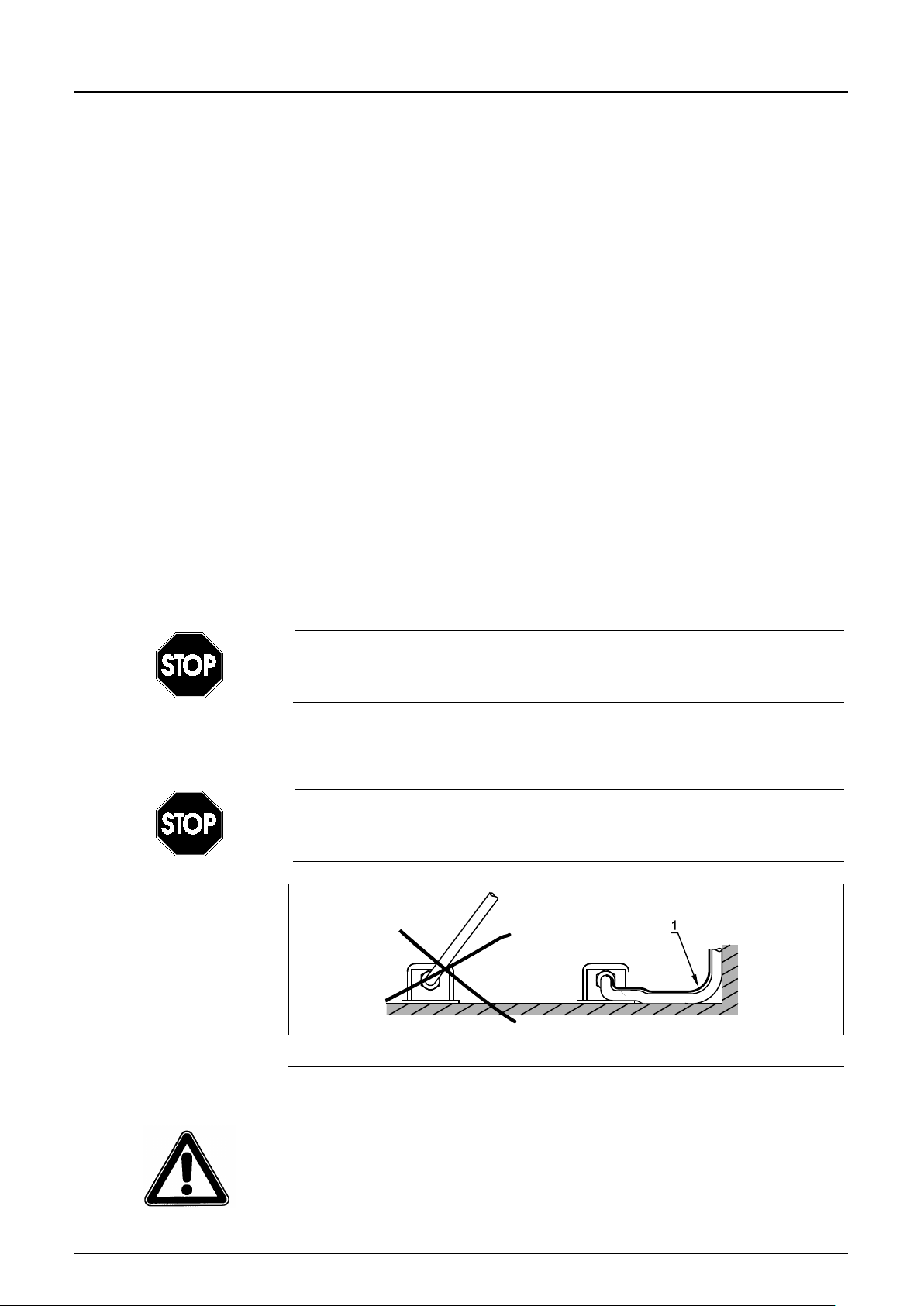
To avoid the risk of build-up the sensor cable shall be laid from behind the
sensor to the channel wall on the bottom of the channel.
Never lay the cable loosely, unprotected or across the medium! Risk of buildup, sensor or cable tear-off!
1 Protective cover
Fig. 6-15 Hints on cable layout
The minimum permissible bending radius of the signal cable is 10 cm (3.9 in).
A lower radius involves the risk of cable breaks!
Page 33
Instruction Manual
PCM F
Page 34 PCM F - Rev. 00 as of 24.10.2007
Never remove any parts from the sensor since this will invalidate warranty!.
Removing or loosening the senor from ground plate or cable gland lead to
leakage resulting in measurement or sensor failure.
To avoid disturbances caused by electric interferences never lay the sensor
cable close to engine (motor) lines, frequency converter lines or main power
lines.
Pipe sensor
The pipe sensor is going to be screwed tightly into the 1½ “ nozzle by using a
cutting ring screw and spigot nut (additional option: ball valve for removal without
pressure or retractable fitting to move the sensor back under operational
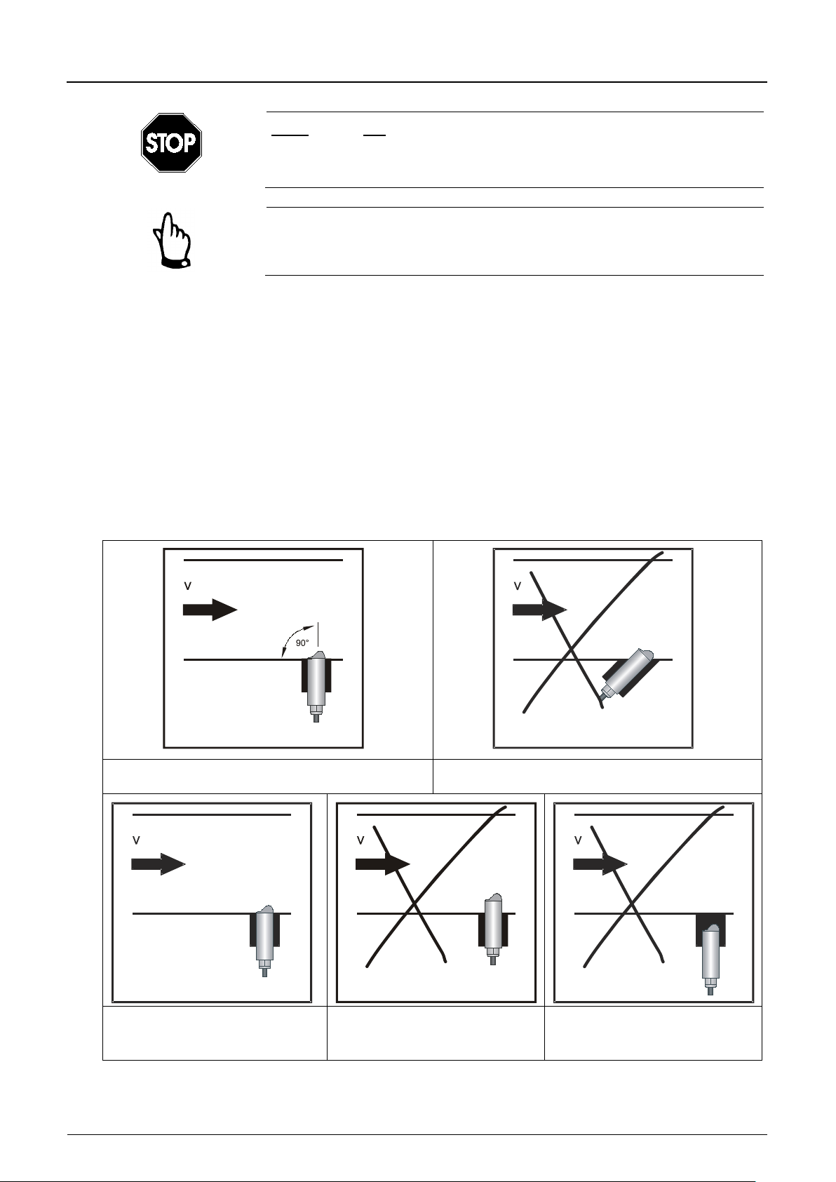
conditions). It is important that the horizontal part of the sensor is installed flush
with the pipe wall (Fig. 6-16, far left).
The cutting ring of the sensor will warp during installation and thus can be used
only once. If you should require new cutting rings please contact your NIVUS
representative.
Please note whilst installation in pipes:
weld on the 1½“ nozzle in an angle of 90°
Correct installation Error: distortion of values
Correct installation Error: risk of build-up Error: distortion of values or
measurement failure
Page 34
Instruction Manual
PCM F
PCM F - Rev. 00 as of 24.10.2007 Page 35
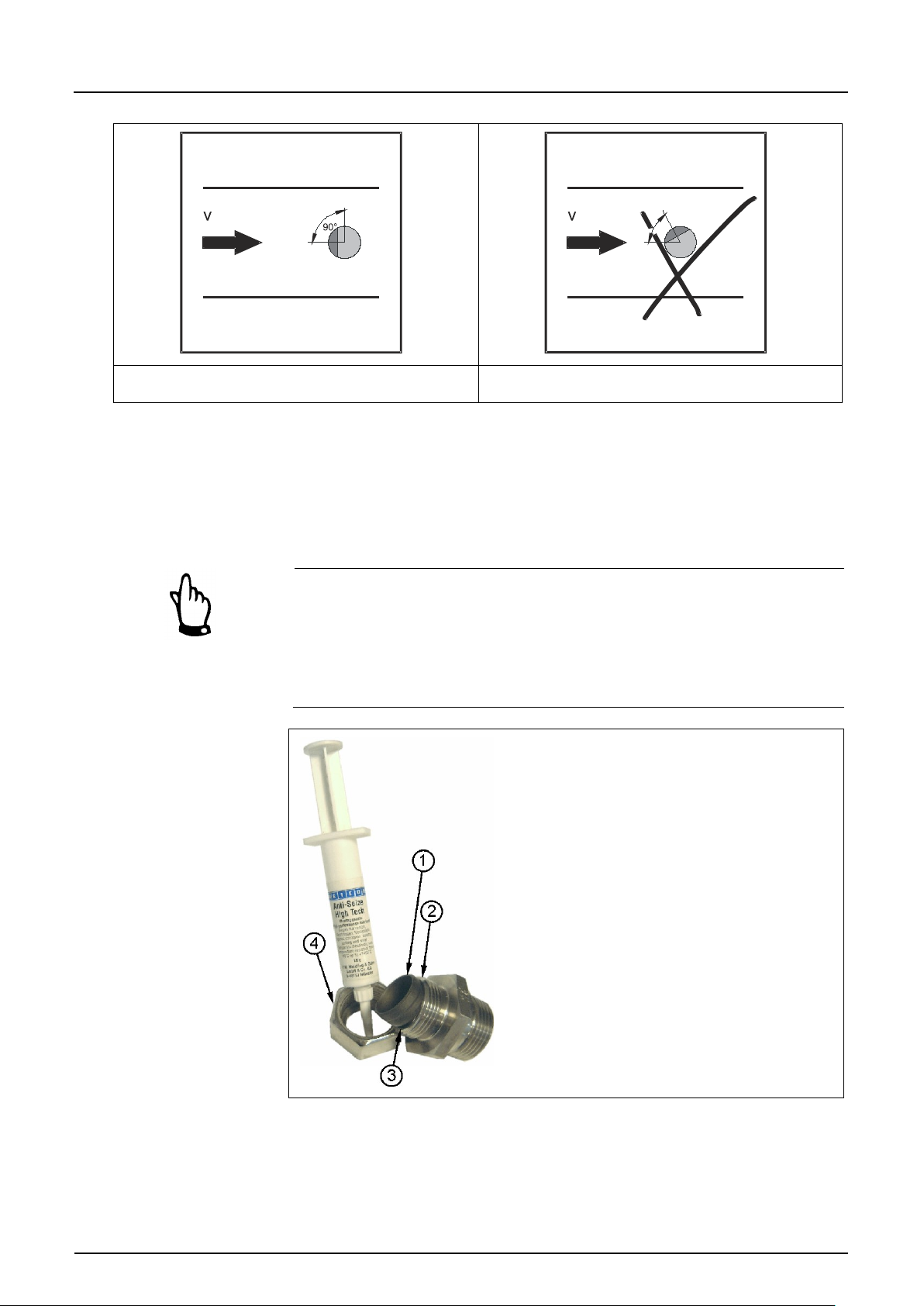
1 Cutting ring insi de and outside
Sensor face 90° towards flow direction Error: distortion of values
Fig. 6-16 Hints on pipe sen sor installation
Place the sensor in a way that the bevelled side is looking exactly towards the
flow direction. The screw which is located 180° to the flow direction (see
Fig. 6-4, Pos. 6) supports positioning.
When using a combi sensor with simultaneous ultrasonic level detection from
bottom up please observe absolutely horizontal installation (±2 °).
When assembling the insertion sensor, a special grease paste as specified in
DIN 2353 (or equivalent) must be used for stainless steel couplings.
The cap nut thread, threads and cone as well as the cutting ring must be
slightly greased when pre-assembling the insert ion sen s or!
The screw joints are greased on delivery. Additional grease can be purchased
from NIVUS or local dealers
2 Thread
3 Inner cone
4 Inner thread of spigot nut
Fig. 6-17 Using the grease
Page 35
Instruction Manual
Page 36 PCM F - Rev. 00 as of 24.10.2007
2 Ground plate 2
3 Ground plate 3
4 Cut-out for pipe mounting plate
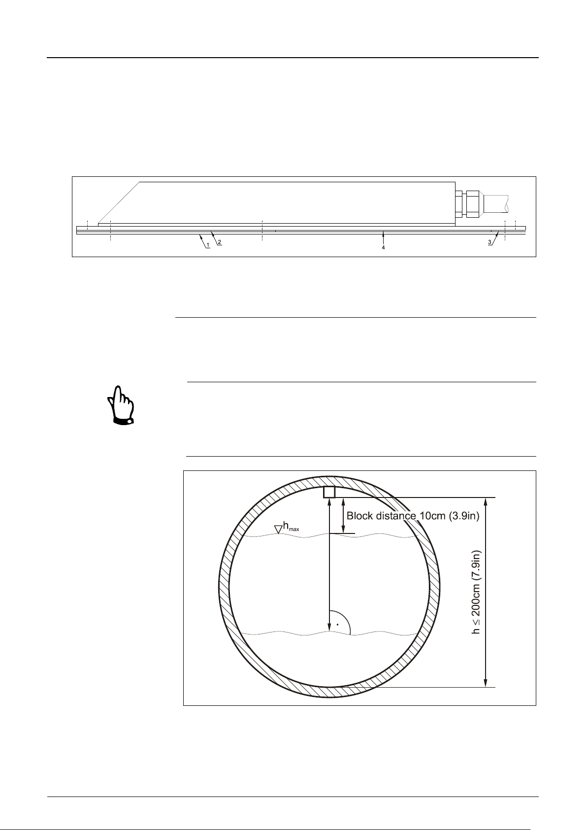
Air-ultrasonic sensors
On delivery the air-ultrasonic sensor Type OCL is designed for clamping
installation using a pipe mounting system Type RMS (Chap. 6.3.4).
For installation using the RMS the mounting sheet located in the pipe vertex
must be put through cut-out 4 of the air-ultrasonic sensor prior to complete
assembly (see Fig. 6-18)
1 Ground plate 1
Fig. 6-18 Air-ultrasonic sensor for fastening on pipe mounting system
PCM F
Before clamping the system into the pipe adjust the sensor exactly parallel to the
water surface.
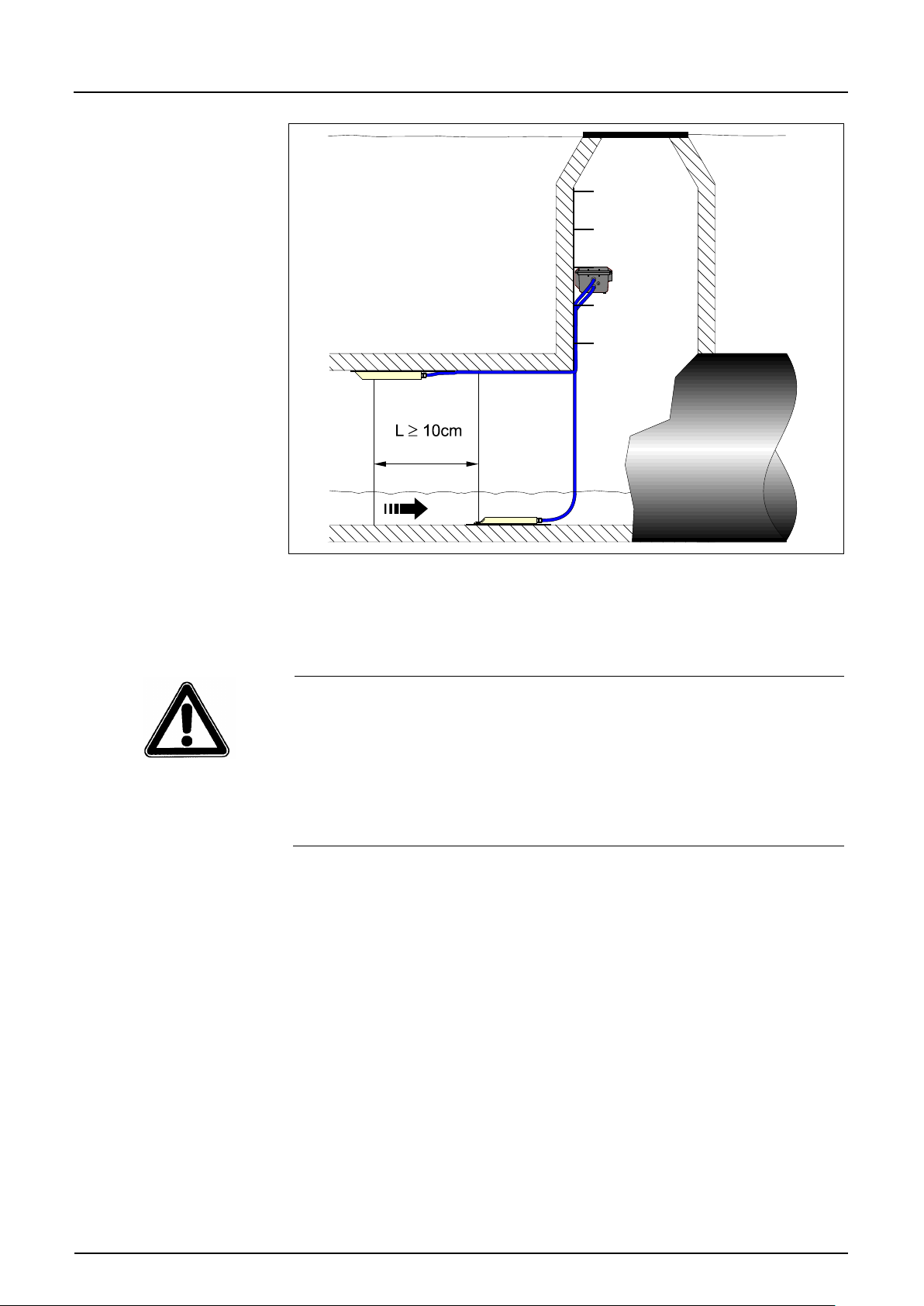
If the air-ultrasonic sensor is going to be installed together with the Doppler
sensor please observe to install the air-ultrasonic sensor at least 10 cm
(3.9 in) downstream of the Doppler sensor. This helps to avoid hydraulic
effects caused by the Doppler sensor (dam-up) to influence the ultrasonic
level measurement.
Fig. 6-19 Installation of air-ultrasonic sensor
Page 36
Instruction Manual
PCM F
PCM F - Rev. 00 as of 24.10.2007 Page 37
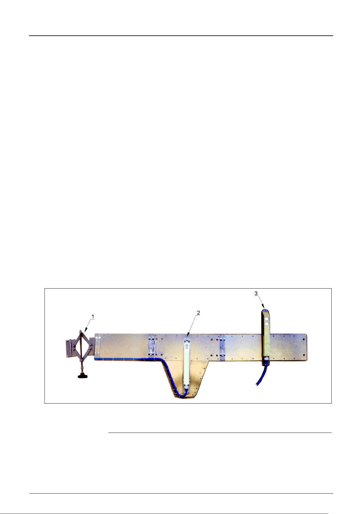
Fig. 6-20 Arrangin g th e sensors
For permanent installation the air-ultrasonic sensor can be fixed on the channel
vertex by using 3 appropriate stainless steel screws M5 and appropriate dowels.
The dead zone of the air-ultrasonic sensor Type OCL is 10 cm (3.9 in). Fill
levels within this dead zone cannot be measured.
Flooding the air-ultrasonic sensor will cause the sound to be coupled into the
measurement medium. Due to significantly higher sound velocities contrary to
air, this will result in the risk of faulty level measurement. This is why the flood
area of the air-ultrasonic sensor has to be avoided on programming. The airultrasonic sensor must NOT be activated within this range!
Page 37
Instruction Manual
Page 38 PCM F - Rev. 00 as of 24.10.2007
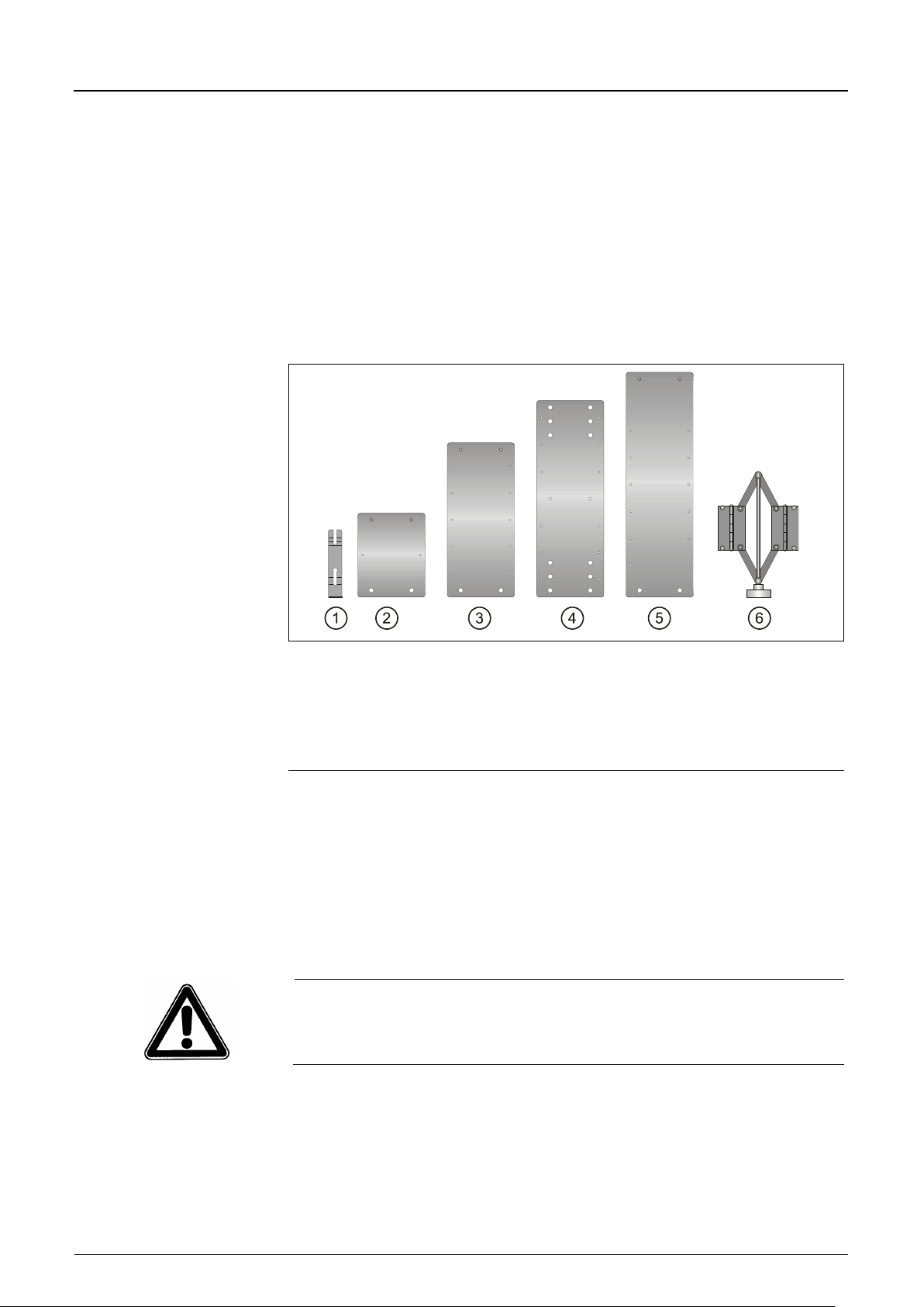
1 Fastening clip
2 Extension sheet V5
3 Extension sheet V10
4 Base plate
5 Extension sheet V15
6 Scissors jack
6.3.4 Pipe Mounting System
The pipe mounting system consists of the elements below
- scissors jack
- base plate
- fastening clips
- extension sheets (optional)
Select the required elements according to Fig. 6-21 and Fig. 6-26 and the
existing pipe diameter.
PCM F
Fig. 6-21 Components of the pipe mounting system
During assembly please observe to always locate the scissors jack at the pipe
vertex and the base plate on the channel bottom. Extension sheets which might
be required shall be put on the right-hand side and on the left-hand side
between scissors jack and base plate.
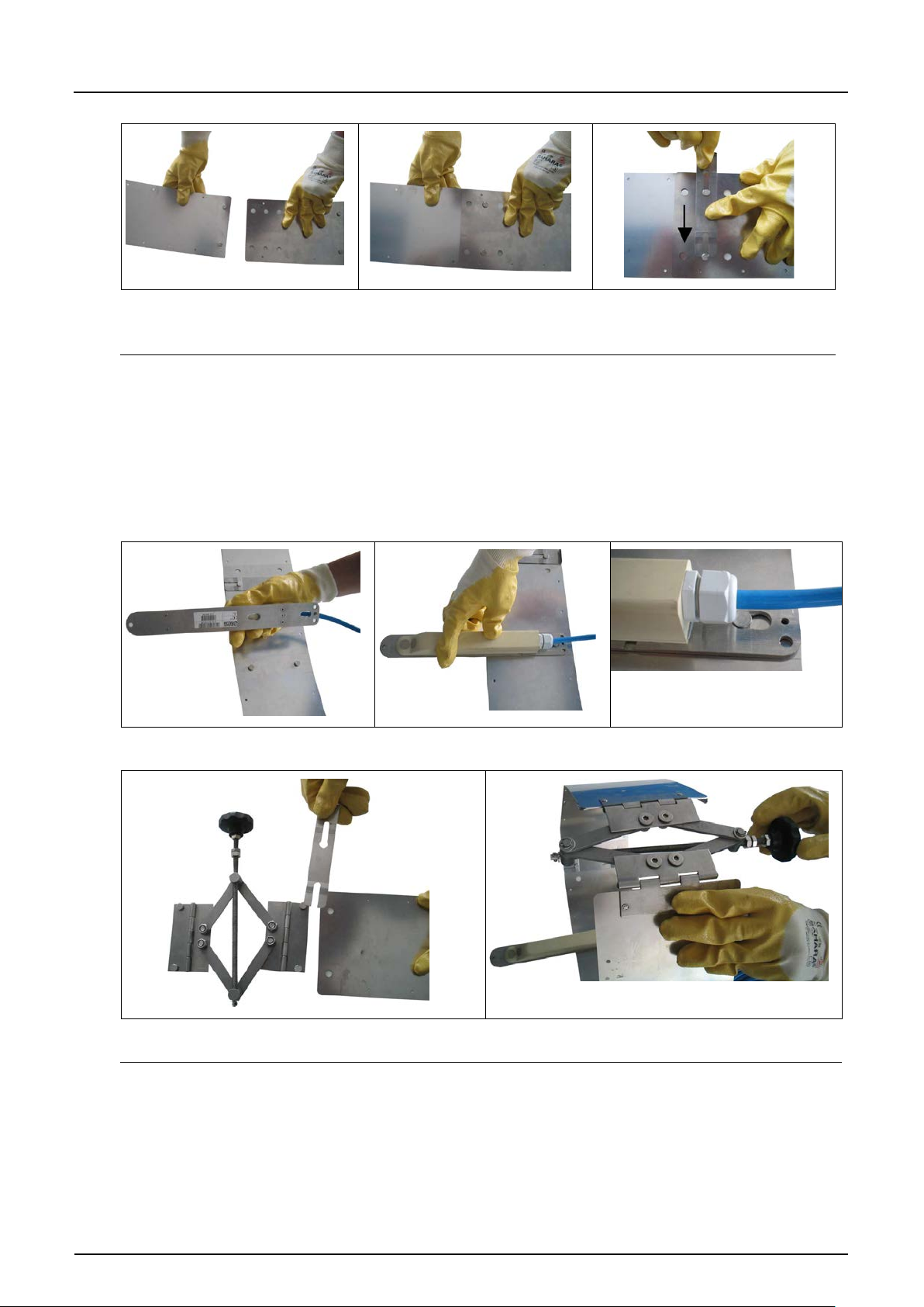
The fastening clips serve for quick installation. They must be put flush onto the
mounting plate against the flow direction (see Fig. 6-22; far right).
The plates are sharp-edged due to being made of light-gauge metal sheets.
Please always wear protective gloves to install or dismantle the pipe mounting
system!
Page 38
Instruction Manual
PCM F
PCM F - Rev. 00 as of 24.10.2007 Page 39
Assemble base plate and
Put the pins into the holes
Lock pins by using fastening clip
Put the sensor with the cut-outs
Push back...
... until it is locked (flush to
Fix the scissors jack on both sides of the final plate
Close the scissors completely by rotating the
extension sheet
Fig. 6-22 Installation with fastening clips
Snap the flow velocity sensor with the both slotted holes on the rear onto the
base plate (see Fig. 6-2).
Rotate the clamp handle of the scissors jack clockwise until the scissors are
closed. After that put the entire system into the pipe, adjust it and fix it in the pipe
by rotating the clamp handle counter-clockwise.
(must sit flush to mounting plate
against flow direction)
(slotted holes) onto the plate
by using the fastening clip
Fig. 6-23 Assembly of Pipe Mounting System
plate)
clamp handle before installing in the channel
Page 39
Instruction Manual
PCM F
Page 40 PCM F - Rev. 00 as of 24.10.2007
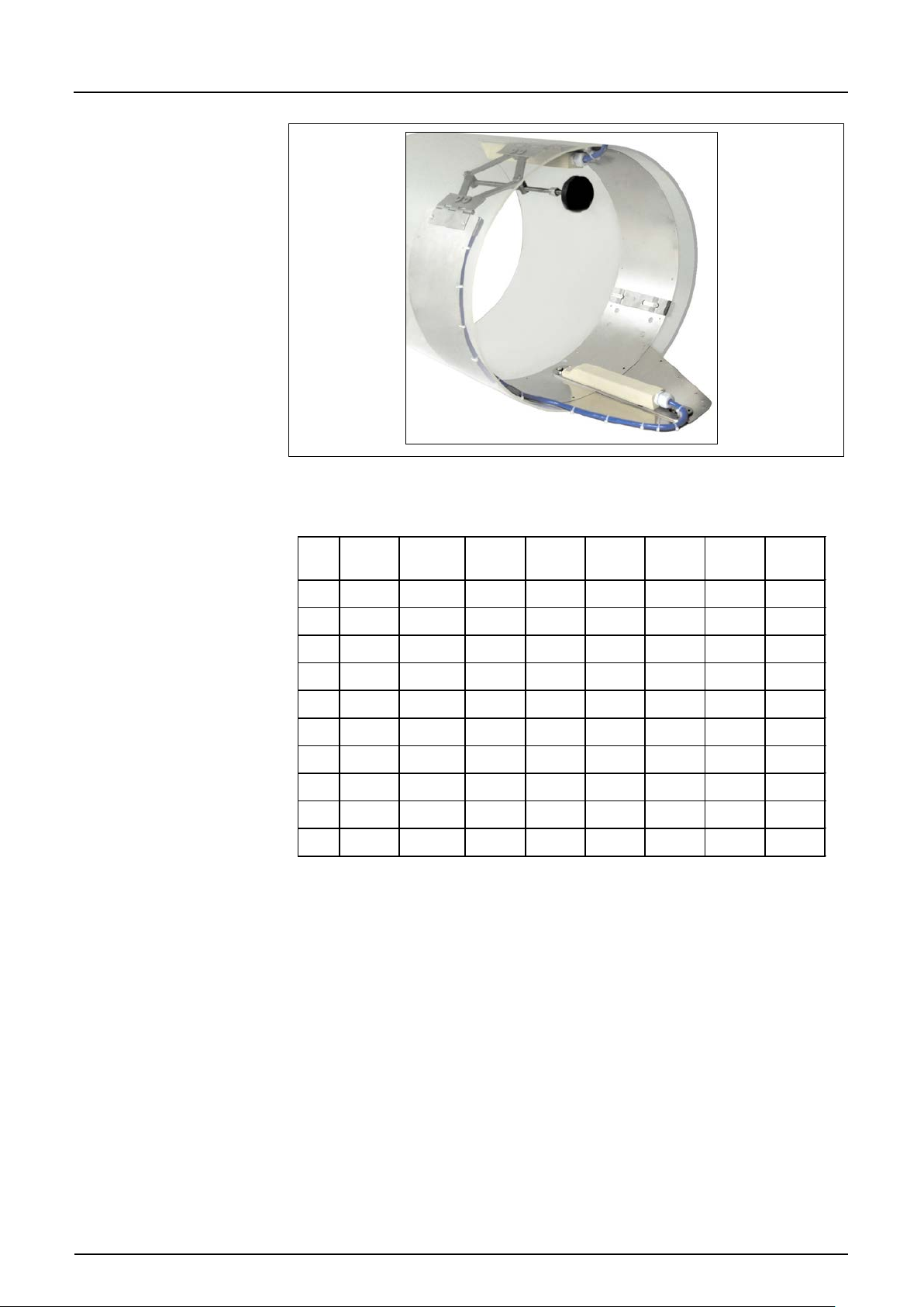
2 Wedge-shaped water-ultrasonic combi sensor
3 Air-ultrasonic sensor
Furthermore please observe the following regarding temporary installation by
using the pipe mounting system:
- Sufficient contact pressure to the channel wall in order to prevent the pipe
mounting system from getting loose. This is important especially in large
channel diameters and high flow levels.
If necessary the system must be secured additionally in order to protect it
from being washed away (e.g. by putting additional stainless steel screws
into the channel wall)
- Mount parallel to the channel wall to minimize the risk of build-up. No gap
between mounting plate and sensor or channel bottom may remain.
- The sensor cable shall be laid to the upside along the mounting system by
using cable fasteners.
- Always lay the sensor cable close along the channel wall and fix it with
clamps if necessary.
- Please refer to the list of mounting sheets (Fig. 6-26).
- If the active air-ultrasonic sensor and the Doppler sensor are used
simultaneously please use the support plate additionally (Art.-N r. PC P0
ZRMS 2Z00 000). Here the Doppler sensor is fastened on the base plate
with both the slotted holes on the sensor front (see Fig. 6-2). The support
plate serves to ensure proper cable layout as well as to correctly place the
Doppler sensor behind the air-ultrasonic sensor.
- The air-ultrasonic sensor is clamped to the extension plates by using its
double mounting plate. It shall be installed exactly plane parallel to the water
surface (see also Fig. 6-19)
1 Scissors jack
Fig. 6-24 Sensor fastening on pipe mounting system
Page 40
Instruction Manual
PCM F
PCM F - Rev. 00 as of 24.10.2007 Page 41
ø innen
in mm
BST
Basisstück
SPV
Spann-
vorrichtung
V5
Ver-
längerung
V5
Verl-
ängerung
V10
Ver-
längerung
V10
Ver-
längerung
V15
Ver-
längerung
V15
Ver-
längerung
200
X
Loch innen
X
250
X
Loch innen
X X X
300
X
Loch außen
X X X
350
X
Loch innen
X X X
400
X
Loch außen
X X X
450
X
Loch innen
X X X X X
500
X
Loch außen
X X X X X
600
X
Loch außen
X X X X X
700
X
Loch außen
X X X X X
800
X
Loch außen
X X X X X X X
Fig. 6-25 Pipe mountin g system with extension sheet for combined
installation of Doppler sensor and air-ultrasonic sensor
Fig. 6-26 List of mounting sheets
Page 41
Instruction Manual
Page 42 PCM F - Rev. 00 as of 24.10.2007
6.3.5 Sensor Connection
Doppler Sensor and Air-Ultrasonic Sensor
Doppler sensor as well as air-ultrasonic sensor are equipped with the
respectively wired plugs. These plugs must be connected to the transmitter
according to Fig. 6-1. To do this, unscrew the protective covers from the
required sockets, plug in and manually tighten the screw caps on the plugs in
order to ensure the grade of protection and secure contact.
Keep threads of plugs and sockets carefully free of dirt, sand or similar and
clean the threads with a soft and lint-free cloth prior to connection if required
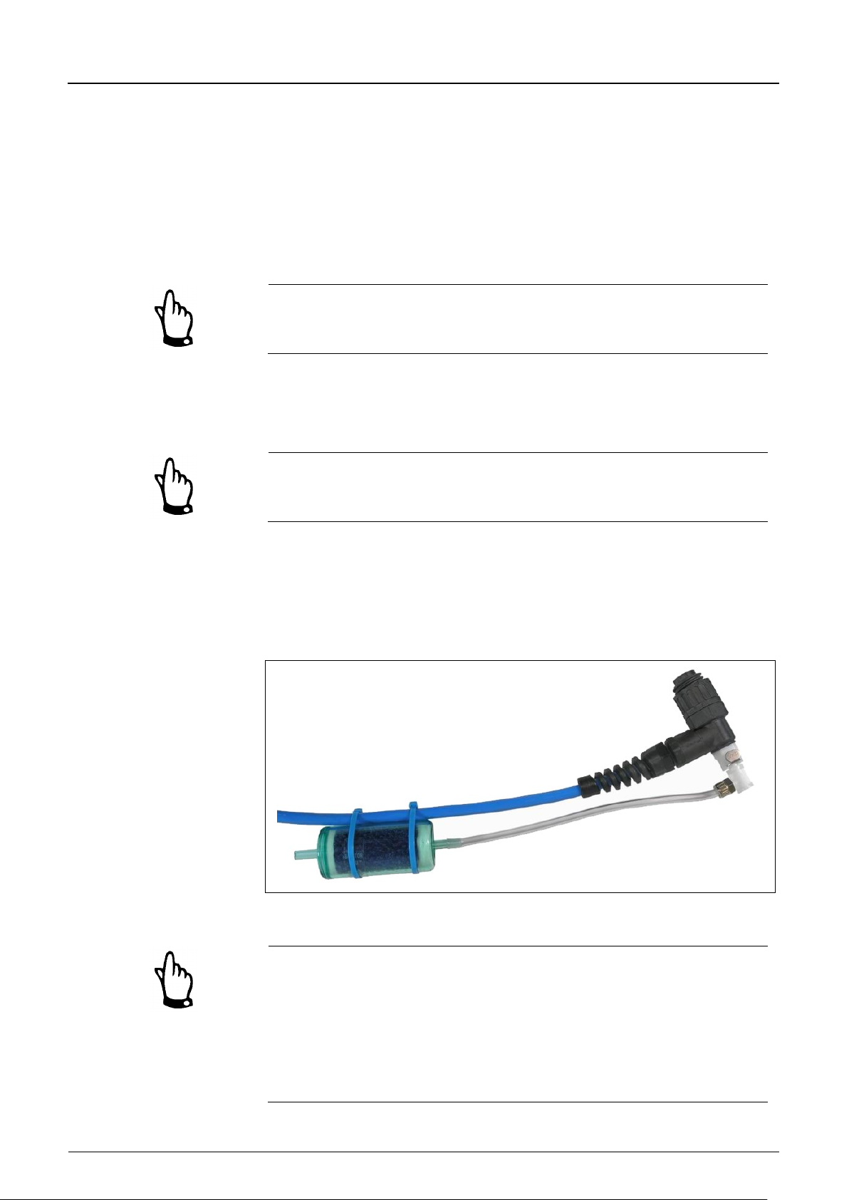
Sensors with an integrated press ur e cell are equipp ed with an add iti ona l air filt er
with a dehydration agent on the connection plug. This air filter is necessary to
constantly adjust the pressure cell according to the current air pressure.
If the colour indicator contained within the dehydration agent turns from blue
to pink the filter must be replaced immediately.
PCM F
Spare filters with plug and connection hose are available from NIVUS under Art.No. POA0ZUBFIL00000.
If there is a risk of flooding the filter please ensure to correctly install the air
hose. This means that the air hose must be installed without sharp bends above
the possible maximum water level.
Fig. 6-27 Connection pl u g with air filter
Sockets on the PCM F which are not required for measurements, sensors or
data transmission must be locked watertight before installation by using the
covers fastened on each socket. Otherwise the protection grade of the entire
unit is no longer guaranteed. Damages resulting from missing covers are not
covered by the manufacturer’s liability.
If covers may get lost caused by the use of force, they can be ordered from
NIVUS at extra cost.
Page 42
Instruction Manual
PCM F
PCM F - Rev. 00 as of 24.10.2007 Page 43
Art.-No.
Wire colour
Function
Pin assignment
ZUB0KABNMCxxS0
brown
16 V (+)
3
When using sensors with integrated pressure cell and air filter the complete
measurement system must never be operated without the filter!
If the filter plug is removed from the sensor plug it will be locked
automatically. This prevents water from getting into the sensor, but air
balance is impossible too. It is no longer possible to accurately measure the
filling level by using the pressure cell then.
The air balance hose must neither be hanging in the water nor be blocked or
have sharp bends. Please ensure cont in uous and unh ind er ed air flow int o the
filter.
External level sensors
External 4-20 mA 2-wire sensors (such as compact echo sounder Type
NivuCompact, hydrostatic level measurement Type NivuBar Plus, ...) can be
connected to the PCM F for level measurement. The supply voltage for the
sensors is 16 V. Connect the sensors to PCM F via socket 3.
There are pre-configured cables with various lengths available:
(PCM F –> 2-wire 4 -20 mA sensor)
white
4 – 20 mA (-)
on plug
4
Page 43
Instruction Manual
Page 44 PCM F - Rev. 00 as of 24.10.2007
Art.-No.
Description
PC40 ZVER AE
Connection cable, PCM F – analog input (one side with
PC40 ZVER AA
Connection cable, PCM F – analog output (one side with
PC40 ZVER DE
Connection cable, PCM F – digital input (one side with
PC40 ZVER RA
Connection cable, PCM F – relay output (one side with
Art.-No.
Wire colour
Function
Pin assignment
PC40 ZVER AE
grey
0/4 – 20 mA
3 2 PC40 ZVER AA
pink
0 – 10 V
4 5 PC40 ZVER DE
white
DE active 3.3 V
6
PC40 ZVER RA
green
root contact (COM)
8
6.3.6 Peripheral Equipment Connection
The PCM F is equipped with various analog and digital inputs and outputs which
enable to connect a variety of sensors or actuators. An according overview can
be found in Fig. 2-2.
Individual connections can be connected directly to the multifunctional socket
(see Fig. 6-1) by using pre-configured cables. The following cable types are
available:
plug for multifunctional socket, other side with open
cable end); length of cable 10 m (32.8 ft)
plug for multifunctional socket, other side with open
cable end); length of cable 10 m (32.8 ft)
plug for multifunctional socket, other side with open
cable end); length of cable 10m (32.8 ft)
PCM F
Wiring of pre-configured Cables
(PCM F –> analog input)
(PCM F –> analog output)
(PCM F –> digital input)
(PCM F –> relay output)
brown
brown
brown
brown
grey
plug for multifunctional socket, other side with open
cable end); length of cable 10m (32.8 ft)
on plug
AGND
GND
GND
normally closed (NC)
normally open (NO)
5
7
1
Page 44
Instruction Manual
PCM F
PCM F - Rev. 00 as of 24.10.2007 Page 45
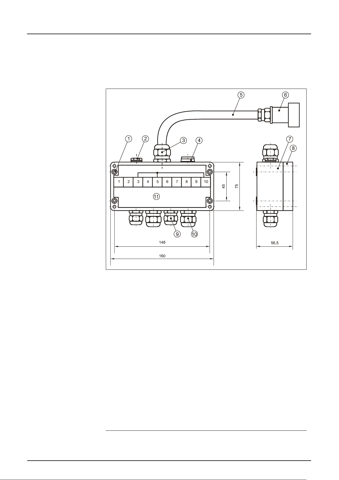
2 Pressure compensation element DAE7
3 M20x1.5 cable gland HSK-K
4 Dummy plug M16x1.5
5 Connection cable 1m (3.28 ft)
6 Multifunctional plug with 9 pins for connection to PCM F
7 Enclosure bottom
8 Enclosure lid
9 M16x1.5 (2x) cable glands / peripheral side
10 M20x1.5 (2x) cable glands / peripheral side
11 Terminal clamp compartment /
1 Analog input (0 - 20mA) passive
6.3.7 Connector-Box
In order to simultaneously connect several signals there is a Connec tor -Box
available. This item can be purchased from NIVUS using order code No.
PC40ZVS10000000.
1 Drilled holes for screws M4 for enclosure fastening
wiring
2 Analog ground (AGND)
3 GND
4 Analog output (0 - 10V)
5 GND
6 Digital input
7 Relay output (NC)
8 Relay output (COM)
9 Relay output (NO)
10 Shield
Fig. 6-28 Overview Connector-Box
Page 45
Instruction Manual
Page 46 PCM F - Rev. 00 as of 24.10.2007
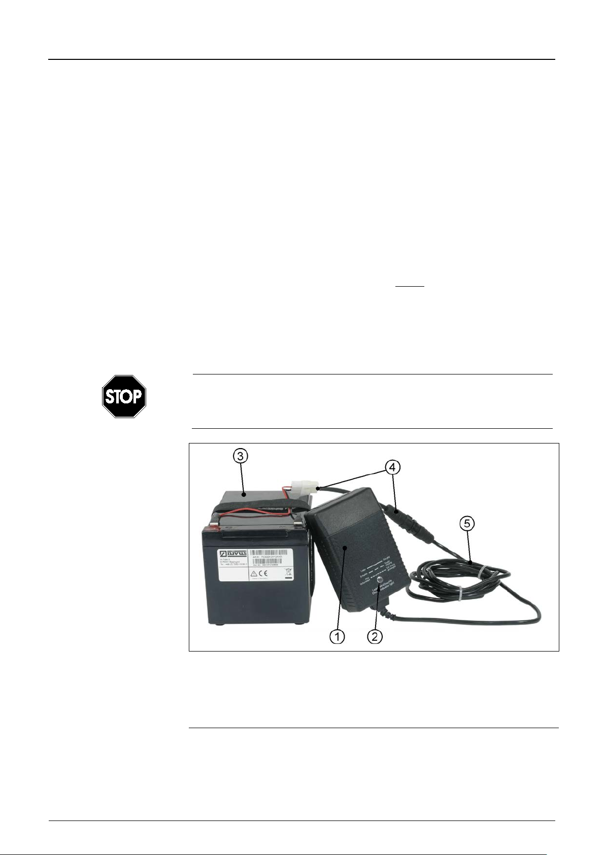
2 LED indicator
3 Rechargeable lead gel battery
4 Adapter
5 Connection cable
6.4 PCM F Power Supply
6.4.1 (Rechargeable) Batteries
A lead gel battery is part of the PCM F standard equipment. This battery pack
ensures long measurement periods.
Optionally it is possible to use standard batteries in conjunction with a battery
box (Art.-No. PC40ZBBOX000000). The quality of the standard batteries is
essential for the duration of the measurement period! Use only batteries from
renowned manufacturers therefore.
The rechargeable battery pack is located in a padded battery compartment. This
compartment is locked with a lid and 4 knurled screws.
The rechargeable battery will be delivered in charged condition. Due to reasons
of operational safety it is required to reload it before the first use.
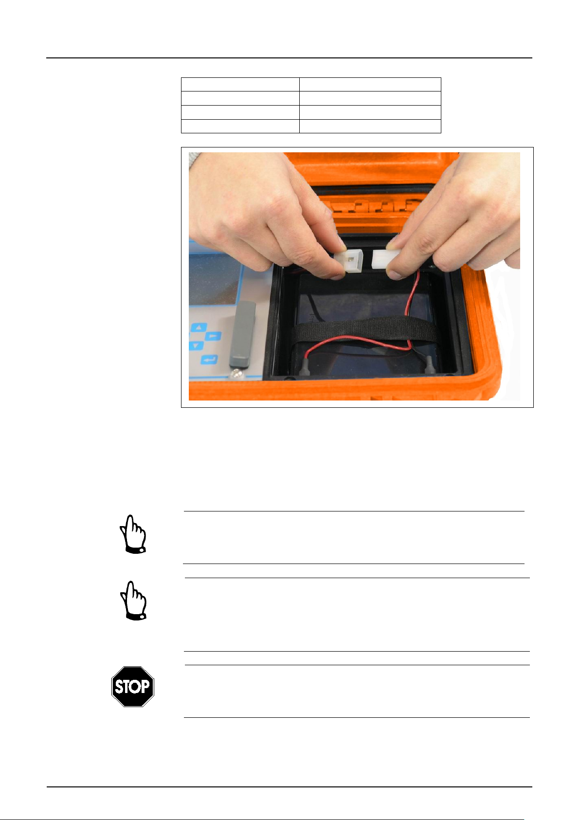
In order to charge or to replace the battery pack unscrew the 4 screws of the
battery compartment lid and remove the cover. Unplug the plug connection and
remove the battery pack.
Subsequently tighten the knurled screws (see Fig. 2-1) of the compartment lid
manually.
PCM F
To charge the battery use the NIVUS battery charger exclusively. Please
observe the specifications of the battery charger.
Charge the battery in dry environments only.
1 Battery charger
Fig. 6-29 Battery charger with rechargeable battery pack
Always disconnect battery charger/power adapter from mains prior to connecting
to or disconnecting from the rechargeable battery. The built-in LED indic at es the
charging status.
Page 46
Instruction Manual
PCM F
PCM F - Rev. 00 as of 24.10.2007 Page 47
LED colour
Status
yellow
charging battery
green
trickle charging
LED not lit
reversed polarity or short circuit
Fig. 6-30 Plug connection to rechargeable battery
The maximum capacity of the rechargeable battery is going to deteriorate in the
course of time. This will reduce the lifetime which cannot be considered by the
integrated lifetime calculation function of the PCM F.
High or low ambient temperatures and long periods of use are going to reduce
the battery capacity as well.
Rechargeable batteries are subject to wear and tear and shall be replaced
after a maximum of two years.
This period may be shorter if being used extensively.
The rechargeable battery should be charged each time before using the
PCM F.
Remove unused batteries after the latest measurement, store them in a dry
and frost-free place and recharge them after 2 months in order to maintain
capacity as long as possible
The use of spare / replacement parts (such as rechargeable batteries or
similar) not authorised by NIVUS will invalidate liability claims.
Always keep the battery compartment firmly locked during operation.
Please make sure to dispose of rechargeable batteries or standard batteries
according to laws on environments.
Used batteries can be returned to the manufacturer.
Page 47
Instruction Manual
Page 48 PCM F - Rev. 00 as of 24.10.2007
6.4.2 Mains Connection
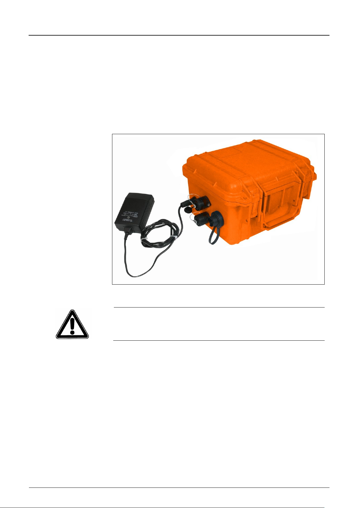
It is possible to power the PCM F directly from mains (100 - 240 V AC) b y usin g
the combined mains adapter / battery charger. To do this connect the plug of the
mains adapter / battery charger to the according PCM F socket (see also
Fig. 6-1). The rechargeable lead gel battery shall remain in the PCM F during
mains operation as it is going to be charged simultaneously. This ensures to
have it available as buffer battery in case of mains failures (charging process
begins as described in Chapter 6.4.1. The PCM F is ready for operation during
the charging process).
PCM F
Fig. 6-31 Battery charger directly connected to PCM F
Please observe the degree of protection of the mains adapter / battery
charger.
6.4.3 Alternative Power Supply
It is possible to additionally power the PCM F using alternative power sources
(such as solar panels) via the charger socket. For that purpose NIVUS
additionally provides an external battery box (PC40ZBBOXEXT) including a
rechargeable battery with 26 Ah. The voltage input operates from 11,5 to 30 V
and is protected against overvoltage, overcurrent and reversed polarity. All fuses
use an "Auto Reset“ function after errors have been removed.
Page 48

Instruction Manual
PCM F
PCM F - Rev. 00 as of 24.10.2007 Page 49
7 Initial Start-Up
7.1 General
Notes to the user
Before connecting and operating the PCM F please follow the notes below!
This instruction manual contains all necessary information to program and to
operate the device, addressing qualified technical staff who have appropriate
knowledge about measurement technology, automation technology, information
technology and waste water hydraul ics .
To ensure a correct function of the PCM F please read this instruction manual
thoroughly!
If any problems regarding installation, connection or programming should occur
please contact our technical division or our service centre.
General principles
It is not allowed to perform an initial start-up before the installation has been
finished and inspected. This manual shall be read prior to initial start-up in order
to eliminate the possibility of faulty programming.
Please get familiar with the PCM F programming via display and keyboard by
reading the instruction manual before you begin to program the device.
After transmitter and sensors have been connected (see chapters 6.2 and 6.3)
the measurement place parameters must be set. In most cases it is sufficient to
set:
- shape or geometry of the measurement place
- the sensor type for level / height measurement
- the memory mode
- the system clock (time and date)
The PCM F user surface is designed in a way that even unfamiliar users are
able to easily set up basic settings in graphic dialog mode which ensure reliable
device operation.
For extensive programming, difficult hydraulic conditions, special channel
shapes, in case of absence of expert staff or if a setup and error protocol is
required, the programming should be carried out by the manufacturer or an
expert company which is authorised by the manufacturer.
Page 49
Instruction Manual
Page 50 PCM F - Rev. 00 as of 24.10.2007
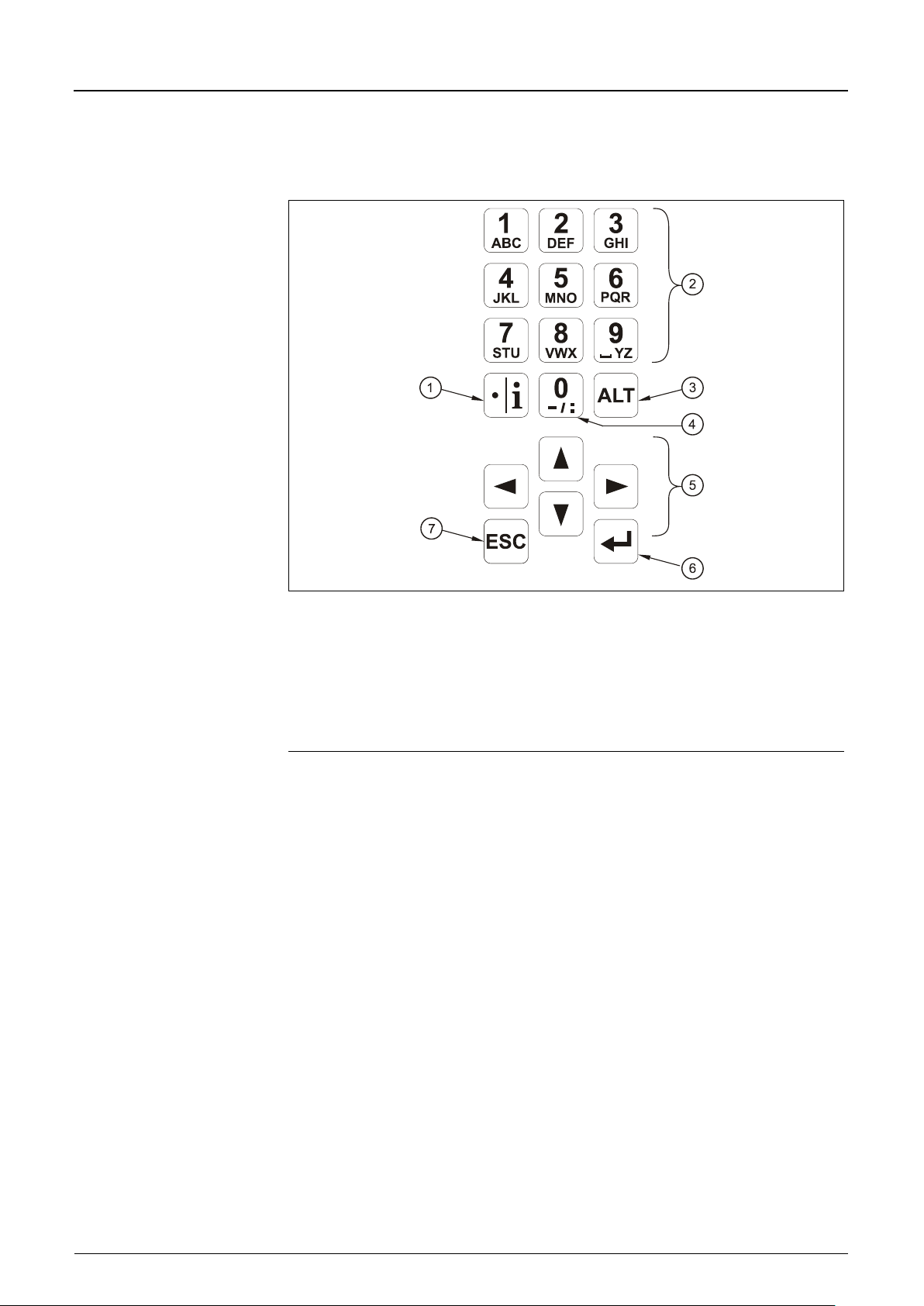
2 Number / letter keys
3 Shift key
4 0 / - navigation key
5 Arrow keys
6 Confirm key (ENTER)
7 Escape key
7.2 Keypad
PCM F
For data input there is a comfortable 18-button keypad available.
1 Decimal digit / info key
Fig. 7-1 Keypad
Page 50
Instruction Manual
PCM F
PCM F - Rev. 00 as of 24.10.2007 Page 51
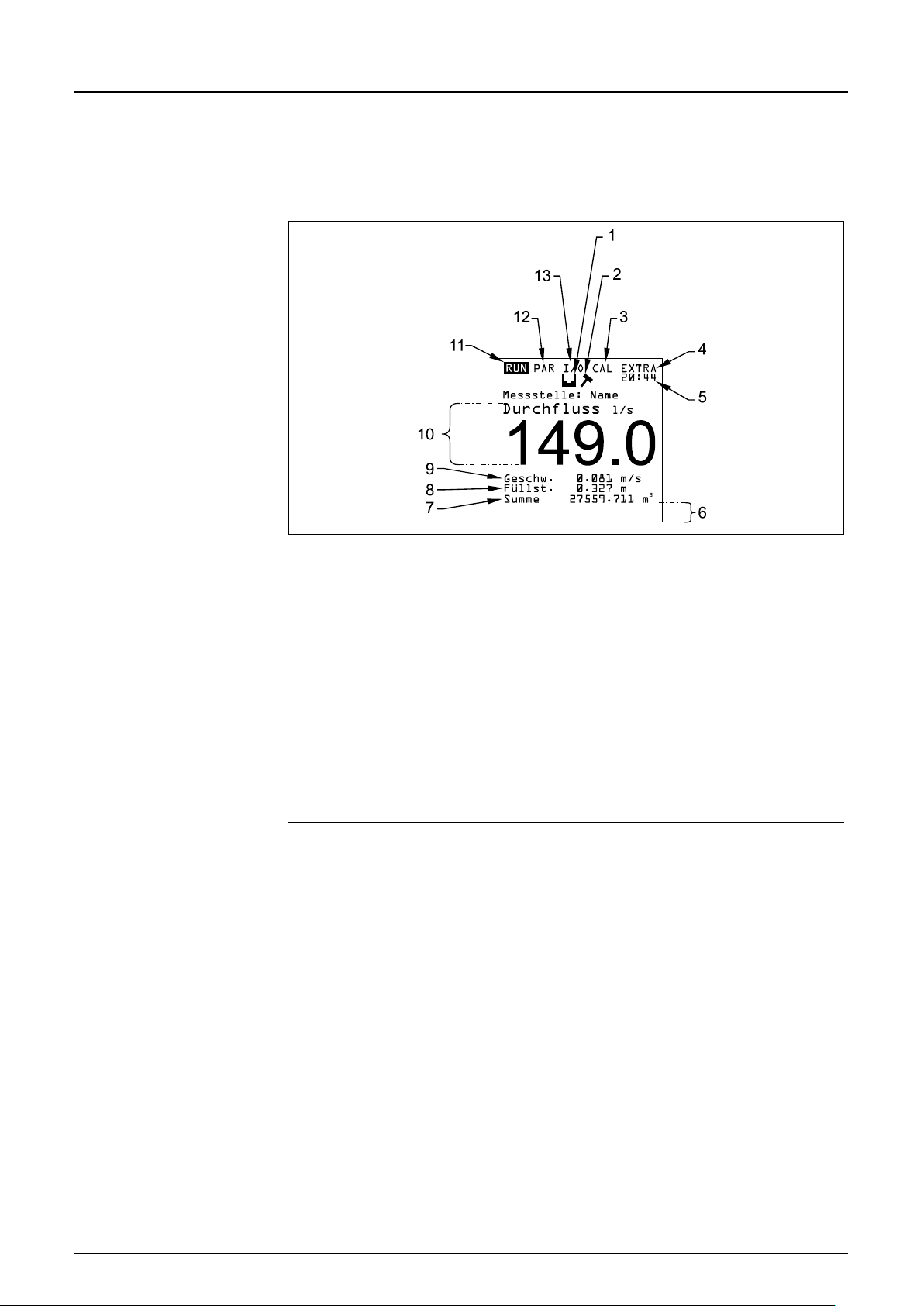
2 Service mode enabled
3 Calibration menu
4 Display menu
5 current system clock time, alternately appearing medium temperature
6 Field for indication of digital outputs
7 Total
8 Fill level reading (height)
9 Velocity reading
10 Flow reading
11 Operation menu
12 Parameter menu
13 Status menu of inputs, outputs and sensors
7.3 Display
The PCM F has a large back-lit graphic display with a resolution of 128 x 128
pixel. This ensures a comfortable communication mode for the user.
1 Memory mode enabled
Fig. 7-2 Display overview
Page 51

Instruction Manual
PCM F
Page 52 PCM F - Rev. 00 as of 24.10.2007
RUN
The standard operation mode. Apart from indicating the names of
PAR
This menu is the most extensive of the PCM F. It is for the complete
I/O
This menu includes information about internal operation of the
CAL
Here it is possible to adjust the level measurements as well as to
EXTRA
This menu contains basic display settings: contrast, lighting,
Five basic menus can be selected, visible in the headline of the display. They
can be selected individually. The menus are:
measurement places it allows to display time, flow volume, flow
level, flow velocity as well as to optionally show flow velocity
distribution using a histogram, day totals, error messages including
a function enabling to indicate trends regarding flow volume, flow
level and flow velocity.
setting of parameters regarding dimensions of the measurement
place, sensors, memory mode and includes other settings such as
the capacity of the rechargeable battery and more.
PCM F. Current readings can be recalled from here. By using
various submenus it furthermore allows to watch echo images from
sensors, evaluated individual velocities and more in order to asses
hydraulic conditions prevailing on the measurement place or to
determine the remaining capacities of memory card and
rechargeable battery.
modify settings regarding the automatic self-calculation of flow
volumes.
language, units, system times and totaliser presets.
Page 52
Instruction Manual
PCM F
PCM F - Rev. 00 as of 24.10.2007 Page 53
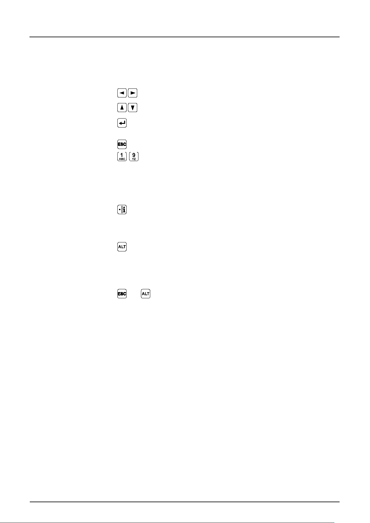
Use these buttons to select the main menus.
Buttons for scrolling within the menus.
Selected submenus can be entered, inputs can be opened. The
Exit submenus step by step. Rejects entered data.
-
These buttons are used for parameter setting and to enter digits.
The key “dot/i“ serves to input digits. In RUN-Mode it also recalls
This button is to toggle between uppercase and lowercase letters
Pressing >ESC< and >ALT< in quick succession will cause the
7.4 Operation Basics
The entire operation is menu driven and supported by explanatory graphics. To
navigate within the menu structure use the 4 control keys (see Fig. 7-1).
“Enter“ key further serves to confirm data entries.
In some sub menus the buttons are to input letters (e.g. name of
measuring point). Function compares with mobile phone or cell
phone buttons: quickly pressing a button more than once will
switch over to the next letter. The cursor will jump to the next digit
if no key will be pressed for approx. 2 seconds.
internal information on softwar e vers ions and us ed el e c tronic
components. The key furthermore serves to start communication
between transmitter and sensors.
in text entry mode. In the rest of the parameter setting mode it
serves to enable / disable various functions and hence is a toggle
key between different programming options. If used in RUN mode
the key is going to trigger a forced data dump to CF card.
unit to fall to sleep mode, disabling measurement as well as data
storage! The unit will be re-activated 7 seconds after any key has
been pressed.
Page 53

Instruction Manual
Page 54 PCM F - Rev. 00 as of 24.10.2007
7.5 Measurement and Display Functions
After the program settings have been finished the PCM F will restart performing
a complete system reset. The unit subsequently begins to measure using the
cycle set. The required measurement duration is going to be determined by the
PCM F within each cycle depending on flow and hydraulic conditions.
The number of storage events per hour will be calculated from a full hour divided
by the periodic interval. The reference to calculate the points in time is a full
hour.
Example:
- cycle set: 5 minutes
- programming finished: 12:17 h
- first storage: 12:20 h
- second storage: 12:25 h
- third storage: 12:30 h
and so on.
7.5.1 Display Functions in Memory Mode
PCM F
Case 1
The unit has been turned on for maintenance purposes (indication of data,
sensor check, battery replacement or similar) without modifying any parameters.
- The device shows the current readings for 3 minutes. Data will be saved in
the background according to the current cycle if the interval is set to less
than 3 minutes.
3 minutes after the last key action the unit falls to standby mode and the
display goes off. The display subsequently will activate for three times
following the cycle set. Due to energy-saving purposes the display now will
not re-activate again and the PCM F is going to proceed in the background
following the interval set.
Case 2
The PCM F has been re-programmed or parameters have been modified. After
that the modification has been confirmed by entering the PIN code.
- The display goes off for a moment, the PCM F is going to restart and
subsequently will indicate the current readings for 3 minutes. Data will be
saved in the background according to the current cycle if the interval is set to
less than 3 minutes
3 minutes after the last key action the unit falls to standby mode and the
display goes off. The display then will activate for five times following the
cycle set. Due to energy-saving purposes the display now will not re-activate
again and the PCM F is going to proceed in the background following the
interval set (see Fig. 7-3).
Page 54
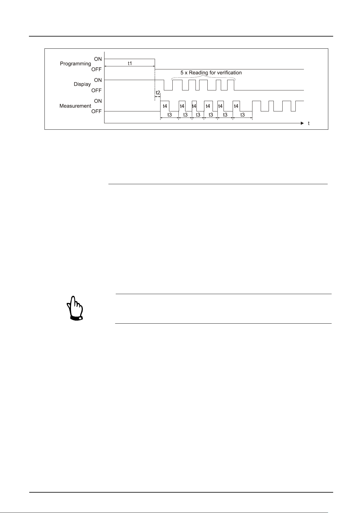
Instruction Manual
PCM F
PCM F - Rev. 00 as of 24.10.2007 Page 55
t1 = Programming time (any period)
t2 = System reset and restart (approx. 7 sec.)
t3 = Cycle time (constant, will change only in case of prog. event;
1 min. ... 60 min.)
t4 = Measurement time, depends on hydraulic und physical conditions,
will self-adjust automatically each time (5 sec. ... 40 sec.)
Fig. 7-3 Measurement and display functions after parameter
modification
7.5.2 Display Functions without Memory Mode
For initial set-up of the portable flow measurement system in difficult
applications, if using the unit for short-term and punctual verification of other
metering systems (flumes, weirs, magnetic-inductive systems or similar) or
throttles the memory function may be irrelevant. On the other hand it might be
important to permanently indicate current readings. The PCM F exactly meets
the requirements described before since the PCM F operates continuously as
long as the memory function is disabled.
Current readings are going to be indicated permanently on the display but will
not be saved however if the PCM F memory mode has not been enabled. At
the same time the power consumption will increase significantly.
Page 55

Instruction Manual
Page 56 PCM F - Rev. 00 as of 24.10.2007
8 Parameter Setting
8.1 Parameter Setting Quick Guide
In case of standard applications (such as part filled standard channel; level and
flow velocity measurement by combi sensor from bottom up, level measurement
using pressure, no values above or below minimum and maximum detectable fill
level of combi sensor, no vertical sensor offset) normally just a few basic
settings such as the ones below need to be set:
1. Install and connect transmitter and sensor as described in chapter 6
2. Connect power supply (charged battery)
3. Menu: PAR – Settings – execute system reset
4. Menu: I/O – System - Batt. full – confirm with >yes<
5. Menu: EXTRA – Units: select units for flow rate (l/s), velocity (m/s), fill level
[m] and total [m³] (units in brackets = default settings)
6. Menu: PAR – Measurement place – Channel profile: select profile
PCM F
7. Menu: PAR – Measurement place – Channel dimensions: enter channel
dimensions
8. Menu: PAR – Fill le ve l – Sensor type: select sensor type
9. Menu: PAR – Memory mode – Operation mode: select periodic, set interval
and define the units to be saved (flow [l/s], velocity [m/s], level [m] and total
[m³] (units in brackets = default settings))
Additional Setting Options
- Menu: EXTRA – System clock: adjust time if required (important for
synchronised operation of several PCM F units!)
- Menu: PAR – Measurement place – Name: enter the desired name of the
measurement place (default: NIVUS)
- Exit parameter mode. Save settings by entering >2718<. Calibrate the level
sensor if required.
Page 56
Instruction Manual
PCM F
PCM F - Rev. 00 as of 24.10.2007 Page 57
2718
Type in this number if prompted.
8.2 Parameter Setting Basics
The degree of protection of the unit (see chapter 2.3.1) can be guaranteed only
if the enclosure lid is closed and has been safely locked by using both locks.
Due to this reason always ensure to safely lock the transmitter before you begin
data logging, after settings have been finished and first readings have been
checked (see chapter 7.5).
In case of unfavourable situations regarding weather conditions (precipitation)
or locations with water leaking from above it is necessary to replace /
exchange batteries and / or CF card in a dry place.
If this should not be possible, sufficiently protect the opened unit from ingress
of moisture.
The unit shall be locked safely by using both snap locks after the parameters
have been set. Otherwise the protection degree cannot be guaranteed.
In parameter setting mode the unit will proceed to operate in the background
using the settings which have been previously saved. Just after you finish the
new entries, the system asks to accepting the new values.
“YES“ requires to enter the PIN code.
Never give the code number to any unauthorised persons. Even do not leave
the code next to the equipment or write it down on it. The code number
protects against unauthorized access.
If a faulty code has been entered three times the parameter mode will be
aborted. The unit will proceed to operate using the values set earlier. If the
correct code has been entered the modified parameters are accepted and the
system resets. This reset will take approx. 20-30 seconds.
After mounting and installing sensor and transmitter (see previous chapters)
activate the power supply. To do this connect the plug in the battery
compartment to the socket of the rechargeable battery (see Fig. 6-30).
Page 57
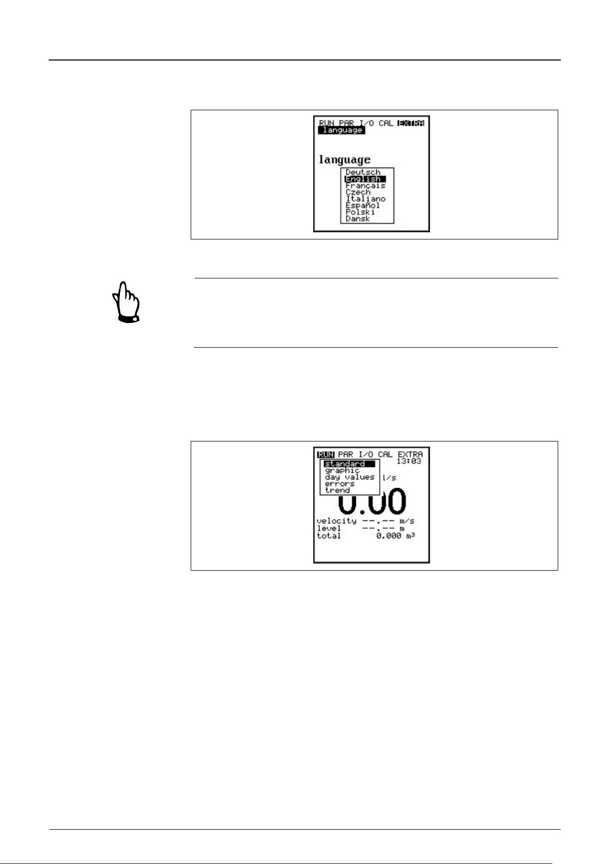
Instruction Manual
PCM F
Page 58 PCM F - Rev. 00 as of 24.10.2007
Standard
Display (basic screen) indicating information on the name of measurement
tity, level and
Graphics
The frequency histogram indicates the spreading of the investigated Doppler
The PCM F initial start-up dialog is the language selection:
Fig. 8-1 Language selection
A system reset shall be executed prior to each initial start-up in order to reset
the unit to default settings. This helps to prevent errors due to faulty settings.
Custom parameters will get lost performing a reset and the unit will reset to
factory defaults.
8.3 Operation Mode (RUN)
This menu is a display menu for standard operation mode. Containing the
following sub menus, it is not required for parameter setting:
Fig. 8-2 Operation mode selection
place, time (alternately appearing medium temperature), flow quan
average velocity.
frequency. Each bar (peak) represents a frequency group.
Considering shape and spreading of the frequency groups allows to draw
conclusions on the quality of the the flow velocity measurement.
This is particularly important to assess and to choose measurement places as
well as to find a place for sensor installation.
Page 58
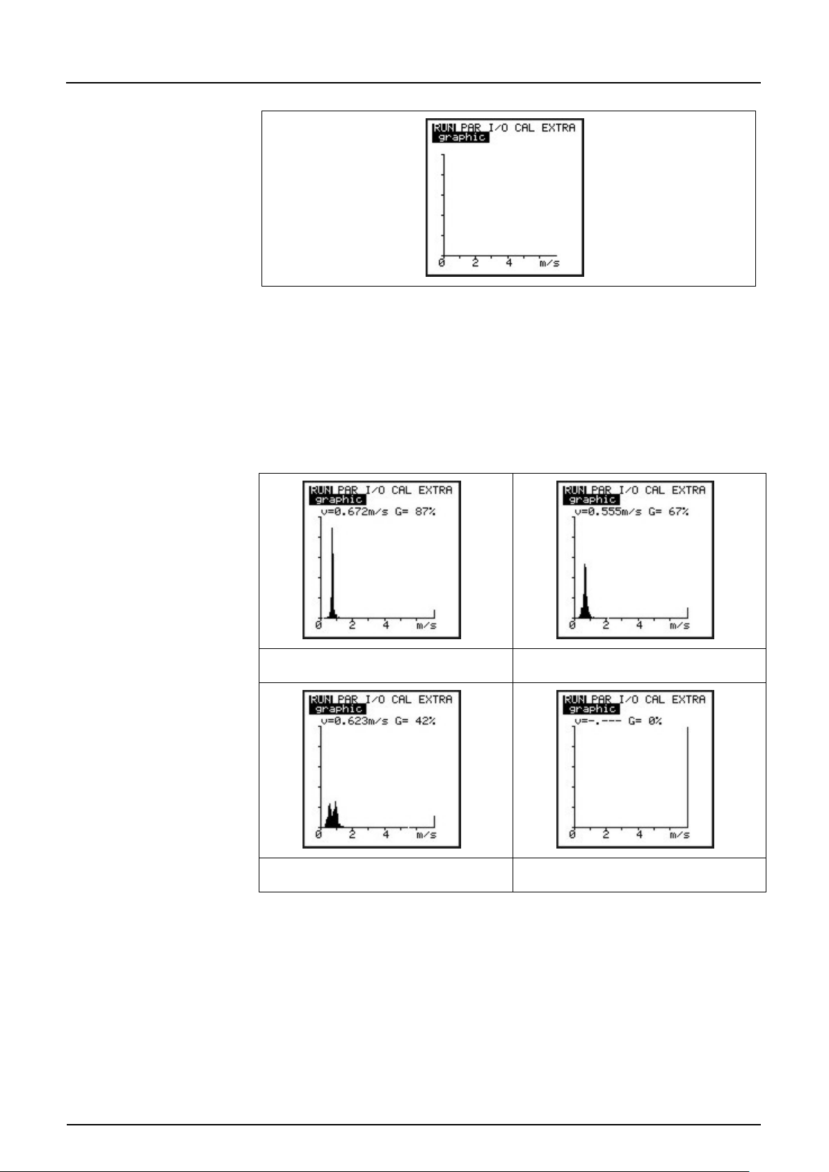
Instruction Manual
PCM F
PCM F - Rev. 00 as of 24.10.2007 Page 59
Day values
This menu is to indicate day total values.
Fig. 8-3 Distribution of frequency groups
The measurement quality (0-100 %) indicates the relation between the
evaluated Doppler frequency and the entire frequency spectrum measured. The
higher the quality, the more reliable the indicated flow velocity reading. There
are cases where, despite compar ative ly high qua lity values, it is not possible to
correctly investigate the flow velocity reading. Hence it is necessary to
additionally consider the shape of frequency distribution.
good Profile – no vorticity well-shaped
poor reflection quality no measurement possible
Fig. 8-4 Flow velocity profiles
Additionally, you can get information about partial total value since the last reset
(comparable with route mileage counters in cars).
Recall day total values of the past 7 days in the menu point >INFO<. The totals
(difference to previous day) are going to be saved internally for a period of 90
days. These data can be saved on compact flash card using the I/O menu.
Page 59
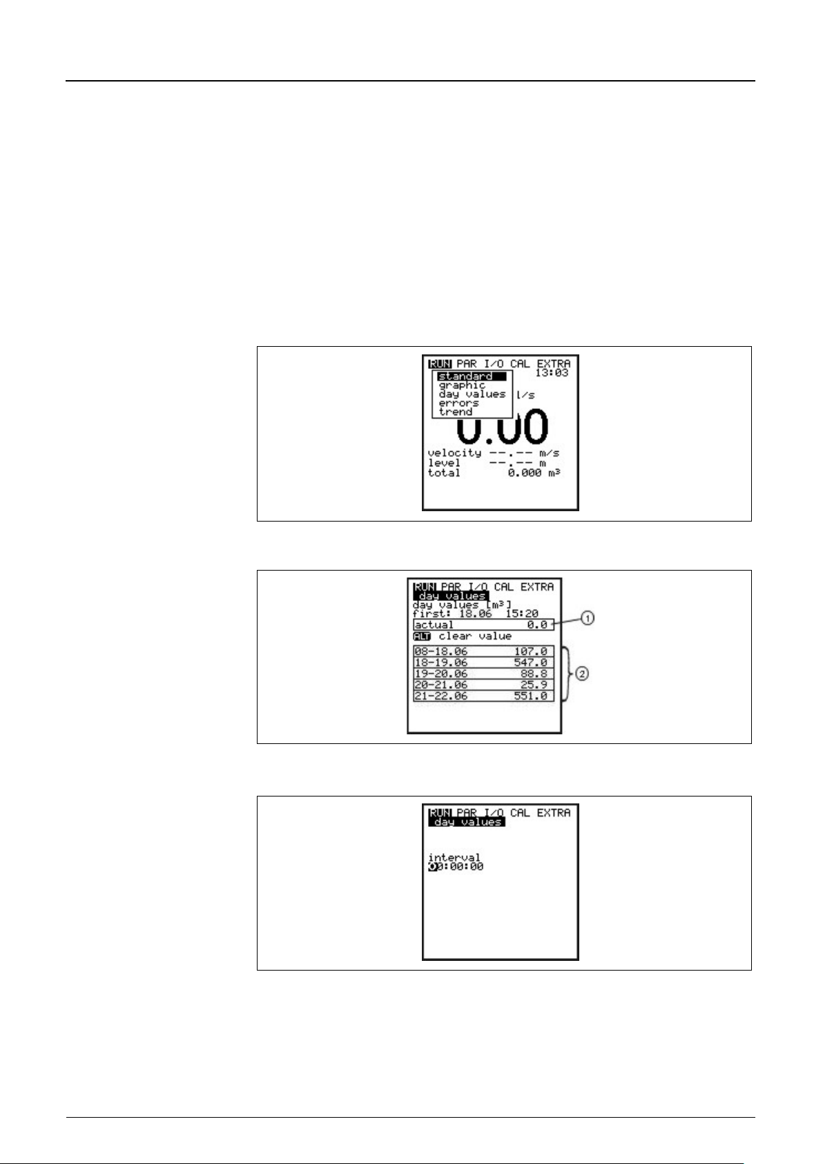
Instruction Manual
PCM F
Page 60 PCM F - Rev. 00 as of 24.10.2007
INFO
This menu contains the total flow values of the past 7 days (see Fig. 8-6),
eration)
Cycle
Totalisation normally is carried out at 00:00 h (midnight). If desired, this value
Erase memory
Erases the internal totaliser memory. The readings indicated on the display will
presumed the transmitter was operated without any interruption in the past
seven days. Otherwise it shows the total for the uninterrupted days of op
Reset to >0< by pressing the >ALT< key. This reset does not influence the
totaliser!
can be modified under RUN – Day Totals - Interval (see Fig. 8-7). The
modification however will influence totalisation of day values saved in the
internal memory (see Fig. 8-74).
not be influenced.
Fig. 8-5 Day total values menu
Fig. 8-6 Day totals
Fig. 8-7 Time of day totalising
Page 60
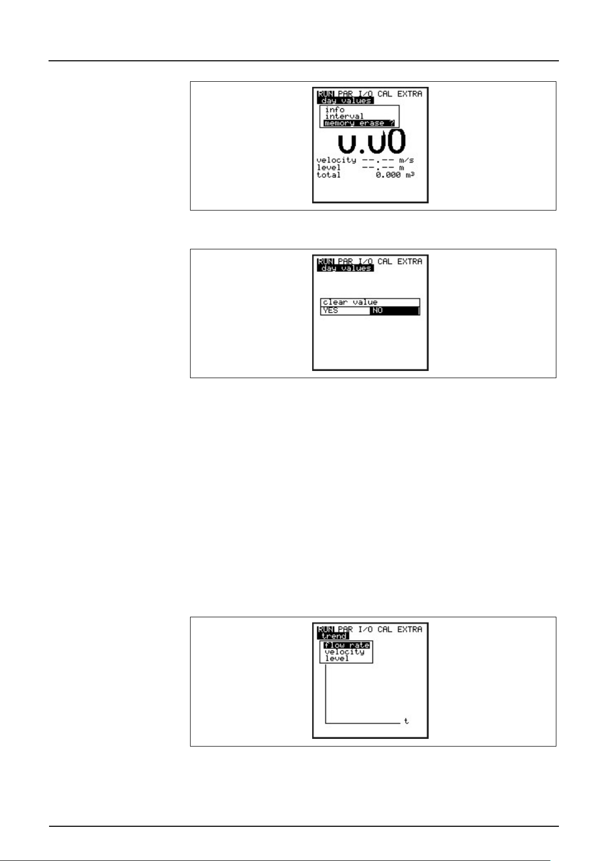
Instruction Manual
PCM F
PCM F - Rev. 00 as of 24.10.2007 Page 61
Errors
This menu is to monitor any interruptions in the unit function. Errors are going to
Trend
This menu operates like an electronic logger, saving cycle values on fill level,
Fig. 8-8 Erase memory
Fig. 8-9 Confirmation dialog
be saved and ordered by type of error, date and time. Pressing the >ALT< key
will delete all error messages one by one (from the latest one back to the oldest
one). To delete an error message is equivalent to confirming it. If the respective
error still is present in the moment of confirmation it is not going to be written
into the error memory again.
average flow velocity and height in an internal memory. The capacity of the
PCM F memory is capable to save readings for each minute within a period of
14 days.
The submenu allows to select and to watch individual trends. This enables to
quickly monitor past situations at measurement places on-site without any
additional aid.
Fig. 8-10 Selection of trend values
The bottom line indicates the period shown including date and time. Browse
through the periods (max. 14 days) by using the arrow-left or –right keys.
Page 61
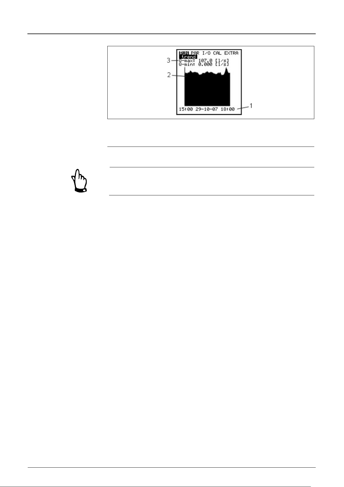
Instruction Manual
PCM F
Page 62 PCM F - Rev. 00 as of 24.10.2007
2 Trend graph
3 Maximum value / Minimum value
1 Period of indication
Fig. 8-11 Trend graph example
The content of the internal memory will get lost on executing a system reset.
All trend graphic values saved previously will get lost as well.
Page 62
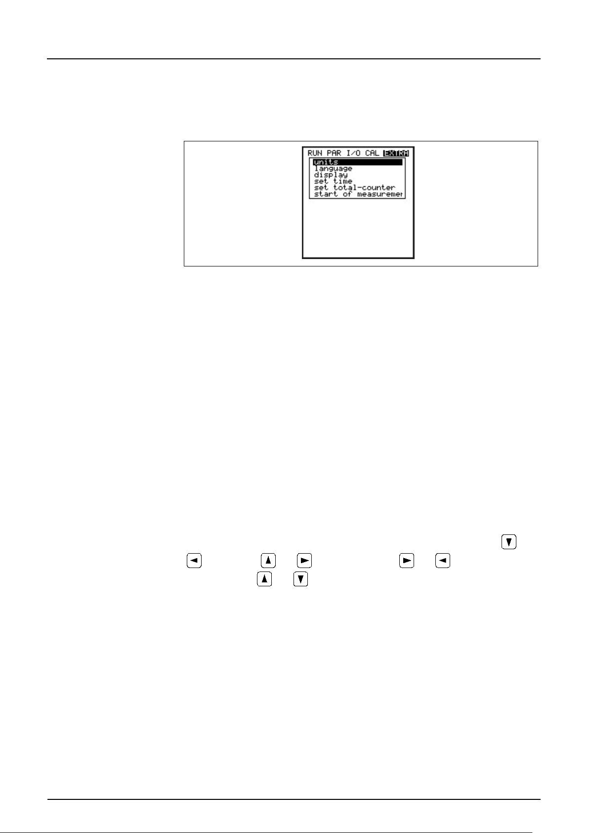
Instruction Manual
PCM F
PCM F - Rev. 00 as of 24.10.2007 Page 63
Units
Here you can select between the metric system (litre, cubic meters, cm/s etc.),
Sprache
Select from German, English, French, Italian, Czech, Spanish,
Display
and
Systemzeit ändern
In order to perform various control and memory functions, the unit includes an
8.4 Display Menu (EXTRA)
This menu allows to modify settings such as basic screen, units, language as
well as the display itself. The following submenus are available:
Fig. 8-12 Extra submen u s
English system (ft, in, gal/s, etc.) and American system (fps, mgd etc.).
These settings only have an effect on how units are indicated on the display and
do not influence the units which are to be saved on compact flash card. Modify
setting regarding the memory card under "Parameters -> Memory mode ->
Units“.
The next selection will come up automatically after confirmation.
For each one of the following metered or calculated values you can select a unit
appearing on the display:
Depending on the unit system selected there are various units available.
- Flow rate
- Velocity
- Fill level
- Total
Polish and Danish.
Allows to adjust display settings regarding contrast and brightness. Use
to decrease; and to increase values. and will modify settings
in steps of 5 %,
internal system clock saving dates of year, weekdays and week numbers. The
clock settings can be modified if required.
First select the menu point “Info”:
and in steps of 1 %.
Page 63
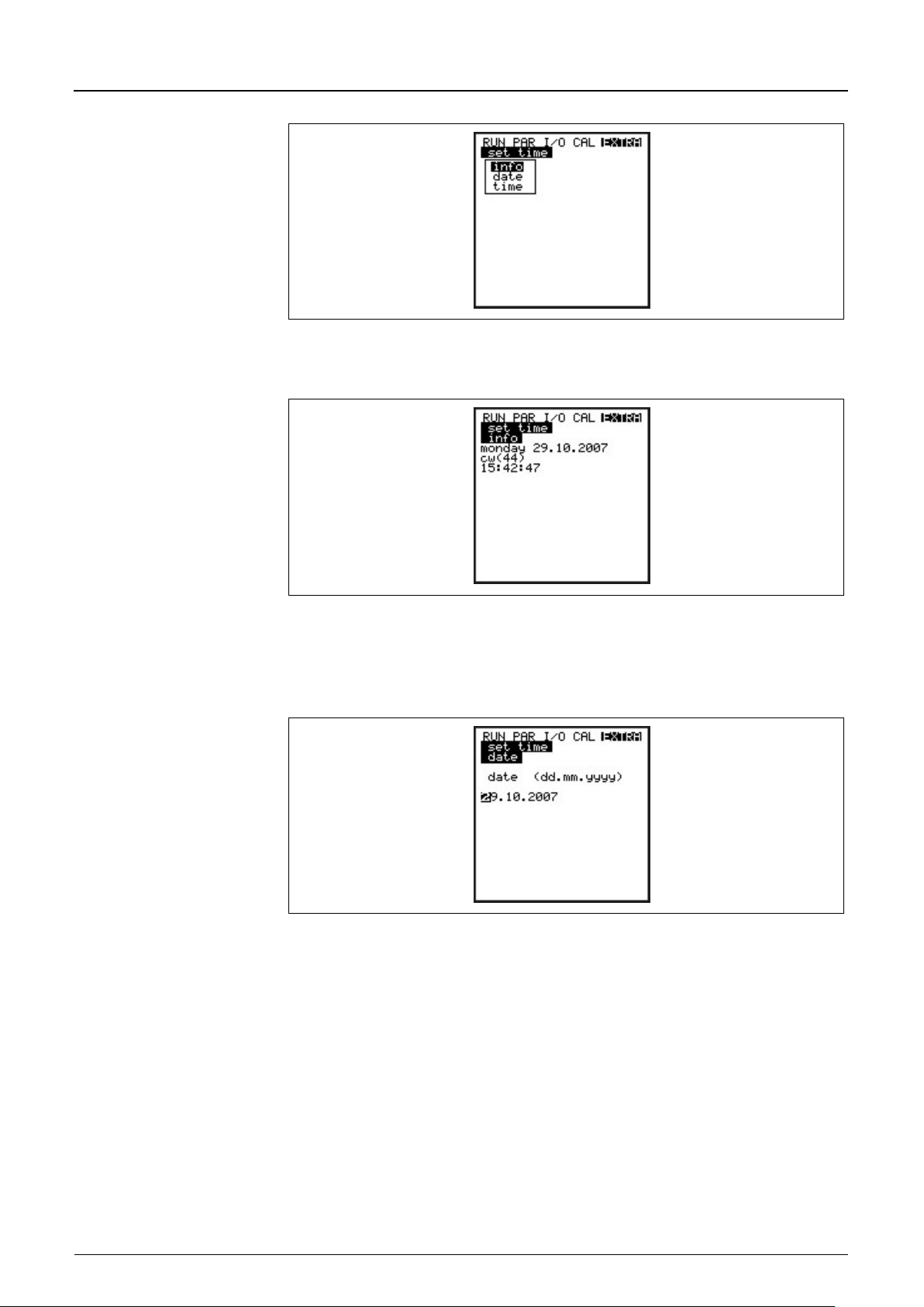
Instruction Manual
PCM F
Page 64 PCM F - Rev. 00 as of 24.10.2007
Set total-counter
Totaliser setting [m³]. Will be set to zero in case of executing a system reset.
Start of Measuring
In memory mode, this setting determines the delay if you do not wish the unit to
Fig. 8-13 System time submenu
The complete system time is indicated after the settings have been confirmed:
Fig. 8-14 Complete system time
This menu point is for indicating purposes only. Hence the clock cannot be
adjusted here. Modifications can be carried out only in the “Change time” menu.
Fig. 8-15 Setting the date
In menu points Set clock / Date and Time it is possible to set the date as well as
the time.
start measuring immediately after programming has been finished. If this setting
has not been modified the PCM F is going to start measuring immediately after
parameters have been set (if memory mode is active). Only full hours can be
selected!
Page 64
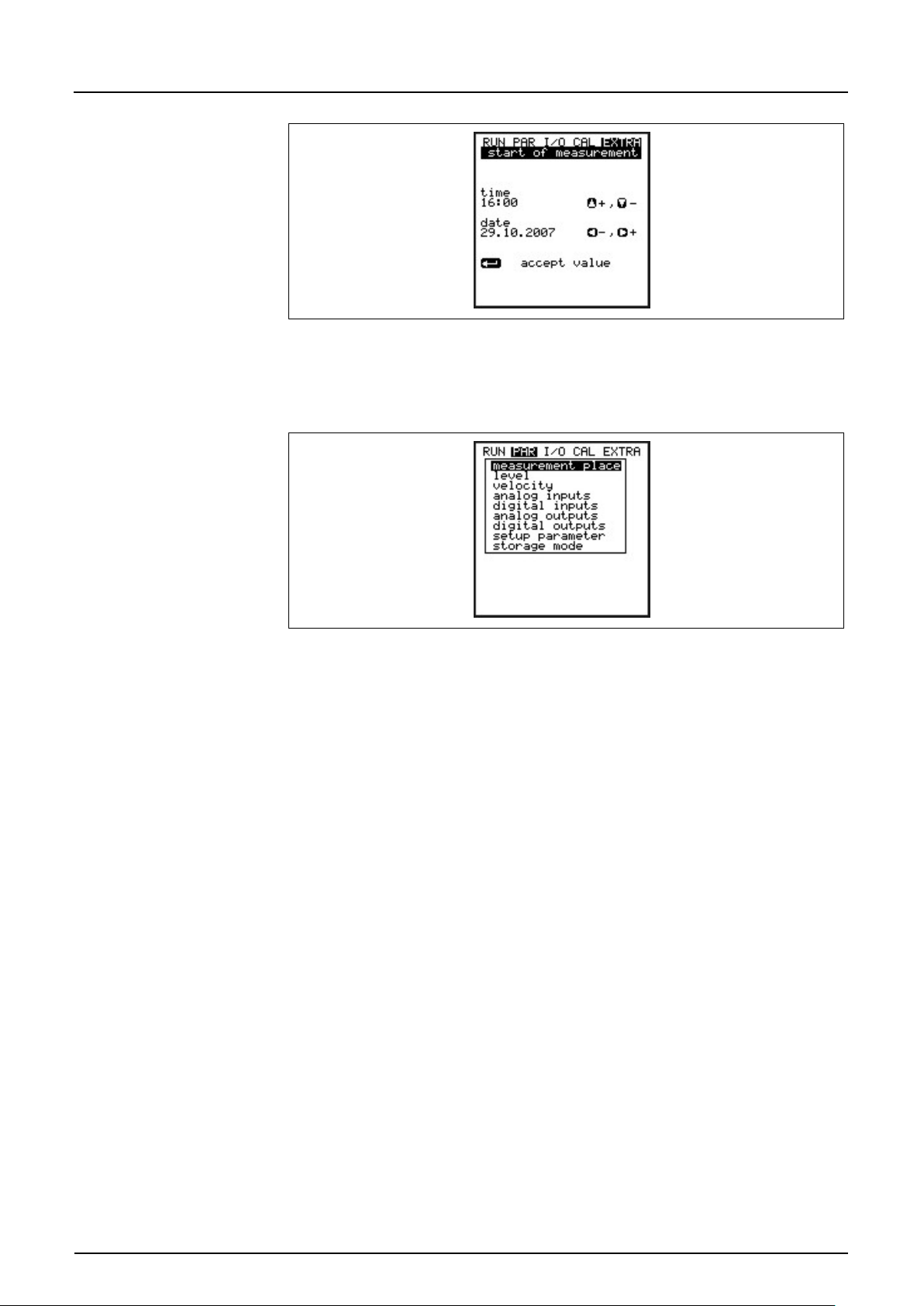
Instruction Manual
PCM F
PCM F - Rev. 00 as of 24.10.2007 Page 65
Fig. 8-16 Start of measu re m ent
8.5 Parameter Menu (PAR)
Fig. 8-17 Parameter menu
This menu is the most extensive and most important regarding the PCM F
settings. It nevertheless is sufficient in most cases to set only some essential
parameters, which usually are:
- name of measurement place
- channel shape
- channel dimensions
- sensor type
- storage mode
All other functions are additions which are required in special cases only.
Page 65
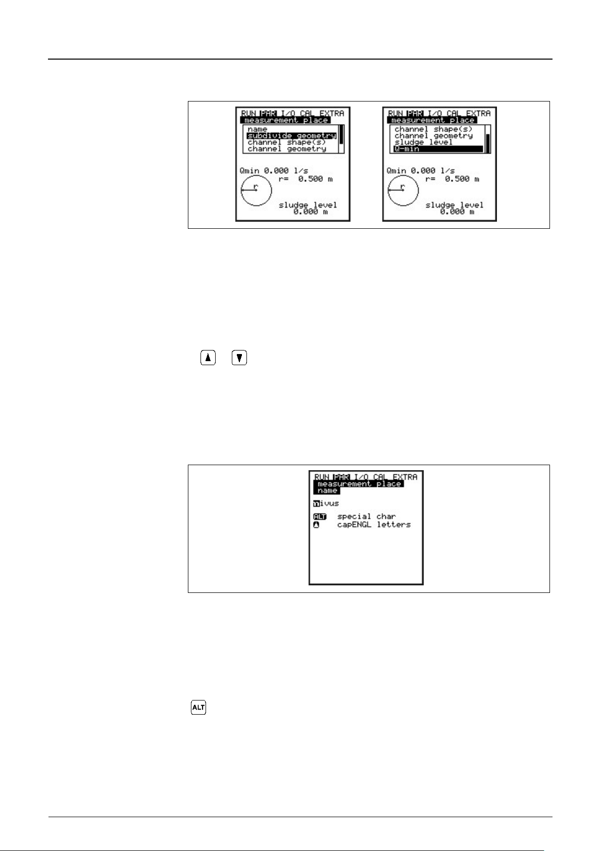
Instruction Manual
Page 66 PCM F - Rev. 00 as of 24.10.2007
Use "Up“ and "Down“ keys to scroll the menu.
Measurement place
NIVUS recommends to coordinate and to define names according to names
contain up to 21 letters. Setting
Lets you optionally select special characters which are not
8.5.1 Parameter Menu "Measurement Place“
Fig. 8-18 Submenu measurement place
This menu is one of the most important basic menus for parameter setting as the
dimensions of the measurement place are going to be defined here.
The menu cannot be indicated completely due to restricted display space.
Similar to many well-known PC applications, this is readily identifiable from the
black bars on the right-hand side of the screen.
PCM F
name
stated in the respective documents. Names may
the name is quite similar to operating a mobile phone:
After the submenu >Name of Measurement Place< has been selected the basic
setting “nivus“ will come up.
Fig. 8-19 Setting the name of the measurement place
Enter the desired name with the keypad, where each key has assigned three
letters and a number. Select between these four characters by briefly pressing a
key several times. The cursor will jump to the next character if no keys have
been pressed for two seconds.
available on the keypad (such as >ä<, >ö<, >ü<, >ß<). More
special characters will be indicated but however are not allowed
to be used as measurement place names. The signs can be
used to specify inputs and outputs.
Page 66
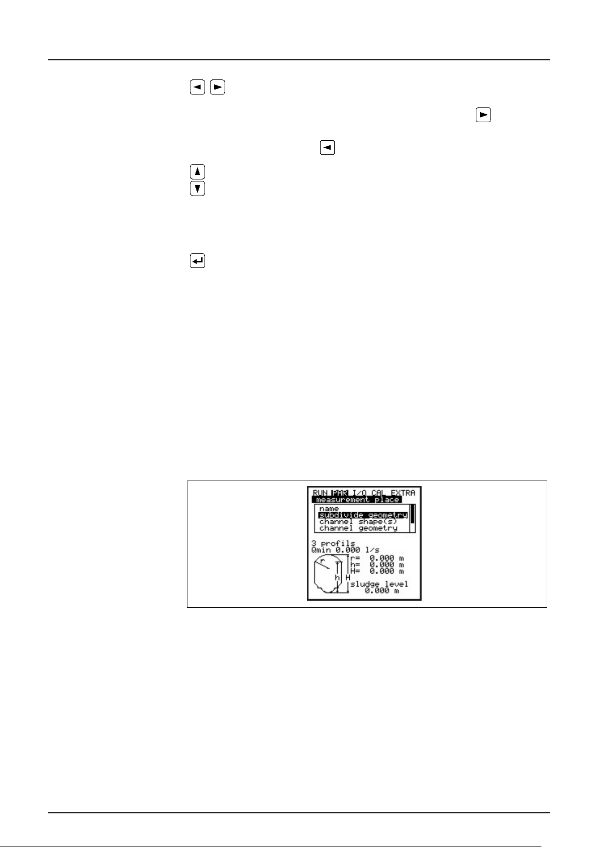
Instruction Manual
PCM F
PCM F - Rev. 00 as of 24.10.2007 Page 67
These keys move the cursor left or right within the special
Shift to uppercase letters
Shift to lowercase letters
Confirm the entered name with “Enter“ and exit the menu.
Subdivide geometry
This is a special parameter which enables to easily set parameters for large
Channel shape(s)
If the profile has been subdivided, first select the zone (bottom, centre, top)
character menu.
Moving the cursor to the right-hand side with the - key
creates a space character if in uppercase or lowercase menu.
Pressing the
-key will delete the previous character.
Faulty entries can be corrected by moving the cursor back and overwriting the
character accordingly.
special profiles with convex tops. This parameter however will not be required in
98% of all cases!
Pressing the >ALT< key will switch between the 3 options described below:
- NO (no profile subdivision)
- 2 (subdivide in 2 level / height zones)
- 3 (subdivide in 3 level / height zones)
Zones can be set under Parameter/Measurement Place/Channel Profile(s).
The bottom zone of the profile can be set to Pipe, Egg, Rectangle,
U-Profile, Trapezoid, 2r Egg and Q = f(h). Set a height-width or a height-area
characteristic in the centre zone and enter a segment of circle in the top profile
zone. During setting the profiles please observe that the reference point is
always the channel bottom.
Fig. 8-20 Profile divided into 3 zones
using the ALT key and set the desired profile subsequently. Current ly it is
possible to select from following standard profiles according to ATV A110:
- Pipe
- Egg (standard; h:w = 1.5:1)
- Rectangle
- U-Profile
- Trapezoid
- Custom shape
- 2r Egg (h:w = 1:1) and
- Q= f(h)
Page 67
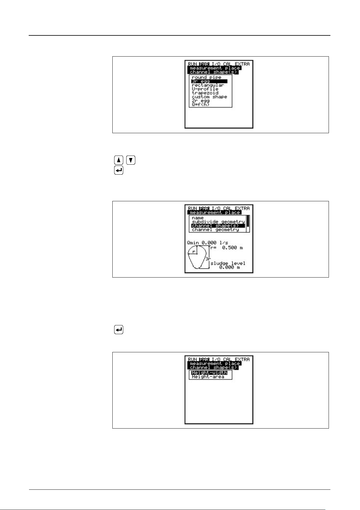
Instruction Manual
PCM F
Page 68 PCM F - Rev. 00 as of 24.10.2007
Select channel shape with "Up“ and "Down“ keys.
Confirm selection with “Enter“.
Confirm with “Enter“.
Channel geometry
Type in the respective channel dimensions depending on the previously chosen
Fig. 8-21 Select channel shape
The selected profile will be indicated in the programming mode screen.
Fig. 8-22 Selected profile
If the existing profile does not comply with the options to select from, choose
>Custom shape< in this case.
A request will come up subsequently asking for known relations.
Fig. 8-23 Custom shape menu
profile.
Page 68
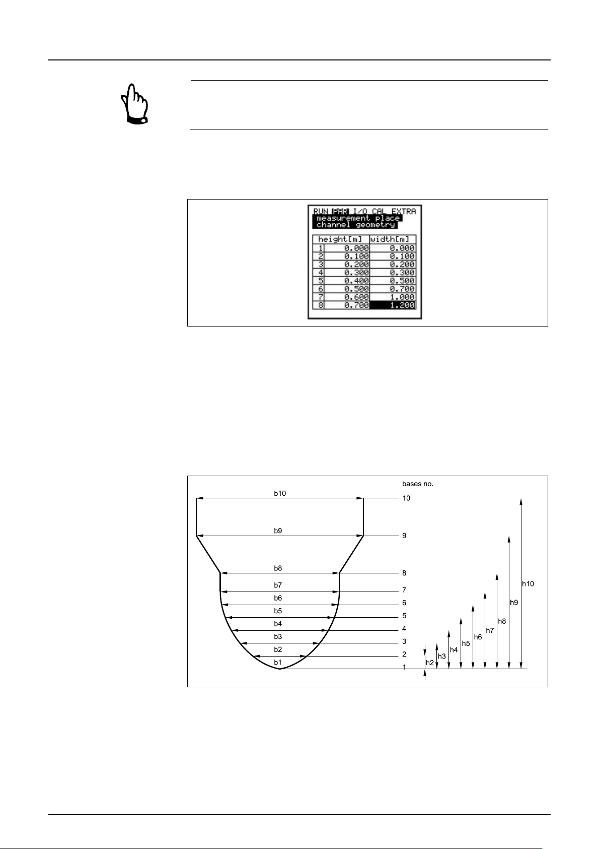
Instruction Manual
PCM F
PCM F - Rev. 00 as of 24.10.2007 Page 69
Please observe indicated units!
Choosing >Custom shape< will indicate a table of 32 possible breakpoints on
the display. As described above, enter the relations between height-width or
height-area and enter the according value pairs.
Fig. 8-24 List of custom shape breakpoints
In order to define the zero point of the channel start by entering 0 – 0 in
breakpoint 1. All further break point can be set fr eely re gardi ng hei ght as well as
width/area. There may be different distances between individual level points.
Furthermore it is not required to use all of the 32 breakpoints possible.
The PCM F however is going to use a linearisation function between the
breakpoints. Decrease the distance between breakpoints in case of heavy and
irregular fluctuation within the area.
Fig. 8-25 Custom profile breakpoints
If the channel profile has been divided in two zones, the channel profiles below
are available to be set:
Page 69
Instruction Manual
PCM F
Page 70 PCM F - Rev. 00 as of 24.10.2007
Bottom area:
Pipe
Top area:
Custom profile
Bottom area:
Pipe
Centre area:
Custom profile
Top area:
Sludge Level
The sludge level set is going to be calculated as non-moving channel sub-area
Low-Flow Volume
This parameter serves to suppress lowest movements or apparent volumes
Q
: measurement values lower than this one will be set to >0<. Only positive
V
: low-flow volumes in applications with large profiles and filling levels can be
-
- Egg
- Rectangle
- U-Profile
- Trapezoid
- 2r Egg
Q=f(h)
-
Dividing into three zones will reveal the following setting options:
-
- Egg
- Rectangle
- U-Profile
- Trapezoid
- 2r Egg
Q=f(h))
-
- Pipe
If the function Q=f(h) has been selected only one level zone can be defined,
i.e. it is not possible to divide into centre area or top.
Programming subdivided profiles makes sense only case of exceptional and
very unusual profiles with convex tops. The procedure requires
comprehensive knowledge and experience in operating the PCM F. To avoid
faulty programming or if in doubt this procedure should be performed by
NIVUS service personnel or expert companies authorised by NIVUS.
and will be subtracted from the wetted hydraulic total area prior to executing
flow calculation.
arising.
min
values are allowed to be set. These values are going to be considered as
absolute values and therefor e have positive as well as negative effects.
min
suppressed by means of this parameter. Lowest velocity fluctuations within
longer periods of time may cause apparently large volume fluc tuatio ns which
cannot be gated by using the value of Q
min
.
Flow velocities below this value will be set to “0“ which will set the calculated
volume to “0“ as well.
Both setting options of low-flow suppression have an OR relation between each
other. This means that the low-flow volume suppression is enabled as soon as
Page 70
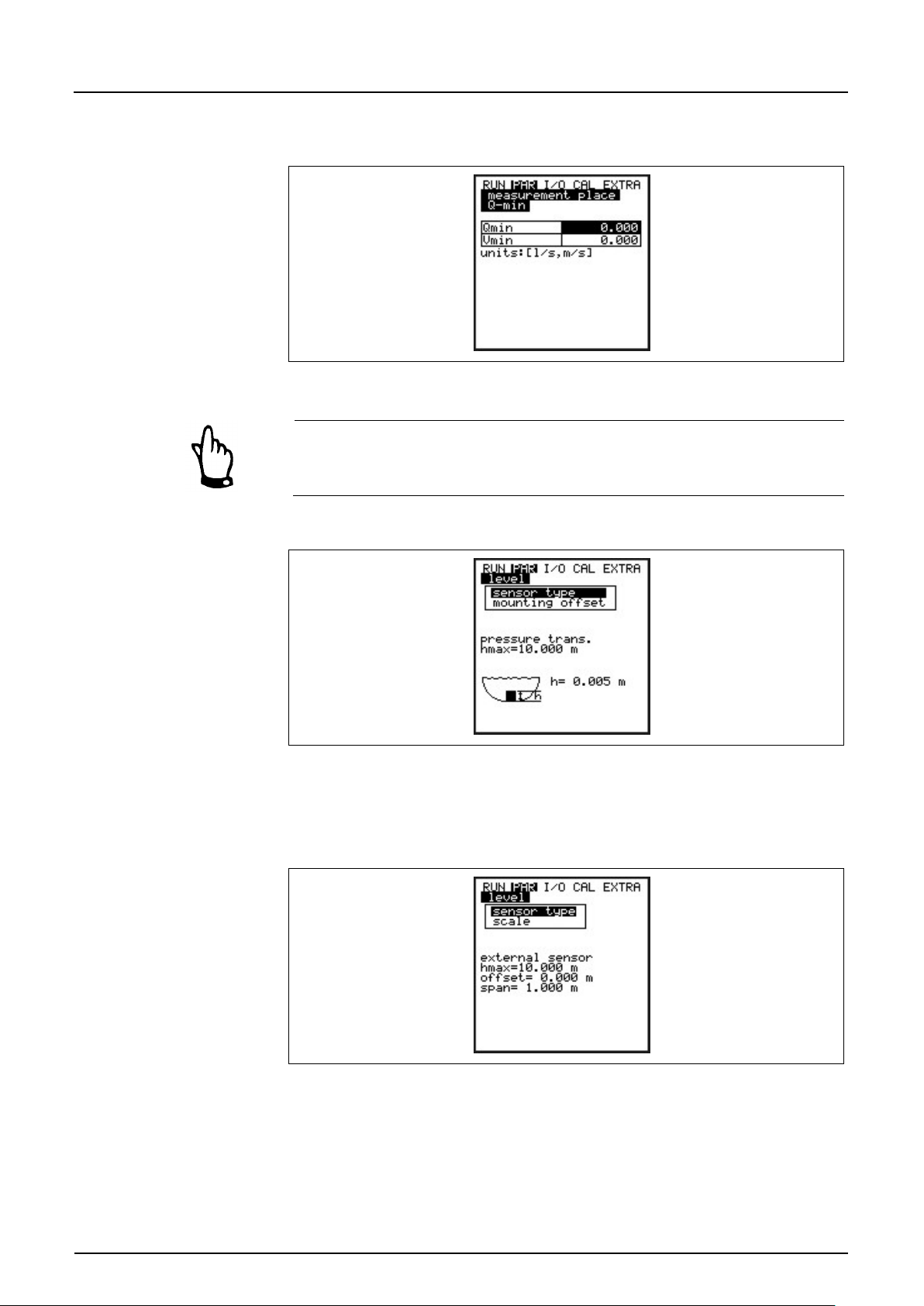
Instruction Manual
PCM F
PCM F - Rev. 00 as of 24.10.2007 Page 71
8.5.2 Parameter Menu "Level “
one or both parameters are not equal to zero. The first parameter whose value
goes below the limit will take effect if both parameters have been set.
Fig. 8-26 Selection l o w-flow volumes
The suppression of low-flow volumes is no offset but a limit value.
Fig. 8-27 Level measurement – submenu
This menu defines any parameter regarding level measurement. The start
screen depicted below as well as the parameters to be set may vary depending
on the sensor type selected.
Fig. 8-28 Example screen: external Sensor
Page 71
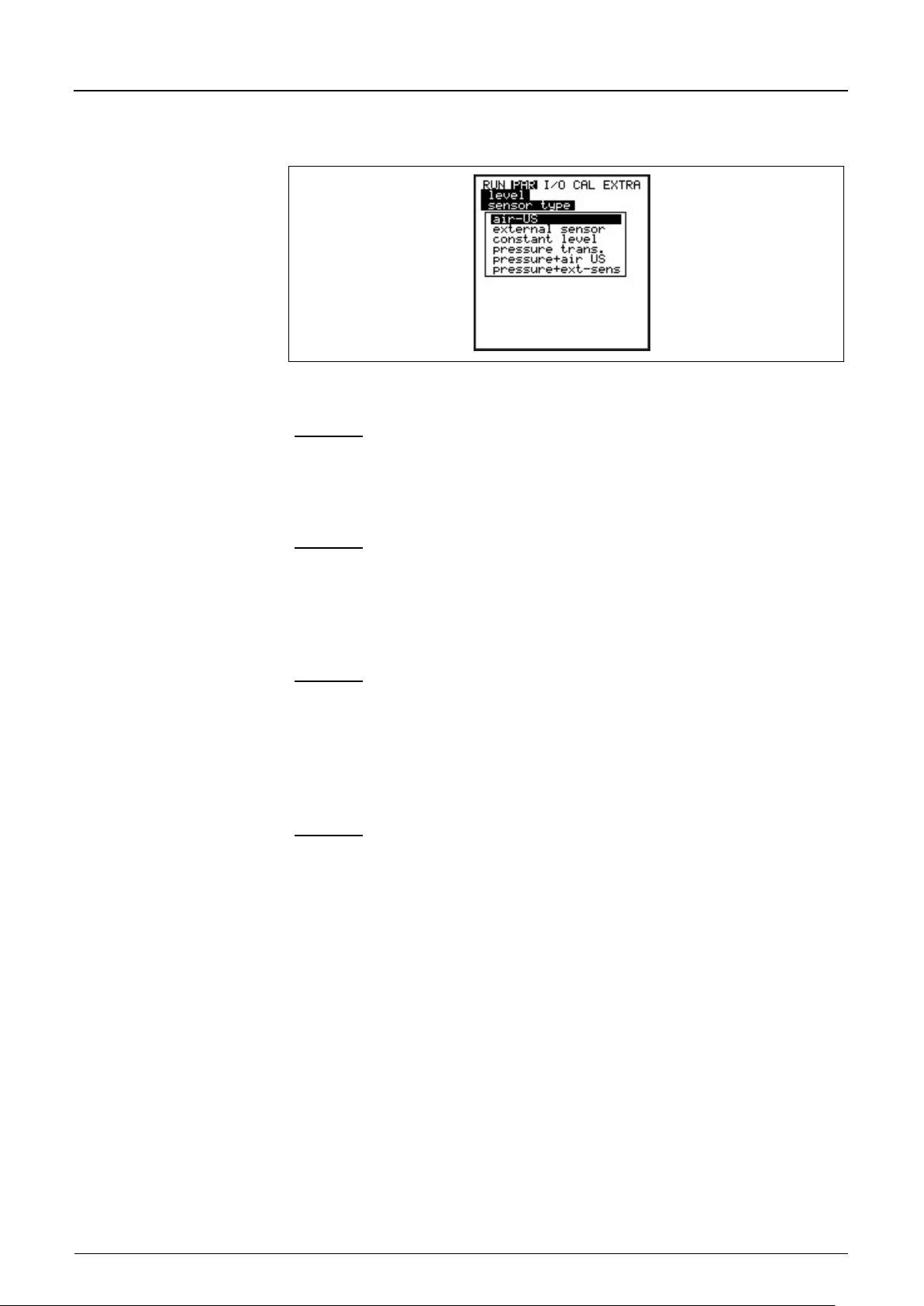
Instruction Manual
PCM F
Page 72 PCM F - Rev. 00 as of 24.10.2007
Pressure + Air-US
Combination of options 1 and 4. Recommended if an area from flow level
Pressure + ext. Sensor
Combination of options 2 and 4. Same applications as described under
First of all determine the sensor type. Select from the types below:
Fig. 8-29 Defining the sensor type
Option 1: Air-Ultrasonic (Air-US)
Air-ultrasonic fill level measurement from top down. Flow rate calculated by
exclusively using a Q = f(h) relation without additional flow velocity sensor. The
sensor however may be combined with the flow velocity sensor.
Option 2: External Sensor
Level measurement by external 2-wire sensor supplied by PCM F (such as
NivuBar Plus or NivuCompact). Flow rate calculated by exclusively using a
Q = f(h) relation without additional flow velocity sensor. The sensor however may
be combined with the flow velocity sensor.
Option 3: Fixed Value
This option is going to be used for constantly filled pipes and channels
(e.g. NPP). Such applications normally do not need level measurements. Set the
constant fill level under „Scale/Height“.
This parameter is useful in case of testing or initial start-ups if there is no level
reading available.
Option 4: Pressure
Flow velocity and level measurement using a combi sensor with integrated
pressure measurement from bottom up.
It is possible to combine different options as described below. These
combinations may be required if due to constructional conditions a single sensor
does not cover the entire measurement range.
0 mm up to additional impoundment must be measured.
The pressure sensor covers the range of additional impoundment and the airultrasonic sensor detects the low flow levels.
Pressure sensor can be installed out of the channel centre due to heavy
sedimentation.
pressure + air-US
Page 72
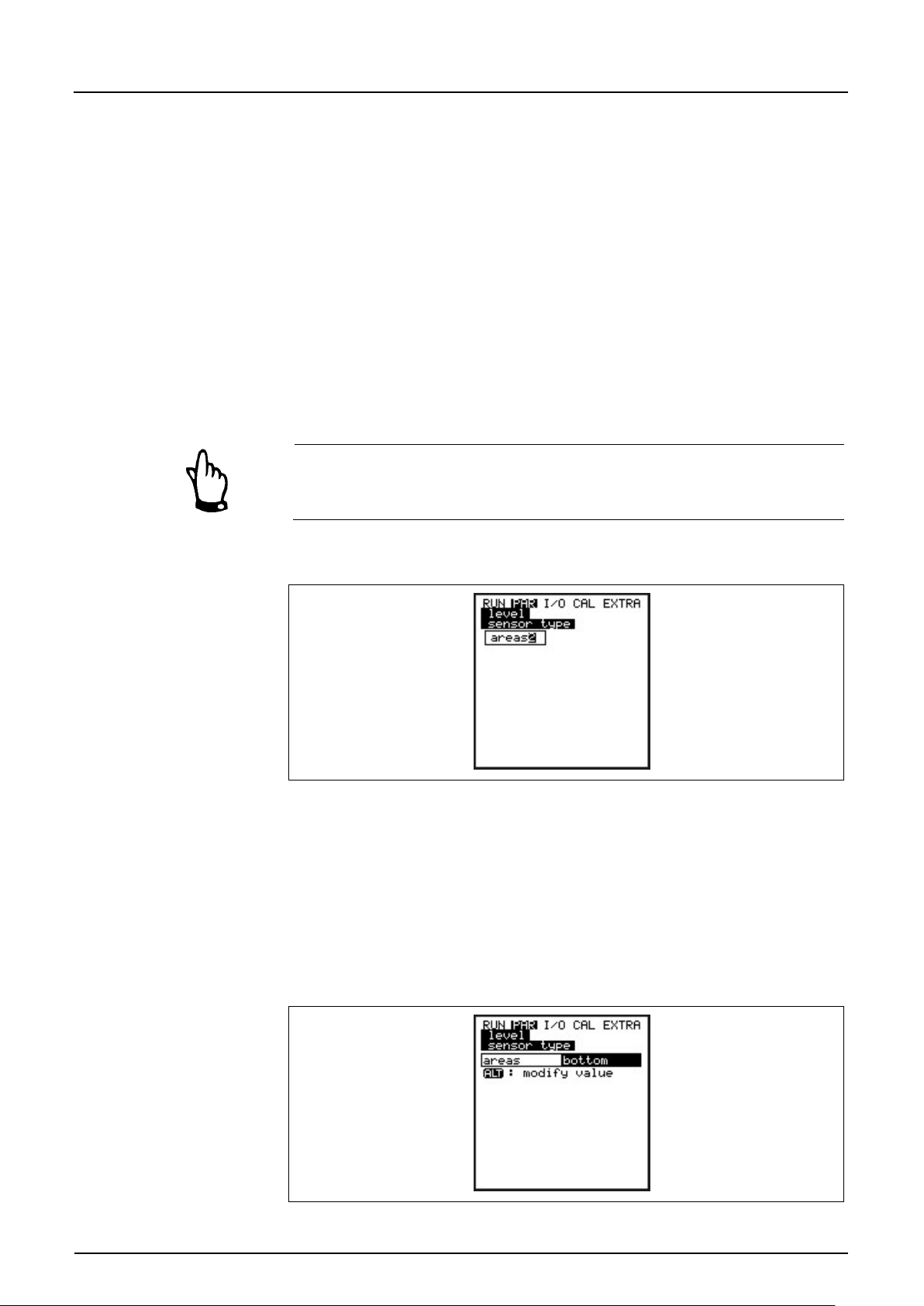
Instruction Manual
PCM F
PCM F - Rev. 00 as of 24.10.2007 Page 73
Mounting offset
If selecting the pressure sensor the value is set to 5 mm (0.2 in) per default
Scale
Depending on the sensor type set either measurement offset, measurement
Delay time
Indicated only if “External sensor“ has been selected.
Select layers
This parameter will be indicated only if a sensor combination has been selected
which is equivalent to the sensor installation height.
The according installation level will be adjusted if calibrating the level in CAL menu.
span and delay or a fixed fill level (which is equivalent to the input signal) is
going to be entered.
The sensors will be powered during the delay time after the PCM F has been
turned on, no measurement is carried out however. This is the time the
sensors require to run stable.
Please refer to chapter 6 for sensor connection.
Fig. 8-30 Split level zones
It is possible to split the fill level in two (top and bottom) or three zones (top,
centre, bottom). This enables to measure e.g. the bottom zone by using an airultrasonic or an external sensor and the top zone by using the sensor-inzegrated
pressure cell in order to obtain current fill level or flow volume. The previously
selected sensors may be assigned to the free definable range limits.
The threshold for switchover between the zones will be determined in the upper
or lower area under >Switchover level<.
Fig. 8-31 Setting the zones
Page 73
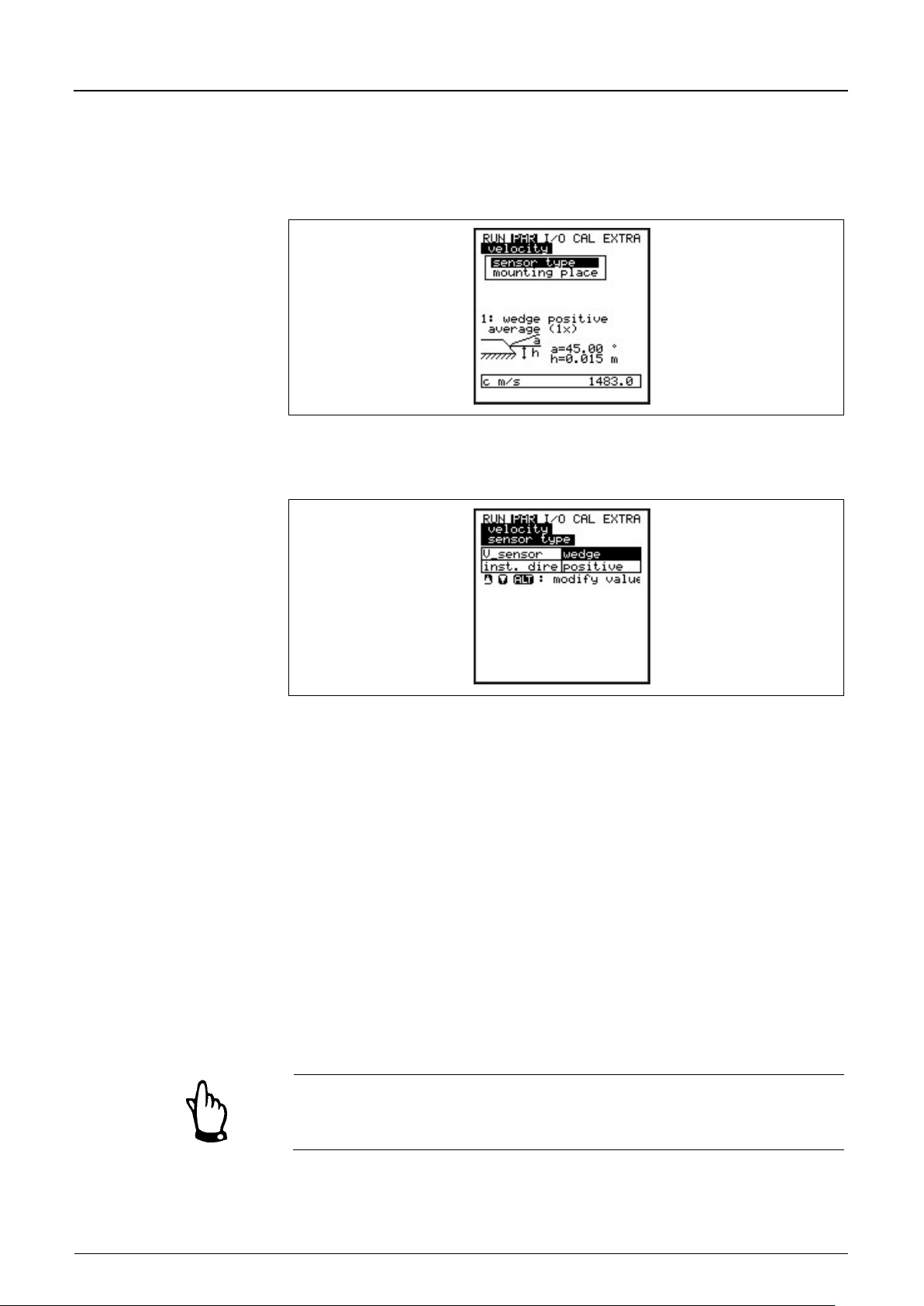
Instruction Manual
Page 74 PCM F - Rev. 00 as of 24.10.2007
Sensor type
Select between wedge or tube sensor by pressing the >ALT< key.
w velocity sensor
Mounting Place
This menu point is to modify the installation height of the flow velocity sensor.
8.5.3 Parameter Menu “Flow Velocity“
The PCM F allows to use a connected flow velocity sensor as combi sensor with
integrated level measurement (Type KP) or as flow velocity sensor (Type K0).
Fig. 8-32 Sensor settings
The sensor selection will bring up the screen below:
PCM F
Fig. 8-33 Selecting the sensor type
Installation position is set to “positive“ per default. This parameter should not be
modified!
It is going to be used only for special applications where the flo
is heading upstream (unlike heading downstream towards the flow direction as
in standard applications) but is to detect positive velocities however. This is the
only case which requires to set “negative“ here.
The standard setting is 15 mm (0.59 in), which is equivalent to the position of
the sensor centre above the channel bottom. This setting does not need to be
modified unless the sensor has been installed higher or lower. If the sensor has
been installed higher, input the additional mounting height plus 15 mm (0.59 in)
and enter overall height..
If the mounting place of the level sensor has been modified please necessarily
increase the value in parameter >Cal/Flow velocity//h_crit< by the same
amount.
Page 74
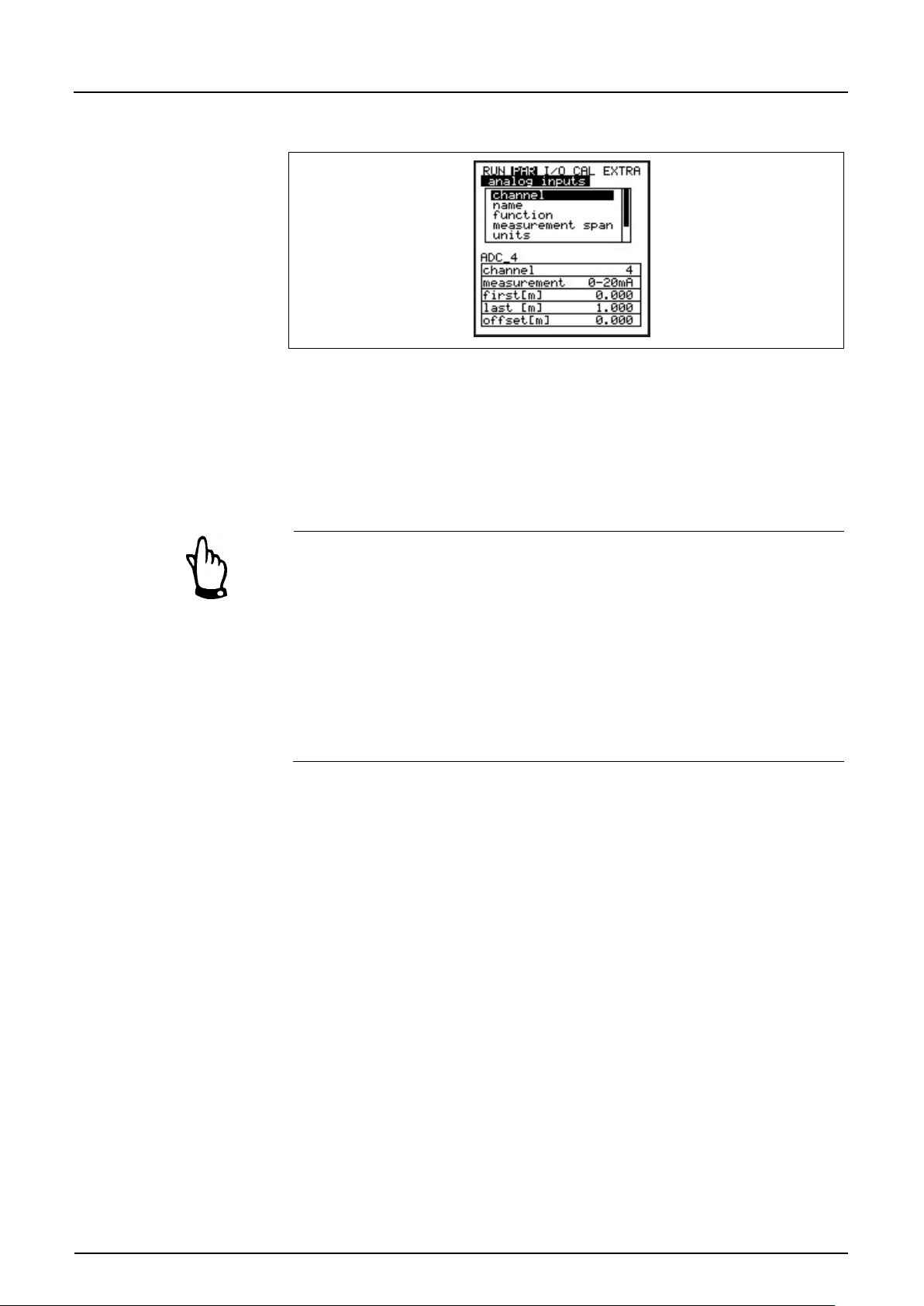
Instruction Manual
PCM F
PCM F - Rev. 00 as of 24.10.2007 Page 75
Channel Number
The PCM F has two programmable analog inputs available.
Name
Does not have to be entered. It is helpful to set a name if the analog input
Function
A function will be assigned to the analog input which has been selected using
Measurement Span
0/4 – 20 mA
Unit
This parameter is going to be assigned to the saved name and to the breakpoint
8.5.4 Parameter Menu “Analog Inputs“
Fig. 8-34 Submenu analog inputs
Channel 1: input via socket 3 (2-wire signal, supplied by PCM F)
Channel 4: input via socket 1 (2-wire signal, input is passive)
Channels 2 and 3 are reserved to measure battery voltage and current power
consumption. These channels cannot be programmed.
In case of connecting an external echo sounder fill level sensor (e.g. for level
measurement in basins for throttle verification) it is necessary to extend the
PCM F measurement delay. Echo sounder sensors normally require several
seconds to receive a stable ultrasonic signal.
Extend the measurement delay by modifying the parameters below:
Par -> Level-> Sensor type-> assign sensor/s used with “External sensor“.
Do not assign this “External sensor” to an area in the following assignment
dialog. This setting will extend the measurement delay from approx 4 sec. to
18 sec. in order to stabilise the echo sounder signals.
values are to be saved on memory card. This name will be saved on the storage
medium.
Set the name as described under PAR/Measurement place/Name of
measurement place<.
>Channel Number<. Select from following functions by pressing the >ALT< key:
- analog input disabled
- archive value (analog input will be saved [data logging function of
transmitter])
-
list explained below.
Page 75
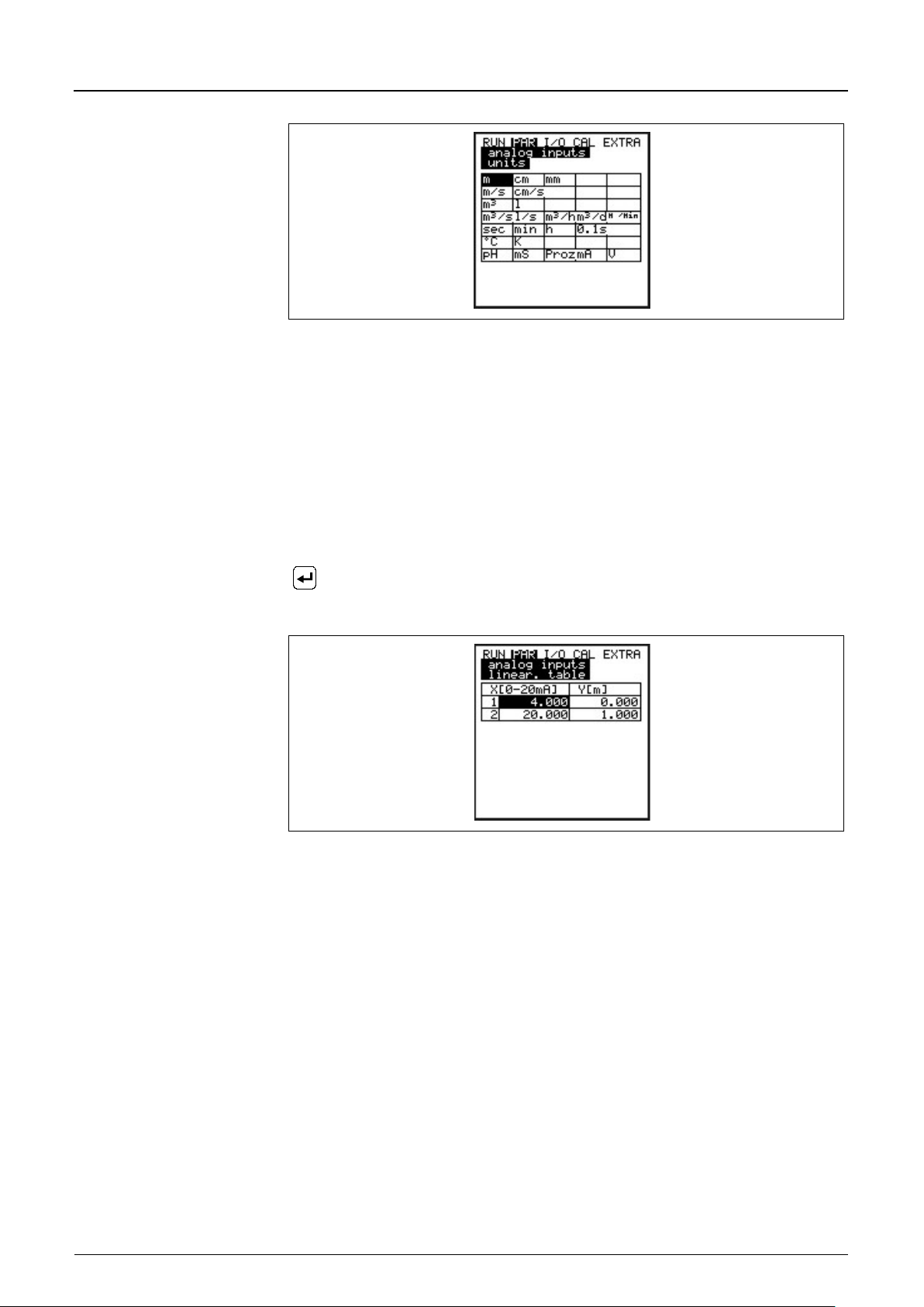
Instruction Manual
PCM F
Page 76 PCM F - Rev. 00 as of 24.10.2007
Linearisation
The analog input span can be defined here. Additionally it is possible to modify
point table.
Offset
In addition to the input current, a fixed positive or negative offset using the unit
Fig. 8-35 Table of measurement units
the weighting of the analog input by means of a 16-digit (max.) break
If used properly, this point will open up some helpful special options regarding
the setting of PCM F parameters. For example it is possible to convert a
level/height signal into a volume-proportional signal which can be saved or to
route this signal to one of the analog outputs for further processing or display
purposes.
Just enter the number of breakpoints.
Confirm entry!
A table with the respective units will come up subsequently.
Fig. 8-36 Table of values for analog input span
Enter the mA value in the X-column and the other value in the Y-column
(appropriate unit has been selected before under "Units“).
In case of classic applications such as setpoint input or in order to save a
measurement value just enter "2“ as breakpoint value. Subsequently define the
analog input span, i.e. enter the respective values for 4 mA and 20 mA.
chosen before can be added to the analog value.
Page 76
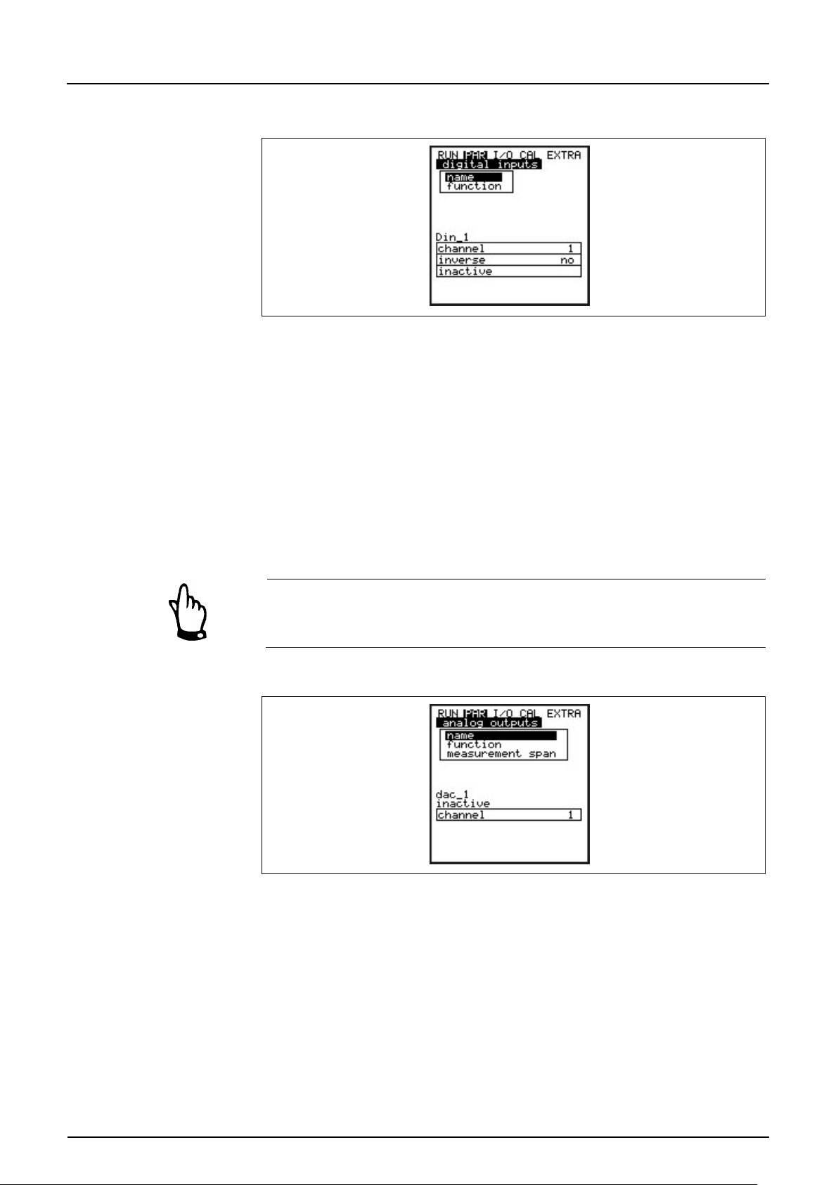
Instruction Manual
PCM F
PCM F - Rev. 00 as of 24.10.2007 Page 77
Name
It is not necessary however to input a name as it currently is for device-internal
Function
One of the following functions is going to be assigned to the digital input:
Name
Does not have to be entered as the name is for internal use currently. Set the
Function
One of the following functions is going to be assigned to the analog output:
- output flow (will output an analog signal which is proportional to the
8.5.5 Parameter Menu "Digital Inputs“
Fig. 8-37 Submenu digital inputs
use only.
Set the name as described under >PAR/Measurement place/Name of
measurement place<.
- disabled
- runtime
The transmitter detects switching events via the digital input even in stand-by
mode (between measurement cycles) and accurately saves the runtime to the
second.
The digital input is enabled and powered with a voltage of 3.3 V DC.
8.5.6 Parameter Menu "Analog Outputs“
Fig. 8-38 Submenu analog outp u ts
The analog output is a 0-10 V voltage output.
Determine the functions of the analog output in this menu.
name as described under PAR/Measurement place/Name of measurement
place<.
- disabled (no signals from analog output)
Page 77
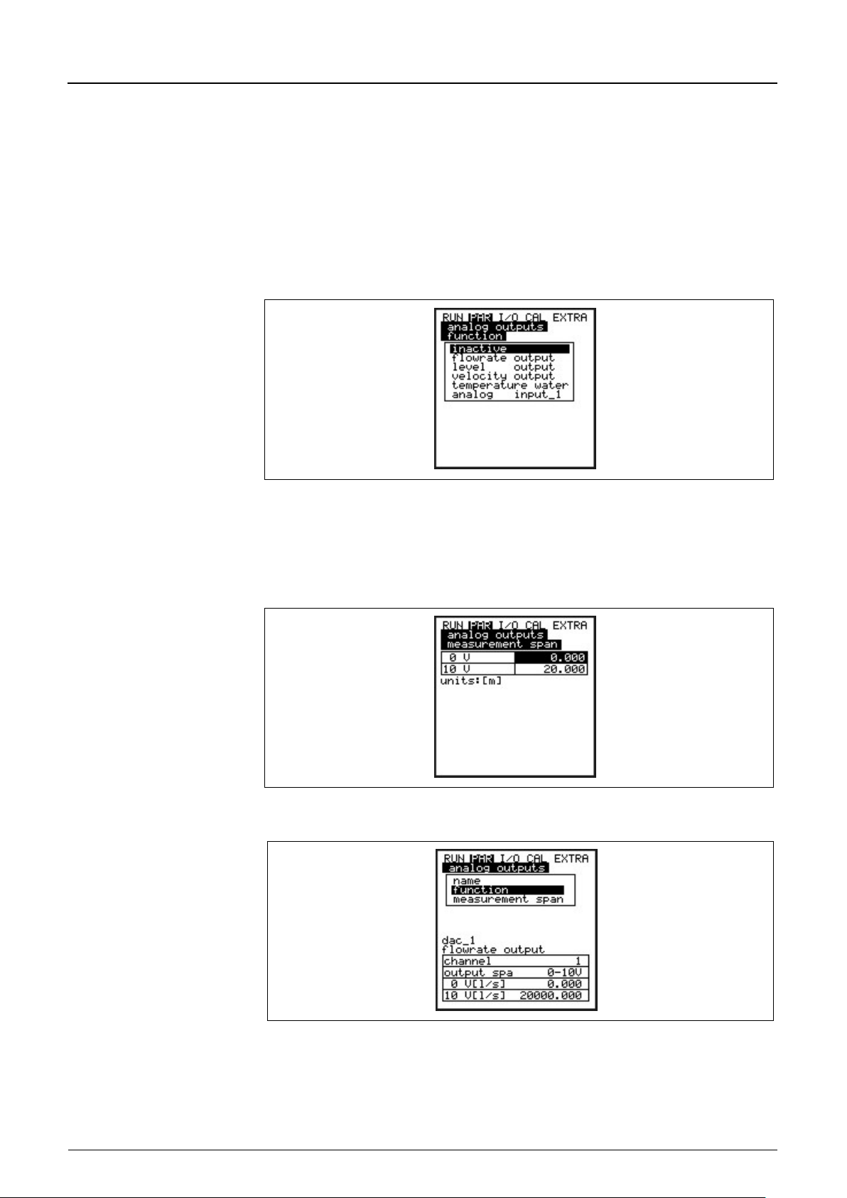
Instruction Manual
PCM F
Page 78 PCM F - Rev. 00 as of 24.10.2007
calculated flow volume)
Measurement Span
Define the values of the output signal here. Input in the units selected under
- output level (will output an analog signal which is proportional to the
calculated fill level)
- velocity (will output an analog signal which is proportional to the average
flow velocity calculated from single velocity readings)
- water temperature (will output the water temperature reading as analog
signal)
- analog input 1 (will output the value from analog input 1 which m ight have
been changed by a characteristic)
Fig. 8-39 Selecting analog output functions
menu "Extra“.
Negative values can be entered as well!
Fig. 8-40 Measurement span
Fig. 8-41 Screen after settings have been made
Page 78
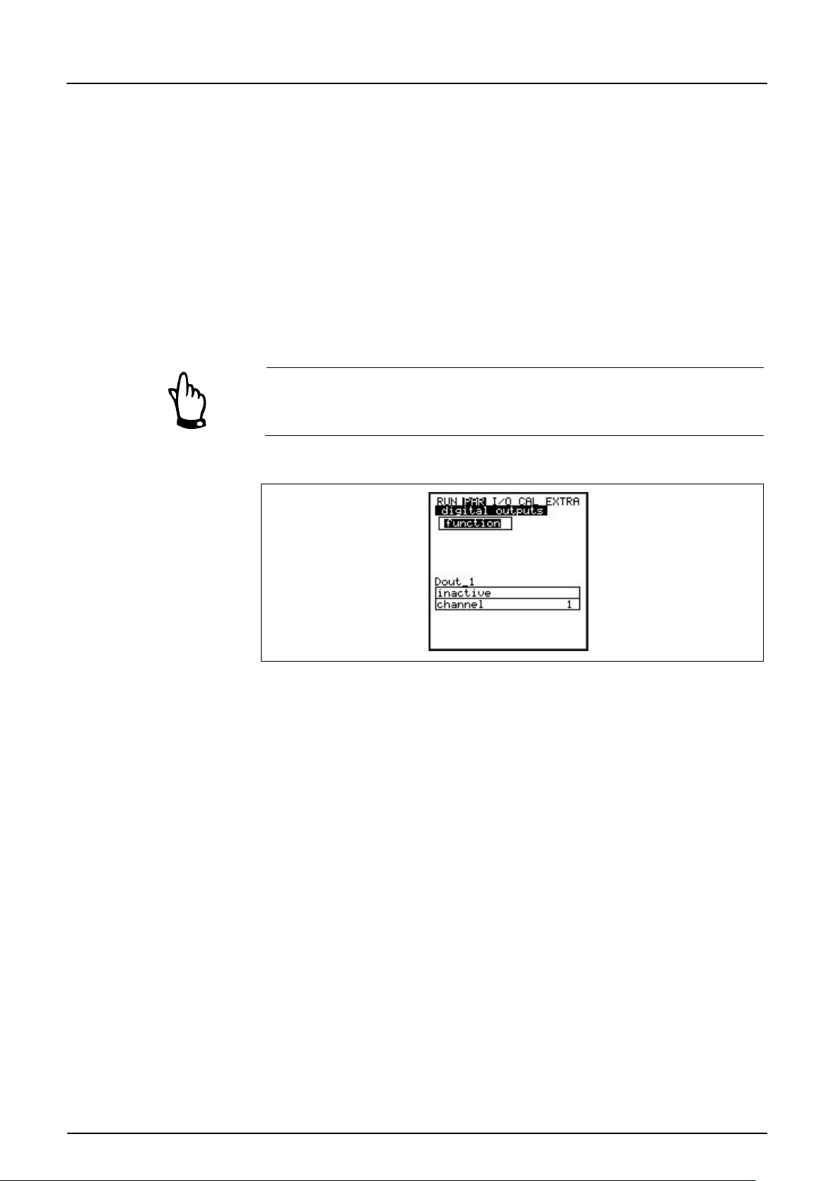
Instruction Manual
PCM F
PCM F - Rev. 00 as of 24.10.2007 Page 79
Function
One of the following functions is going to be assigned to the relay which has
Name
This menu can be viewed only as soon as a function has been enabled. “Name”
Example:
A measurement place is partly tending to backwater formation and the negative
value is to be detected as well. This case requires the output signal to be set
"floating”.
This means that flow = 0 will output a V signal in the middle of the measurement
span.
Example:
0 V = -100 l/s
10 V = 100 l/s
In this case flow = 0 yields 5 V as output. Backwater will cause the analog signal
to decrease, positive flow will cause it to increase.
The analog output will be updated during a measurement cycle. Between two
measurement cycles (PCM F in “sleep mode“) the voltage value will be held
using the latest value.
8.5.7 Parameter Menu “Digital Outputs“
Fig. 8-42 Submenu digital outputs
This menu allows to define functions as well as accompanying parameters such
as limit values, impulse duration and more of distinct digital outputs.
been chosen by selecting the channel number:
- disabled
- limit contact flow (relay will energise if the value exceeds a certain flow
threshold and will de-energise if the value falls below a second threshold).
- limit contact velocity (relay will energise if the value exceeds a certain
velocity threshold and will de-energise if the value falls below a second
threshold).
- limit contact level/height (relay will energise if the value exceeds a certain
level threshold and will de-energise if the value falls below a second
threshold).
- pos-total impulse
- sampler
means the name of the relay output. It is not necessary however to input a
name as it currently is for device-internal use only.
Set the name as described under >PAR/Measurement place/Name of
measurement place<.
Page 79
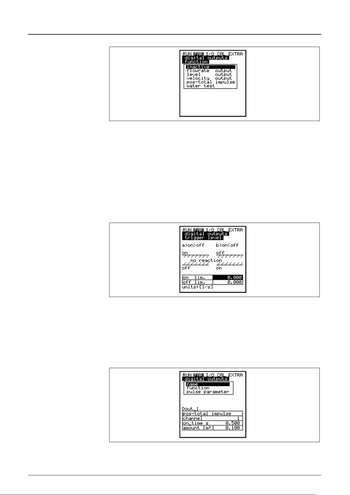
Instruction Manual
PCM F
Page 80 PCM F - Rev. 00 as of 24.10.2007
Logic
Select between >normally open< and >normally closed< by using the >ALT <
Trigger level
This menu can be viewed only as soon as the function >Limit contact< has been
Pos-Total Impulse
This menu is visible only if >Pos-Total impulse< has been selected as function.
Fig. 8-43 Defining functions
key.
Choosing >normally open< will cause the relay to energise as soon as the
threshold set has been reached, choosing >normally closed< will cause the
relay to energise immediately after the parameters have been set and to deenergise as soon as the according threshold has bee reached.
enabled.
Fig. 8-44 Threshold settings
The switching behaviour depends if the switch-on point is set higher or lower
than the switch-off point: threshold behaviour (ON>OFF) or as in-bounds alarm
(ON<OFF).
Fig. 8-45 Setting impulse parameters
Page 80
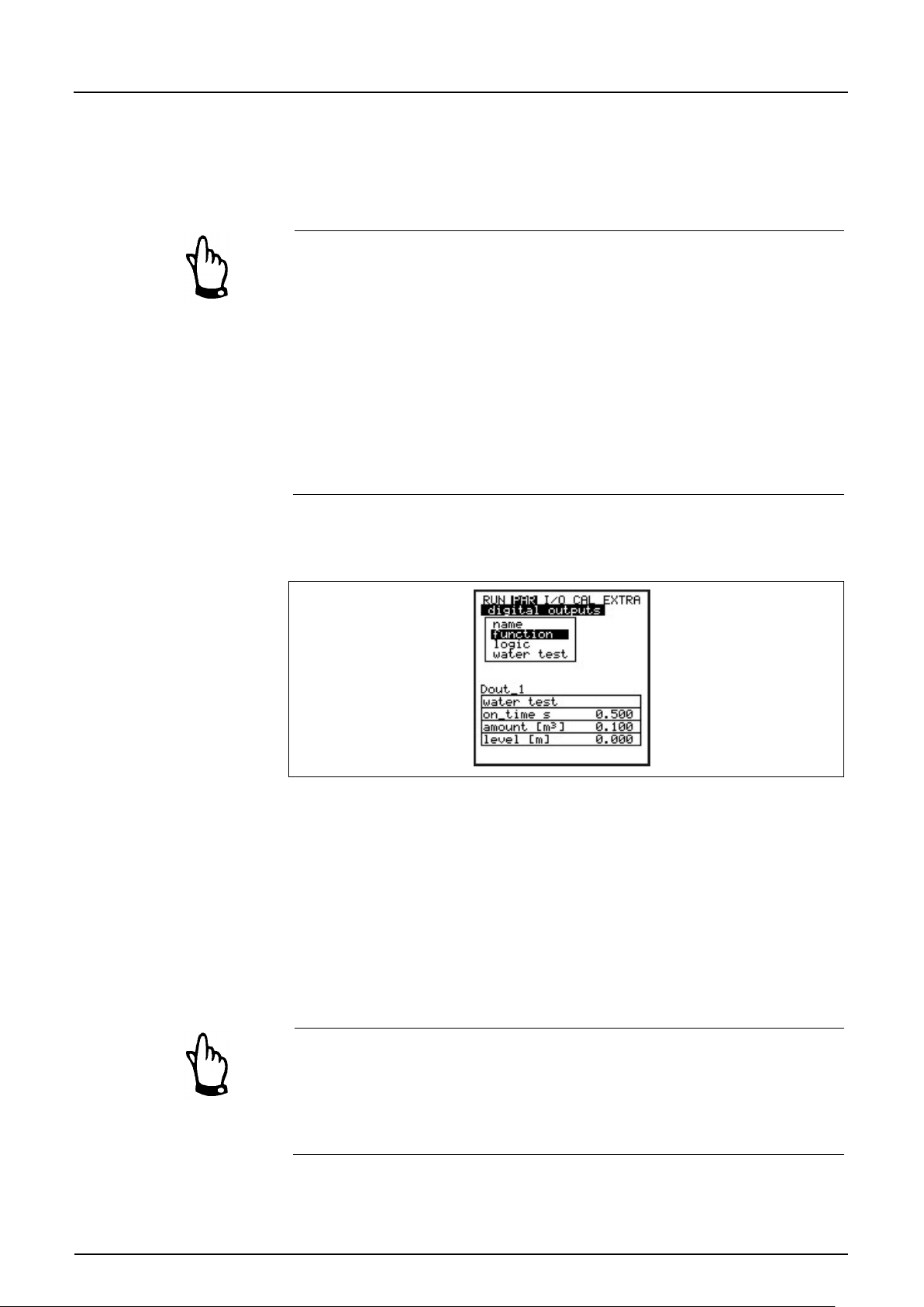
Instruction Manual
PCM F
PCM F - Rev. 00 as of 24.10.2007 Page 81
Duration s
Enter the impulse duration here and adjust the value to the impulse counter
Volume [m³]
If this volume has been reached the contact will be closed for the duration set.
Sampling
This menu can be viewed only as soon as the function >water test< has been
Duration s
Set impulse duration here. Adjust the setting depending on the sampler used.
Volume [m³]
The contact will close for the duration set as soon as this volume has been
Level [m]
This parameter is to protect the connected sampler. The contact will be closed
used.
The PCM F has been programmed to immediately process the impulses which
have been cumulated within the memory cycle. The unit will switch over to
permanent mode until the impulses have been processed if the measurement
time is not sufficient.
Due to this reason it is important to adjust the number of impulses to the
expected maximum volume.
Example:
measurement cycle = 5 min., duration = 0.5 s, volume 1 m³,
measured flow rate = 100 l/s
5 min x 60 s x 100 l/s / 1000 = 300 impulses x 0.5 s = 150 s
The PCM F will operate in permanent mode for the calculated period.
enabled.
Fig. 8-46 Sampling settings
reached.
only if the fill level set has been exceeded. This helps to prevent the sampler
from drawing air.
The PCM F will operate in continuous mode if >Sampling< has been selected
as function. The selected memory cycle now defines only the storage interval
for the memory card. This ensures absolutely precisely timed sampling in case
of reaching the volume set.
In this mode PCM F battery lifetime is approx 3 days.
Page 81
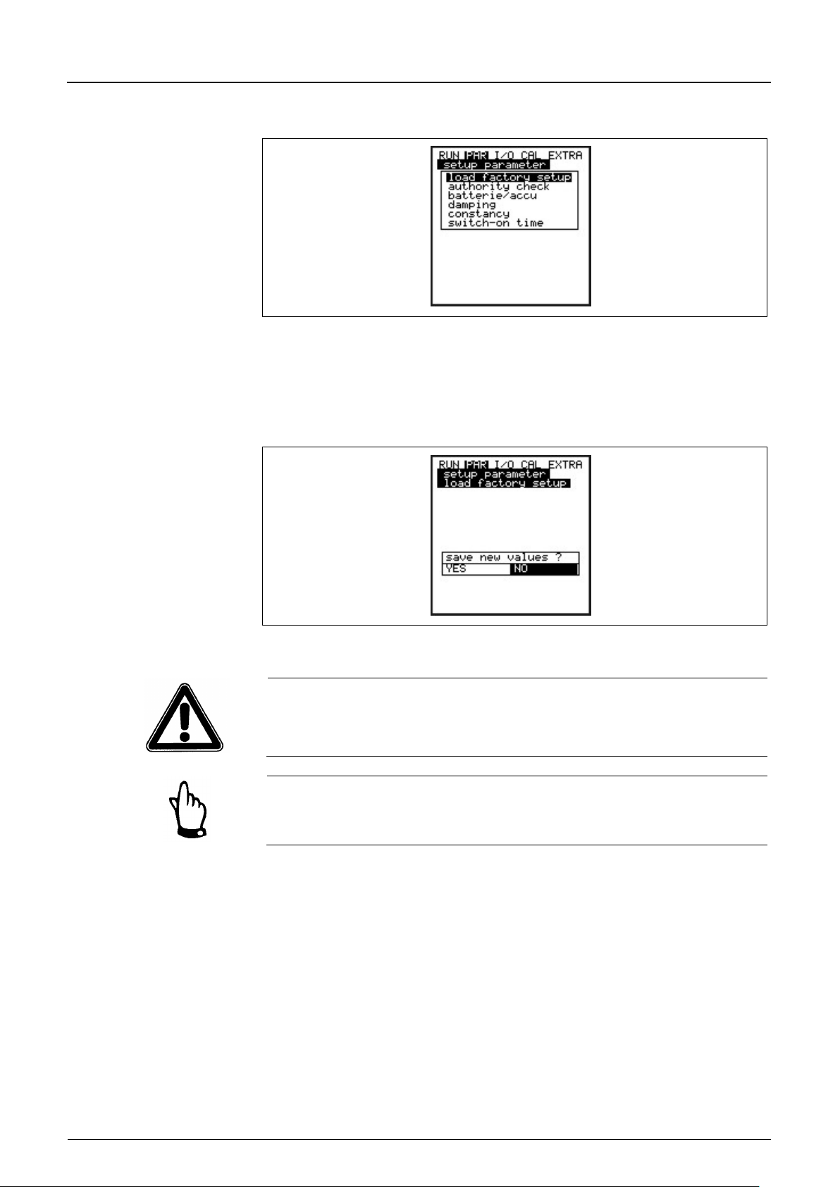
Instruction Manual
Page 82 PCM F - Rev. 00 as of 24.10.2007
Load factory setup
Enables to execute a general reset. The following screen appears:
Service code
Additional system setting options are going to be revealed as soon as a special
Battery / rechargeable
Enter the maximum capacity of the used power source here. This value will be
Damping
This menu enables to adjust the display and analog output damping between
8.5.8 Parameter Menu “Setup Parameter“
Fig. 8-47 Submenu settings
This menu allows to modify or to restore the basic system settings described
below.
PCM F
Fig. 8-48 Executing a general reset
Selecting “YES“ will reset the system to the default parameter settings. The
default parameters will be loaded and all customer settings will be reset
(general reset of system).
In order to avoid faulty programming it is required to execute a general system
reset prior to each initial start-up.
code has been entered. It is possible to modify e.g. beam angle or medium
sound velocity, transmit voltages or special adjustments regarding the
transmitter crystal drive. These settings are reserved to used by the NIVUS
initial start-up service as these modifications require comprehensive expert
knowledge and do not need to be adjusted during standard use.
used as a basis to calculate the remaining capacity and more.
20 and 600 seconds.
Page 82

Instruction Manual
PCM F
PCM F - Rev. 00 as of 24.10.2007 Page 83
Stability
This parameter is going to „stabilise“ the readings for the time set in case of
Max. Measurement
The PCM F automatically controls the required measurement time depending
Example 1:
damping 30 seconds, jump from 0 l/s to 100 l/s (=100 %) – the unit requires
30 seconds to run from 0 l/s to 100 l/s.
Example 2:
damping 30 seconds, jump from 80 l/s to 100 l/s (=20 %) – the unit requires
6 seconds to run from 80 l/s to 100 l/s.
measurement dropouts which might be caused by e.g. hydraulic interferences.
The parameters damping and stability will take no longer effect as soon as the
unit is going to switch over to active memory mode. Due to the short
measurement duration in this mode the unit will use the internally stored
damping and stability period of 0 seconds.
time
on several parameters. This parameter can be used to influence the
automatism, which however is not recommended to be carried out without the
aid of a NIVUS technician.
8.5.9 Parameter Menu "Storage Mode “
The PCM F allows to save recorded data regarding flow velocity, level,
temperature and flow rates as well as input and output signal readings on
compact flash card.
You can use NIVUS compact flash cards with capacities from 4 to 128 MB.
These cards can be purchased from your NIVUS representative if required.
Use memory cards purchased from NIVUS only. Other manufacturer’s cards
may lead to irreversible loss of data or measurement failure (e.g. permanent
transmitter reset).
NIVUS is not going to assume any liability due to data loss resulting from the
use of third party memory cards.
The enabled memory mode will be indicated by an icon in RUN menu (see also
chapter 7.3).
The PCM F will fall to energy-saving standby mode three minutes after the last
key action, i.e. the unit is only going to turn on following the intervals set. The
PCM F display is disabled when in memory mode (see also chapter 7.5.1)
Page 83
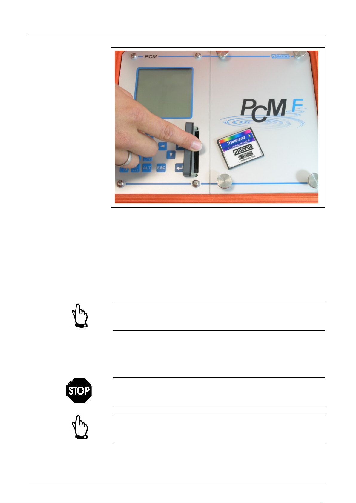
Instruction Manual
PCM F
Page 84 PCM F - Rev. 00 as of 24.10.2007
Fig. 8-49 Memory card slot
Due to the card’s technically restricted number of storage cycles (approx.
100.000 writing events), the PCM F does not constantly save upcoming data on
card. This is to protect the card. First of all the measurement data are saved in
an internal memory. Then the readings are going to be transmitted to memory
card once per hour. Activating the PCM F (by pressing any key) or by pressing
the >ALT< key if the unit is active will immediately execute data transmission to
memory card which will be indicated on the display by the message „Memory
card busy“. The interval is pre-set by the internal system time.
Transmit data to compact flash card prior to card replacement as described
above to make sure all data being saved on memory card.
Data sets are going to be saved in ASCII format creating a file with the name of
the respective measurement place set. The suffix is >.txt<.
The data sets can be read and edited using common software with ASCII
interface such as EXCEL.
Never format memory cards on PC but always on PCM F. The PCM F is not
capable of using formats created by PC and therefore does not accept cards
formatted on PC.
Data will always be saved as current values at the moment of saving.
Page 84
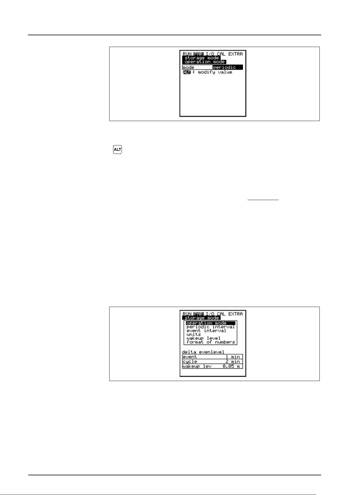
Instruction Manual
PCM F
PCM F - Rev. 00 as of 24.10.2007 Page 85
Use this key to toggle between following modes:
disabled
= no data saving
periodic
= periodic saving of flow readings and
Event
= The PCM F is able to toggle between two saving cycles.
Level
This setting will force the sensor-integrated electronics to
Digital I1
The PCM F is permanently monitoring the digit al inp ut. T he
Periodic Interval
This parameter is to define the saving interval. Set a value between 1 and
Mode
Source
Fig. 8-50 Selecting memory options
peripheral input signals
Switchover will be carried out immediately as soon as a
level-dependent threshold has been exceeded or by
receiving a respective impulse from the digital input.
retrieve fill level data every 5 seconds. The PCM F will be
activated immediately in case of exceeding the threshold,
switching over to event mode.
unit will switch over to event mode immediately as soon as
the digital input is going to be enabled.
Fig. 8-51 Memory mode screen
60 minutes.
There are only exact fractional amounts of 1 hour allowed to be set (1 min.;
2 min.; 3 min.; 4 min.; 5 min.; 6 min.; 10 min.; 15 min.; 20 min.; 30 min. or
60 min.).
Page 85
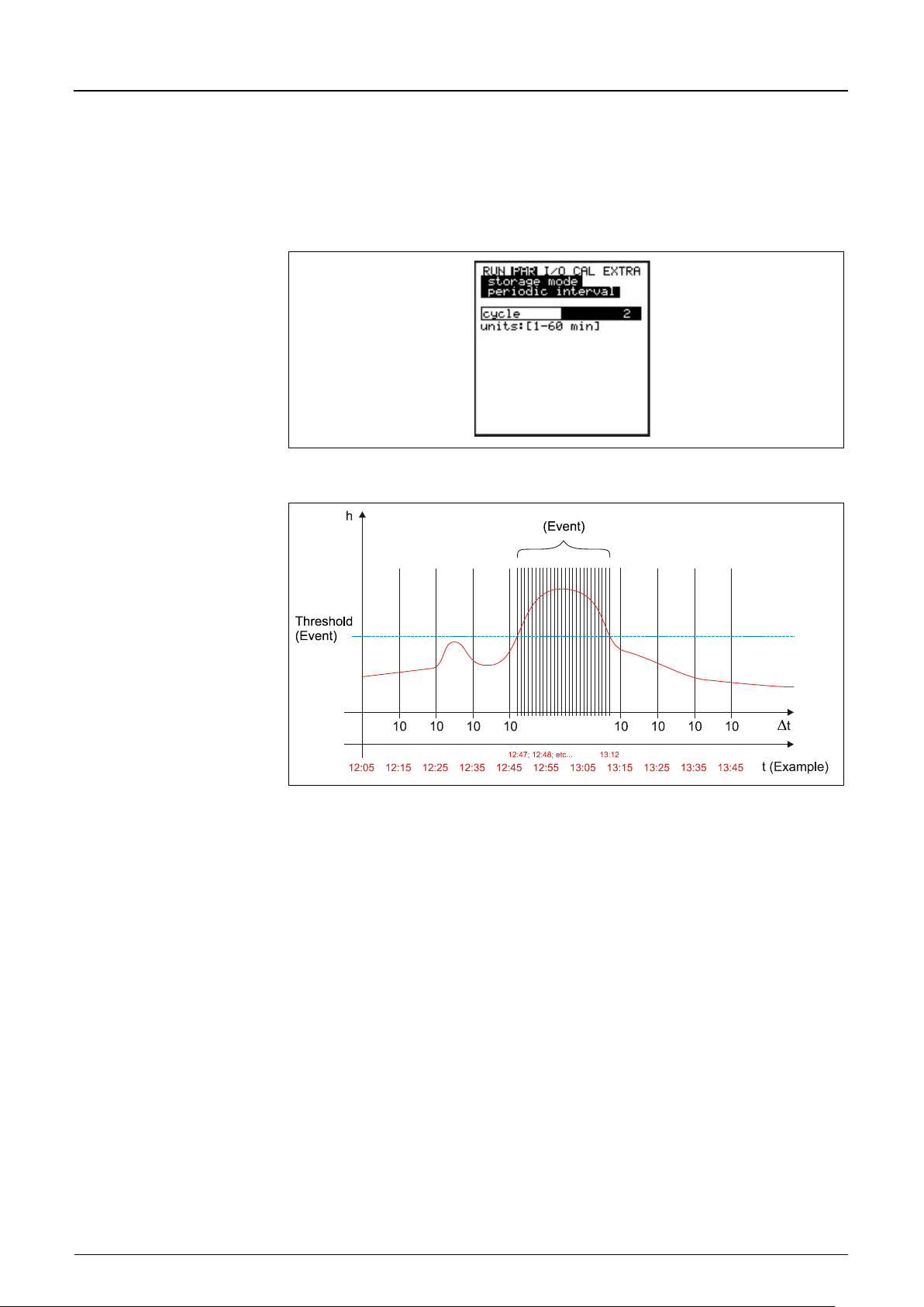
Instruction Manual
PCM F
Page 86 PCM F - Rev. 00 as of 24.10.2007
Event interval
This parameter is active if the event mode has been enabled and is to define
min.; 10 min.; 15 min.; 20 min.;
Units
Define which units are to be used to save the 3 main parameters flow, level and
the saving cycle in case of events occurring. It is possible to set values between
1 minute and 1 hour. There are only exact fractional amounts of 1 hour allowed
to be set (1 min.; 2 min.; 3 min.; 4 min.; 5 min.; 6
30 min. or 60 min.).
Fig. 8-52 Setting the saving cycle
Fig. 8-53 Event parameter setting example
velocity. Select from metric (e.g. litres, cubic metres, cm/s and more), English
(ft, in, gal/s, and more.) or American system (fps, mgd and more). After your
selection has been confirmed the display will jump to the next screen
automatically.
When it comes to be saved on memory card, it is possible to define a unit for
each of the measured and calculated flow, velocity and fill level readings. These
settings do not have an effect on the display. There are various units available
depending on the selection made previously.
Page 86
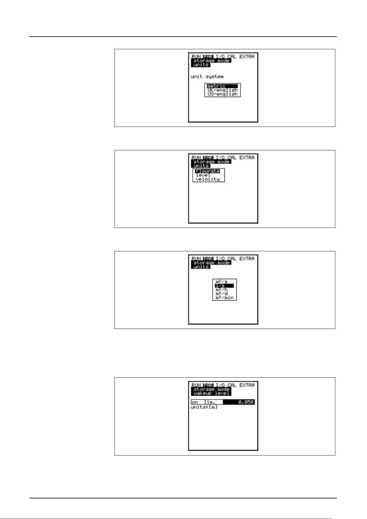
Instruction Manual
PCM F
PCM F - Rev. 00 as of 24.10.2007 Page 87
Wakeup level
This menu is to define the fill level which is used to switch over from periodic
Format of numbers
Choose between commas or dots to be used as decimal points.
Fig. 8-54 Selecting the unit system
Fig. 8-55 Selecting the measurement value
Fig. 8-56 Selecting the units
interval to event interval.
Fig. 8-57 Wakeup level screen
Page 87
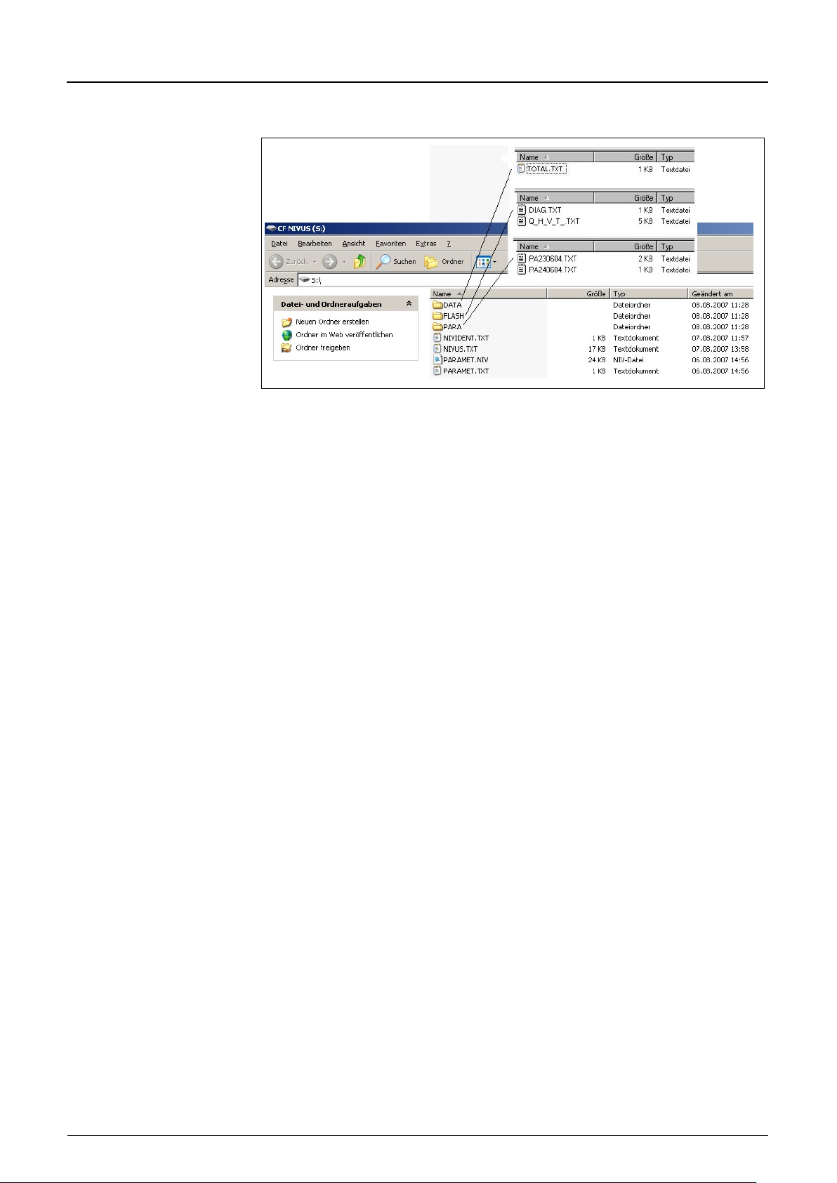
Instruction Manual
Page 88 PCM F - Rev. 00 as of 24.10.2007
DATA
Day totals are saved in the data file >TOTAL.TXT< in this folder. Save by using
Flash
This is the folder where the backup file is being saved (to execute select I/0 –
PARA
This folder includes all parameter files with a date stamp.
NIVIDENT
The name of the measurement place. If the name of the measurement place
Name of Measure-
This is the file where the measurement values are saved. It is going to be saved
PARAMET.NIV
These files are created as soon as parameters are being saved on the memory
8.5.9.1 Data Structure on Memory Card
Fig. 8-58 Data structure on memory card
the menu points I/O / Memory card / Day totals (see chapter 8.6.6).
PCM F
Memory Card – Save backup).
The name of the saved file is always >Q_H_V_T.TXT<. It contains the internal
memory values on level, velocity, flow and temperature.
The file >DIAG.TXT< contains all messages including error messages which
might have been occurred during measurement operation. These might be start
and end of Internet communication, modem restart, CPU restart after system
reset or after reprogramming.
The respective message is labelled with date and time:
>: received error/message
<: reason of error/message cleared
The content of this folder allows to retrace transmitter settings regarding the
measurement place as well as parameter settings which might have been
modified. The latest modification within the course of a day will be saved in a
file named PA TT MM JJ .TXT (TT = day, MM = month; JJ = year).
saved on card does not comply with the name of the measurement place saved
in the PCM F, the unit will prompt to format the card. The PCM F will not save
any data as long as the card has not been formatted.
ment Place.TXT
using the name of the measurement place set.
PARAMET.TXT
card. The file PARAMET.NIV is required in order to upload data to the PCM F.
PARAMET.TXT is the print version of PARAMET.NIV as text file (only
parameters modified before are going to be exported).
Page 88
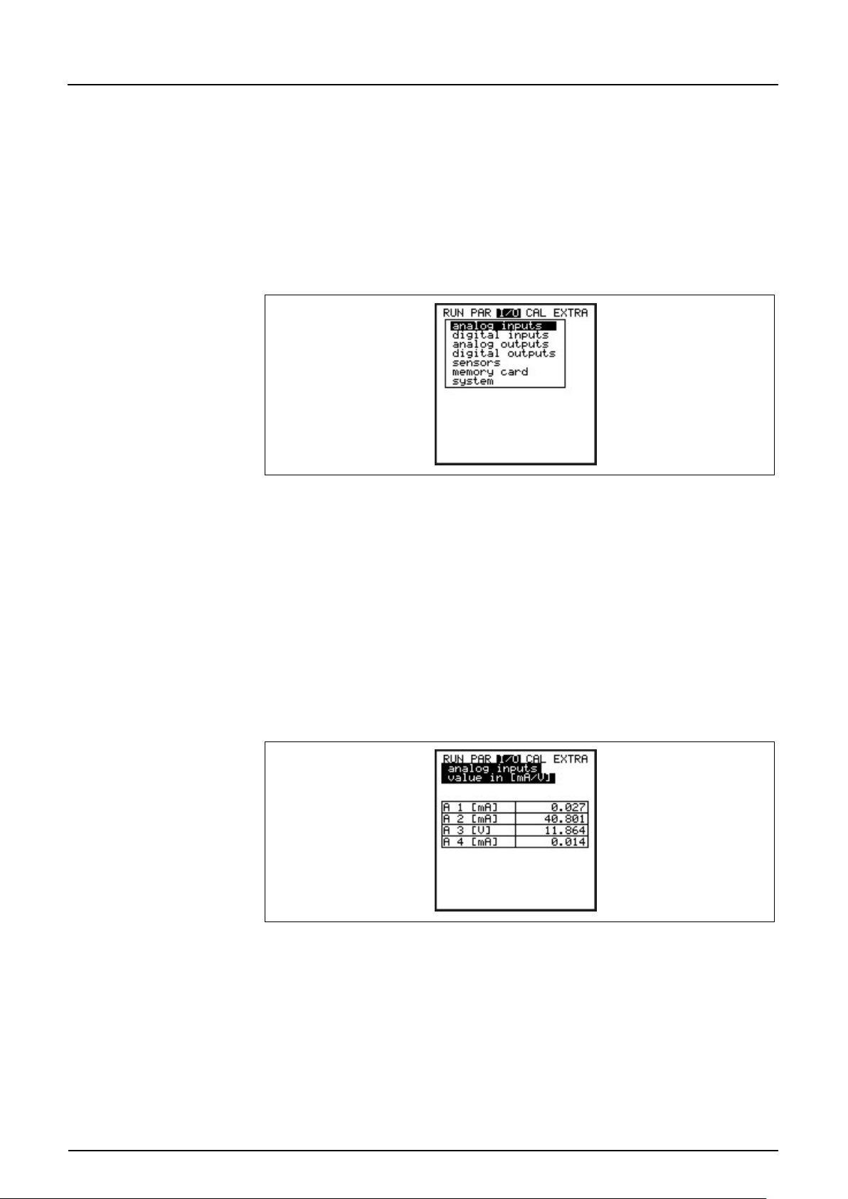
Instruction Manual
PCM F
PCM F - Rev. 00 as of 24.10.2007 Page 89
A 1 [mA]
Input signal from socket 3.
A 2 [mA]
Indicates the current power consumption of transmitter and connected sensors.
A 3 [V]
Current battery voltage.
A 4 [mA]
Indicates the input current for the mA input from the multifunctional socket.
8.6 Signal Input / Output Menu (I/O)
This menu includes several submenus which both serve to assess and to check
sensors as well as to control signal inputs and outputs. It allows to indicate
various values (current values of inputs and outputs, relay conditions, echo
profiles, individual velocities etc.), however does not enable to influence signals
or conditions (offset, adjustment, simulation or similar). The menu therefore
primarily serves in order to assess the parameter settings and for error
diagnosis.
Fig. 8-59 I/O submenu
8.6.1 I/O Menu “Analog Inputs”
Analog input values routed to the transmitter input clamps can be controlled and
checked here.
Fig. 8-60 mA Inputs
Page 89
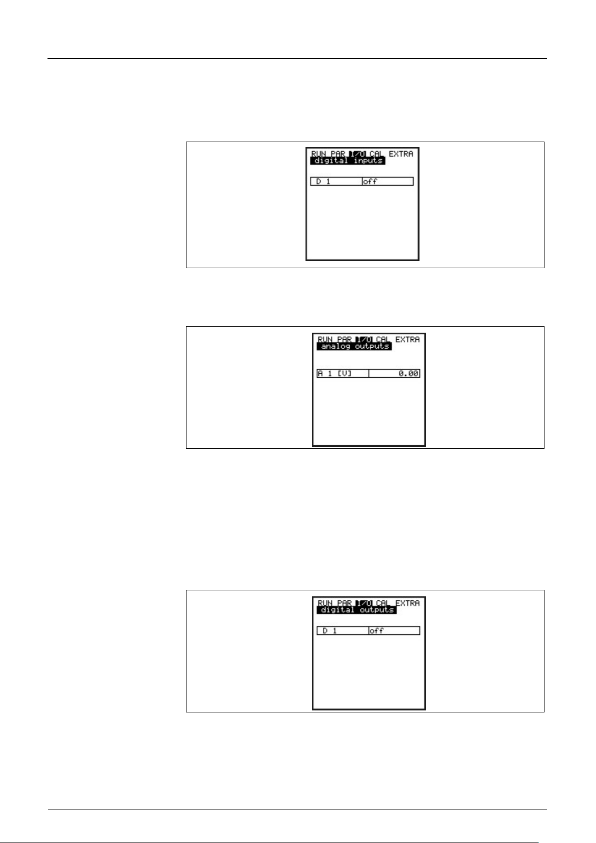
Instruction Manual
Page 90 PCM F - Rev. 00 as of 24.10.2007
8.6.2 I/O Menu “Digital Inputs”
Digital input values routed to the transmitter input clamps can be viewed here.
Reading is either logically "OFF“ or "ON“.
Fig. 8-61 Screen digital values
8.6.3 I/O Menu “Analog Outputs”
PCM F
Fig. 8-62 Screen analog values
This menu is to indicate the calculated value which is to be sent to the analog
converter.
8.6.4 I/O Menu “Digital Outputs”
Conditions which are calculated by the transmitter and routed to the relay for
output purposes subsequently can be viewed here. Reading is either logically
"OFF“ or "ON“.
Fig. 8-63 Screen digital values
Page 90
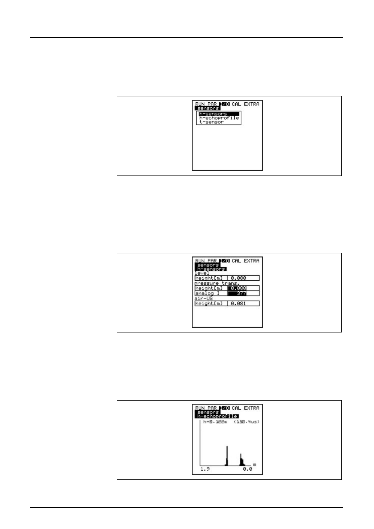
Instruction Manual
PCM F
PCM F - Rev. 00 as of 24.10.2007 Page 91
H Sensor(s)
Indicates the measured fill levels.
H Echo Profile
Enabled only in case of air-ultrasonic level measurement from top down.
8.6.5 I/O Menu “Sensors”
This menu including the respective submenus allow to view and to asses the
most important sensor conditions. It hence provides information on the quality of
the measurement place, echo signal quality and many more parameters.
Fig. 8-64 I/O submenu
There are varying menus depending on the sensor version (level measurement
using pressure, air-ultrasonic or external sensor) used:
Example 1:
Fig. 8-65 Menu with pressure and air-ultrasound
The sensor types are going to be displayed accordingly if only 1 or 2 types have
been selected.
Fig. 8-66 Selecting level measurement echo profile
Page 91
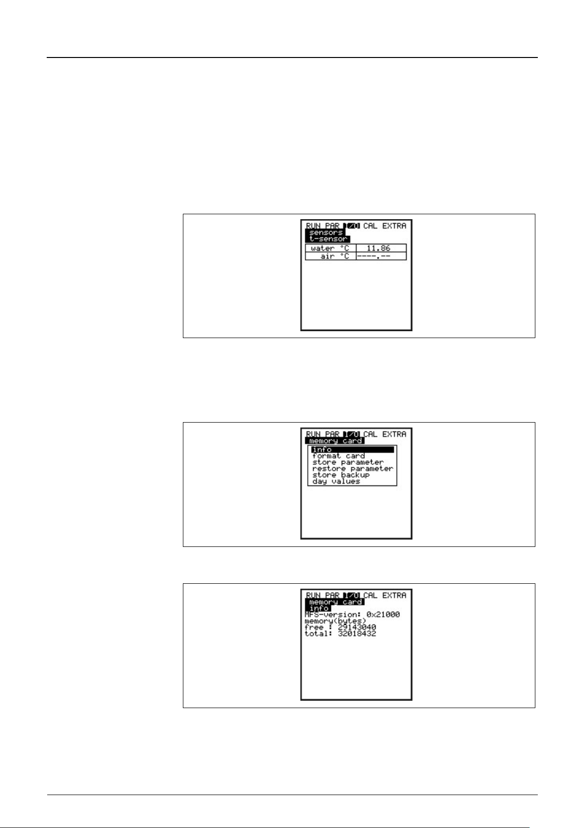
Instruction Manual
PCM F
Page 92 PCM F - Rev. 00 as of 24.10.2007
T Sensor
This screen allows to view the measured water and air temperature (only
This graph allows the service personnel to assess the echo signal in the
measured acoustic path. Ideally the first peak (reflections from the interface
between water and air) is very narrow, steep und high, all further peaks are
smaller and wider.
possible in case of using external air-ultrasonic sensor driven by PCM F).
Invalid values indicate cable break, short circuits or incorrectly clamped
connections.
Fig. 8-67 Temperature screen
8.6.6 I/O Menu “Memory Card”
This menu allows to recall information on the memory card.
Fig. 8-68 Memory card options
Fig. 8-69 Card info me n u
Information can be recalled only if the memory card is plugged. To be able to
indicate the remaining capacity time the card must be plugged into the PCM F
for one hour at least.
Page 92
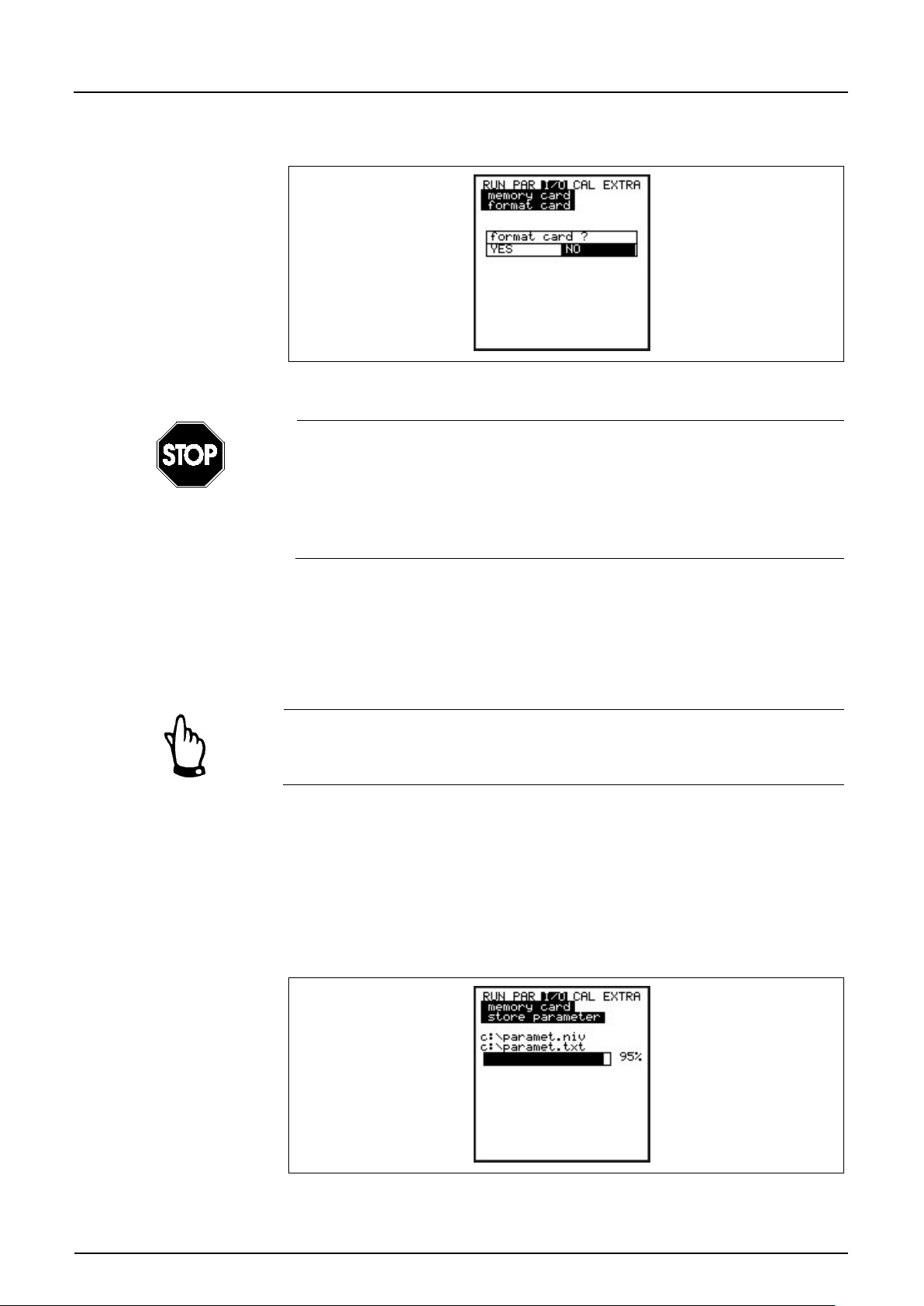
Instruction Manual
PCM F
PCM F - Rev. 00 as of 24.10.2007 Page 93
You can use the >Memory Card< menu to execute card formatting as well.
Fig. 8-70 Format card
Use memory cards purchased from NIVUS only. Other manufacturer’s cards
may lead to irreversible loss of data or measurement failure (e.g. permanent
transmitter reset).
Never format memory cards on PC but always on PCM F. The PCM F is not
capable of using formats created by PC and therefore does not accept cards
formatted on PC.
Formatting the card will erase all data saved on the card.
The card can be replaced at any time by pressing the >ALT< key. This action is
going to transmit all data from the internal memory to the memory card. The
message >Memory card busy< appears.
Do not replace the card as long as the message >Memory card busy< is
indicated on the display.
Furthermore it is possible to read out settings from or to save settings to
the PCM F.
Parameters set will be written to memory card by using the menu point “Save
parameters “. This will take approximately 30 seconds. The progress is going to
be indicated by a progress bar moving from left to right. After transmission has
been finished successfully the display will indicate >OK< and jump back to the
memory card menu subsequently.
Fig. 8-71 Saving parameters on memory card
Page 93
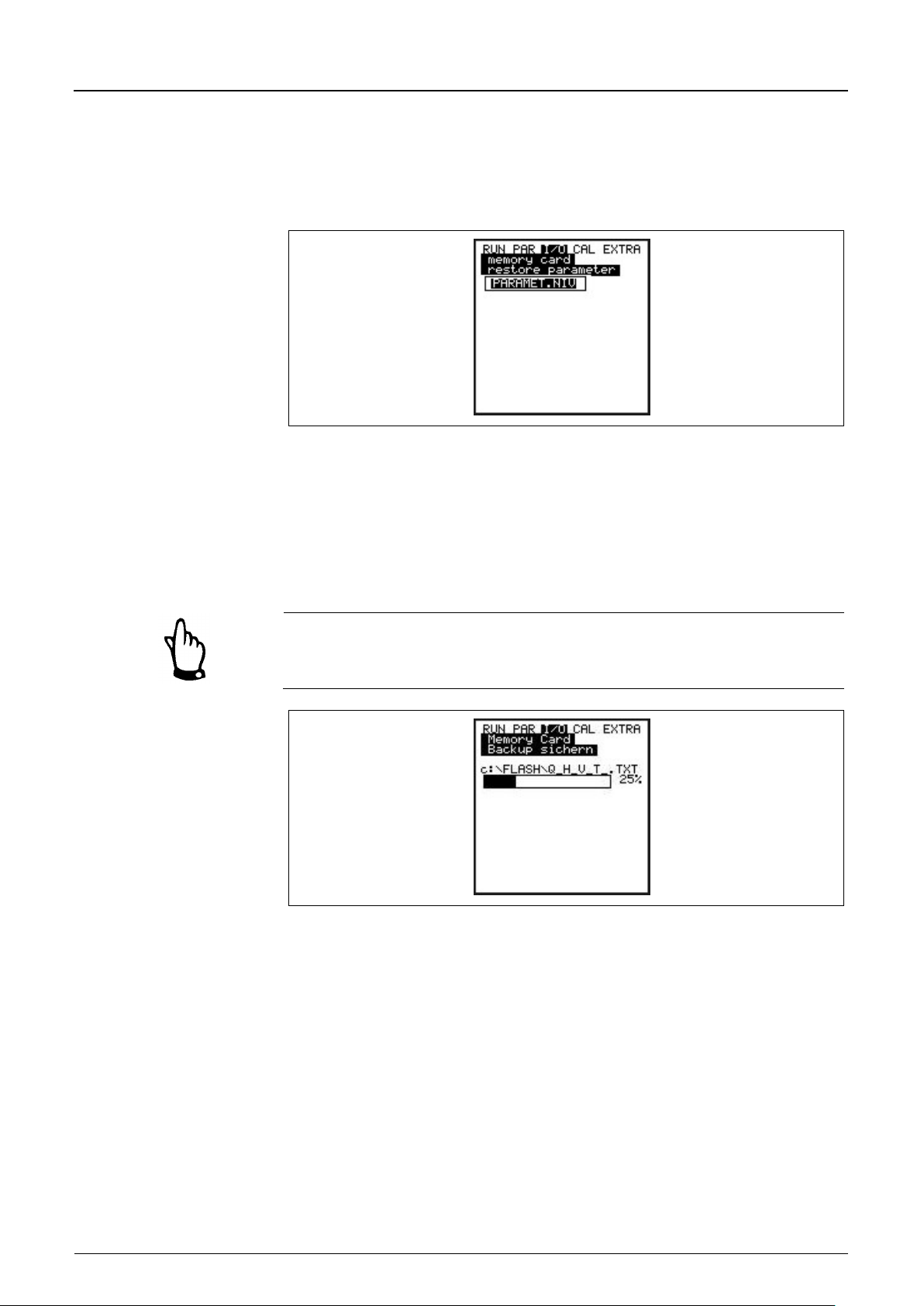
Instruction Manual
PCM F
Page 94 PCM F - Rev. 00 as of 24.10.2007
The menu point „Load parameters“ first of all will show all program files saved on
memory card. The file will be transferred to the PCM F after choosing.
The name of the file required to program the PCM F by memory card is
„PARAMET.NIV“.
Fig. 8-72 Loading parameters from memory card
The PCM F has an additional internal memory which can be saved on memory
card as well (save backup). This circular buffer has a capacity of approx. 20.000
measurement values which allows to record the parameters >Level, velocity,
flow and temperature< for a period of 14 days.
In order to indicate trends in RUN menu, data from the internal memory is going
to be used furthermore.
Executing a system reset will erase all data from the internal memory.
Fig. 8-73 Save backup
It is possible to save a maximum of 90 day totals on compact flash card. The
data will be saved in the „Data“ folder using the name >Total.txt< including date,
time and total (difference to previous day). The totalising time refers to the
settings in “RUN / Day totals / Cycle“ (see Fig. 8-7).
The circular memory always indicates the past 90 days.
Page 94
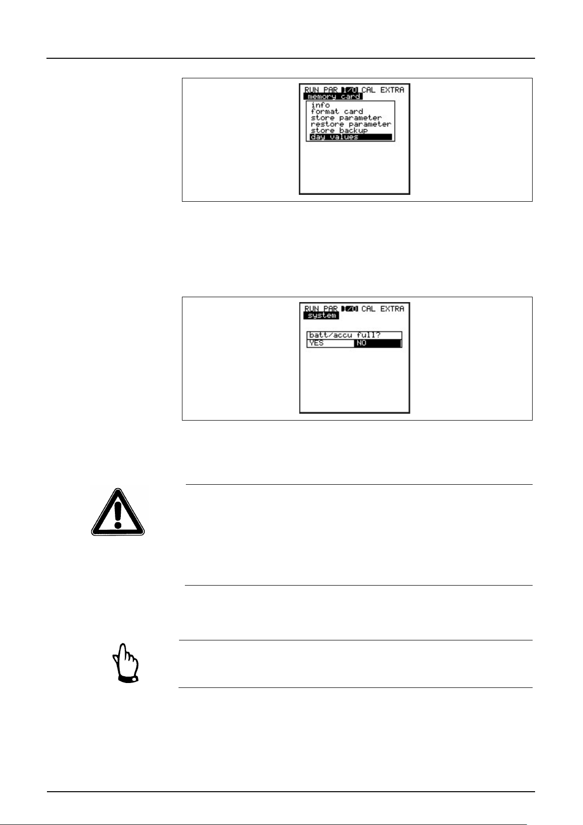
Instruction Manual
PCM F
PCM F - Rev. 00 as of 24.10.2007 Page 95
8.6.7 I/O Menu „System”
Fig. 8-74 Save day totals
This menu allows to recall information on the battery. It also serves to
recalculate the capacity of the rechargeable battery after it has been replaced.
Fig. 8-75 System menu
Confirming this message with >YES< will reset the capacity to 100% and the
PCM F is going to recalculate the battery lifetime.
The indicated lifetime bargraph with % indication is the result of a calculation
assuming the maximum capacity and the power consumption. To achieve
accurate results please observe to always use a completely charged battery.
This reading shall be considered as a typical value due to the system-inherent
lifetime of rechargeable batteries.
In order to avoid total discharge and data loss replace the rechargeable
battery if the voltage drops below 11 V during standard operation.
Confirmation with >NO< will retain the current values which is useful to recall
information on the remaining battery lifetime.
Always confirm with >YES< after replacing the rechargeable battery by a
new one.
Page 95
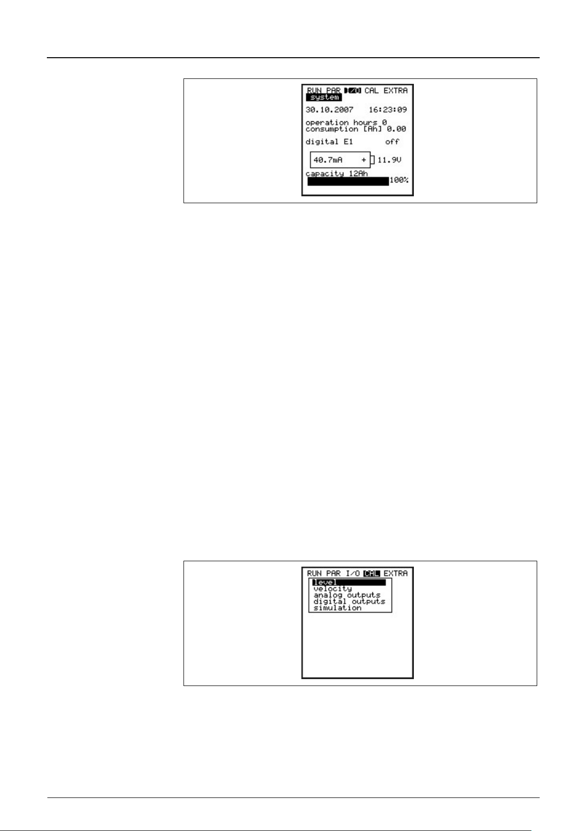
Instruction Manual
PCM F
Page 96 PCM F - Rev. 00 as of 24.10.2007
Date and Time
current date and time.
Operating Hours
number of PCM F operating (measuring) hours. Does not count
Consumption [Ah]
power consumption during operating hours in Ah.
Digital I1
condition of digital input.
Power Consumption
current power consumption and current battery voltage.
Capacity
maximum capacity of rechargeable battery. Enter this value under >PAR-
Fig. 8-76 Battery lifetime screen
standby periods.
Due to battery protection purposes sensors will be switched off if voltage
reaches 11.0 V (error message: error sensor 1).
Settings-Battery<. Percentage provides insight into remaining battery lifetime.
8.7 Calibration and Calculation Menu (CAL)
Adapt analog outputs to the following system in this menu by emulating relay
switching events and analog outputs.
Additionally it is possible to calibrate the fill level sensors by using a reference
value.
Fig. 8-77 Selection menu
Page 96
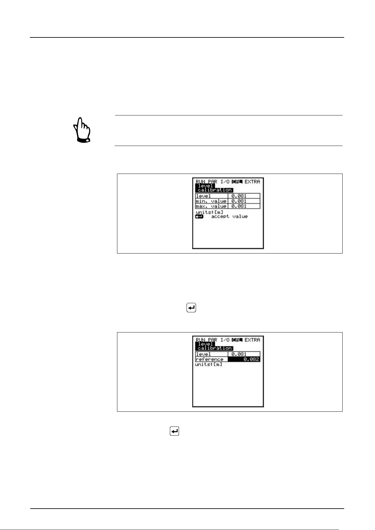
Instruction Manual
PCM F
PCM F - Rev. 00 as of 24.10.2007 Page 97
8.7.1 Cal Menu “Level“
This submenu enables to calibrate the level sensors used e.g. in order to
compensate a level offset due to constructional conditions.
Calibration is carried out by entering a reference value. This reference value has
been determined by an independent measurement such as by using a precision
ruler.
All active sensors are going to be adjusted to this reference value.
The following screen will come up after the calibration prompt has been confirmed:
Fig. 8-78 Level screen
The currently enabled fill level sensor as well as its fluctuation range including
min. and max. values will be displayed. This allows to draw conclusions on the
prevailing flow level conditions (e.g. waviness of surface).
Best results can be achieved at low fluctuation range. Accepting the current level
reading by pressing the
reference value. Input this value in the screen below.
Fig. 8-79 Entering th e reference value
key requires to investigate an accom pan ying
Confirmation with
active level sensors. This overview is a comparison between the previous
(current) and the new (new) offset.
The PCM F will output an error message if the deviation between both values is
too high. The adjustment will not be accepted.
In this case repeat the adjustment procedure and if required check the
conditions of installation.
is going to bring up an overview screen displaying all
Page 97
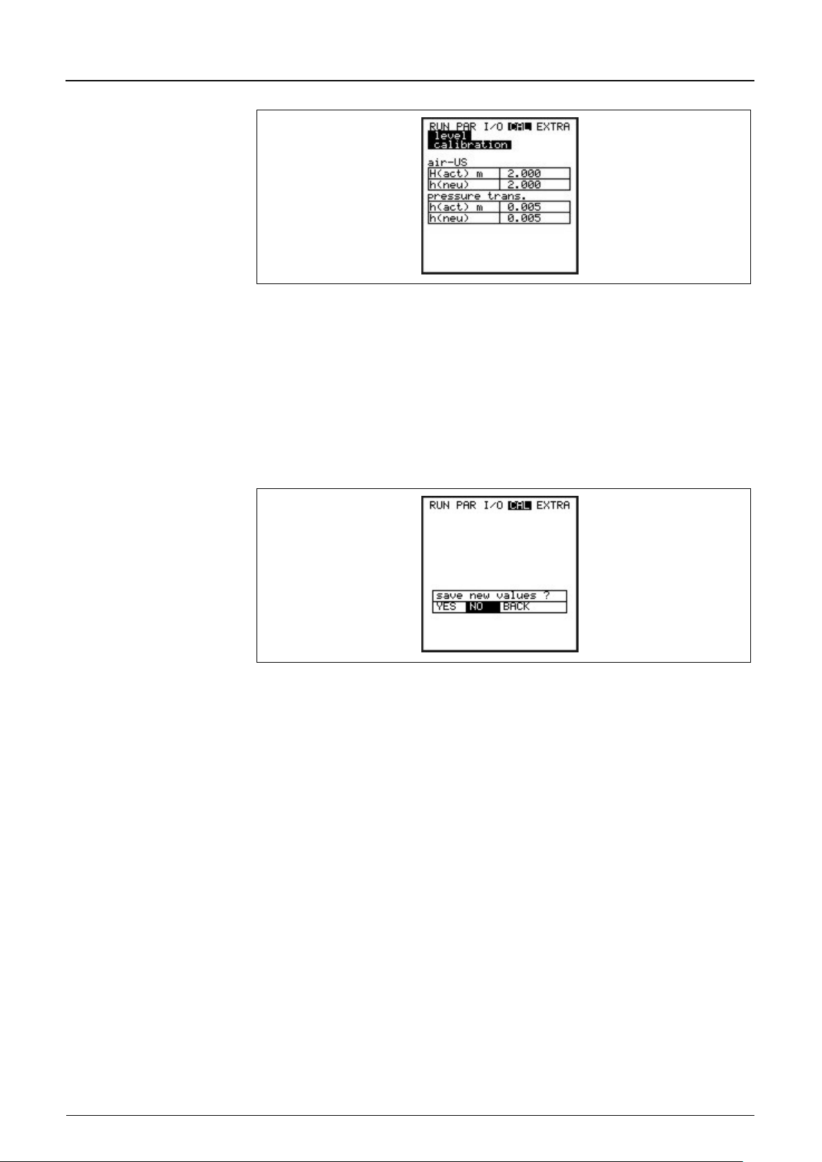
Instruction Manual
PCM F
Page 98 PCM F - Rev. 00 as of 24.10.2007
Fig. 8-80 Adjustment screen
Executing an adjustment will adapt the installation height of the single sensors in
PAR / Level menu accordingly. Hence it is required to confirm the prompt >Save
values?< with >YES< before leaving the menu. This action will cause the
adjustment values to be accepted.
Entering >NO< will abort the adjustment procedure.
Choosing >BACK< will take you back to the start of the procedure without
accepting modified values.
Fig. 8-81 Saving values
Page 98
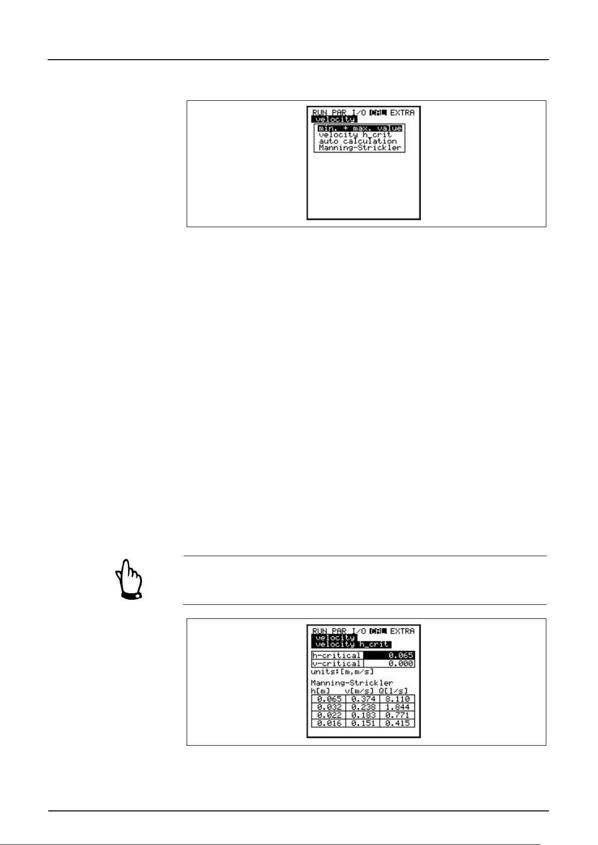
Instruction Manual
PCM F
PCM F - Rev. 00 as of 24.10.2007 Page 99
min. + max. Value
Defines the flow velocity measurement range.
Geschw. h_krit
This parameter includes required data to calculate a Q/h relation below the level
8.7.2 Cal Menu "Velocity“
Fig. 8-82 Flow velocity screen
h_crit. The level h_crit is pre-determined by the construction of the sensor as
well as the measurement method and is set to 0.065 m (2.56 in) per default.
The table either indicates the latest associated values which have been
determined immediately before h_crit has been reached (measured level and
associated velocity) or according values are going to be set here.
The bottom area of the screen shows a table containing theoretical flow values
depending on the parameters set in "Manning - Strickler“ menu and on channel
shape. These values can be used for flow calculation e.g. in case of initial startup with fill levels below h_crit. Modif y table ranges b y entering a level va lu e in
the h_crit line and press >Enter<.
It is possible to use the indicated flow reading to assess the expected flow if
h_crit has been set to current or expected fill level. The accuracy of this value
applies only within the bounds of the Manning - Strickler law.
At the subsequent measuring event the values set are either going to be verified
or corrected if required (automatic YES) or otherwise these values are going to
be used permanently (automatic NO) depending on the setting chosen in the
following menu.
After successfully assessing flow readings it is necessary to reset the parameter
h_krit to be adjusted to the respective application.
Fig. 8-83 Table of values for automatic Q/h relation
Page 99
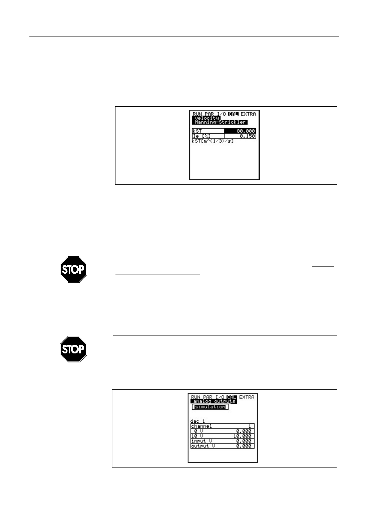
Instruction Manual
PCM F
Page 100 PCM F - Rev. 00 as of 24.10.2007
Auto Calculation
The auto calculation described above can be either enabled or disabled by
Manning-Strickler
This menu is to enter data as calculation basis.
kst
Enter the Manning - Strickler coefficient
Ie [%]
Enter the slope at measurement point in %
Analog Outputs
This parameter allows to simulate the PCM F output signals.
pressing >ALT<.
If enabled please observe that the system shall be free of backwater at lowest
fill levels (risk of backwater formation = no measuring in gravity line required).
Fig. 8-84 Data entry menu
See table Table “Manning - Strickler Coefficients“ in Chapter 14
Basic Hints on Simulation:
The simulation of PCM F outputs will access any following facility areas without
any safety locking measures!
This is the reason why it is required to input the code before accessing these
parameters.
The simulation of analog inputs and outputs is allowed to be carried out by
specialist electricians only which have sound knowledge on the control system
of the facility. This requires detailed preparation. It is absolutely necessary to
have a safety person available!
NIVUS herewith refuse in advance to be responsible for any possible damage
to persons or objects at any extent due to the extremely high risk of danger and
unforeseeable consequences in case of incorrect or faulty simulation!
Fig. 8-85 Overview
Page 100
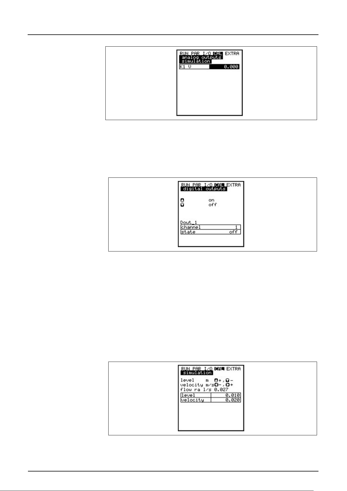
Instruction Manual
PCM F
PCM F - Rev. 00 as of 24.10.2007 Page 101
Simulation
Enter the desired value in Volt and confirm with Enter in order to direct l y output it
Digital Outputs
The arrow keys >up< or >down< will either directly enable or disable the relay.
Simulation
This function allows to simulate a theoretical flow by entering supposed level
Fig. 8-86 Entering th e output value
on the according clamp.
Fig. 8-87 Relay simulation
and velocity values without having these values actually available. The PCM F is
going to calculate the current flow value by using the simulated values based on
the channel dimensions set. The results are going to be sent to the respective
outputs (analog + digital).
Simulate the desired flow velocity by pressing the >left< or >right< arrow keys.
Using the >up< or >down< keys will simulate the desired flow level.
Both values simulated are going to be indicated in the table. The calculated flow
value can be seen above the table.
Fig. 8-88 Flow measurement simulation
 Loading...