

Page 1

80200INS01
September 2000
Hardware Manual
9/8/00
1. Installation
Basics
2. Extension and
Trunk Cabling
3. Connecting
Extensions and Trunks
4. Optional
Equipment
5. Maintenance
Options and SMDR
6. Specifications
and Parts
Page 2

This manual has been developed by Nitsuko America. It is intended for the use of its customers and service
personnel, and should be read in its entirety before attempting to install or program the system. Any comments or suggestions for improving this manual would be appreciated. Forward your remarks to:
Nitsuko America, Telecom Division
4 Forest Parkway
Shelton, CT 06484
Attention: Manager, Technical Publications
Nothing contained in this guide shall be deemed to be, and this guide does not constitute, a warranty of, or
representation with respect to, any of the equipment covered. This guide is subject to change without notice
and Nitsuko America has no obligation to provide any updates or corrections to this guide. Further, Nitsuko
America also reserves the right, without prior notice, to make changes in equipment design or components as
it deems appropriate. No representation is made that this guide is complete or accurate in all respects and
Nitsuko America shall not be liable for any errors or omissions. In no event shall Nitsuko America be liable
for any incidental or consequential damages in connection with the use of this guide.
©2000 by Nitsuko America. All Rights Reserved
Printed in U.S.A.
Page 3

Section 1, INSTALLATION BASICS
In this section . . . Page
Installing the Cabinet . . . . . . . . . . . . . . . . .1-3
Unpacking . . . . . . . . . . . . . . . . . . . . . . . . . . . 1-3
Before Installing. . . . . . . . . . . . . . . . . . . . . . . 1-3
Site Requirements. . . . . . . . . . . . . . . . . . . . . . 1-3
System Configuration . . . . . . . . . . . . . . . . .1-4
System Configuration. . . . . . . . . . . . . . . . . . . 1-4
System Load Factor Calculations . . . . . . . . . . 1-4
Installing the Cabinet . . . . . . . . . . . . . . . . .1-5
Planning the Installation . . . . . . . . . . . . . . . . . 1-5
Removing the Cover . . . . . . . . . . . . . . . . . . . . 1-6
Hanging the Cabinet. . . . . . . . . . . . . . . . . . . . 1-7
1. Installation
Basics
In this section . . . Page
Grounding the Cabinet . . . . . . . . . . . . . . . .1-8
Attaching the Ground Wire. . . . . . . . . . . . . . . 1-8
Installing the Battery and
Expansion Board . . . . . . . . . . . . . . . . . . . .1-9
Removing the Top Panel. . . . . . . . . . . . . . . . . 1-9
Installing the Battery . . . . . . . . . . . . . . . . . . 1-10
Replacing the Battery . . . . . . . . . . . . . . . . . . 1-11
Installing the Expansion Board . . . . . . . . . . . 1-12
1-1
Page 4

— For Your Notes —
1-2
Page 5

INSTALLING THE CABINET
Unpacking
Unpack the equipment and check it against your equipment lists.
Inspect for physical damage. If you are not sure about a component’s function, review the Product Description Manual. Contact
your Sales Representative if you have additional questions.
Have the appropriate tools for the job on hand, including: a test
set, a punch down tool and a digital voltmeter.
Before Installing
Make sure you have a building plan showing the location of
the common equipment, extensions, the telco demarcation and
earth ground. In addition, the installation site must meet the
requirements outlined in the Standard Practices Manual.
Site Requirements
The common equipment is contained in the wall-mounted Main
Equipment Cabinet. Choose a central location for the cabinet
that allows enough space for the equipment — and provides
enough room for you to comfortably work. The Installation
Layout (Figure 1-1) shows you about how much space your system requires.
1-3
1. Installation
Basics
Page 6

SYSTEM CONFIGURATION
System Configuration
Using the factory installed default configuration, your DS1000
system provides:
Base Expansion Total
Trunks 3 3 6
Digital Extensions 8 8 16
Analog Extensions 4 4 8
Analog Door Boxes 1 1 2
Relays 1 1 2
Page Output 1 - 1
Music Input 1 - 1
Turn to page 1-9 for more installing the Expansion PCB.
System Load Factor Calculations
The combination of extensions, trunks, Digital Door Boxes and
DSS Consoles you can connect to your system may be limited by
the System Load Factor. Use the DS1000 System Load Factor
Calculations chart at right to verify your system’s configuration.
To check your system configuration:
1. Indicate the quantity for each item installed in the Qty column.
2. For each item, multiply the Qty times and Load Factor and
enter the value in the Total Load column.
3. Add all the values in the Total Load column and enter the
value in row 1.
4. Compare the entry in row 2 to your entry in row 1. Row 1
must always be equal to or less than the entry in row 2.
Do not operate your system if the System Load Factor
total (row 1) exceeds the allowable load of 30 (row 2).
DS1000 System Load Factor Calculations
Item Load Factor Qty Total Load
Digital Telephone and Digital
Door Box
Analog Telephone 1
Analog Door Box 0
24-Button DSS Console 1
110-Button DSS Console 2
1
Total DSS Consoles installed cannot exceed 4.
1. Total load for this configuration:
2. Maximum allowable load 30
1-4
Page 7

INSTALLING THE CABINET
Planning the Installation (Figure 1-1)
Before installing the common equipment, you should mount a
Main Distribution Frame (MDF) plywood backboard in a centrally
located spot. A1/2 sheet of plywood (4’ x 4’) should be more than
adequate. Mount this backboard using suitable fasteners, taking
care to adhere to standard installation practices and local codes.
The equipment cabinet requires a three-prong, dedicated
110 VAC 60 Hz circuit (NEMA 5-15 receptacle) located within
4 1/2’ feet of the AC receptacle.
Normally, you install the extension blocks and trunk/AUX jacks
to the right of the Main Cabinet.
!! Important !!
Local codes may prohibit you from installing extensions, trunks
and optional equipment in the same blocks.
Trunk/AUX
Jacks
Station
Blocks
Plywood backboard
80200 - 37
4’
To telco
ground
!! Warning !!
Dedicated
AC Outlet
Do not plug in the 25-pair extension
cable with power applied.
Surge
Protector
Figure 1-1 INSTALLATION LAYOUT
4’
1-5
1. Installation
Basics
Page 8
INSTALLING THE CABINET
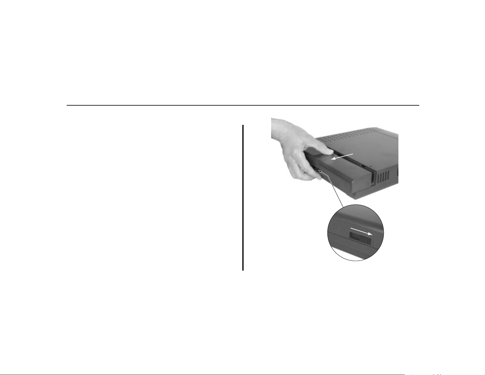
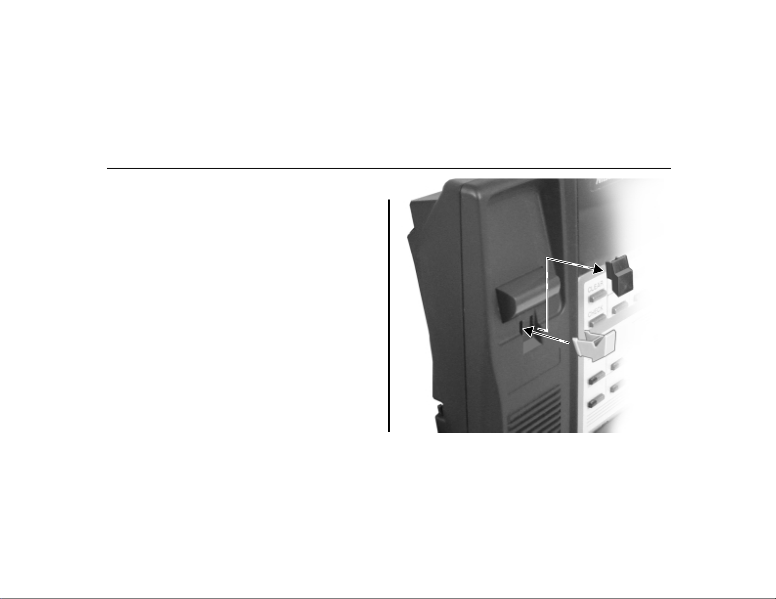
Removing the Cover (Figure 1-2)
You must remove the Main Equipment Cabinet cover to get access
to the extension, trunk and auxiliary connections.
1. Slide the cover button to OPEN.
2. Slide the cover away from the Main Equipment Cabinet.
80200 - 2
Push button
to "OPEN" position
Figure 1-2 REMOVING THE COVER
1-6
Page 9

INSTALLING THE CABINET
Hanging the Cabinet (Figure 1-3)
1. Screw suitable fasteners 11 3/16” apart in a convenient location on the MDF. Be sure to leave the fasteners “backed out”
about 3/16” from the MDF backboard.
2. Hang the cabinet as shown in Figure 1-3.
80200 - 3
11 - 3/16"
1. Installation
Basics
Figure 1-3 HANGING THE CABINET
1-7
Page 10

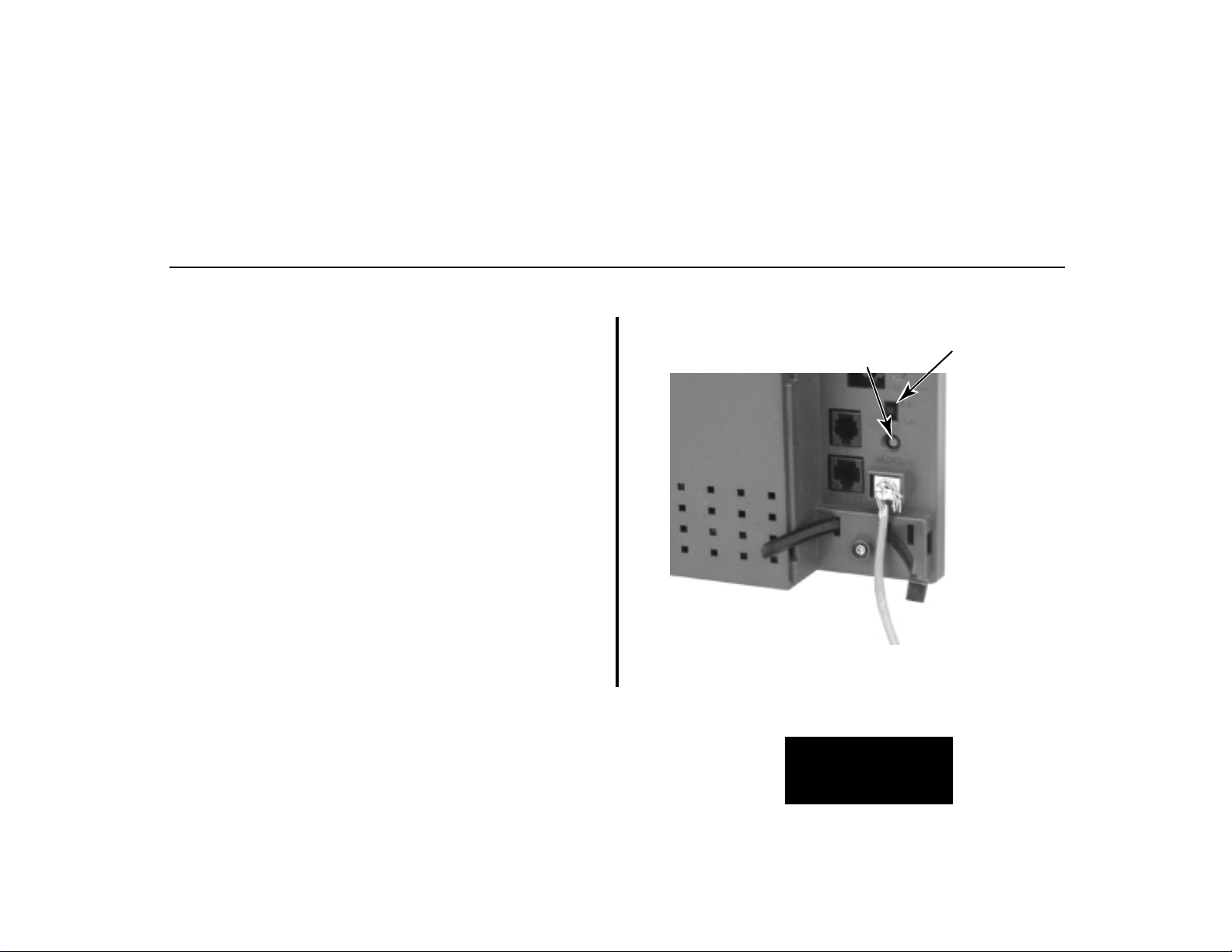
GROUNDING THE CABINET
Attaching the Ground Wire (Figure 1-4)
!! Important !!
You must connect your system to a known earth ground according the following instructions.
1. Loosen the lug on the cabinet’s ground connection.
2. Following Figure 1-4, run a 12 AWG stranded copper wire
from the ground lug to a known earth ground.
4. Firmly retighten the lug loosened in step 1 above.
80200 - 26
To earth ground
Figure 1-4 ATTACHING THE GROUND WIRE
1-8
Page 11

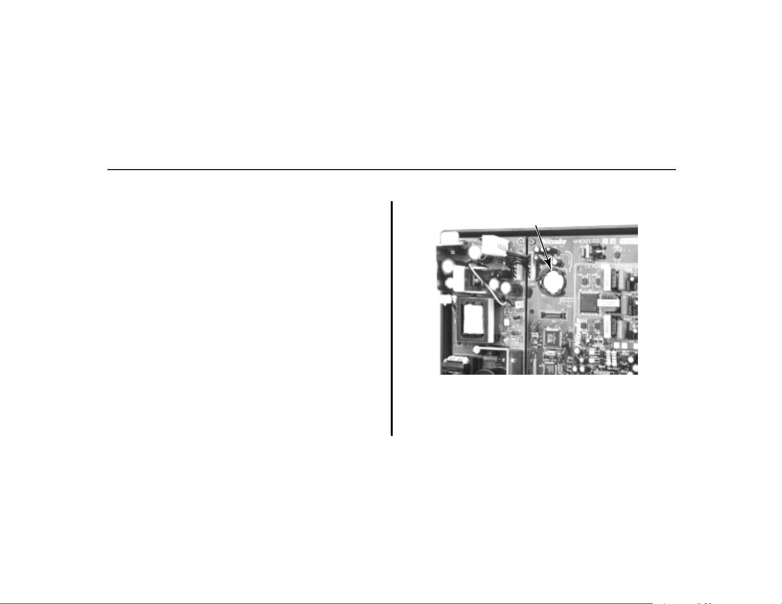
INSTALLING THE BATTERY AND EXPANSION BOARD
Removing the Top Panel (Figure 1-5)
You must remove the top panel in order to install the system
battery and Expansion Board.
In the event of commercial AC power failure, the battery provides short-term backup of system memory and the system time
and date (Real Time Clock). The battery will hold memory and
time and date for up to 10-14 days.
The Expansion Board provides an additional 3 analog trunks, 8
digital extensions, 4 analog extensions and 1 analog door box.
With the expansion board installed, the capacity of your system
is 6 analog trunks, 16 digital extensions, 8 analog extensions,
and 2 analog door boxes.
1
80200 - 4
2
● To remove the top panel:
1. Be sure your system’s power cord is unplugged, then
unscrew the 2 captive screws that secure the cabinet top
panel to the base.
2. Lift up the top panel as shown at right.
3. Remove the top panel.
1. Installation
Basics
3
Figure 1-5 REMOVING THE TOP PANEL
1-9
Page 12
INSTALLING THE BATTERY AND EXPANSION BOARD
Installing the Battery (Figure 1-6)
● To install the battery:
1. Insert the battery into the battery clips as shown at right.
2. Replace and resecure the top panel.
OR
Go to page 1-12 and install the Expansion Board.
Battery
80200 -27
Figure 1-6 INSTALLING THE BATTERY
1-10
Page 13

INSTALLING THE BATTERY AND EXPANSION BOARD
Replacing the Battery
● To replace an existing battery:
You should only need to replace your battery if it fails
to hold a charge (i.e., no longer backs up memory and
the Real Time Clock).
1. Do not power down the system.
If you power down the system and remove the battery,
programmed data and the Real Time Clock will reset
to the factory-installed default settings.
2. Following Figure 1-6, gently push down on the battery and
remove it.
3. Replace the battery with a Sony CR2032 3 Volt Lithium
cell battery or equivalent. (This battery is not available
from Nitsuko.)
4. Verify that the system’s programmed data is intact.
5. Discard the old battery.
!! Important !!
Take proper precautions when discarding the battery. It may be
considered hazardous material in some areas.
!! Caution !!
Danger of explosion if battery is incorrectly replaced.
Replace only with the same or equivalent type recommended by
the manufacturer. Dispose of used batteries according to the
manufacturer’s instructions.
1-11
1. Installation
Basics
Page 14

INSTALLING THE BATTERY AND EXPANSION BOARD
Installing the Expansion Board (Figure 1-7)
● To install the Expansion Board:
1. Be sure your system’s power cord is unplugged.
The Expansion Board is not hot-swappable.
2. Plug in the Expansion Board as shown at right.
Be sure to snap the Expansion Board into the plastic
standoffs that are supplied with the Expansion Board.
3. Replace and resecure the top panel.
80200 - 32
Figure 1-7 INSTALLING THE EXPANSION BOARD
1-12
Page 15

Section 2, EXTENSION AND TRUNK CABLING
In this section . . . Page
Before You Start Cabling . . . . . . . . . . . . . .2-3
Reviewing the Installation Method . . . . . . . . . 2-3
The Extension Block . . . . . . . . . . . . . . . . . .2-4
Installing the Extension Block . . . . . . . . . . . . 2-4
Trunk and AUX Mod Jacks . . . . . . . . . . . .2-8
Installing Trunk and AUX Mod Jacks. . . . . . . 2-8
!! Important !!
Install telephones connected to the Main Equipment Cabinet as
on-premise extensions only.
2. Extension and
Trunk Cabling
2-1
Page 16

— For Your Notes —
2-2
Page 17

BEFORE YOU START CABLING
Reviewing the Installation Method
Your system uses a different installation method for extensions
and trunk/AUX connections:
● Extension Blocks
The system uses a 66M1-50 extension block and a second
66M1-50 cross connect block for connecting extensions.
See The Extension Block on page 2-4 and the illustration on
page 2-5.
● Trunk/AUX Mod Jacks
You’ll use up to 6 mod jacks for the trunk/AUX connections.
Turn to Trunk and AUX Mod Jacks on page 2-8 for more on
this method.
Your telco normally provides trunks in RJ-11C, RJ-14C, or
RJ-25C modular jacks.
For more on connecting Door Boxes, Paging, music and power
failure, turn to Section 4, Optional Equipment.
2. Extension and
Trunk Cabling
2-3
Page 18

THE EXTENSION BLOCK
Installing The Extension Block (Figures 2-1
through 2-3).
● To connect to the extension block:
1. Arrange your extension and extension cross-connect blocks
according to the illustration below.
2. Following Figure 2-2 on page 2-6, punch down a standard
25-pair cable on the extension block.
The cable should have a female amphenol 50-pin connector on one end and be terminated on the other.
2-4
Page 19

THE EXTENSION BLOCK
80200 - 8
RS-232
DOOR1
CO 1-3
RS 232
PTF/MDAUDIO
DOOR2
CO 4-6
X10
25 Pair
Cable
6-Conductor
RJ-11X Plugs
Power Line Interface
4- or 6-Conductor
Line Cord
X10
TW 523
(Future)
Trunk/AUX
Jacks
AUDIO
DOOR
BOX 1
CO 1-3
Extension
Block
PFT
MDM
DOOR
BOX 2
CO 4-6
Do not plug in the 25-pair extension
cable with power applied.
Cross
Connect
Block
AC
Outlet
Figure 2-1 INSTALLATION LAYOUT
!! Warning !!
2-5
2. Extension and
Trunk Cabling
Page 20

Extension Assignments
25-PAIR CABLE
BLOCK
TERM
300-307 (BASE)
DIGITAL EXTENSIONS
308-315 (EXPANSION)
DIGITAL EXTENSIONS
THE EXTENSION BLOCK
(BASE)
316-319
ANALOG EXTENSIONS
320-323
(EXPANSION)
ANALOG EXTENSIONS
80200 - 5
1
2
3
4
5
6
7
8
9
10
11
12
13
14
15
16
17
18
19
20
21
22
23
24
25
26
27
28
29
30
31
32
33
34
35
36
37
38
39
40
41
42
43
44
45
46
47
48
49
50
COLOR
CODE
WHT-BLU
BLU-WHT
WHT-ORN
ORN-WHT
WHT-GRN
GRN-WHT
WHT-BRN
BRN-WHT
WHT-SLT
SLT-WHT
RED-BLU
BLU-RED
RED-ORN
ORN-RED
RED-GRN
GRN-RED
RED-BRN
BRN-RED
RED-SLT
SLT-RED
BLK-BLU
BLU-BLK
BLK-ORN
ORN-BLK
BLK-GRN
GRN-BLK
BLK-BRN
BRN-BLK
BLK-SLT
SLT-BLK
YEL-BLU
BLU-YEL
YEL-ORN
ORN-YEL
YEL-GRN
GRN-YEL
YEL-BRN
BRN-YEL
YEL-SLT
SLT-YEL
VIO-BLU
BLU-VIO
VIO-ORN
ORN-VIO
VIO-GRN
GRN-VIO
VIO-BRN
BRN-VIO
VIO-SLT
SLT-VIO
FUNCTION
300 T
300 R
301 T
301 R
302 T
302 R
303 T
303 R
304 T
304 R
305 T
305 R
306 T
306 R
307 T
307 R
308 T
308 R
309 T
309 R
310 T
310 R
311 T
311 R
312 T
312 R
313 T
313 R
314 T
314 R
315 T
315 R
316 T
316 R
317 T
317 R
318 T
318 R
319 T
319 R
320 T
320 R
321 T
321 R
322 T
322 R
323 T
323 R
NC
NC
CONN
PIN
26
1
27
2
28
3
29
4
30
5
31
6
32
7
33
8
34
9
35
10
36
11
37
12
38
13
39
14
40
15
41
16
42
17
43
18
44
19
45
20
46
21
47
22
48
23
49
24
50
25
2-62-6
Figure 2-2 EXTENSION ASSIGNMENTS
n
l-
Page 21

THE EXTENSION BLOCK
Latch
faces up
6-Pin
Mod Jack
80200 - 10
RJ-25C
Pin
1
2
3
4
5
6
Port
Designation
3T
2T
1R
1T
2R
3R
Figure 2-3 MOD PLUG PINOUTS
2. Extension and
Trunk Cabling
WHT-BLU (1T)
BLU-WHT (1R)
WHT-ORN (2T)
ORN-WHT (2R)
WHT-GRN (3T)
GRN-WHT (3R)
2-7
Page 22

TRUNK AND AUX MOD JACKS
Installing Trunk and AUX Mod Jacks (Figures 2-1
and 2-4).
● To connect to trunk mod jacks:
1. Arrange your mod jacks trunk according to Figure 2-1 on
page 2-5.
2. Using standard 6-conductor line cords, connect each mod
jack to the appropriate plug in the Main Equipment Cabinet.
3. Figure 2-4 shows the pinouts for each mod jack.
For more on connecting Door Boxes, Paging, music and
power failure, turn to Section 4, Optional Equipment.
2-8
Page 23

TRUNK AND AUX MOD JACKS
80200 - 9
Audio
GRN
WHT
Door Box 1
GRN
WHT
CO 1-3
GRN
WHT
RED
BLK
YEL
BLU
RED
BLK
YEL
BLU
RED
BLK
YEL
BLU
Page T
Page R
Music T
Music R
NC
NC
DB 1T
DB 1R
Relay 1T
Relay 1R
NC
NC
1T
1R
2T
2R
3T
3R
PFT/MDM
GRN
RED
WHT
Door Box 2
GRN
RED
WHT
CO 4-6
GRN
WHT
BLK
YEL
BLU
BLK
YEL
BLU
RED
BLK
YEL
BLU
Figure 2-4 MOD JACK ASSIGNMENTS
2. Extension and
Trunk Cabling
PFT/MDM T
PFT/MDM R
NC
NC
NC
NC
DB 2T
DB 2R
Relay 2T
Relay 2R
NC
NC
4T
4R
5T
5R
6T
6R
2-9
Page 24

— For Your Notes —
2-10
Page 25

Section 3, CONNECTING EXTENSIONS AND TRUNKS
In this section . . . Page
Connecting Extensions . . . . . . . . . . . . . . . .3-2
Connecting Extensions . . . . . . . . . . . . . . . . . . 3-2
Connecting Trunks . . . . . . . . . . . . . . . . . . .3-3
Connecting Analog Trunks . . . . . . . . . . . . . . . 3-3
Power Up the System . . . . . . . . . . . . . . . . .3-4
Power-Up. . . . . . . . . . . . . . . . . . . . . . . . . . . . 3-4
Finishing the Installation . . . . . . . . . . . . . .3-5
Reinstalling the Cover . . . . . . . . . . . . . . . . . . 3-5
3. Connecting
Extensions and Trunks
3-1
Page 26

CONNECTING EXTENSIONS
Connecting Extensions (Figure 3-1)
The base system connects 8 digital extensions and 4 analog
extensions. With the Expansion Board installed, the system provides a total of 16 digital extensions and 8 analog extensions.
1. Install a modular jack for each extension within 6 feet of the
telephone’s location.
3. For each extension, run one-pair 24 AWG station cable from
the cross-connect block to the modular jack.
4. Terminate the station cable WHT/BLU - BLU/WHT leads to
the RED and GRN lugs in the modular jack.
5. Back at the main equipment location, run one pair of crossconnect wire between the pins on the extension block and
cross-connect block to complete the connection.
6. Install bridging clips as required.
Station
Block
One-Pair
Cross Connect
Cross
Connect
Block
YEL
BLU-WHT
RED
625
Modular
Jack
BLK
WHT-BLU
GRN
Figure 3-1 CONNECTING EXTENSIONS
80200 - 11
3-2
Page 27

CONNECTING TRUNKS
Connecting Analog Trunks (Figure 3-2)
The base system connects 3 loop start CO trunks. With the
Expansion Board installed, the system provides a total of 6 loop
start CO trunks.
1. Using Figure 3-2 as a guide, install additional modular jacks
as required.
The telco may provide your trunks in a single RJ-25C
jack or in multiple RJ-11C jacks. Review the installation at right.
2. Wire the additional modular jacks as shown.
3. Plug line cords from the telco mod jacks to the system mod
jacks as shown.
80200 - 13
To CO 1-3
on DS1000
Cabinet
To CO 1-3
on DS1000
Cabinet
BLK
BLUE GRN
YEL
BLK BLUE GRN
YEL
1T
3R
2T
2R
3T
1R
WHT RED
WHT RED
(Connections for CO 1-3 shown)
1R
1T
2R
2T
3R
3T
YELWHTRED
BLKBLUEGRN
YELWHTRED
BLKBLUEGRN
YELWHTRED
BLKBLUEGRN
YELWHTRED
BLKBLUEGRN
Figure 3-2 ANALOG TRUNKS
From
Telco RJ-25C
From
Telco RJ-11C
From
Telco RJ-11C
From
Telco RJ-11C
3-3
3. Connecting
Extensions and Trunks
Page 28
POWERING UP THE SYSTEM
Power-Up (Figures 3-3 and 3-4)
Now that you have cabled the system, it is time to power-up.
● To power up the system:
1. Make sure the system is properly grounded.
2. Install a surge protector in the AC outlet.
3. Plug the main cabinet’s AC power cord into its surge protector.
4. Turn on the cabinet’s power switch.
After a brief interval, the system will start and the
power LED will flash slowly (green).
Power Switch
80200 - 14
Figure 3-3 POWER SWITCH
Figure 3-4 POWER LED
3-4
Page 29

FINISHING THE INSTALLATION
Reinstalling the Cover (Figure 3-5)
Now that your cabling is complete and the system is up and running, you should reinstall the cover.
1. Slide the cover onto the Main Equipment Cabinet as shown.
2. Slide the cover button to LOCK.
80200 - 15
Push button
to "LOCK" position
P
C
A
3. Connecting
Extensions and Trunks
Figure 3-5 REINSTALLING THE COVER
3-5
Page 30

— For Your Notes —
3-6
Page 31

Section 4, OPTIONAL EQUIPMENT
In this section . . . Page
External Paging . . . . . . . . . . . . . . . . . . . . .4-3
Installing External Paging . . . . . . . . . . . . . . . . 4-3
Analog Door Box . . . . . . . . . . . . . . . . . . . . .4-5
Installing the Analog Door Box . . . . . . . . . . . 4-4
Digital Door Box . . . . . . . . . . . . . . . . . . . . .4-8
Installing the Digital Door Box . . . . . . . . . . . . 4-8
Door Box Programming . . . . . . . . . . . . . .4-10
Programming the Door Box . . . . . . . . . . . . . 4-10
Door Box Operation . . . . . . . . . . . . . . . . .4-11
Operating the Door Box . . . . . . . . . . . . . . . . 4-11
Music Source . . . . . . . . . . . . . . . . . . . . . . .4-12
Installing a Music Source . . . . . . . . . . . . . . . 4-12
Programming Background Music . . . . . . . . . 4-13
Programming Music on Hold . . . . . . . . . . . . 4-13
In this section . . . Page
Power Failure Telephone . . . . . . . . . . . . .4-14
Power Failure Cut-Through . . . . . . . . . . . . . 4-14
DSS Console . . . . . . . . . . . . . . . . . . . . . . .4-16
Installing a DSS Console . . . . . . . . . . . . . . . 4-16
Programming DSS Consoles . . . . . . . . . . . . . 4-16
Wall-Mount Kit . . . . . . . . . . . . . . . . . . . . .4-18
Installing the Wall-Mount Kit . . . . . . . . . . . . 4-18
Installing the Wall-Mount Handset Hanger . . 4-18
Wall-Mounting a Key Telephone. . . . . . . . . . 4-19
Desk Stand . . . . . . . . . . . . . . . . . . . . . . . .4-23
Using the Desk Stand . . . . . . . . . . . . . . . . . . 4-23
REJ Recording Jack . . . . . . . . . . . . . . . . .4-24
Installing the REJ Recording Jack. . . . . . . . . 4-24
4-1
4. Optional
Equipment
Page 32

— For Your Notes —
4-2
Page 33
EXTERNAL PAGING
Installing External Paging (Figure 4-1)
Your system provides an External Paging output. You connect
the Paging output to audio inputs on customer provided
Paging systems. Zone 1 and All Call Paging announcements
broadcast from the External Paging output.
Be sure the connected Paging equipment is compatible with the
following page output specifications:
Output Impedance: 600 Ohms
Output Level: 0 dBr @ 1.0 kHz
● To connect an External Paging amplifier:
1. Connect the external Paging amplifier to the GRN and RED
lugs on the Audio modular jack.
2. Plug a 6-conductor line cord into the AUDIO jack on the
cabinet and into the Audio modular jack.
T o AUDIO in
DS1000 cabinet
BLK BLUE GRN
80200 - 17
YEL
NC
NC
WHT RED
Page T
Page R
Music T
Music R
Page Output
Music Input
Figure 4-1 INSTALLING EXTERNAL PAGING
4. Optional
Equipment
4-3
Page 34

EXTERNAL PAGING
External Paging Relay Control
You can alternately use the 2 Door Box relays to control an
External Paging amplifier. Figure 4-2 on page 4-7 shows you
the location of the Door Box relays. Note that if you use a relay
for External Paging Control, you cannot also use it for Door
Box strike control.
!! Important !!
Be sure the devices connected to the system’s relay contacts are
compatible with the following specifications.
Contact Configuration . . . . . . . . . . . . . . . . Normally Open
Maximum Load . . . . . . . . . . . . . . . . . . . . . 0.5A @ 120 VAC
1 A @ 24 VDC
Maximum Initial Contact Resistance . . . . . 100 mOhms
Connecting the Relays for External Paging Control
1. If you are using the Door 1 relays, connect the BLK and
YEL lugs on the Door Box 1 modular jack to the relay that
controls the External Paging system.
2. If you are using the Door 2 relays, connect the BLK and
YEL lugs on the Door Box 2 modular jack to the relay that
controls the External Paging system.
Connecting the Relays for External Paging Control
● In 0201: Door 1 Relay, to assign the Door 1 Relay for
External Paging control, enter 2.
● In 0201: Page Zone (Door 1 Relay), enter the Page Zone
(1-7) that should activate the Door 1 relay. Note that Zone 1
and All Call Paging announcements broadcast from the
External Paging output.
● In 0201: Door 2 Relay, to assign the Door 2 Relay for
External Paging control, enter 2.
● In 0201: Page Zone (Door 2 Relay), enter the Page Zone
(1-7) that should activate the Door 2 relay. Note that Zone 1
and All Call Paging announcements broadcast from the
External Paging output.
4-4
Page 35

ANALOG DOOR BOX
Installing the Analog Door Box (Figure 4-2)
Do not connect an Analog Door Box to a digital station port.
The Analog Door Box (P/N 92245) is a self-contained Intercom
unit typically used to monitor an entrance door. A visitor at the
door can press the Analog Door Box call button (like a door
bell). The Door Box then sends chime tones to all extensions
programmed to receive chimes. To answer the chime, the called
extension user just lifts the handset. This lets the extension user
talk to the visitor at the Door Box.
You can connect up to 2 Analog Door Boxes to your system.
The base system provides an Analog Door Box and associated
relay at extension 324. If you have the Expansion Board
installed, you have a second Analog Door Box and associated
relay at extension 325. Analog Door Boxes do not add to the
System Load Factor.
Each Analog Door box also has an associated control relay. You
can use this relay to release an electric strike on the entrance
door. After answering the Door Box chimes, the extension user
can press FLASH or a soft key to enable the Analog Door
Box’s relay, which in turn unlocks the door.
The Analog Door Box is a weather-tight unit, with an operating
temperature range of -20 to 60 degrees C (-4 to 140 degrees F)
and a relative humidity of 10-95%, non-condensing.
!! Important !!
Be sure the devices connected to the system’s relay contacts are
compatible with the following specifications.
Contact Configuration . . . . . . . . . . . . . . . . Normally Open
Maximum Load . . . . . . . . . . . . . . . . . . . . . 0.5A @ 120 VAC
1 A @ 24 VDC
Maximum Initial Contact Resistance . . . . . 100 mOhms
4-5
4. Optional
Equipment
Page 36

ANALOG DOOR BOX
● To connect an Analog Door Box:
Door Box Audio
1. Connect the GRN and RED lugs on the Door Box 1 modular
jack to terminals 1 and 2 on Analog Door Box 1 (324).
2. Connect the GRN and RED lugs on the Door Box 2 modular
jack to terminals 1 and 2 on Analog Door Box 2 (325).
Door Relays
1. Connect the BLK and YEL lugs on the Door Box 1 modular
jack to the relay that controls the door strike associated with
Analog Door Box 1 (324).
2. Connect the BLK and YEL lugs on the Door Box 2 modular
jack to the relay that controls the door strike associated with
Analog Door Box 2 (325).
Also see Programming the Door Box on page 4-10 and
Operating the Door Box on page 4-11.
4-6
Page 37

To DOOR1 in
DS1000 cabinet
ANALOG DOOR BOX
Door Box 1
BLK BLUE GRN
80200 - 30
YEL
NC
NC
WHT RED
Door Box 1T
Door Box 1R
Relay 1T
Relay 1R
Door Box 1
Relay
Figure 4-2 CONNECTING AN ANALOG DOOR BOX
4. Optional
Equipment
4-7
Page 38

DIGITAL DOOR BOX
Installing the Digital Door Box (Figure 4-3)
Do not connect a Digital Door Box to an Analog Door Box port.
The Digital Door Box (P/N 80560) is a self-contained Intercom
unit typically used to monitor an entrance door — similar in
operation to an Analog Door Box. A visitor at the door can
press the Door Box call button (like a door bell). The Door Box
then sends chime tones to all extensions programmed to receive
chimes. To answer the chime, the called extension user just lifts
the handset. This lets the extension user talk to the visitor at the
Door Box. The Door Box is convenient to have at a delivery
entrance, for example. It is not necessary to have company personnel monitor the delivery entrance; they just answer the Door
Box chimes instead.
The number of Digital Door Boxes you can install is limited by
the System Load Factor. (See page 1-4).
A Digital Door Box can control the relay contacts in the Door 1
and Door 2 connectors — just like an Analog Door Box.
Connection (see Door Relays on page 4-6), programming (see
Door Box Relay Control on page 4-10), and operation (see
Operating the Door Box on page 4-11) are identical.
The Digital Door Box is a weather-tight unit, with an operating
temperature range of 0 to 45 degrees C (32 to 113 degrees F)
and a relative humidity of 10-95%, non-condensing. It is not
intended for outdoor installation.
Any available digital extension port can support a Digital Door Box.
● To install the Digital Door Box:
1. Snap open the Door Box case.
2. Punch down one end of a two-pair twisted station cable on
the extension block as shown in Figure 4-3.
3. Run the station cable through the hole in the back of the
Door Box.
When wall mounting, use the two holes in the base of
the Door Box for the mounting screws.
4. Strip the conductors back about 1/2 inch and connect to the
Door Box terminals.
5. Snap the Door Box cover back onto the base.
Also see Programming the Door Box on page 4-10 and
Operating the Door Box on page 4-11.
4-8
Page 39

Digital Door Box
(Extension 304)
9
10
11
12
13
14
80000 - 39A
Station Cable
Lead Designations
White/Blue
Blue/White
Figure 4-3 CONNECTING A DOOR BOX
TT
TR
White/Blue
Blue/White
Mounting screws
(Customer provided)
Digital Door Box
(P/N 80560)
4-9
4. Optional
Equipment
Page 40

DOOR BOX PROGRAMMING
Programming the Door Box
Door Box Setup
You must assign the circuit type and chime pattern to each
installed Door Box.
● In 1801: Extension Circuit Type, enter 10 to assign the
extension as a Door Box. (By default, this assignment is
already made for the Analog Door Boxes.)
● In 1801: Door Chime, enter the Door Chime type.
0 = Normal Ring Group ringing.
1 = Low pitch chime pattern.
2 = Mid range pitch chime pattern.
3 = High pitch chime pattern.
If you enter Door Chime type 0 (normal ring) above,
you can set up Call Coverage keys for the Ring Group.
This allows extensions that are not members of the Ring
Group to answer Door Box calls. Extensions with Call
Coverage keys to the Door Box Ring Group can also
activate the relay (see Door Box Relay Control below).
Door Box Ringing
When a visitor at the door presses the Door Box call button, the
Door Box will alert (chime) all the extensions in the Ring
Group to which the Door Box belongs. For example, if the
Door Box and extensions 301 and 302 are in Ring Group 1,
pressing the call button alerts 301 and 302.
● In 1802: Ring Group Number, assign the Door Box and
the extensions that should alert to the same Ring Group.
● In 0511: Ring Group Master Extension Numbers and
Names, assign a Ring Group master number to the Ring
Group assigned in the previous step.
Door Box Relay Control
For Analog Door Boxes, you normally set up Door Box 1 to
control the Door 1 relays, and Door Box 2 to control the Door 2
relays (see 1801: Relay Owner below). If the Relay Owner is a
Digital Door Box instead, it can control either relay.
● In 0201: Door 1 Relay, to assign the Door 1 Relay for door
strike control, enter 1.
● In 0201: Door 2 Relay, to assign the Door 2 Relay for door
strike control, enter 1.
● In 1801: Relay Owner, for the Door Box extension (324,
325, or the Digital Door Box extension number):
- Enter 1 to have the Door Box control Door 1 relays.
- Enter 2 to have the Door Box control Door 2 relays.
4-10
Page 41

DOOR BOX OPERATION
Operating the Door Box
To place a call from the Door Box:
1. Press the Door Box call button.
2. When someone inside the building answers your call, speak
toward the Door Box.
To place a call to the Door Box:
1. Lift handset and press ICM.
2. Dial the Door Box extension number.
To answer the Door Box chimes from a keyset:
1. Lift handset or press SPK .
To control the system relay which in turn controls the
door strike:
Once set up in programming, this option is available
to any member of the Door Box Ring Group as well as
any extension with a Call Coverage Key for the Door
Box Ring Group.
1. To open the relay, press FLASH key or OPEN soft key.
2. To close the relay, press FLASH key again or CLOSE soft key.
4-11
4. Optional
Equipment
Page 42

Installing a Music Source (Figure 4-4)
Your system provides connection for a customer provided
music source. Use this music source for Background Music
and Music on Hold.
Be sure the connected music source is compatible with the following music input specifications:
Input Impedance: 10K Ohms
Output Level: +18 dBr @ 1.0 KHz
● To connect a music source:
1. Connect the music source to the BLK and YEL lugs on the
Audio modular jack.
2. Plug a 6-conductor line cord into the AUDIO jack on the
cabinet and into the Audio modular jack.
MUSIC SOURCE
T o AUDIO in
DS1000 cabinet
BLK BLUE GRN
80200 - 17
YEL
NC
NC
WHT RED
Page T
Page R
Music T
Music R
Page Output
Music Input
Figure 4-4 INSTALLING A MUSIC SOURCE
4-12
Page 43

Programming Background Music
● 0201: Background Music
Enter Y to enable Background Music system-wide.
● 1802: BGM
Enter Y to enable Background Music at the extension.
Programming Music on Hold
● 0201: Music on Hold
Enter Y to enable Music on Hold system-wide.
● 0201: MOH on Transfer
Enter Y to enable Music on Hold for transferred calls.
MUSIC SOURCE
4. Optional
Equipment
4-13
Page 44

POWER FAILURE TELEPHONE
Power Failure Cut-Through (Figure 4-5)
(Check the Release Notes that came with your system for the
availability of this option.)
When AC power fails, the system can automatically cut through
to a Power Failure Telephone connection.
● To install Power Failure Cut-Through:
1. Connect the GRN and RED lugs on the PFT/MDM modular
jack to the GRN and RED lugs on the Power Failure
Telephone’s mod jack.
● To test the Power Failure Telephone:
1. Connect a power failure telephone per Figure 4-5.
2. Power down the system.
3. At the Power Failure Telephone, lift the handset.
You should hear dial tone from trunk 1.
4. Place a test call.
If power is restored while a cut-through call is in
progress, the call is maintained until the user hangs up
the Power Failure Telephone.
While your system is powered up, your Power Failure
Telephone is extension 316.
4-14
Page 45

POWER FAILURE TELEPHONE
BLK BLUE GRN
To PFT/MDM in
DS1000 cabinet
80200 - 21
YEL
NC
NC
WHT RED
NC
NC
PFT
PFR
Power
Failure
Telephone
Power Failure
Telephone
GRN RED
BLK YEL
625
Modular
Jack
BLU-WHTWHT-BLU
Figure 4-5 CONNECTING A POWER FAILURE TELEPHONE
4. Optional
Equipment
4-15
Page 46

DSS CONSOLE
Installing a DSS Console (Figures 4-6 and 4-7)
The DSS Console gives a keyset user a Busy Lamp Field (BLF)
and one-button access to extensions, trunks and system features.
Keep the following in mind when installing DSS Consoles:
● You can only connect 4 DSS Consoles.
● You can only connect DSS Consoles to Super Display or
34-Button Display telephones.
● A DSS Console does not require a separate station port – it
connects directly to the keyset.
● To install a DSS Console:
1. Turn the telephone upside down and remove the plastic filler
plug from the DSS modular connector.
2. Plug the DSS Console’s 8-pin modular line cord into the
telephone’s DSS connector.
3. Plug the other end of the 8-pin line cord into the DSS
Console’s 8-pin jack.
4. If you have a 24-Button DSS Console, attach the metal plate
to both the DSS Console and telephone as shown.
Programming DSS Consoles
● 1801: DSS Type
For the extension to which you have connected the DSS Console,
enter 1 for 24-button, 2 for 110-button and 0 for unassigned.
● 1801: DSS Block Number
For the extension to which you have connected the DSS
Console, enter the number of the block that corresponds to the
connected console. Ablock is a unique DSS Console assignment. The system provides up to 4 blocks; one for each console.
Your consoles can share the same block if you want
them to have the same programming. They will still
have unique Personal Speed Dial numbers, since a
DSS Console uses the Personal Speed Dial for the
extension to which it is attached.
● 1704: DSS Console Key Assignment
Program the DSS Console's keys. Refer to the software manual
for additional programming details.
4-16
Page 47

80000 - 44
DSS CONSOLE
To 625 Modular Jack
To 625 Modular Jack
DSS Console Keyset
80000 - 47
DSS Console Keyset
Figure 4-6 INSTALLING A 110-BUTTON DSS CONSOLE Figure 4-7 INSTALLING A 24-BUTTON DSS CONSOLE
4. Optional
Equipment
4-17
Page 48
WALL-MOUNT KIT
Installing the Wall-Mount Kit
You can use a wall-mount kit to attach any key telephone to a
wall. The wall-mount kit includes a mounting bracket, wallmount screws and a handset hanger.
Installing the Wall-Mount Handset Hanger (Figure 4-8)
1. Remove the rubber plug that covers the slots for the handset
hanger. Store the plug in a safe place.
2. Insert the handset hanger in the slot provided beneath the
telephone’s hookswitch.
80000 - 38
Figure 4-8 INSTALLING THE WALL-MOUNT HANGER
4-18
Page 49

WALL-MOUNT KIT
Wall-Mounting a Key Telephone (Figures 4-9
through 4-11)
● To mount the telephone on the wall (Figure 4-9):
1. Using the screws provided, attach the wall-mount bracket to
the wall in the desired location.
2. Plug in the telephone’s modular line cord.
3. Run the telephone’s line cord through one of the slots in the
bottom of the wall-mount bracket.
4. Plug the line cord into the telephone’s 625 modular jack.
5. Place the telephone on top of the wall-mount bracket and
snap into place.
80000 - 42
Run cord
through
slot
To wall jack
Tab on phone must snap
into cutout on wall mount bracket
Figure 4-9 INSTALLING THE WALL MOUNT BRACKET
4. Optional
Equipment
4-19
Page 50

WALL-MOUNT KIT
● To mount the telephone on a wall plate (Figure 4-10):
1. Snap the wall-mount bracket onto the wall plate.
2. Plug the telephone’s line cord into the jack in the wall plate
and into the telephone.
3. Place the telephone on top of the wall-mount bracket and
snap into place.
80000 - 43
Tab on phone must snap
into cutout on wall mount bracket
Figure 4-10 MOUNTING ON A WALL PLATE
4-20
Page 51

WALL-MOUNT KIT
● To remove the telephone from the wall mount kit
(Figure 4-11):
1. From the front of the phone, grab the tabs that secure the
telephone to the wall-mount kit.
2. While pressing in the tabs, lift up the phone until it snaps
clear of the wall-mount kit.
80000 - 45
Press down tabs
on phone and
pull bracket in
direction of arrows
Figure 4-11 REMOVING THE WALL MOUNT BRACKET
4. Optional
Equipment
4-21
Page 52

— For Your Notes —
4-22
Page 53

Using the Desk Stand (Figure 4-12)
Each telephone has an integrated desk stand. You can extend
the desk stand in one of two positions: low and high.
● To use the desk stand low position:
1. Flip up each telephone leg until it snaps into place.
● To use the desk stand high position:
1. Flip up each telephone leg into the low position.
2. Push out the leg extender.
3. Slide the extender up, then down until it locks in place as
shown at right.
DESK STAND
80000 - 46
Figure 4-12 USING THE DESK STAND
4. Optional
Equipment
4-23
Page 54

REJ RECORDING JACK
Installing the REJ Recording Jack (Figure 4-13)
Use the REJ Recording Jack (P/N 80175) to connect a Super
Display or 34-Button Display Telephone to an external tape
recorder or amplifier. The REJ output is a mono sub-miniature jack
which connects directly to an AUX level input. The REJ broadcasts
both sides of your conversation (i.e., your voice and your caller’s
voice) whenever you lift your handset. The REJ does not broadcast
Paging announcements or activate for Handsfree calls.
CAUTION
Be sure the connected audio device provides a standard AUX
level input.
● To install the REJ Recording Jack:
1. Unplug the telephone line cord and handset cord, and turn
the telephone face down on a non-abrasive surface.
2. Remove the 4 screws that secure the telephone base.
3. Separate the telephone faceplate from the telephone base.
4. On the left side of the telephone base, remove the plastic
molding that covers the hole for the REJU connector. You
only need to remove the top half of the molding.
5. Install the REJ as shown (with the components facing down).
6. Secure with the supplied screw.
● To connect the REJ Recording Jack:
1. Route the REJ wires through the guides in the telephone base.
2. Plug the REJ cable into the connector in the telephone PCB.
The connector is keyed so you can’t plug in the cable
the wrong way.
3. Reassemble the telephone, plug in the handset, and reconnect the line cord.
4. Using an audio cable, connect the REJ to the amplifier’s
mono AUX input.
To connect to a stereo AUX input, use a commercially
available mono-to-stereo splitter cable.
4-24
Page 55

80000 - 48
To mono AUX input on amplifier
REJ RECORDING JACK
Red wire
Figure 4-13 INSTALLING THE REJ
4. Optional
Equipment
4-25
Page 56

REJ RECORDING JACK
— For Your Notes —
4-26
Page 57

Section 5, MAINTENANCE OPTIONS AND SMDR
In this section . . . Page
SMDR . . . . . . . . . . . . . . . . . . . . . . . . . . . . .5-2
Installing SMDR . . . . . . . . . . . . . . . . . . . . . . 5-2
Programming SMDR . . . . . . . . . . . . . . . . . . . 5-2
Modem Installation . . . . . . . . . . . . . . . . . . .5-4
Installing a Modem. . . . . . . . . . . . . . . . . . . . . 5-4
In this section . . . Page
Making your own Data Cables . . . . . . . . . .5-6
System Reset . . . . . . . . . . . . . . . . . . . . . . . .5-7
Resetting Your System . . . . . . . . . . . . . . . . . . 5-7
5-1
5. Maintenance
Options and SMDR
Page 58

SMDR
Installing SMDR (Figure 5-1)
Station Message Detail Recording (SMDR) provides a record
of the system’s outside calls. Once set up in programming,
SMDR automatically outputs from the system’s RS-232 (serial)
port to a customer-provided printer, terminal or SMDR data
collection device.
You can also connect a PC to the system serial port to
collect call history data.
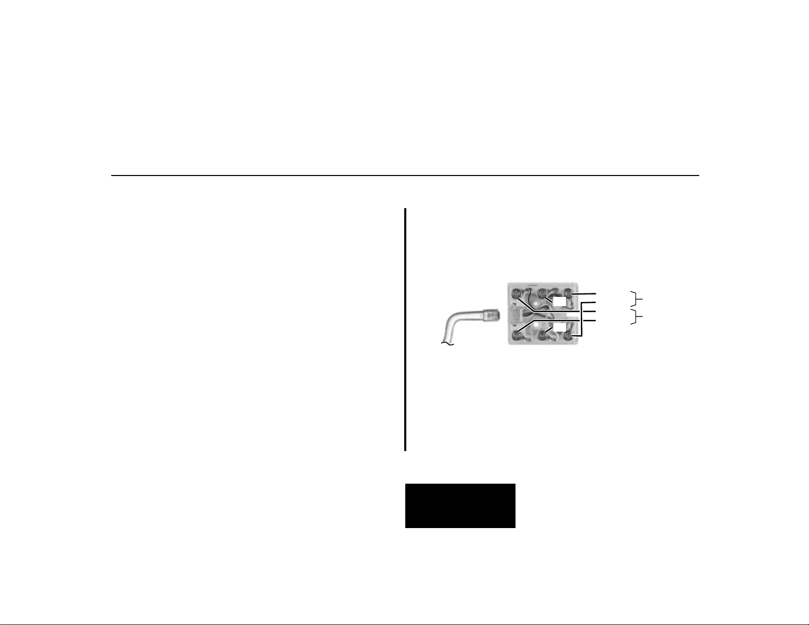
● To connect an SMDR device:
1. Plug one end of a mod-8 (standard 8 conductor) patch cord
into the system’s RS-232 port.
2. Plug the other end of the mod-8 patch cord into the DB9 to
Mod-8 Adaptor (P/N 85980).
3. Plug the adaptor into the DB9M COM connector on the back
of your PC.
The default communications parameters of the CPU
serial port are 19200 8 N 1 (19200 baud, eight data
bits, no parity and 1 stop bit).
If you have a PC connected to collect history data,
press Shift 1 to turn history on and off.
Programming SMDR
● 0301: CPU Baud Rate
Assign the baud rate for the RS-232-C port on the CPU. The
options are 0 (1200), 1 (2400), 2 (4800), 3 (9600), 4 (19200),
and 5 (38400).
You can also press Ctrl Break on a PC connected to
the system serial port to toggle through the available
system baud rates.
● 0301: SMDR Port
Enter 1 to enable SMDR output from the system’s RS-232-C port.
● 0301: Print SMDR Header
Enter Y to have the beginning of the SMDR report include the
column header data. Enter N to have the SMDR report only
include the call data (without the header).
● 1001: Print SMDR
Enter Y to have the SMDR report include calls on the trunk.
Enter N to have the SMDR report exclude calls on the trunk.
5-2
Page 59

80200 - 23
SMDR
RS-232 Port
Mod 8
Patch Cord
Figure 5-1 CONNECTING SMDR
DB9M COM PORT
P/N 85980
5-3
5. Maintenance
Options and SMDR
Page 60

MODEM INSTALLATION
Installing a Modem (Figure 5-2)
You can connect a modem to the system’s serial port to remotely collect history data and/or SMDR.
● To connect a modem:
1. Plug one end of a mod-8 (standard 8 conductor) patch cord
into the system’s RS-232 port.
2. Plug the other end of the mod-8 patch cord into the DB25 to
Mod-8 Adaptor (P/N 85981).
3. Plug the other end of the adaptor into the DB25F connector
on the back of your modem.
The default communications parameters of the system’s
serial port are 19200 8 N 1 (19200 baud, eight data
bits, no parity and 1 stop bit).
If you have a PC connected to collect history data,
press Shift 1 to turn history on and off.
● To call from a PC at a remote site:
The remote PC must have a modem connected. Also,
the default communications parameters of the system’s
serial port are 19200 8 N 1 (19200 baud, eight data
bits, no parity and 1 stop bit).
1. Using commercially available communications software, dial
the phone number of the trunk connected to the modem at
the telephone system site.
2. To test history, type Shift 1 on the remote PC.
If history doesn’t output correctly, press Ctrl Break on
the remote PC to toggle through the available CPU
baud rates.
5-4
Page 61

80200 - 24
RS-232 Port
MODEM INSTALLATION
To trunk
P/N 85981
Mod 8
Patch Cord
Figure 5-2 CONNECTING A MODEM
Modem Power
Supply
5-5
5. Maintenance
Options and SMDR
Page 62

MAKING YOUR OWN DATA CABLES
80200 - 25
1
2
3
4
5
6
7
8
DSR
DCD
DTR
SG
RD
TD
CTS
RTS
Mod-8Mod-8
8
1
Latch faces
down
8
1
1
2
3
4
5
6
7
8
80200 - 35
DSR
DCD
DTR
SG
RD
TD
CTS
RTS
8
1
Mod-8
1
2
3
4
5
6
7
8
5 1
9
DB-9
4
1
6
5
3
2
7
8
9
6
DTR
DCD
DSR
SG
TD
RD
RTS
CTS
R1
Figure 5-3 MAKING YOUR OWN DATA CABLES
80200-36
DSR
DCD
DTR
SG
RD
TD
CTS
RTS
8
1
Mod-8
1
2
3
4
5
6
7
8
1 13
14
DB-25
6
DSR
8
DCD
20
DTR
7
SG
3
RD
2
TD
5
CTS
4
RTS
25
5-6
Page 63
SYSTEM RESET
Resetting Your System (Figure 5-4)
You may need to reset your system for troubleshooting purposes.
● To reset your system:
1. Make sure the RUN/LOAD switch is set to RUN.
2. Following the illustration at right, press the red reset switch.
Your system will automatically restart.
80200 - 31
FIGURE 5-4 RESETTING YOUR SYSTEM
Reset Switch
5. Maintenance
Options and SMDR
RUN/LOAD
Switch
5-7
Page 64

— For Your Notes —
5-8
Page 65

Section 6, SPECIFICATIONS AND PARTS LIST
In this section . . . Page
Specifications . . . . . . . . . . . . . . . . . . . . . . .6-2
Parts List . . . . . . . . . . . . . . . . . . . . . . . . . . .6-6
6-1
6. Specifications
and Parts
Page 66

SPECIFICATIONS
System Capacities
Cabinets: 1
Talk Timeslots (Intercom/line): Non-blocking
Analog Trunks (CO/PBX lines): Base: 3
Expansion: 3
Total: 6
Digital Telephones: Base: 8
Expansion: 8
Total: 16
Analog Telephones: Base: 4
Expansion: 4
Total: 8
Door Boxes (digital): 1 per digital station port
Door Boxes (analog) Base: 1
Expansion: 1
Total: 2
System Capacities
Power Failure Telephones: 1
DSS Consoles: 1 max. per keyset, 4 max.
per system
External Paging Zones: 1
Internal Paging Zones: 8 (7 and All Call)
Page Audio Output: 1
Music Input: 1
Conference Circuits Conference circuits dynam-
ically allocated, with 8 par-
ties max. per Conference.
REJ Recording Jack Units 1 max. per keyset
6-2
Page 67
SPECIFICATIONS
Environmental Requirements
Meeting established environmental standards maximizes the
life of the system. Refer to the Standard Practices Manual for
further information. Be sure that the site is not:
1. In direct sunlight or in hot, cold or humid places.
2. In dusty areas or in areas where sulfuric gases are produced.
3. In places where shocks or vibrations are frequent or strong.
4. In places where water or other fluids comes in contact with
the main equipment.
5. In areas near high-frequency machines or electric welders.
6. Near computers, telexes, microwaves, air conditioners, etc.
7. Near radio antennas (including shortwave).
Power Requirements
A dedicated 110 VAC 60 Hz circuit located within 4 1/2 feet
of the cabinet is required.
Environmental Specifications
Cabinet, Key Telephones and Digital Door Box
Temperature: 0-45oC (32-113oF)
Humidity: 10-95% (non-condensing)
Digital Door Box not intended for outdoor installation.
Analog Door Box
Temperature: -20-60oC (4-140oF)
Humidity: 10-95% (non-condensing)
Electrical Specifications
Power Supply: 120 VAC ±- 10% @ 50-60 Hz
Output Power 35 W
Input Current 550 mA
VA 66 VA
Kwh .066 KwH
BTU 225 BTU
Grounding Requirements: 12 AWG copper wire
6-3
6. Specifications
and Parts
Page 68

SPECIFICATIONS
Mechanical Specifications
Equipment Width Depth Height Weight
Cabinet 13 3/4”” 2 1/2”” 10 1/2” 4 lbs 1 oz
Non-display Keyset 7 1/4” 9” 2 7/8”” 1 lb 11 oz
Display Keyset 7 1/4” 9” 2 7/8” 1 lb 12 oz
Super Display Keyset 7 1/4” 9” 2 7/8” 1 lb 16 oz
DSS Console 7 7/8” 8 7/8” 2 3/4” 1 lb 6 oz
Analog Door Box 3 3/4” 1” 5” 6 oz
Digital Door Box 4” 1 1/2” 5 3/16” 10 oz
2-OPX Module 9 3/8” 7 3/8” 1 1/4” 3 lbs
External Paging
Output Impedance: 600 Ohm
Output Level: 0 dBr @ 1.0 KHz
Relay Contacts
Contact Configuration: Normally open
Maximum Load: 0.5A @ 120 VAC
1A @ 24 VDC
Maximum Carry Current 2A
Maximum Switched Voltage 120 VAC or 60 VDC
Maximum Switched Power 60 VA or 24 W
Minimum Switched Current 1 mA
Minimum Switched Voltage 1 VDC
Minimum Switched Power 0.05 mW
Maximum Initial Contact Resistance: 100 mOhms
6-4
Page 69
SPECIFICATIONS
BGM/MOH Music Source Input
Input Impedance: 10K Ohms
Input Level: +18 dBr (+/- 2 dBr) @ 1.0
KHz
FCC Registration Information
Model: DS1000
Manufacturer: Nitsuko
FCC Part 15 Registration: Class A
FCC Registration Number: 1ZDTHA-35391-KF-E
1ZDTHA-35392-MF-E
Industry Canada
Certificate (DOC) Number TBD
Reg. FIC Mfrs. Port Network
Status Identifier Jacks
Original 02LS2 80200 REN 0.6B RJ11C
Cabling Requirements
1. Do not run station cable parallel with the AC source, telex or computer, etc. If the cables are near cable runs to those devices, use
shielded cable with grounded shields or install the cable in conduit.
2. When cables must be run on the floor, use cable protectors.
3. Cable runs for key telephones, single line telephones, Door Boxes
and 3-ACI Modules must be a dedicated, isolated cable pair.
Device Cable Type Cable Run Length (ft) Notes
Key Telephone & 2-wire 26 AWG 650
Digital Door Box 2-wire 24 AWG 1000
Single Line 2-wire 26 AWG 8000 at constant 20 mA
Telephone 2-wire 24 AWG 12,000 at constant 20 mA
2-wire 22 AWG 16,000 at constant 20 mA
Analog Door Box 2-wire 24 AWG 330
2-wire 22 AWG 550
6-5
6. Specifications
and Parts
Page 70

PARTS LIST
Station Equipment
Description Part Number
34-Button Super Display Telephone 80673
34-Button Display Telephone 80663
22-Button Telephone 80570
22-Button Display Telephone 80573
24-Button DSS Console 80556
110-Button DSS Console 80555
Wall Mount Kit 80579
Analog Telephones (customer provided)
Peripheral Station Equipment
Description Part Number
Digital Door Box 80560
Analog Door Box 92245
Common Equipment
Description Part Number
DS1000 3 x 8 x 4 Cabinet 80200
DS1000 3 x 8 x 4 Expansion Board 80221
DB9 to Mod-8 Adaptor 85980
DB25 to Mod-8 Adaptor 85981
6-6
Page 71

PARTS LIST
Replacement Parts
Description Part Number
Handset and Cord Assembly 80150
Noise Cancelling Handset 80150NC
22 Button Clear Plastic Cover 80600-22
34 Button Clear Plastic Cover 80600-34
34 Button Super Display Clear Plastic Cover 80600-S34
110 Button DSS Clear Plastic Cover 80600-DSS
24 Button DSS Clear Plastic Cover 80600-24DSS
Directory Tray 92602
9’ Handset Coil Cord 92297-9
13’ Handset Coil Cord 92297-13
25’ Handset Coil Cord 92297-25
7’ Telephone Line Cord 82476-7
14’ Telephone Line Cord 82476-14
Wall Mount Handset Clip Holder 80578
6-7
6. Specifications
and Parts
Page 72

— For Your Notes —
6-8
Page 73

Nitsuko America, Telecom Division
4 Forest Parkway
Shelton, CT 06484
TEL: 203-926-5400
FAX: 203-929-0535
Other Important Telephone Numbers
Sales: . . . . . . . . . . . . . . . . . . . . . . . . . . . . . . . . . . . . . . . .203-926-5450
Customer Service: . . . . . . . . . . . . . . . . . . . . . . . . . . . . . .203-926-5444
Customer Service FAX: . . . . . . . . . . . . . . . . . . . . . . . . . .203-926-5454
Technical Service: . . . . . . . . . . . . . . . . . . . . . . . . . . . . . .203-925-8801
Discontinued Product Service: . . . . . . . . . . . . . . . . . . . . .900-990-2541
Technical Training: . . . . . . . . . . . . . . . . . . . . . . . . . . . . . .203-926-5430
Emergency Technical Service (After hours) . . . . . . . . . . .203-929-7920
(Excludes discontinued products)
Nitsuko Canada, Division of Nitsuko America
165 Matheson Blvd. E., Unit #4-6
Mississauga, Ontario Canada L4Z 3K2
TEL: 905-507-2888, FAX: 905-507-2971
Th
6-9
co
Page 74

4 Forest Parkway
Shelton, CT 06484
TEL: 203-926-5400 FAX: 203-929-0535
165 Matheson Blvd. E., Unit #4-6,
Mississauga, Ontario Canada L4Z 3K2
TEL: 905-507-2888 FAX: 905-507-2971
 Loading...