


28i/124i/384i
Hardware Manual

28i/124i
Hardware Manual
1. Installing |
2. PCB Installation |
3. Installing |
4. Optional |
5. Data |
6. Specifications |
Cabinets |
and Startup |
Extensions and Trunks |
Equipment |
and SMDR |
and Parts |
|
|
|
|
|
|
92601INS08 January 1999

Section 1, INSTALLING THE MAIN AND EXPANSION CABINETS
In this section . . . . . . . . . . . . . . . .Page
Installing the Cabinets . . . . . . . . . . . . . . . .1-3
Unpacking . . . . . . . . . . . . . . . . . . . . . . . . . . . 1-3
Before Installing . . . . . . . . . . . . . . . . . . . . . . . 1-3
Site Requirements. . . . . . . . . . . . . . . . . . . . . . 1-3
Removing the 28i Covers . . . . . . . . . . . . . . . . 1-4
Mounting the 28i Cabinets . . . . . . . . . . . . . . . 1-4
Removing the 124i Covers . . . . . . . . . . . . . . . 1-5
Mounting the 124i Cabinets . . . . . . . . . . . . . . 1-5
Connecting Expansion Cabinets . . . . . . . . .1-8
Installing EXIFU PCBs . . . . . . . . . . . . . . . . . 1-8
Grounding the Cabinets . . . . . . . . . . . . . .1-10
Connecting the Ground Wires - 28i System . 1-10
Connecting the Ground Wires - 124i System. 1-11
1-1
1. Installing
Cabinets

INSTALLING THE CABINETS
Unpacking |
Site Requirements |
Unpack the equipment and check it against your equipment lists. Inspect for physical damage. If you are not sure about a component’s function, review the Product Description Manual. Contact your Sales Representative if you have additional questions.
Have the appropriate tools for the job on hand, including: a test set, a punch down tool and a digital voltmeter.
Before Installing
Make sure you have a building plan showing the location of the common equipment, extensions, the telco demarcation and earth ground. In addition, the installation site must meet the requirements outlined in the Standard Practices Manual.
1. Installing
Cabinets
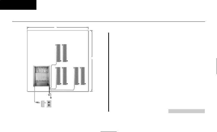
The common equipment is contained in three wall-mounted cabinets: the Main Cabinet and two Expansion Cabinets. Choose a central location for the cabinets that allows enough space for the equipment — and provides enough room for you to comfortably work. The Installation Layout (Figure 1-4 and Figure 1-5 on pages 1-6 and 1-7) shows you about how much space your system requires.
Each common equipment cabinet requires a three-prong dedicated 110 VAC 60 Hz circuit (NEMA 5-15 receptacle) located within 7 feet of the AC receptacle. You should install the extension and trunk blocks to the right of the Main Cabinet. Telco should also install the RJ21X to the right of the Main Cabinet.
1-3

1. Installing
Cabinets
INSTALLING THE 28i CABINET
Removing the 28i Cover (Figure 1-1)
To make installation easier, remove the cover on the KSU.
1.Unscrew the two captive screws on the front of the cabinet cover.
2.Lift up slightly on the front of the cover – then gently slide the cover back to remove it.
12 - 80000
Mounting the 28i Cabinet (Figure 1-2)
1.Using the screws provided, attach the metal bracket to the Main Distribution Frame (MDF) plywood backboard. Mount the bracket in a convenient location, about 12” higher than where you want the bottom of the cabinet to line up.
2.Hang the KSU on the metal bracket.
3.Install two mounting screws (provided) in the lower left and right hand corners of the KSU to secure it to the plywood backboard.
The right side panel of the KSU can also be taken off by removing the screws at the top and bottom of the side panel.
80000-13
Figure 1-1 REMOVING THE 28i COVER
Figure 1-2 HANGING THE 28i CABINET |
1-4 |

INSTALLING THE 124i CABINETS
Removing the 124i Covers (Figure 1-3)
To make wall-mounting easier, remove the cover on each common equipment cabinet. This allows you to use the cabinets as a mounting template.
1.Unscrew the two captive screws on the right side of the cabinet cover.
2.Lift up the right side of the cover — then slide the cover to the left to remove it.
92001 - 29
Mounting the 124i Cabinets (Figure 1-4 and Figure 1-5)
1.Using suitable fasteners, mount a Main Distribution Frame (MDF) plywood backboard in a centrally located spot.
2.Hold the Main Cabinet against the MDF and mark all four mounting holes.
3.Drill the marked holes using a 1/8” drill bit.
4.Install two mounting screws (provided) in the top two holes, leaving about 3/8” shank exposed.
5.Hang the Main Cabinet on the top two screws and fasten in place.
6.Install the bottom two screws and tighten in place.
7.Following the procedure above, install the expansion cabinets (if required).
Figure 1-3 REMOVING THE 124i COVER |
1-5 |
|
1. Installing
Cabinets
1. Installing
Cabinets
INSTALLING THE CABINETS
Plywood backboard
4'
15 - 80000
Trunk
Blocks
4'
Station |
Station |
Blocks |
Blocks |
To telco
ground
To earth ground
Dedicated
AC Outlet
Surge
Protector
Continued on next page. . .
Figure 1-4 28i INSTALLATION LAYOUT
1-6

Installing .1 Cabinets
LAYOUT INSTALLATION 5-1 Figure
7-1
Plywood Backboard
4’ |
|
|
Trunk Blocks |
Station Blocks |
|
|
To |
To |
|
Telco |
Stations |
Expansion Cabinet #2
4’
Trunk Blocks |
Station Blocks |
|
|
To |
To |
|
Telco |
Stations |
Expansion Cabinet #1
Trunk Blocks |
Station Blocks |
|
|
To |
To |
|
Telco |
Stations |
Main Cabinet
To Verified
Earth Ground
|
Note: Each cabinet |
|
Surge |
is shown in a typical |
|
8 x 24 configuration. |
||
Protector |
||
|
||
|
Dedicated |
|
|
AC Outlet |
Surge
Protector
Dedicated
AC Outlet
Surge
Protector
Dedicated
AC Outlet
CABINETS THE INSTALLING

1. Installing
Cabinets
CONNECTING EXPANSION CABINETS
Installing EXIFU PCBs on the 124i (Figure 1-6)
Each 124i expansion cabinet requires an EXIFU Expansion Interface PCB.
To connect Expansion Cabinet #1 to the Main Cabinet:
1.In Expansion Cabinet #1, plug the EXIFU PCB into the first (CPRU) slot.
2.Plug the EXIFU PCB ribbon cables into the two connectors at the top of the Main Cabinet backplane.
3.Install the ferrite filters as shown.
4.Install the metal strain reliefs in both the Main and Expansion #1 cabinets.
To connect Expansion Cabinet #1 to Expansion Cabinet #2:
1.In Expansion Cabinet #2, plug the EXIFU PCB into the first (CPRU) slot.
2.Plug the EXIFU PCB ribbon cables into the two connectors at the top of Expansion Cabinet #1.
3.Install the metal strain reliefs in both expansion cabinets.
1-8

CONNECTING EXPANSION CABINETS
Expansion CEU #2 |
EXIFU-S1 PCB |
 AC Cord
1. Installing
Cabinets
Expansion CEU #1 |
EXIFU-S1 PCB |
Main CEU |
Ferrite Filters
92001 - 30a
 AC Cord
1-9
Figure 1-6 CONNECTING EXPANSION CABINETS

1. Installing
Cabinets
GROUNDING THE CABINETS
Connecting the Ground Wires on the 28i System
(Figure 1-7)
The 28i cabinet has two ground connections: ETH (Earth Ground) and PBXG (PBX Ground).
1.Using 12 AWG stranded copper wire, wind three turns of the ground wire around the core.
2.Loosen the lugs on both ground connections.
3.Using 12 AWG stranded copper wire, run a short jumper between the ETH and PBXG lugs.
4.Using the piece of 12 AWG stranded copper wire that is wrapped around the core, connect the PBXG connection to a known earth ground.
5.Firmly tighten both the ETH and PBXG connections.
6.Using the plastic strap located at the base of the cabinet, secure the core to the cabinet.
DO NOT PLUG IN THE CABINET POWER CORD WITHOUT FIRST INSTALLING THE PCBS.
To telco ground
To earth ground
92700-04
Figure 1-7 GROUNDING A CABINET
1-10

GROUNDING THE CABINETS
Connecting the Ground Wires on the 124i System (Figure 1-8)
Each 124i cabinet has two ground connections: ETH (Earth Ground) and PBXG (PBX Ground).
1.Loosen the lugs on both ground connections.
2.Using 12 AWG stranded copper wire, run a short jumper between the ETH and PBXG lugs.
3.Using another piece of 12 AWG stranded copper wire, connect the PBXG connection to a known earth ground.
4.Firmly tighten both the ETH and PBXG connections.
DO NOT PLUG IN THE CABINET POWER CORDS WITHOUT FIRST INSTALLING THE PCBS.
ONCE ALL THE PCB’S HAVE BEEN INSTALLED AND THE CONNECTIONS MADE, YOU MUST REPLACE THE KSU’S COVER IN ORDER TO KEEP THE PCB’S IN PLACE AND TO PREVENT INTERMITTENT RESETS FROM A LOOSE PCB.
1. Installing
Cabinets
Jumper
To Verified 


Earth Ground
ETH PBXG
926 - 43
Figure 1-8 GROUNDING A CABINET
Now that your cabinets are installed and grounded, go to Part
2: PCB Installation and Startup.
1-11
Section 2, PCB INSTALLATION AND STARTUP
In this section . . . . . . . . . . . . . .Page
28i Hardware Information . . . . . . . . . . . . .2-2
System Load Factors . . . . . . . . . . . . . . . . . . . 2-2
PCB Location . . . . . . . . . . . . . . . . . . . . . . .2-3
Where to Install the PCBs in a 28i System . . . 2-3 Where to Install the PCBs in a 124i System . . 2-4
Installing PCBs . . . . . . . . . . . . . . . . . . . . . .2-4
Advanced Feature (EXCPRU) Module . . . . . . 2-6 Remote Programming (LAPBU) Module . . . . 2-6 28i System: Central Processing Unit (CPRU) . 2-9 124i System: Central Processing Unit (CPRU) 2-11 Upgrading CPRU Firmware. . . . . . . . . . . 2-13 Digital Station (DSTU) PCB. . . . . . . . . . . . . 2-15 T1/PRI (PRIU) Interface PCB. . . . . . . . . . . . 2-16 T1 to T1 Cable Pin Out . . . . . . . . . . . . . . 2-19
In this section . . . . . . . . . . . . . .Page
Installing PCBs (cont.)
BRI (BRIU) Interface PCB . . . . . . . . . . . . . . 2-20
Analog Station (ASTU) PCB . . . . . . . . . . . . 2-22
Analog Trunk (ATRU) PCB . . . . . . . . . . . . . 2-24
Caller ID (4CIDU) Daughter Board . . . . . . . 2-25
Ground Start (4GSAU) Daughter Board . . . . 2-26
E&M Tie Line (2EMTU) PCB . . . . . . . . . . . 2-28
DID (2DIDU) PCB . . . . . . . . . . . . . . . . . . . . 2-29
Page/Door Box (PGDU) PCB . . . . . . . . . . . . 2-30
Tone Detector (DTDU) PCB. . . . . . . . . . . . . 2-32
28i System: Power-Up Sequence . . . . . . . . . 2-33
124i System: Power-Up Sequence . . . . . . . . 2-34
Upgrading the Advanced Feature (EXCPRU)
Module Software Version for the 124i . . . 2-35
Caution
Do not plug in PCBs with the power applied.
Always unplug the cabinet’s AC power cord before inserting or removing PCBs.
2-1
2.PCB Installation and Startup

2.PCB Installation and Startup
28i Hardware Information
The 28i system uses software comparable to the 124i base system. This means that any features that are available in the 124i base system are available in the 28i system as long as the software level is the same. Check with your sales representative for the availability of DID and BRI trunks.
System Load Factors
When connecting equipment to the 28i system, always consider the Load Factor Table. This table shows the relative power requirements for each device that you can connect. The following PCB’s have no load factor: 24CPRU, 4CIDU, 4DTDU, 4PGDU, 4ATRU, 8DSTU, and LAPB. In order not to exceed the load factor, the system should not exceed a maximum of two station PCBs (either 8DSTU or 4ASTU).
To use the Load Factor Table:
1.Multiply the number of devices (column 4) by their load factor (column 3).
For example, 16 key telephones plus 1 ASTU have a load factor of 23.
2.Enter the result from step 1 in column 5 (Total Device Load).
3.Add up all the entries in column 5. Total cabinet load cannot exceed 23.
|
|
Load Factor Table |
|
|
|
|
|
|
|
|
|
Total |
|
|
Connected |
Part |
Load |
Number |
Device |
|
|
Device |
Number |
Factor |
Installed |
Load |
|
|
All Key Telephones |
---- |
1 |
|
|
|
|
DSS Console |
92555 |
TBD |
|
|
|
|
Door Box |
88540 |
TBD |
|
|
|
|
2DIDU PCB |
92016 |
8 |
|
|
|
|
4ASTU PCB |
92040 |
7 |
|
|
|
|
(includes 4 SLT’s) |
|
|
|
|
|
|
VAU Module (3 port) |
92136 |
2 |
|
|
|
|
VAU Module and |
92136 + |
|
|
|
|
|
Expansion (6 port) |
92137 |
2.5 |
|
|
|
|
2-OPX Module |
92177 |
4 |
|
|
|
|
ACI Module |
92259 |
.5 |
|
|
|
|
DCI-A/B |
92266 or |
|
|
|
|
|
|
92267 |
.5 |
|
|
|
|
3-DCI Module |
92258 |
2 |
|
|
|
|
|
Total Cabinet Load (23 max.): |
|
|
||
|
|
|
|
|
|
|
2-2
PCB LOCATION
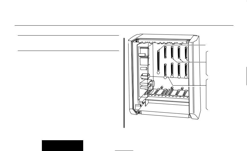
Where to Install the PCBs in a 28i System (Figure 2-1)
-01 92700
Maximum |
16 Trunks |
Configuration: |
20 Extensions (16 digital/8 analog) |
(All configurations are not available at the same time.)
The system’s universal architecture gives you flexibility when installing PCBs. You can install a PCB in any slot, provided you follow the guidelines in the chart below and keep within the limits of the load factor. The number of extensions must be limited to 20 due to the load factor for the system.
Item |
|
Description |
Location |
Max. |
24CPRU |
Central Processing Unit |
CPRU in Slot 1 |
1 |
|
|
|
|
|
|
8DSTU |
8 |
Digital Stations |
Slot 2 |
1 |
4ASTU |
4 Analog Stations |
Slots 2-5 |
2 * |
|
*Due to Load Factors, the 4ASTU PCB maximum is limited to 2. |
|
|||
4ATRU |
4 Analog Trunks |
Slots 2-5 |
4 |
|
2DIDU |
2 |
DID Trunks |
Slots 2-5 |
4 |
2BRIU |
2 |
BRI Circuits |
Slots 2-5 |
4 |
|
|
|
|
|
4PGDU |
4 |
Page/Door Box |
Slots 2-5 |
2 |
4DTDU |
Dial Tone Detection |
Slots 2-5 |
2 |
|
LAPBU |
LAPBU Unit |
Installs on CPRU PCB |
1 |
|
4CIDU |
Caller ID |
Installs on 4ATRU PCB |
4 |
|
4GSAU |
Ground Start |
Installs on 4ATRU PCB |
4 |
|
2.PCB Installation and Startup
CPRU with optional
|
|
|
LAPB PCB |
|
|
|
4 ASTU (Analog Station) |
|
|
|
or |
|
|
|
4 ATRU (Analog Trunk) |
|
|
|
or |
|
|
|
4 PDGU (Page/Door Box) |
|
|
|
or |
|
|
|
4 DTDU (Dial Tone Det.) |
|
|
|
or |
|
|
|
2 DIDU (DID) |
1 |
|
|
or |
|
|
2 BRIU (BRI Trunk) |
|
|
3 |
|
|
2 |
4 |
5 |
8 DSTU (Digital Station) or
4 ASTU (Analog Station) or
4 ATRU (Analog Trunk) or
4 PDGU (Page/Door Box) or
4 DTDU (Dial Tone Det.) or
2 DIDU (DID) or
2 BRIU (BRI Trunk)
Figure 2-1 PCB LOCATION
2-3

2.PCB Installation and Startup
PCB LOCATION
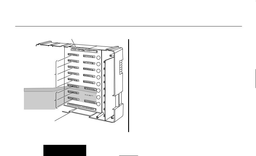
Where to Install the PCBs in a 124i System
(Figure 2-2)
Maximum Configuration: |
52 |
Trunks |
|
72 |
Extensions |
The system’s universal architecture gives you great flexibility when installing PCBs. You can install a PCB in any slot, provided you follow the guidelines in Figure 2-2 and the chart below.
Item |
Description |
Location |
Max. |
32CPRU |
Central Processing |
CPRU slot in Main |
1 |
|
Unit |
|
|
|
|
|
|
8DSTU |
8 Digital Stations |
Slots 1-3 in any |
3 per cabinet |
|
|
cabinet |
9 per system |
PRIU |
24 T1/PRI Trunks/ |
Slot 3 in any cabinet |
1 per cabinet |
|
Channels |
|
2 per system |
BRIU |
2 Two-Channel |
Slots 4-8 in any |
5 per cabinet |
|
BRI Circuits |
cabinet |
13 per system |
4ASTU |
4 Analog Stations |
Slots 1-8 in any |
8 per cabinet |
|
|
cabinet |
15 (with DSTU) |
|
|
|
per system |
|
|
|
16 (without DSTU) |
|
|
|
per system |
4ATRU |
4 Analog Trunks |
Slots 1-8 in any |
8 per cabinet |
|
|
cabinet |
13 per system |
2EMTU |
2 Tie Line Trunks |
Slots 4-8 in any |
5 per cabinet |
|
|
cabinet |
13 per system |
|
|
|
|
4PGDU |
4 Page/Door Box |
Slots 4-8 in any |
2 per system |
|
|
cabinet |
|
4DTDU |
Dial Tone Detection |
Slots 4-8 in any |
2 per system |
|
|
cabinet |
|
2DIDU |
2 DID Trunks |
Slots 4-8 in any |
5 per cabinet |
|
|
cabinet |
13 per system |
EXIFU |
Expansion Interface |
CPRU slot in |
1 per cabinet |
|
|
Expansion Cabinet |
2 per system |
|
|
||
EXCPRU |
CPRU Memory Exp. Installs on CPRU PCB 1 per system |
||
LAPBU |
LAPBU Unit |
Installs on CPRU PCB 1 per system |
|
4CIDU |
Caller ID Daughter |
Installs on 4ATRU |
8 per cabinet |
|
Board |
PCB |
13 per system |
|
|
|
OR |
4GSAU |
Ground Start |
Installs on 4ATRU |
8 per cabinet |
|
Daughter Board |
PCB |
13 per system |
2-4
PCB LOCATION
EXIFU-S1 PCB
|
|
EXIFU Ribbon Cables |
926 |
-42 |
|
|
|
|
2EMTU (Tie line) |
|
|
or |
|
|
2DIDU (DID Trunk) |
8 |
|
or |
|
|
4ASTU (Analog Station) |
7 |
|
or |
|
|
4ATRU (Analog Trunk) |
6 |
|
or |
|
|
4PGDU (Page/Door Box) |
|
|
or |
|
5 |
4DTDU (Dial Tone Det.) |
||
or |
|
4 |
BRIU (BRI Interface) |
||
or |
|
|
PRIU (TI/PRI) |
3 |
|
8DSTU (Digital Station) 
or
4ASTU (Analog Station) 
or
4ATRU (Analog Trunk) 
 2
2
1 |
32CPRU or
EXIFU (Expansion Interface)
Figure 2-2 PCB LOCATION |
2-5 |
2.PCB Installation and Startup

2.PCB Installation and Startup
INSTALLING PCBs
Advanced Feature (EXCPRU) (Figure 2-3)
The Advanced Feature (EXCPRU) Module is available only for the 124i system. It provides the system with:
●Automatic Call Distribution (ACD)
●ISDN Capability
●E&M Tie Lines
●T1
To install the Advanced Feature (EXCPRU) Module:
1.Plug the Advanced Feature Module into the headers on the right side of the CPRU PCB as shown in Figure 2-3.
2.Set the switch on the EXCPRU to position 1.
To upgrade the EXCPRU software, refer to page 2-35.
Remote Programming (LAPBU) Modules
(Figure 2-3 and 2-4)
You’ll need the Remote Programming Module if you want to use the PC Program with your system.
Advanced Feature
Remote Module (EXCPRU)
Programming
Module (LAPBU)
92001 |
- 40 |
Central Processor (CPRU) PCB |
|
|
Figure 2-3 124i EXCPRU AND LAPBU MODULES
2-6

INSTALLING PCBs
28i System (Figure 2-4)
The default settings for this card are: 9600 bps, Start bit=1, Stop bit=1, Parity=No, Character=8 bit. The software requires the baud rate be set to 9600 bps, so this item is fixed and can not be changed.
To install the Remote Programming (LAPBU) Module:
1.Plug the Remote Programming Module into the header on the CPRU PCB. The connector labeled CPRU on the LAPBU module plugs into the LAPBU connector on the CPRU.
2.Connect the DIN-to-9 pin RS-232 cable (P/N 92707) to the 28i’s LAPB card. Refer to Figure 2-4.
This card provides an 8-pin connector for the cable.
3.The opposite end of the cable is connected to the COM port on your PC.
Note that for the 28i PC Program, the modem initialize command must be entered as ATD#*#* (The 124i system requires an entry of ATDT#*#*.).
2.PCB Installation and Startup
DIN Connector for RS-232 Cable (Used for PC Programming)
RSCN
Baud Rate Setting Note: Baud rate must
be set at 9600.
CPRU
- 92700 02
Figure 2-4 28i LAPBU MODULE
2-7
2.PCB Installation and Startup
INSTALLING PCBs
8 CPRU PCB
8 DSTU PCB
-16 92700
LAPB PCB
66MI-50 Station Block
9 Pin RS-232 Cable
(P/N 92707) 25-Pair Cable
 9 Pin Male-to-25 Pin
Female Connector Station 
Cable

 25 Pin Male-to-Male Connector
(P/N 92268A)
|
625 |
|
Modem |
Modular |
|
Jack |
||
|
124i System
To install the Remote Programming (LAPBU) Module:
1.Plug the Remote Programming Module into the headers on the left side of the CPRU PCB as shown in Figure 2-3.
Figure 2-5 Connecting a Modem to LAPBU Module |
2-8 |

INSTALLING PCBs
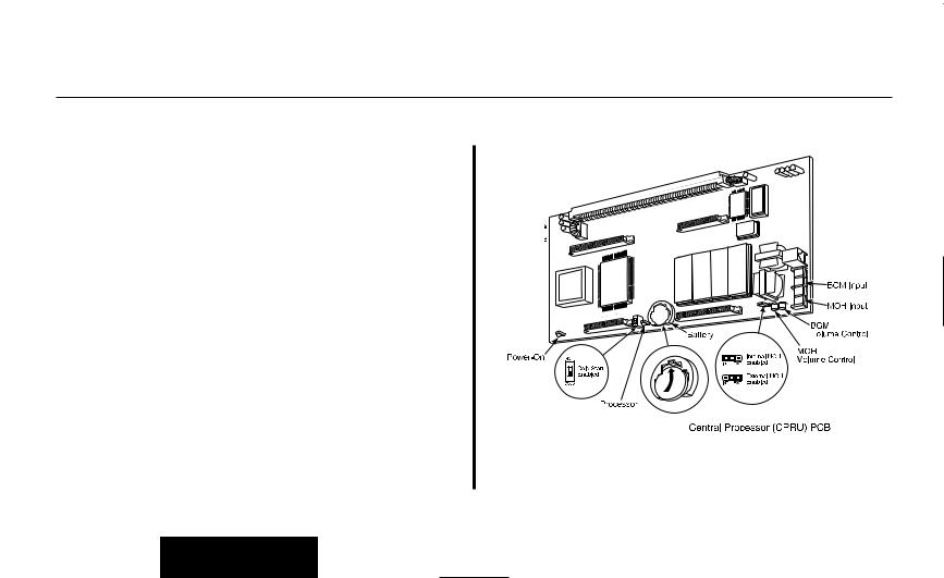
28i System: Central Processing Unit (CPRU)
PCB (Figure 2-6)
Plug the CPRU PCB into the CPRU slot (Slot 1) in the KSU. The CPRU provides:
●The system’s central processing, stored program and memory for the customer’s site-specific data.
●Mode switch for cold (default data) start on power-up.
●Reset switch to allow the system to be reset without powering down.
●Battery for short term (14 day) backup of the customer’s sitespecific data.
●Music on Hold jumper which allows you to select an external or internal source for Music on Hold.
●Volume Control for Music on Hold.
●DDK connectors for external Music on Hold/Background music source. The MOH music source can optionally be internal or connected to a 3-ACI Module. Refer to Music on Hold in the Software Manual for more.
●DDK connectors for eight digital telephones, VAU, 3-ACI, 3-DCI, or 2-OPX modules.
●An additional connector for the DIM-U diagnostic unit.
2.PCB Installation and Startup
LAPB
Connector
03 - 92700
Digital Stations 1-8

 External Music
on Hold Input
|
Battery |
MOH |
|
|
Power On |
DIMU |
Volume |
Internal |
|
Control |
MOH |
|||
Connector |
||||
|
|
Enabled |
||
Processor |
|
|||
|
External |
|||
|
|
|
||
|
Reset |
|
MOH |
|
|
Switch |
|
Enabled |
|
|
|
|
||
|
Cold |
|
|
|
|
Start |
|
|
|
Figure 2-6 CPRU PCB
2-9

2.PCB Installation and Startup
INSTALLING PCBs
To install the 28i system’s CPRU PCB:
1.Insert the battery into the battery clips.
2.Plug the CPRU into KSU CPRU slot (Slot 1).
3.When powering up, hold down the COLD switch on the CPRU.
This ensures that the system will load the default database on initial power-up.
On initial power up (with a cold startup), the system scans for station ports from the lowest slot to the highest slot, so the first 8 station ports on the 24CPRU are assigned extension numbers 301-308 automatically. The next station card that follows, no matter which slot it’s in, starts at extension 309.
Refer to Part 4, Installing Optional Equipment for instructions on installing Background Music and Music on Hold.
2-10
INSTALLING PCBs
124i System: Central Processing Unit (CPRU)
PCB (Figure 2-7)
Plug the CPRU PCB into the CPRU slot in the Main Cabinet. The CPRU provides:
●The system’s central processing, stored program and memory for the customer’s site-specific data.
●Mode switch for hot (customer data) or cold (default data) start on power-up.
●Battery for short term (14 day) backup of the customer’s site-specific data.
●Music on Hold jumper which allows you to select an external or internal source for Music on Hold.
●Volume Controls for Music on Hold and Background Music.
●DDK connectors for external Background Music or Music on Hold music sources. The MOH music source can optionally be internal or connected to a 3-ACI Module. Refer to Music on Hold in the Software Manual for more.
●An additional connector for the DIM-U diagnostic unit.
2.PCB Installation and Startup
Figure 2-7 CPRU PCB
2-11

2.PCB Installation and Startup
INSTALLING PCBs
To install the 124i system’s CPRU PCB:
1. Slide the Mode Switch to the Cold position.
This ensures that the system will load the default database on initial power-up. After initial power-up, you must change the Mode Switch to Hot.
2.Insert the battery into the battery clips.
3.Plug the CPRU into Main Cabinet CPRU slot.
Refer to Part 4, Installing Optional Equipment for instructions on installing Background Music and Music on Hold.
2-12

INSTALLING PCBs
Upgrading CPRU Firmware (Figure 2-8, 2-9)
Use these instructions when upgrading the Software EPROMs on the CPRU PCB. The new EPROMs in the upgrade kit are static-sensitive components. Be sure to follow the instructions below carefully. Failure to follow proper anti-static precautions could damage your new software.
To upgrade CPRU Firmware:
1.Attach a grounded wrist strap to your wrist and a grounded metal object (such as CEU ground).
2.If the system is currently powered up, unplug the system in the following order - main cabinet, first expansion cabinet, then the second expansion cabinet.
3.Lay the CPRU PCB on a flat, anti-static surface oriented as shown in Figure 2-8.
4.Using an IC puller, carefully remove the old EPROMs. Be careful not to rock the EPROMs or bend the pins during removal.
Remove all the EPROMs. Depending on your CPRU, there may be either two or four EPROMs.
5.Remove the new EPROMs from the anti-static sleeve. Save all the packaging.
2.PCB Installation and Startup
Grounded wrist strap
8 3
-
1 0 0 2 9
X7 X5 X6 X4
Figure 2-8 CPRU EPROM REMOVAL |
2-13 |

2.PCB Installation and Startup
INSTALLING PCBs
6.Following Figure 2-9, carefully install the new EPROMs.
●The EPROMs install in non-consecutive order. Be sure to install all four EPROMs.
● Pay careful attention to line up the notch in each EPROM with the notch in its socket.
● Do not bend any pins when plugging in the
EPROMs.
Grounded wrist strap
7. Reinstall the CPRU PCB. If the system has been previously installed, plug the system back in. Otherwise, continue with the installation.
8. Store old EPROMs in the anti-static sleeve.
Key
9. Insert the sleeve into the upgrade packaging and return to: Nitsuko America
4 Forest Parkway
Shelton, CT 06484
Attn: Technical Service
X7 X5 X6 X4
9 3
-
1 0 0 2 9
Figure 2-9 CPRU EPROM INSTALLATION |
2-14 |
|

INSTALLING PCBs
Digital Station (DSTU) PCB (Figure 2-10)
The Digital Station (DSTU) PCB provides DDK connectors for eight digital telephones, VAU, 3-ACI, 2-DCI, or 2-OPX modules.
To install a DSTU PCB:
1.28i: Plug a DSTU PCB into slot 2 in the KSU (1 DSTU PCB maximum per system).
124i: Plug DSTU PCBs into slots 1-3 in any installed cabinet (nine maximum).
2.Refer to Part 3: Installing Extensions and Trunks for cabling instructions.
On initial power-up (28i: hold down the Cold Start switch / 124i: CPRU Mode Switch set to Cold), the slot into which you plug a station PCB determines its associated extension numbers. The system scans for station PCBs from the lowest slot in the first cabinet (Main) to the high slot in the last cabinet (Expansion # 2). The first station PCB the system finds gets extension numbers 301-308. The next slot gets extension numbers 309-316, etc.
After initial power up (28i Hot Start without holding down any switch / 124i: CPRU Mode Switch set to Hot), any new station PCBs you plug in automatically add to the top of your exten-
2.PCB Installation and Startup
sion number list. For example, if your highest extension port is 324, any new station PCB you plug in will start with extension number 325. This is true regardless of the slot number used.
 Digital Station 8
 Digital Station 7
 Digital Station 6
 Digital Station 5
 Digital Station 4
 Digital Station 3
 Digital Station 2
 Digital Station 1
92001 |
- |
33 |
|
|
Digital Station (DSTU) PCB
Figure 2-10 DIGITAL STATION (DSTU) PCB
2-15

2.PCB Installation and Startup
INSTALLING PCBs
T1/PRI (PRIU) Interface PCB (Figure 2-11)
Note: For PRI, please consult with your Nitsuko
Representative for availability.
For T1 and ISDN Primary Rate Interface (PRI) applications, install a T1/PRI Interface PCB. This PCB has a single 24-channel circuit which can be configured for either T1 trunks or PRI. The T1/PRI PCB requires an Advanced Features Module (EXCPRU) and, for DTMF receivers, a Tone Detector (DTDU) PCB.
If set for T1, the T1/PRI PCB provides 24 trunks in a single slot. These trunks can be one of the following:
●Loop Start
●Ground Start
●DID
●Tie Lines
●ANI/DNIS Tie Lines
If set for PRI, each T1/PRI PCB provides 24 PRI (23 B&D) channels and supports the following PRI services:
●Basic PRI Call Control (BCC)
●Display of incoming caller’s name and number
●Routing based on the number the caller dials
●ISDN maintenance functions (e.g., In Service/Out of Service Messaging)
●Speech and 3.1 KHz audio
The T1 feature requires that the Base CPU version level must
be one of the following: |
|
|
|
|
||
3.3B |
3.3C |
3.4B |
3.4C |
4.3B |
4.3C |
4.6C |
7.0 |
7.1 |
7.2 |
7.3 |
8.0 or higher |
|
|
The version number should not be confused with the software revision. This version number will be stamped on the CPU circuit board. If the Base CPU version level is anything other than the levels shown above, the T1 will not operate correctly.
The T1/PRI Interface PCB also requires the CSU or CSU/DSU equipment and interconnecting cables listed below:
●T-Serve II CSU consisting of:
-T-Serve II CSU P/N 85950)
-T-Serve II Power Supply (P/N 85951)
-CSU/DSU RJ48-DB15 Cable (P/N 85953)
-T1/PRI Installation Cable (P/N 92067)
OR
2-16

INSTALLING PCBs
●Quad Datasmart DSU consisting of:
-Quad Datasmart DSU (P/N 85956)
-CSU/DSU DB15M-DB15F Cable (P/N 85952)
-CSU/DSU RJ48-DB15 Cable (P/N 85953)
-T1/PRI Installation Cable (P/N 92067)
The T1/PRI Interface PCB is designed to use the last available group of 24 consecutive trunks.
To install a T1/PRI Interface PCB:
1.Set the switches on the T1/PRI Interface PCB for either PRI Mode or T1 Mode.
2.Plug the T1/PRI Interface PCB into slot 3 of any cabinet (two maximum).
3.Connect the T1/PRI Installation Cable (P/N 92067) to the 4- wire DDK connector on the T1/PRI Interface PCB.
4.If connecting a CSU:
--Connect the opposite end of the T1/PRI cable to the DB-15 female connector (J4) on the CSU.
--Connect the DB-15 female connector on the RJ48-DB15 Cable (P/N 85953) to the DB-15 male connector (P2) on the CSU.
--Connect the opposite end of the RJ48-DB15 cable to the
2.PCB Installation and Startup
telco connection.
OR
4.If connecting a DSU:
--Connect the opposite end of the T1/PRI cable to the DB-15 female connector (TERMINAL) on the DSU.
--Connect the DB-15 female connector on the RJ48-DB15 Cable (P/N 85953) to the DB-15 male connector (NETWORK) on the DSU.
--Connect the opposite end of the RJ48-DB15 cable to the telco connection.
2-17
 Loading...