

Page 1

Digital
System
Hardware Manual for
Businesscom DS01
Page 2

CEU/Power Supply Site Requirements
Choose a central site for the MDF plywood backboard, within 7’ of a dedicated AC outlet and 25’ of earth ground.
Allow space for multiple CEU’s and power supplies. CEU’s
must be located within 3’ of each other. Power supplies
must be located within 6’ of the CEU and within 6’ of a
dedicated AC outlet. See Figure 1.
Allow space for telco and station connectors, all ancillary
equipment (ie; BGM/MOH source, voice mail, external paging equipment), and expansion. Refer to Nitsuko’s Standard
Practices Manual (P/N N2710STD01) for general environment and site specifications.
FIGURE 1
Mounting the CEU
1. Locate CEU mounting screws. Drill holes (2) in
backboard using a 1/8” drill bit. Refer to mounting
dimensions in Figure 2 (or use template, if installed).
2. Install CEU mounting screws (2) in holes. See Figure 2.
Use screw gauges to set proper screw depth.
(Screws & gauges are in plastic packet).
3. Hang CEU on mounting screws.
4. Drill lower CEU screw hole using a 1/8” drill bit.
See Figure 2. Install and tighten screw.
5. Ground each CEU using #12 AWG (or larger)
ground wire to earth ground.
Page 3

Mounting the Power Supply
1. Use power supply as template to locate mounting
screw holes.
2. Drill holes (2) in backboard using a 1/8” drill bit.
3. Locate power supply over holes.
4. Install screws (2-not provided).
FIGURE 2
Connecting the Power Supply to the CEU
1. Loop the power supply CEU power cord 3 times
through a ferrite bead (supplied in box).
2. Plug in the power supply CEU power cord into the
MAIN POWER connector on the CEU. See Figure 3.
Do not plug the power supply into an AC outlet.
1. CEU AND POWER SUPPLY
FIGURE 3
Power Strip/Surge Protector Connections
1. Plug the power supply cord into a power strip.
2. Plug the power strip into an AC surge protector.
3. Plug the surge protector into a dedicated AC outlet.
Powering Up
1. Turn the power switch on the power strip ON.
Refer to Power Up Procedure below (see Figure 4) for
proper sequence when not using a power strip.
2 CEU’s 3 CEU’s
1. Exp. CEU (SAUX) 1. Exp. CEU #2 (XAUX)
2. Exp. CEU (AUX) 2. Exp. CEU #1
3. Main CEU (AUX)
FIGURE 4
(SAUX)
Page 4

Installing CO and Station Modules
Power down to install or remove any module.
To install CO and Station Modules:
1. Line up the screw hole in the new module (i.e., the one you
are installing) with the pilot hole in the CEU base or existing
module. See Figure 5.
2. Place new module on CEU or existing module. If placing new
module on existing module, be sure to line up the ground lugs.
3. When placing new module on CEU, insert short screw through
new module and into CEU base. Tighten screw.
OR When placing new module on existing module, insert long
screw through new module and into CEU base. Tighten screw.
4. Insert the ribbon cable into the desired connector on the CEU:
(a) inside module's ribbon cable plugs into the outside
connector (b) outside module's ribbon cable plugs into the
inside connector.
01853L12A
FIGURE 5
CEU Position Extensions PCU Lines
Main 1 (inside) 300-311 368 1-4
Main 2 (outside) 312-323 369 5-8
Expansion #1 1 (inside) 324-335 370 9-12
Expansion #1 2 (outside) 336-347 371 13-16
Expansion #2 1 (inside) 348-359 17-20
Expansion #2 2 (outside) 360-371 21-24
#2 (outside)
#1 (inside)
#1 (inside)
FIGURE 6 FIGURE 7
4
3
2
1
8
7
01853L16
312-323
300-311
6
5
#2 (outside)
01853L15
Page 5

Installing AUX, SAUX, and XAUX Modules
A minimum of 7" clearance is required on the right side of a
CEU to install an AUX/SAUX/XAUX. Power down to install or
remove an AUX/SAUX/XAUX module or an 8-pin line cord.
Note: Initialization is not required to add an AUX to a system
running on CEU base software. The numbering plan, however,
changes automatically for lines, extensions, and ring groups.
To install an AUX, SAUX, and XAUX Module:
1. Remove cover plate.
2. Close CEU ejector tabs and insert the AUX into the CEU
upper and lower rails.
the CEU ejector tabs.
Push the module in until it clears
See Figure 8.
3. Open ejector tabs. Locate ribbon cable over connector.
4. Push in the module until it seats firmly into the CEU.
5. Push ribbon cable connector until firmly seated. The CEU
ejector tabs close. Tighten module screws (2).
Thumb Screw
01853L13
Ribbon
Thumb Screw
FIGURE 8
Cable
FIGURE 9
To install AUX, SAUX, and XAUX line cords:
1. Install line cords. Two CEU's: AUX-SAUX 6' line cord; three
CEU's: AUX-XAUX 3' line cord & XAUX-SAUX 6' line
cord. See Figure 10.
2. STATION, CO AND AUX/SAUX/XAUX MODULES
Note: AUX terminal program passwords: ONYXVSK, if AUX
FIGURE 10
is installed in a working system, but not initialized; DS01H, if
initialized with AUX installed.
Page 6

CO Line Installation
A modular line cord is required to connect Telco's RJ11C CO line
interface to a 4CO or 4CO\CND module. See Figure 7.
To connect a CO line to a 4CO or 4CO\CND module:
1. Plug one end of a modular line cord into a Telco RJ11C jack.
2. Insert the line cord's other end into the desired modular connector
on a 4CO or 4CO\CND module.
Installing Stations
Station connection for each extension requires two-pair twisted
station cable and a 4-conductor modular jack. See Figure 11.
Install a Dual ASI (any CEU) and DSS console (Main CEU only) to
an even-numbered port (except port 00). Leave the next-highest
adjacent odd-numbered port unterminated. See Figure 12.
Note: Single and Dual ASI's cannot be installed in ports 68-71.
To install a multibutton telephone, single port ASI, Electronic
Single Line telephone, or DSS console:
1. Install 625 modular jack within 6' feet of each extension.
2. Punch down 2-pair twisted station cable to desired extension
on cross-connect block. See Figure 13 for cutdown.
3. Terminate the other end of the station cable at each modular jack.
4. Plug the extension's line cord into the modular jack.
WHT-BLU
FIGURE 11
(RT) BLK
WHT-ORN
ORN-WHT
(RR) YEL
BLK
YEL
BLU-WHT
(TT) GRN
GRN
RED
(TR) RED
01853L17
Note: Refer to the Data Products Manual to install a Data Module.
Refer to the 12SCU/PCU Installation and Programming Instructions
when connecting a 500/2500 type device to a 12SCU/PCU module.
To connect the station block and cross-connect block:
1. Punch down 25-pair cable to station block.
2. Plug female connector end of 25-pair cable into Station Module.
3. Use x-connect to bridge station block to cross-connect block.
Note: DS01 telephones have electret-type handsets. For headset
operation, use Plantronics' Supra Star Mate (model # MH0503-1)
or an equivalent electret-compatible headset.
To install a Dual ASI:
1. Ground Dual ASI to earth ground using 14AWG ground wire.
2. Punch down 2-pair twisted station cable to an even-numbered
port on station block. Install bridging clips as shown in Figure 12.
3. Jumper to adjacent port's B pair using one-pair x-connect.
4. Terminate the other end of the station cable to a modular jack.
Page 7

To install a Dual ASI (cont’d.)
5. Plug one end of a 4-conductor line cord into the jack and the
other end into the Dual ASI's STA connector.
6. Plug in a line cord(s) from Dual ASI's OPX 1 and OPX 2 ports
to 2500-type device or Telco's OPX block.
FIGURE 12
3. STATION AND CO CABLING
CEU
25-PAIR CABLE
MAIN
CEU
(OUTSIDE)
312 (12)
313 (13)
314 (14)
315 (15)
316 (16)
317 (17)
318 (18)
319 (19)
320 (20)
321 (21)
322 (22)
323 (23)
EXP.
CEU 1
(INSIDE)
324 (24)
325 (25)
326 (26)
327 (27)
328 (28)
329 (29)
330 (30)
331 (31)
332 (32)
333 (33)
334 (34)
335 (35)
EXP.
CEU 1
(OUTSIDE)
336 (36)
337 (37)
338 (38)
339 (39)
340 (40)
341 (41)
342 (42)
343 (43)
344 (44)
345 (45)
346 (46)
347 (47)
EXP.
CEU 2
(INSIDE)
348 (48)
349 (49)
350 (50)
351 (51)
352 (52)
353 (53)
354 (54)
355 (55)
356 (56)
357 (57)
358 (58)
359 (59)
EXP.
CEU 2
(OUTSIDE)
360 (60)
361 (61)
362 (62)
363 (63)
364 (64)
365 (65)
366 (66)
367 (67)
368 (68)
369 (69)
370 (70)
371 (71)
FUNC.
N/C
N/C
TT
TR
RT
RR
TT
TR
RT
RR
TT
TR
RT
RR
TT
TR
RT
RR
TT
TR
RT
RR
TT
TR
RT
RR
TT
TR
RT
RR
TT
TR
RT
RR
TT
TR
RT
RR
TT
TR
RT
RR
TT
TR
RT
RR
TT
TR
RT
RR
N1853 -13
CONN
PIN
26
27
28
29
30
31
32
33
34
35
10
36
11
37
12
38
13
39
14
40
15
41
16
42
17
43
18
44
19
45
20
46
21
47
22
48
23
49
24
50
25
TERM.
1
1
2
3
2
4
5
3
6
7
4
8
9
10
5
11
12
6
13
14
7
15
16
8
17
18
9
19
20
21
22
23
24
25
26
27
28
29
30
31
32
33
34
35
36
37
38
39
40
41
42
43
44
45
46
47
48
49
50
WHT-BLU
BLU-WHT
WHT-ORN
ORN-WHT
WHT-GRN
GRN-WHT
WHT-BRN
BRN-WHT
WHT-SLT
SLT-WHT
RED-BLU
BLU-RED
RED-ORN
ORN-RED
RED-GRN
GRN-RED
RED-BRN
BRN-RED
RED-SLT
SLT-RED
BLK-BLU
BLU-BLK
BLK-ORN
ORN-BLK
BLK-GRN
GRN-BLK
BLK-BRN
BRN-BLK
BLK-SLT
SLT-BLK
YEL-BLU
BLU-YEL
YEL-ORN
ORN-YEL
YEL-GRN
GRN-YEL
YEL-BRN
BRN-YEL
YEL-SLT
SLT-YEL
VIO-BLU
BLU-VIO
VIO-ORN
ORN-VIO
VIO-GRN
GRN-VIO
VIO-BRN
BRN-VIO
VIO-SLT
SLT-VIO
(INSIDE)
300 (00)
301 (01)
302 (02)
303 (03)
304 (04)
305 (05)
306 (06)
307 (07)
308 (08)
309 (09)
310 (10)
311 (11)
MAIN
COLOR
BLOCK
CODE
FIGURE 13
Note: DS01 telephones supplied with this system are hearing-aid
compatible. Refer to Nitsuko America's Standard Practices Manual
for FCC Hearing-Aid Compatible application requirements.
Page 8

Installing a Music Source - Background Music or Music on Hold
A music source (radio, cassette, CD) connected to MOH terminals on
the Main CEU provides input for Background Music (BGM), or
Music on Hold (MOH), or both. MOH can be provided for CO calls only
or for CO and ICM calls.
BGM and/or MOH for ICM calls disables the Main CEU's 4th CO line
circuit. MOH for CO calls only does not disable a line circuit. Each
Expansion CEU can have its own MOH source or use the Main CEU's.
To connect a music source:
1. Install the music source per the manufacturer's instructions.
Caution: The music source output must not exceed the system's
music source input specifications. Some music sources may require
the installation of a matching transformer.
2. Connect the music source to the Main CEU's MOH terminals using
station or audio cable. Note: Bridge the music source output to an
Expansion CEU's MOH terminals, if required.
3. Program BGM and MOH per the Terminal Programming Manual
(E2 + QM) or Administrator's Guide (Programs 7 and 10).
4. Install RFI suppressor beads. (Refer to RFI bead installation)
5. Power up the music source. Activate BGM/MOH. Adjust the music
source for a distortion-free signal.
12121212
AUX MOH PA GND
FIGURE 14
Page 9
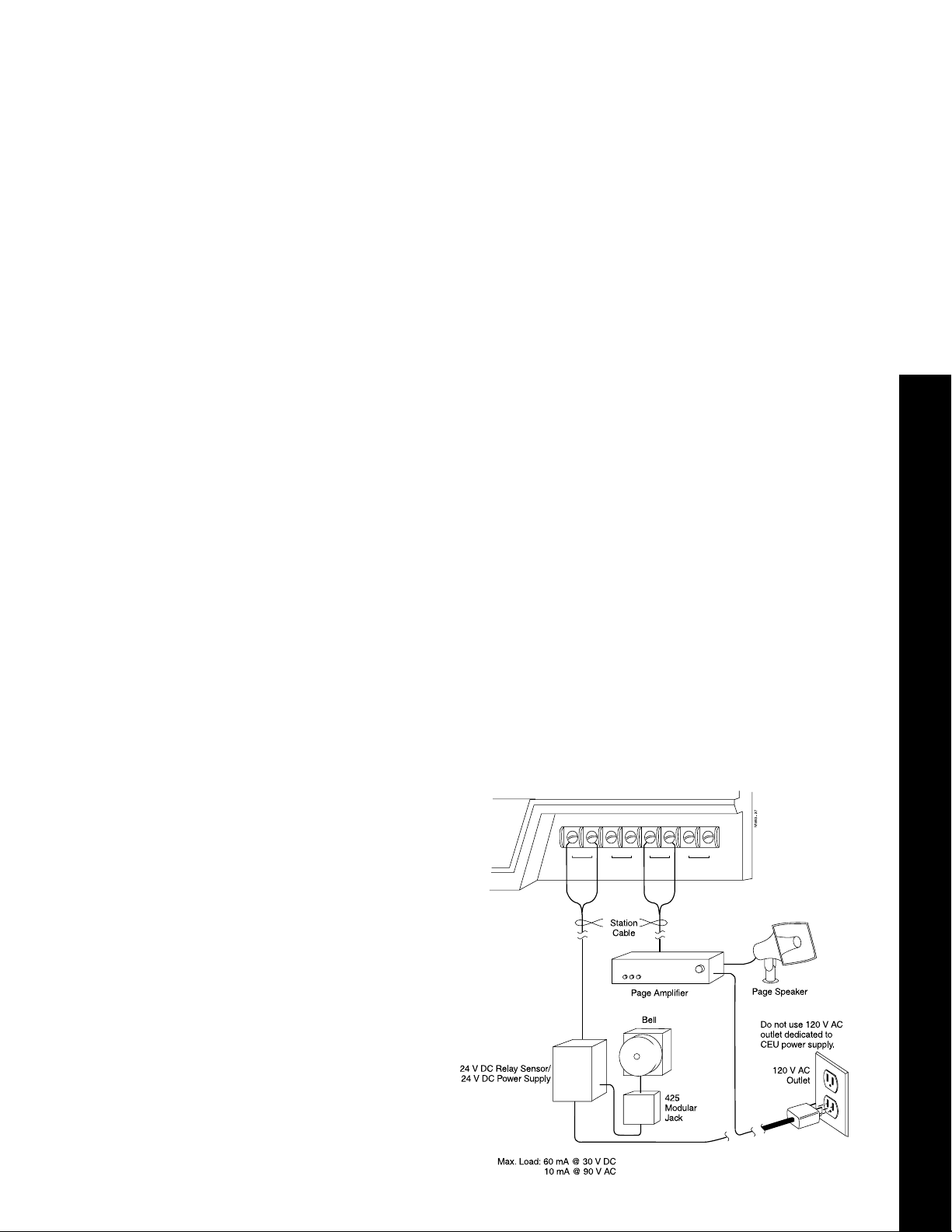
Installing External Paging or an External Relay Device (Loud Bell)
The PA terminals on the Main and Expansion #1 CEU's provide talk
paths for external paging systems. The Main CEU PA terminals are for
external zone 1. The Expansion #1 CEU PA terminals are for external
zone 2. A paging system receives internal or external pages, or Night
Audible ringing, or both. Each page system disables a line circuit: Main
CEU - line 4; Expansion CEU #1 - line 12. The AUX terminals on the
Main and Expansion #1 CEU's provide a dry contact ring relay. The relay
can be used for a loud bell, a door striker, etc.
To connect an external paging system or relay sensor:
1. Install the paging system/relay sensor per manufacturer's
instructions. Caution: The paging system must not exceed the
system's paging input specifications. Some paging systems may
require the installation of a matching transformer. See Figure 15.
2. Connect the paging system to the PA terminals or the relay sensor to
the AUX terminals using station or audio cable.
3. Program External Paging/Relay Owner per the Terminal
Programming Manual (E2 + QM) or Administrator's Guide
(Programs 7 + 10).
4. Install RFI suppressor beads. (Refer to RFI bead installation).
5. Power up the paging system. Make page. Adjust the paging
system for a distortion-free signal. Check relay sensor by dialing the
relay owner extension number.
4. BGM/MOH, PAGING, AND LOUD BELL
12121212
AUX MOH PA GND
FIGURE 15
Page 10

Installing a Programming Terminal, SMDR printer, PC, or Modem
The AUX Module DCE 9-pin male RS-232 serial port interfaces a programming terminal, SMDR printer, PC (DTE), or a modem (DCE). A DB9-DB25
adaptor is required. DTE connection requires a straight-thru RS-232 cable.
DCE connection requires a DCE-DCE adaptor and a straight-thru RS-232
cable OR a null modem cable.
Note: A null modem or RS-232 cable requires DB25 connectors. Gender of
the DB25 connectors depend on the adaptor and the terminal, SMDR
printer, or PC's serial port.
To connect a DTE programming terminal, SMDR printer, or PC:
1. Plug a DB9-DB25 adaptor into the AUX port. The DB9 must be female.
2. Connect one end of the RS-232 cable to the adaptor's DB25 connector.
3. Connect the other end of the RS-232 cable to the serial port on the
programming terminal, SMDR printer, or PC. See Figure 16.
Note: When connecting a laptop PC equipped with 9-pin serial port, use
a straight-thru 9-pin RS-232 cable.
1
2
3
4
5
6
7
8
9
FIGURE 16
Page 11

Installing a Modem
You can connect a modem to the AUX Module serial port for remote programming and diagnostics.
To connect the AUX Module to a modem (DCE):
1. Plug a DB9-DB25 adaptor into the AUX port. The DB9 must be female.
2. Connect one end of the RS-232 cable to the adaptor's DB25 connector.
OR
Connect a 25-pin null-modem cable into the adaptor's DB25 connector.
3. Connect the other end of the RS-232 cable to a DCE-DCE adaptor.
Skip Step #3 when using a null modem cable.
4. Connect the other end of the DCE-DCE adaptor or null modem cable to the
modem's serial port. See Figure 17.
5. SMDR AND TERMINAL PROGRAMMING
FIGURE 17
To set the AUX serial port baud
rate (from extension 300/port 00):
1. Lift handset + press ICM.
2. Dial: #, 0.
3. Dial a digit to select baud rate:
0 = 300, 1 = 1200, 2 = 2400
3 = 4800, 4 = 9600, 5 = 19.2K
DATA FORMAT
Data bits = 8
Stop bits = 1
Baud rate =1200
Parity = none
Page 12

Installing Battery Backup (Optional)
One Valcom VPB-260 battery backup unit provides a CEU with short-term power
(2 hours - max.) during a commercial AC power failure. One per CEU max.
To install the VPB-260:
1. Mount the VPB-260 on the MDF backboard within 3' of the CEU. Follow
manufacturer’s mounting instructions.
2. Power down the CEU’s power supply.
3. Plug the VPB-260 3-pin female plug into the 3-pin male AUX POWER
connector on the CEU.
4. Plug the VPB-260 power cord into a dedicated 120VAC outlet.
01853L22
To Power Supply
123
+ 12 V DC
common
- 12 V DC
Do not use the
outlet dedicated to
CEU power supply.
120 V AC
Outlet
3' max.
Note: Follow manufacturer's
instructions when connecting
the battery backup unit.
Battery
Backup
FIGURE 18
Page 13

Installing Power Failure (PF) Telephones (Optional)
The first circuit in each 4CO or 4CO/CND module (1/5, 9/13, 17/21) provides a PF
cut-through relay. Each PF relay, corresponding modular jacks, and cross-connections redirect a CO line to a 500/2500 single line telephone for full incoming\outgoing
operation during an AC power outage.
To install a PF telephone:
1. Install 3 modular jacks for each line requiring PF operation. Label jacks CO Line,
PF Line, and PF Telephone. (The PF Line jack must be 6-conductor).
2. Connect GRN/RED from the CO Line jack to GRN/RED of the PF Line jack using
one-pair x-connect cable. See Figure 19.
3. Connect WHT/BLU from the PF Line jack to GRN/RED of the PF Telephone jack
using one-pair x-connect cable.
4. Connect Telco's RJ11C to the Line jack using a standard line cord.
5. Connect the PF Line jack to the 4CO module's modular connector (lines 1/5, 9/13,
17/21) using a 6-conductor line cord.
6. Connect a PF telephone to the PF Telephone jack with a standard line cord.
To test power failure cut-through at a PF telephone:
1. Power down the system.
2. Lift the handset on the PF telephone. (You should hear dial tone.) Place a call
from the PF telephone.
6. BATTERY BACKUP AND POWER FAILURE TELEPHONES
RED
GRN
BLU
N1853 - 32
BLK YEL
4 3 2 1 PFT
GRN
WHT
BLU
BLK YEL
4CO
RED
GRN
BLU
WHT
BLK YEL
RED
WHT
FIGURE 19
Page 14

Installing the Digital Door Box
The Digital Door Box (P/N 88545) provides one-button signaling and intercom. Up to four
Digital Door Boxes can be installed at extensions 310, 311, 322, and 323 only. Each Digital
Door Box provides a distinctive chime signal. Any keyset can receive any/all chime signals.
To install the Digital Door Box:
1. Snap open the Door Box case.
2. Punch down one end of a two-pair twisted station cable on the extension block as shown
below.
Digital Door Boxes have the same cabling requirements as Electronic Single Line
telephones.
3. Run the station cable through the hole in the back of the Door Box.
When wall mounting,
use the two holes in the base of the door box for the mounting screws.
4. Strip the free conductors back about 1/2 inch and connect to the Door Box terminals as
shown in Figure 20.
5. Snap the Door Box cover onto the base.
6. In E-Extensions, E3-Class of Service (or Program 18I option COS from the
administrator’s telephone), assign each Door Box extension Class of Service 28. In
QV- Peripheral Ports, Door Box Alert Time (or Program 18I option DB from the
administrator’s telephone), set which extensions should receive Door Box Chimes.
Refer to your Software Administrators Manual for additional programming details.
1853 - 30A
FIGURE 20
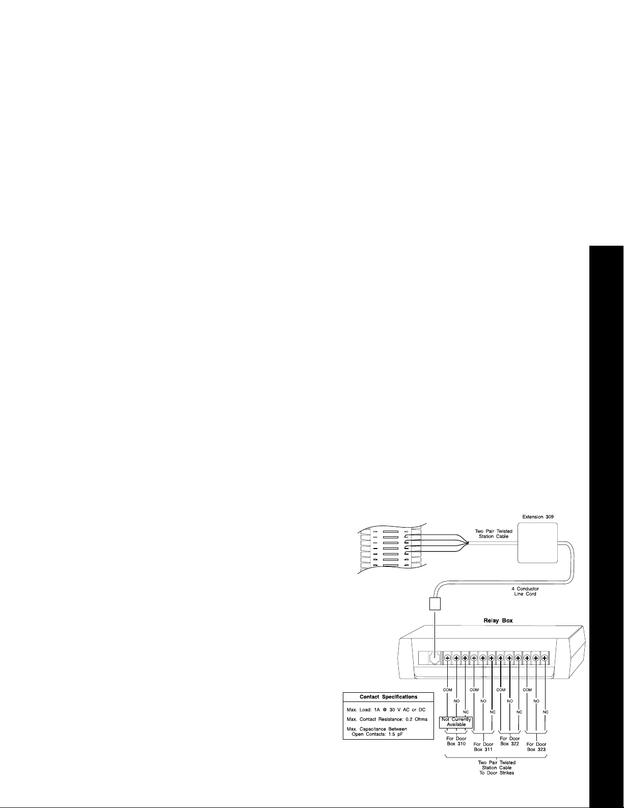
Installing the Relay Box
The Relay Box (P/N 88546) provides three normally-open relays which typically are used to
activate an electric strike door-unlock mechanism for an entrance door equipped with a
Digital Door Box. After responding to a Door Box chime signal, the user activates the relay
(opening a door) by pressing the FTR button on the telephone dialpad.
To Install the Relay Box:
1. Punch down a 4-conductor station cable to extension 309.
2. Terminate the other end of the cable to a modular jack. See Figure 21.
3. Plug in a 4-conductor line cord into the modular jack. Plug the other end into the
Relay Box.
Page 15
Operation
To activate relays from a multibutton set:
1. Lift handset to answer the Door Box chimes.
If you have a Door Box Hotline or Call Coverage key, you can press it
instead.
OR
Place call to Door Box.
You can press Intercom and dial the Door Box extension number. You can
also press your Door Box Hotline or Call Coverage key (if you have one).
2. Talk to the visitor at the door.
3. Press and hold FTR.
The relay activates as long as you hold down the FTR key
(up to 60 seconds).
4. Hang up when you are through.
To activate relays from a single line set:
1. Lift handset to answer the Door Box chimes.
OR
Place call to Door Box (i.e., dial Door Box extension number).
2. Talk to the visitor at the door.
3. Dial *.
Do not hold down the * key. The relay activates for six seconds and then
automatically releases.
4. Hang up when you are through.
Programming Notes: At
extension 309, set E2Circuit Type to X. Set E3Class of Service to 28.
At each extension that
37
38
39
N1853 - 31
40
TT
TR
RT
RR
White/Blue
Blue/White
White/Orange
Orange/White
should activate the strike: In
QV-Peripheral Ports (Alert
Programming),
enable Alert for each Door
Box. If an extension
receives chimes, it can activate the associated
Relay Box strike.
7. DOOR BOX AND RELAY BOX
FIGURE 21
Page 16

CEU Specifications: Lines Stations
Main CEU 8 24
Expansion CEU #1 8 24
Expansion CEU #2 8 24
Total 24 72
System Capacity:
Power Failure Cut-Through Circuit 1 per CO Module
Talk Timeslots (Intercom/lines) Non-blocking
DTMF Tone Duration (manual dial) 256 ms on/128 ms off
DTMF Tone Duration (speed dial) 128 ms on/128 ms off
Internal Page Zones 7 (and all-call)
External Page Zones 1 output per Main & Exp.CEU #1
External Control Relay Circuits 1 set of contacts per Main & Exp. CEU #1
Electrical Specifications:
AC Input:
115 V AC +/- 10% @ 57-63 Hz, Dedicated 15 A circuit.
Grounding Requirements:
Copper wire, continuous, No. 14 AWG, or larger.
Power Requirements:
75-100VA maximum (per CEU) - Refer to power supply label.
Heat Dissipation:
256 BTU per CEU
AUX Relay Contact Rating: External Zone Paging:
Max. Load: 60 mA @ 30 V DC Output Impedance: 600 OHMS
10 mA @ 90 V AC Max. Output: +3 dBm
Maximum Initial Contact Resistance:
50 m OHMS
Background Music\Music on Hold:
Input Impedance: 100 K OHMS
Maximum Input: -10 dBm
Cable Requirements: From CEU to Keysets or ASI:
Four-conductor (two-pair twisted station cable)
1,500 feet w/No. 26 AWG
2,000 feet w/No. 24 AWG
2,500 feet w/No. 22 AWG
From ASI to connected OPX device:
100 feet using 22 AWG four-conductor.
Use 25-pair cables with Type 57 female connectors to connect to Station Modules.
Use four conductor modular line cords to connect to CO Modules.
Use multiconductor "riser cables" to an Intermediate Distribution Frame (IDF)
when required.
Page 17

Mechanical Specifications
Width Height Depth Weight
CEU 14 5/16" 9 1/4" 3" 3 lb, 11 oz
39.2 cm 23.7 cm 7.6 cm 1.7 kg
CO Module 6 3/4" 6 3/4" 1 1/2" 1 lb
17.1 cm 17.1 cm 3.8 cm .5 kg
Station Module 6 3/4" 6 3/4" 1 1/2" 1 lb
17.1 cm 17.1 cm 3.8 cm .7 kg
Power Supply 2 13/16" 5" 2 3/4" 3 lbs
7.2 cm 12.7 cm 7.0 cm 1.4 kg
Keysets 3 1/2" 7 1/2" 10 1/8" 2.7 lb
8.9 cm 19.1 cm 25.8 cm 1.3 kg
NOTE: Weight of CEU is with modules not installed.
Environmental Specifications
Refer to the Standard Practices Manual (P/N N2710STD01).
FCC Registration Information
Model: DS01
Manufacturer: Nitsuko America
Load number (DOC) 20
FCC Part 15 Registration: Class A
Sample FCC Registration Number: 1ZDTHA-65325-MF-E
8. SPECIFICATIONS
Type of Interface Connector Code Code
2-Wire Loop RJ11C 2.5B 02LS2
Load Factor Table
Item Load Factor* Circuit Type Notes
Display keyset 1 02 1 port, auto-ID
DSS console 2 06 2 port, auto-ID
Dual-ASI 3 51 2 port, no auto-ID
Standard keyset 1 01 1 port, auto-ID
ASI 1 51 1 port, no auto-ID
ESL 1 00 1 port, auto-ID
Door Box 1 X 310/311/322/323 only
Relay Box 1 X Installed at 309 only
Data Module 1 01 1 port, no auto-ID
Total load per CEU not to exceed 24.
*
USOC Jack REN/Service Interface
Relay for 310 cannot be used
Facility
Page 18

Description Part Number
Common Equipment
Power Supply .............................................................................................................60001
CEU - (includes: 1 Common Equipment Unit base + 1 - 60001 + RFI beads,
no modules)................................................................................................................88600
4x12 Kit (no phones): .................................................................................................88601
1 - 88600 (includes: 1 - CEU + 1 - 60001 + RFI beads)
1 - 88511 4 CO Module, 1 - 88521 12 Station Module (digital)
4x12 Kit (8 phones): ...................................................................................................88691
1 - 88601 (includes: 1 - 88600 + 88511 + 88521 + RFI beads)
1 - 88663 HF Display Telephone, 7 - 88661 HF Telephones
12x36 Kit (10 phones): ...............................................................................................88692
2 - 88601 (includes: 1 - 88600 + 88511 + 88521 + RFI beads)
1 - 88511 4 CO Module
1 - 88521 12 Station Module
1 - 88625 AUX Module
1 - 88529 SAUX Module (includes: 1 - 88587 6' 8-conductor cable)
2 - 88663 HF Display Telephones
8 - 88661 HF Telephones
Modules
4 CO Module ..............................................................................................................88511
4 CO Caller ID Module ...............................................................................................88512
12 Station Module (digital)..........................................................................................88521
AUX Module ...............................................................................................................88625
SAUX Module (includes: 1 - 88587 6' 8-conductor cable)..........................................88529
XAUX Expansion AUX Module (includes: 1 - 88588 3' 8-conductor cable)................88526
12SCU/VMU Voice Module Unit (12 stations + 3 VMU ports)....................................88522
12SCU/PCU Peripheral Control Unit Module (12 stations + 2 - 2500 circuits)...........88530
AUX/SAUX Kit: ...........................................................................................................88695
1 - 88625 AUX Module
2 - 88529 SAUX Module (includes: 1 - 88587 6' 8-conductor cable)
Software
CEU base software upgrade - latest release - (2 IC chips)........................................88608
AUX module software upgrade - latest release - (2 IC chips) ....................................88628
SAUX/XAUX module software upgrade - latest release (1 IC chip)...........................88589
Upload/Download Program - (1 floppy disk)...............................................................88217
Station Equipment
16 Button Non-HF Telephone (Taupe).......................................................................88660
16 Button HF Telephone (Taupe)...............................................................................88661
16 Button HF Display Telephone (Taupe)..................................................................88663
16 Button Non-HF Telephone (Graphite) ...................................................................88670
16 Button HF Dual LED Telephone (Graphite)...........................................................88671
16 Button HF Display Dual LED Telephone (Graphite)..............................................88673
Digital Single Line Telephone (Taupe).......................................................................88650
Digital Single Line Telephone (Graphite)....................................................................88676
Page 19

CEU/Power Supply Site Requirements
Choose a central site for the MDF plywood backboard, within 7’ of a dedicated AC outlet and 25’ of earth ground.
Allow space for multiple CEU’s and power supplies. CEU’s
must be located within 3’ of each other. Power supplies
must be located within 6’ of the CEU and within 6’ of a
dedicated AC outlet. See Figure 1.
Allow space for telco and station connectors, all ancillary
equipment (ie; BGM/MOH source, voice mail, external paging equipment), and expansion. Refer to Nitsuko’s Standard
Practices Manual (P/N N2710STD01) for general environment and site specifications.
FIGURE 1
Mounting the CEU
1. Locate CEU mounting screws. Drill holes (2) in
backboard using a 1/8” drill bit. Refer to mounting
dimensions in Figure 2 (or use template, if installed).
2. Install CEU mounting screws (2) in holes. See Figure 2.
Use screw gauges to set proper screw depth.
(Screws & gauges are in plastic packet).
3. Hang CEU on mounting screws.
4. Drill lower CEU screw hole using a 1/8” drill bit.
See Figure 2. Install and tighten screw.
5. Ground each CEU using #12 AWG (or larger)
ground wire to earth ground.
Description Part Number
Other Station Equipment
DSS Console (Taupe) ................................................................................................88655
DSS Console (Graphite).............................................................................................88675
Digital Door Box..........................................................................................................88545
Relay Box ...................................................................................................................88546
ASI - Analog Station Interface (single port w/DTMF receiver)....................................88749
Dual Port ASI (dual port w/DTMF receivers) ..............................................................88750
Wall Mount Kit (Taupe)...............................................................................................88679
Wall Mount Kit (Dark Gray).........................................................................................88779
Wall Mount Hanger.....................................................................................................88680
Data Products
Data Module ...............................................................................................................88400
Dataport PCB .............................................................................................................88460
Modem Pooling PCB ..................................................................................................88465
Mini Data Unit.............................................................................................................89408
Mini Data Unit Power Supply......................................................................................89409
DCE-DCE Adaptor......................................................................................................89079
Replacement Parts
K1 Handset (Taupe)...................................................................................................88685
K1H Handset (Dark Gray) ..........................................................................................88775
Handset Cord (6 foot)..............................................................................................88685-6
Handset Cord (9 foot)..............................................................................................88685-9
Handset Cord (13 foot)..........................................................................................88685-13
Line Cord (7 foot) ....................................................................................................88686-7
Line Cord (14 foot) ................................................................................................88686-14
Line Cord (25 foot) ................................................................................................88686-25
8-conductor 6' cable (AUX-SAUX w/2CEU's or SAUX-XAUX w/3 CEU's).................88587
8-conductor 3' cable (AUX-XAUX w/3 CEU's)............................................................88588
Installation Equipment
Plywood Backboard
66M1-50 connecting block(s)
25-pair cable(s)
22/24 AWG 4-conductor twisted-pair station cable
Cross-connect wire
Bridging clips
Modular jack (1 per station)
Modular line cords (1 per CO line)
Ground wire (1 per CEU)
RJ11C Telco interface (1 per CO line)
AC surge protector (1 per CEU)
1
Item not supplied by Nitsuko America.
1
1
1
1
1
1
1
1
1
1
1
9. PARTS LIST
Page 20

Description Part Number
Other Station Equipment
DSS Console (Taupe) ................................................................................................88655
DSS Console (Graphite).............................................................................................88675
Digital Door Box..........................................................................................................88545
Relay Box ...................................................................................................................88546
ASI - Analog Station Interface (single port w/DTMF receiver)....................................88749
Dual Port ASI (dual port w/DTMF receivers) ..............................................................88750
Wall Mount Kit (Taupe)...............................................................................................88679
Wall Mount Kit (Dark Gray).........................................................................................88779
Wall Mount Hanger.....................................................................................................88680
Data Products
Data Module ...............................................................................................................88400
Dataport PCB .............................................................................................................88460
Modem Pooling PCB ..................................................................................................88465
Mini Data Unit.............................................................................................................89408
Mini Data Unit Power Supply......................................................................................89409
DCE-DCE Adaptor......................................................................................................89079
Replacement Parts
K1 Handset (Taupe)...................................................................................................88685
K1H Handset (Dark Gray) ..........................................................................................88775
Handset Cord (6 foot)..............................................................................................88685-6
Handset Cord (9 foot)..............................................................................................88685-9
Handset Cord (13 foot)..........................................................................................88685-13
Line Cord (7 foot) ....................................................................................................88686-7
Line Cord (14 foot) ................................................................................................88686-14
Line Cord (25 foot) ................................................................................................88686-25
8-conductor 6' cable (AUX-SAUX w/2CEU's or SAUX-XAUX w/3 CEU's).................88587
8-conductor 3' cable (AUX-XAUX w/3 CEU's)............................................................88588
Installation Equipment
Plywood Backboard
66M1-50 connecting block(s)
25-pair cable(s)
22/24 AWG 4-conductor twisted-pair station cable
Cross-connect wire
Bridging clips
Modular jack (1 per station)
Modular line cords (1 per CO line)
Ground wire (1 per CEU)
RJ11C Telco interface (1 per CO line)
AC surge protector (1 per CEU)
1
1
1
1
1
1
1
1
1
1
1
9. PARTS LIST
1
Item not supplied by Nitsuko America.
Page 21

This manual has been developed by Nitsuko America. It is intended for the use of its customers
and service personnel, and should be read in its entirety before attempting to install or program
the system. Nothing contained in this manual shall be deemed to be, and this manual does not
constitute, a warranty of, or representation with respect to, any of the equipment covered. This
manual is subject to change without notice and Nitsuko America has no obligation to provide any
updates or corrections to this manual. Further, Nitsuko America also reserves the right, without
prior notice, to make changes in equipment design or components as it deems appropriate. No
representation is made that this manual is complete or accurate in all respects and Nitsuko
America shall not be liable for any errors or omissions. In no event shall Nitsuko America be
liable for any incidental or consequential damages in connection with the use of this manual.
This document contains proprietary information that is protected by copyright. All rights are
reserved. No part of this document may be photocopied or reproduced without prior written
consent of Nitsuko America.
© 1994 by Nitsuko America. All Rights Reserved.
4 Forest Parkway, Shelton, CT 06484
TEL: 203-926-5400 FAX: 203-929-0535
Part No. N1870INS02
Issue 1-0
Printed in U.S.A. (185)
July 1994
 Loading...