

Page 1

ELECTRICAL SYSTEM
GI
MA
CONTENTS
PRECAUTIONS ...............................................................4
Supplemental Restraint System (SRS) ″AIR
BAG″............................................................................4
Wiring Diagrams and Trouble Diagnosis.....................4
HARNESS CONNECTOR................................................5
Description...................................................................5
STANDARDIZED RELAY................................................7
Description...................................................................7
POWER SUPPLY ROUTING...........................................9
Schematic..................................................................10
Wiring Diagram - POWER - ......................................12
Inspection...................................................................19
GROUND........................................................................20
Ground Distribution....................................................20
COMBINATION SWITCH ..............................................29
Check.........................................................................29
Replacement..............................................................30
STEERING SWITCH......................................................31
Check.........................................................................31
HEADLAMP (FOR USA)...............................................32
Component Parts and Harness Connector
Location .....................................................................32
System Description....................................................32
Wiring Diagram - H/LAMP -.......................................34
Trouble Diagnoses.....................................................36
Bulb Replacement .....................................................44
Aiming Adjustment.....................................................44
HEADLAMP (FOR CANADA) - DAYTIME LIGHT
SYSTEM - ......................................................................46
Component Parts and Harness Connector
Location .....................................................................46
System Description....................................................46
Wiring Diagram - DTRL -...........................................49
Trouble Diagnoses.....................................................51
Bulb Replacement .....................................................52
Aiming Adjustment.....................................................52
PARKING, LICENSE AND TAIL LAMPS .....................53
Wiring Diagram - TAIL/L -..........................................53
STOP LAMP ..................................................................54
SECTION
Wiring Diagram - STOP/L - .......................................54
BACK-UP LAMP............................................................55
Wiring Diagram - BACK/L -.......................................55
CORNERING LAMP......................................................56
System Description....................................................56
Wiring Diagram - CORNER - ....................................57
TURN SIGNAL AND HAZARD WARNING LAMPS.....58
System Description....................................................58
Wiring Diagram - TURN -..........................................59
Trouble Diagnoses.....................................................61
Electrical Components Inspection.............................61
TRAILER TOW...............................................................62
System Description....................................................62
Wiring Diagram - T/TOW -.........................................63
Trouble Diagnoses.....................................................64
ILLUMINATION..............................................................65
System Description....................................................65
Schematic..................................................................67
Wiring Diagram - ILL -...............................................68
INTERIOR ROOM LAMP...............................................72
System Description....................................................72
Schematic..................................................................74
Wiring Diagram - INT/L -...........................................75
Trouble Diagnoses.....................................................78
METERS AND GAUGES...............................................80
Component Parts and Harness Connector
Location .....................................................................80
System Description....................................................80
Combination Meter ....................................................82
Wiring Diagram - METER - .......................................84
Trouble Diagnoses.....................................................85
Electrical Component Inspection...............................90
WARNING LAMPS........................................................92
System Description....................................................92
Schematic..................................................................94
Wiring Diagram - WARN -.........................................95
Electrical Component Inspection...............................99
WARNING CHIME.......................................................100
EL
EM
LC
EC
FE
AT
AX
SU
BR
ST
RS
BT
HA
SC
IDX
Page 2

CONTENTS (Cont’d)
Component Parts and Harness Connector
Location ...................................................................100
System Description..................................................100
Wiring Diagram - CHIME - ......................................102
Trouble Diagnoses...................................................103
FRONT WIPER AND WASHER..................................108
System Description..................................................108
Wiring Diagram - WIPER -......................................109
Trouble Diagnoses...................................................110
Removal and Installation.........................................110
Washer Nozzle Adjustment ..................................... 111
REAR WIPER AND WASHER....................................113
System Description/Except for Glass Hatch
Model.......................................................................113
Wiring Diagram - WIP/R - /Except for Glass
Hatch Model.............................................................114
System Description/For Glass Hatch Model ...........115
Wiring Diagram - WIP/R - /For Glass Hatch
Model.......................................................................116
Removal and Installation.........................................117
Washer Fluid and Check Valve...............................118
HORN...........................................................................119
Wiring Diagram - HORN - .......................................119
CIGARETTE LIGHTER................................................120
Wiring Diagram - CIGAR -.......................................120
REAR WINDOW DEFOGGER.....................................121
Component Parts and Harness Connector
Location ...................................................................121
System Description..................................................121
Wiring Diagram - DEF -...........................................123
Trouble Diagnoses...................................................124
Electrical Components Inspection...........................126
Filament Check........................................................126
Filament Repair .......................................................127
AUDIO..........................................................................129
System Description..................................................129
Schematic................................................................130
Wiring Diagram - AUDIO -.......................................131
Trouble Diagnoses...................................................134
AUDIO ANTENNA.......................................................141
Location of Antenna.................................................141
Removal and Installation.........................................141
POWER SUNROOF.....................................................142
System Description..................................................142
Wiring Diagram - SROOF -.....................................143
POWER DOOR MIRROR............................................144
Wiring Diagram - MIRROR - /Without Automatic
Drive Positioner .......................................................144
HEATED MIRROR.......................................................145
Wiring Diagram - H/MIRR -.....................................145
AUTOMATIC DRIVE POSITIONER ............................146
Component Parts and Harness Connector
Location ...................................................................146
System Description..................................................146
Schematic................................................................149
Wiring Diagram - AUT/DP -.....................................150
Trouble Diagnosis....................................................155
POWER SEAT.............................................................183
Wiring Diagram - SEAT -.........................................183
AUTOMATIC SPEED CONTROL DEVICE (ASCD)...185
Components Parts and Harness Connector
Location ...................................................................185
System Description..................................................186
Schematic................................................................188
Wiring Diagram - ASCD - ........................................189
Fail-safe System......................................................194
Trouble Diagnoses...................................................195
Electrical Component Inspection.............................206
ASCD Wire Adjustment ...........................................208
POWER WINDOW.......................................................209
System Description..................................................209
Wiring Diagram - WINDOW -..................................211
Trouble Diagnoses...................................................213
POWER DOOR LOCK.................................................214
Component Parts and Harness Connector
Location ...................................................................214
System Description..................................................214
Schematic................................................................216
Wiring Diagram - D/LOCK -.....................................217
Trouble Diagnosis....................................................222
MULTI-REMOTE CONTROL SYSTEM.......................234
Component Parts and Harness Connector
Location ...................................................................234
System Description..................................................234
Schematic................................................................237
Wiring Diagram - MULTI - .......................................238
Trouble Diagnoses...................................................242
ID Code Entry Procedure........................................251
Remote Controller Battery Replacement.................252
THEFT WARNING SYSTEM.......................................253
Component Parts and Harness Connector
Location ...................................................................253
System Description..................................................255
Schematic................................................................258
Wiring Diagram - THEFT -.......................................259
Trouble Diagnoses...................................................266
SMART ENTRANCE CONTROL UNIT.......................278
Description...............................................................278
Schematic................................................................280
Smart Entrance Control Unit Inspection Table........282
INTEGRATED HOMELINK TRANSMITTER...............284
Wiring Diagram - TRNSMT -...................................284
Trouble Diagnoses...................................................285
EL-2
Page 3

CONTENTS (Cont’d)
ELECTRICAL UNITS LOCATION...............................287
Engine Compartment...............................................287
Passenger Compartment.........................................288
HARNESS LAYOUT....................................................290
How to Read Harness Layout.................................290
Outline......................................................................291
Main Harness and Body No. 2 Harness .................292
Engine Room Harness ............................................296
Engine Control Harness ..........................................299
Body Harness..........................................................303
Back Door Harness .................................................304
Back Door No. 2 Harness .......................................305
Room Lamp Harness...............................................306
Air Bag Harness ......................................................307
Front Door Harness.................................................308
Sliding Door Harness...............................................309
BULB SPECIFICATIONS............................................310
Headlamp.................................................................310
Exterior Lamp ..........................................................310
Interior Lamp............................................................310
WIRING DIAGRAM CODES (CELL CODES).............311
SUPER MULTIPLE JUNCTION (SMJ) .......................313
Installation................................................................313
Terminal Arrangement..............................................314
FUSE BLOCK..............................................................315
Terminal Arrangement..............................................315
FUSE AND FUSIBLE LINK BOX................................316
Terminal Arrangement..............................................316
JOINT CONNECTOR...................................................317
Terminal Arrangement..............................................317
ELECTRICAL UNITS...................................................318
Terminal Arrangement..............................................318
GI
MA
EM
LC
EC
FE
AT
AX
SU
BR
ST
RS
BT
HA
SC
IDX
EL-3
Page 4

PRECAUTIONS
Supplemental Restraint System (SRS) “AIR BAG”
Supplemental Restraint System (SRS) “AIR
BAG”
The Supplemental Restraint System “AIR BAG”, used alongwith a seat belt, helps to reduce therisk or severity
of injury to the driver and front passenger in a frontal collision. The Supplemental Restraint System consists
of air bag modules (located in the center of the steering wheel and on the instrument panel on the passenger side), a diagnosis sensor unit, warning lamp, wiring harness and spiral cable. Information necessary to
service the system safely is included in the RS section of this Service Manual.
WARNING:
쐌 To avoid rendering the SRS inoperative, which could increase the risk of personal injury or death
in the event of a collision which would result in air bag inflation, all maintenance should be performed by an authorized NISSAN dealer.
쐌 Improper maintenance, including incorrect removal and installation of the SRS, can lead to per-
sonal injury caused by unintentional activation of the system.
쐌 Do not use electrical test equipment on any circuit related to the SRS unless instructed to in this
Service Manual. SRS wiring harnesses are covered with yellow insulation either just before the
harness connectors or for the complete harness, for easy identification.
NDEL0001
Wiring Diagrams and Trouble Diagnosis
When you read wiring diagrams, refer to the followings:
쐌 GI-10“HOW TO READ WIRING DIAGRAMS”
쐌 EL-12“POWER SUPPLY ROUTING” for power distribution circuit
When you perform trouble diagnosis, refer to the followings:
쐌 GI-34“HOW TO FOLLOW TEST GROUP IN TROUBLE DIAGNOSIS”
쐌 GI-23“HOW TO PERFORM EFFICIENT DIAGNOSIS FOR AN ELECTRICAL INCIDENT”
Check for any Service bulletins before servicing the vehicle.
NDEL0002
EL-4
Page 5
HARNESS CONNECTOR
Description
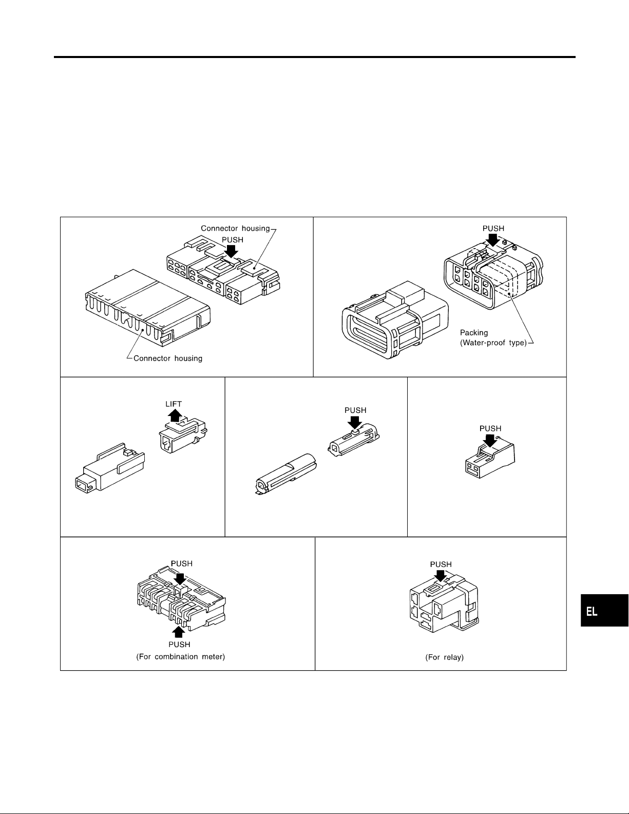
Description
HARNESS CONNECTOR (TAB-LOCKING TYPE)
쐌 The tab-locking type connectors help prevent accidental looseness or disconnection.
쐌 The tab-locking type connectors are disconnected by pushing or lifting the locking tabs.
Refer to illustration below.
Refer to the next page for description of slide-locking type connectors.
CAUTION:
쐌 Do not pull the harness or wires when disconnecting the connector.
쐌 Be careful not to damage the connector support bracket when disconnecting the connector.
[Example]
NDEL0003
NDEL0003S01
GI
MA
EM
LC
EC
FE
AT
AX
SU
BR
ST
RS
BT
HA
SC
IDX
EL-5
SEL769DA
Page 6
Description (Cont’d)
HARNESS CONNECTOR
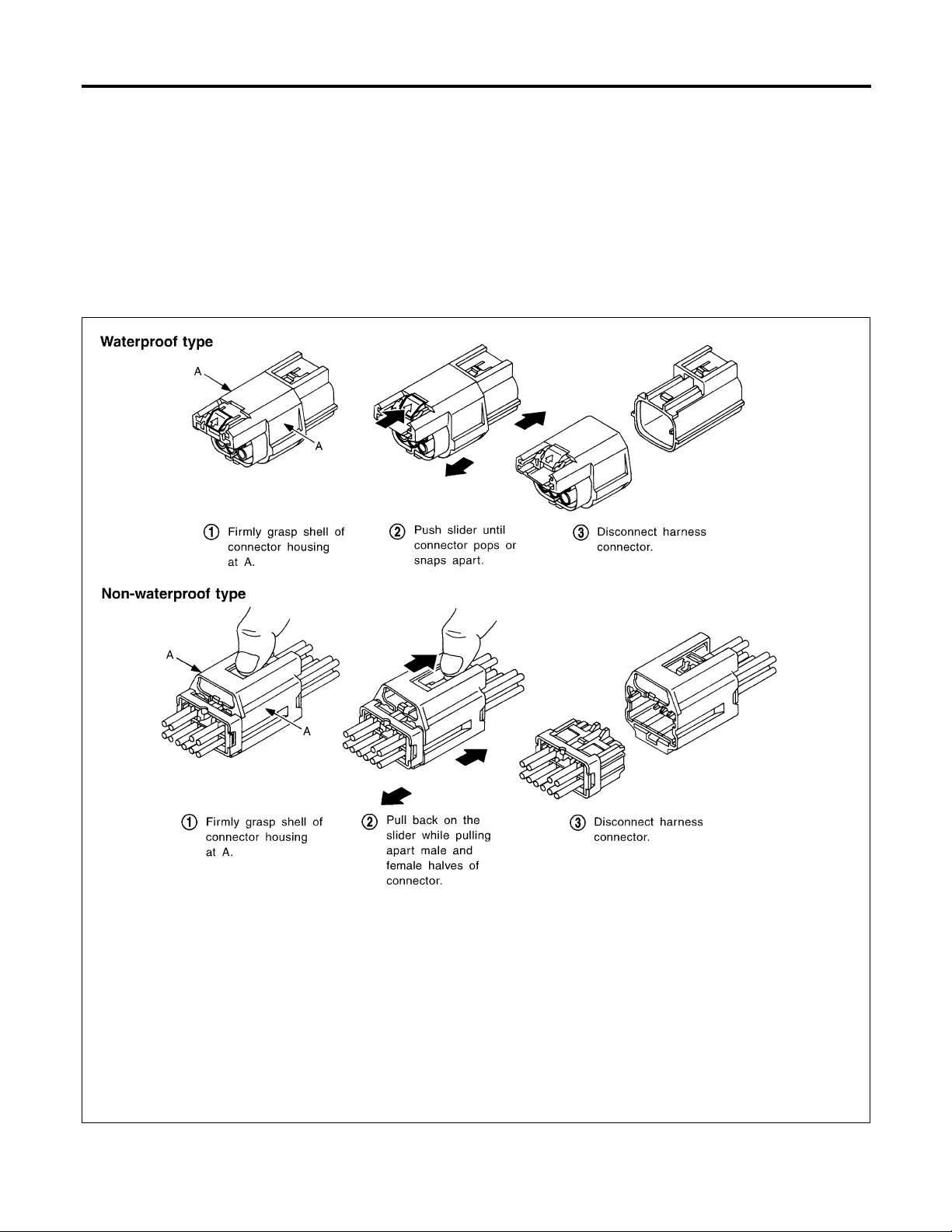
HARNESS CONNECTOR (SLIDE-LOCKING TYPE)
=NDEL0003S02
쐌 A new style slide-locking type connector is used on certain systems and components, especially those
related to OBD.
쐌 The slide-locking type connectors help prevent incomplete locking and accidental looseness or disconnec-
tion.
쐌 The slide-locking type connectors are disconnected by pushing or pulling the slider.
Refer to illustration below.
CAUTION:
쐌 Do not pull the harness or wires when disconnecting the connector.
쐌 Be careful not to damage the connector support bracket when disconnecting the connector.
[Example]
EL-6
AEL299C
Page 7
STANDARDIZED RELAY
Description
Description
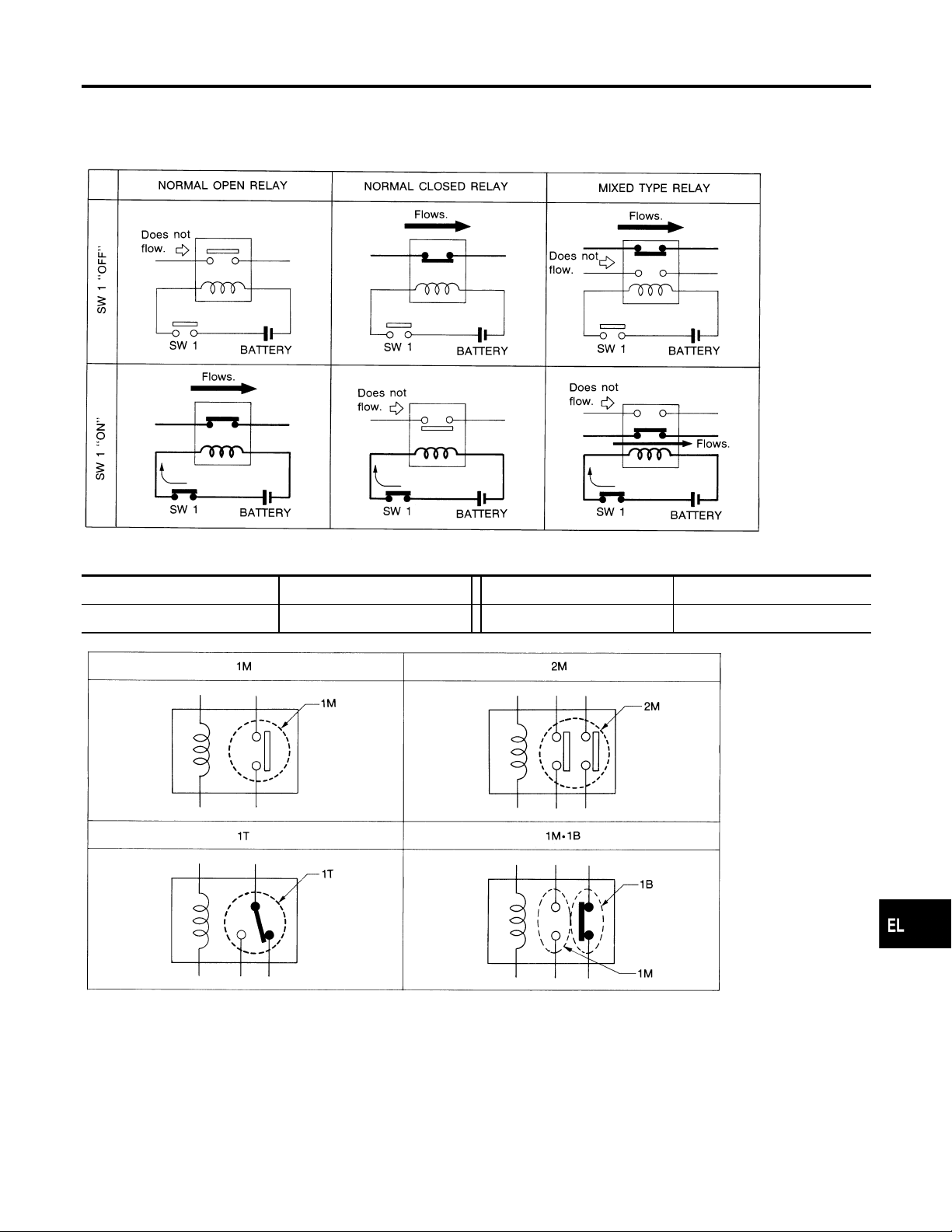
NORMAL OPEN, NORMAL CLOSED AND MIXED TYPE RELAYS
Relays can mainly be divided into three types: normal open, normal closed and mixed type relays.
NDEL0004
NDEL0004S01
SEL881H
GI
MA
EM
LC
EC
FE
AT
AX
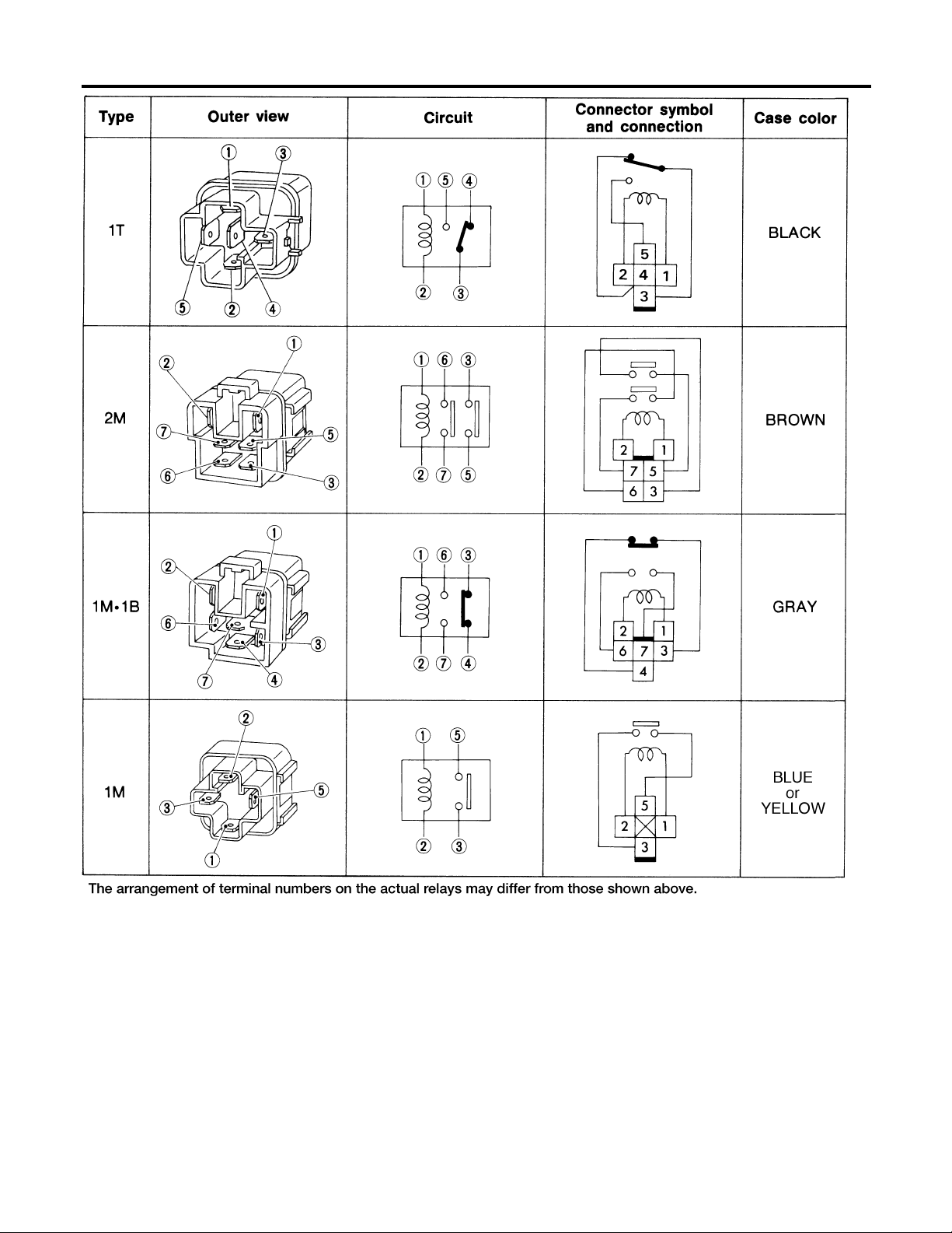
TYPE OF STANDARDIZED RELAYS
1M 1 Make 2M 2 Make
1T 1 Transfer 1M·1B 1 Make 1 Break
NDEL0004S02
SEL882H
SU
BR
ST
RS
BT
HA
SC
IDX
EL-7
Page 8
Description (Cont’d)
STANDARDIZED RELAY
EL-8
AEL174C
Page 9

NOTE:
POWER SUPPLY ROUTING
GI
MA
EM
LC
EC
FE
AT
AX
SU
BR
ST
RS
BT
HA
SC
EL-9
IDX
Page 10

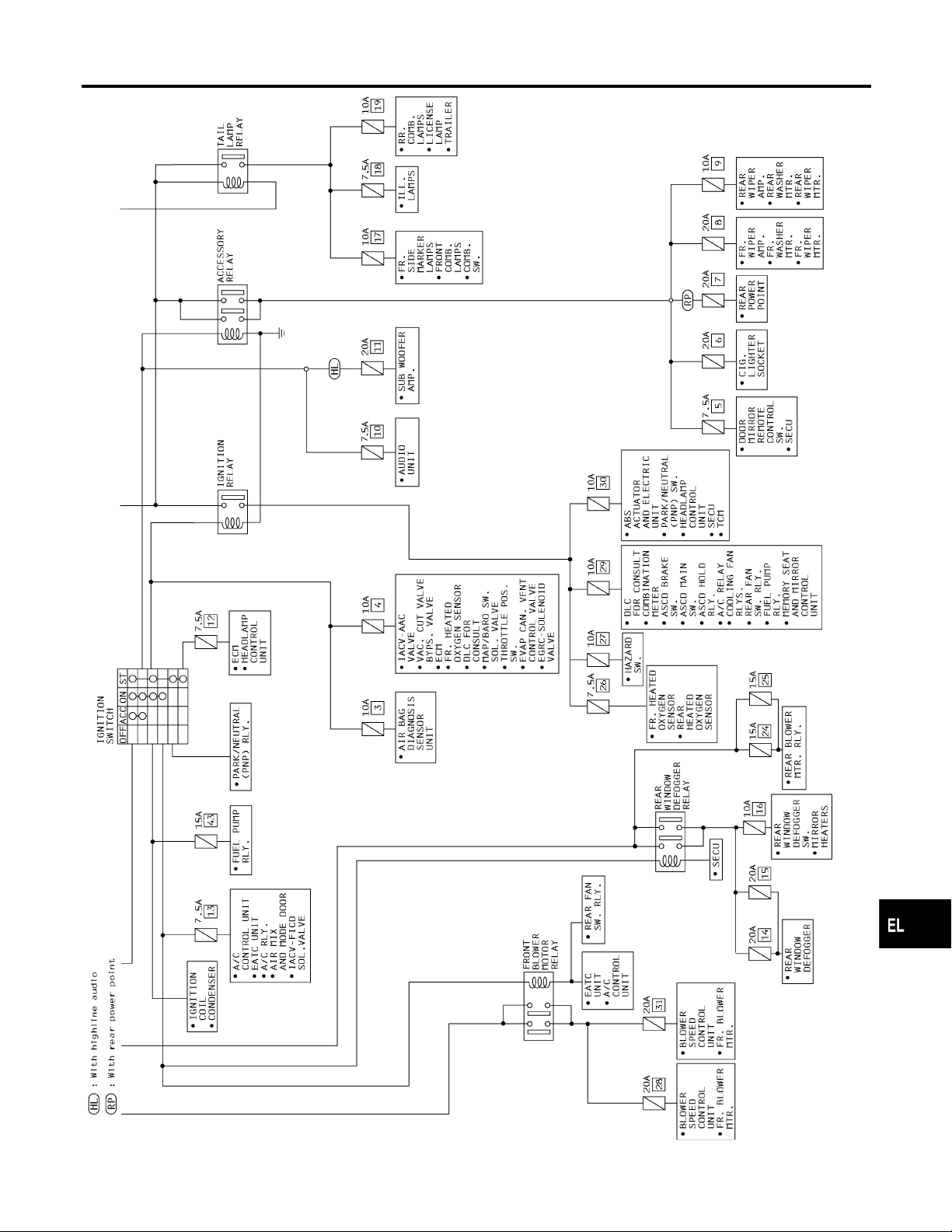
Schematic
POWER SUPPLY ROUTING
Schematic
NDEL0005
EL-10
WEL552A
Page 11
POWER SUPPLY ROUTING
Schematic (Cont’d)
GI
MA
EM
LC
EC
FE
AT
AX
SU
BR
ST
RS
BT
HA
SC
EL-11
IDX
WEL285
Page 12

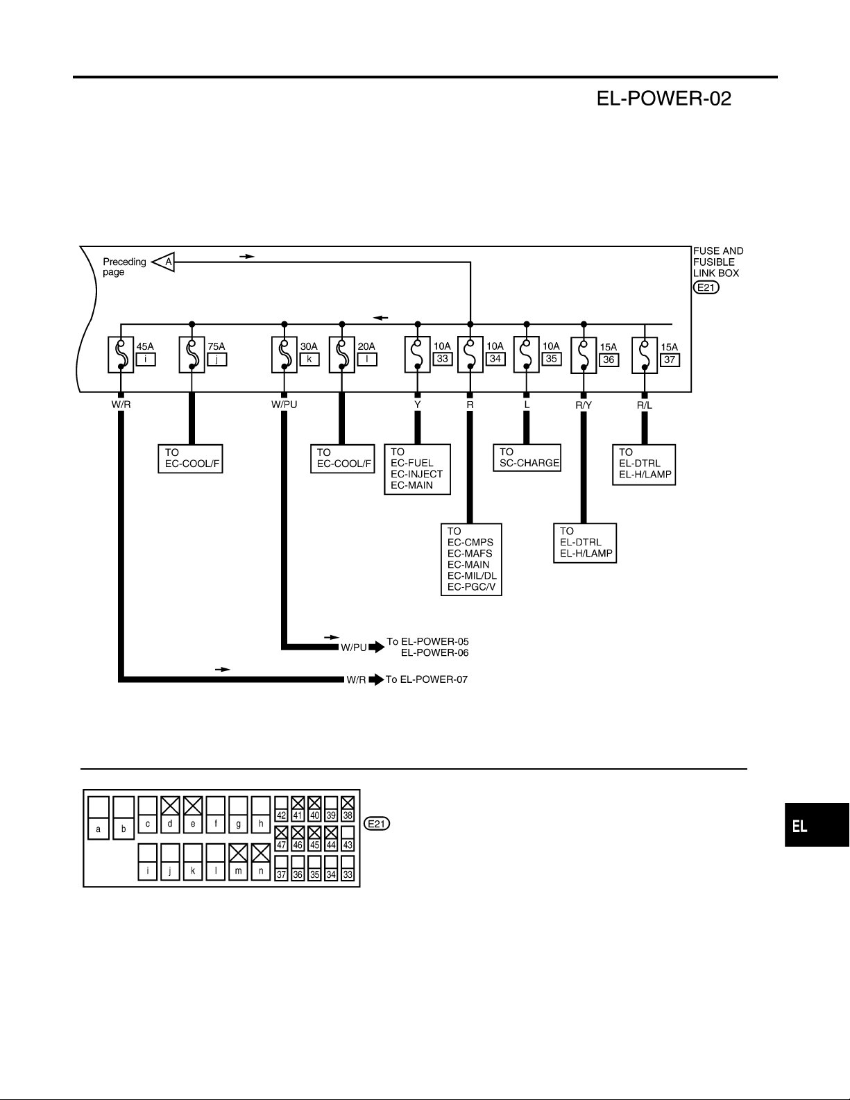
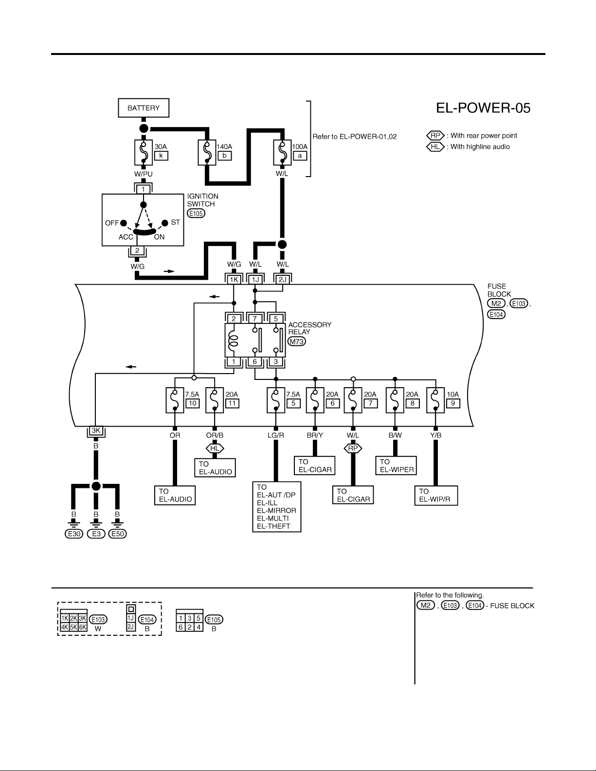
Wiring Diagram — POWER —
POWER SUPPLY ROUTING
Wiring Diagram — POWER —
BATTERY POWER SUPPLY — IGNITION SW. IN ANY POSITION
NOTE:
For detailed ground distribution information, refer to “GROUND DISTRIBUTION”, EL-20.
NDEL0006
NDEL0006S01
EL-12
WEL286
Page 13
POWER SUPPLY ROUTING
Wiring Diagram — POWER — (Cont’d)
GI
MA
EM
LC
EC
FE
AT
AX
SU
BR
ST
RS
BT
HA
SC
EL-13
IDX
WEL553A
Page 14
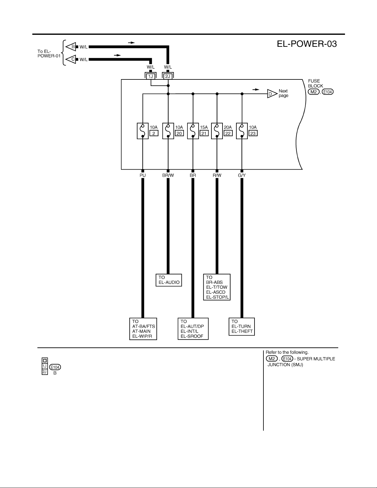
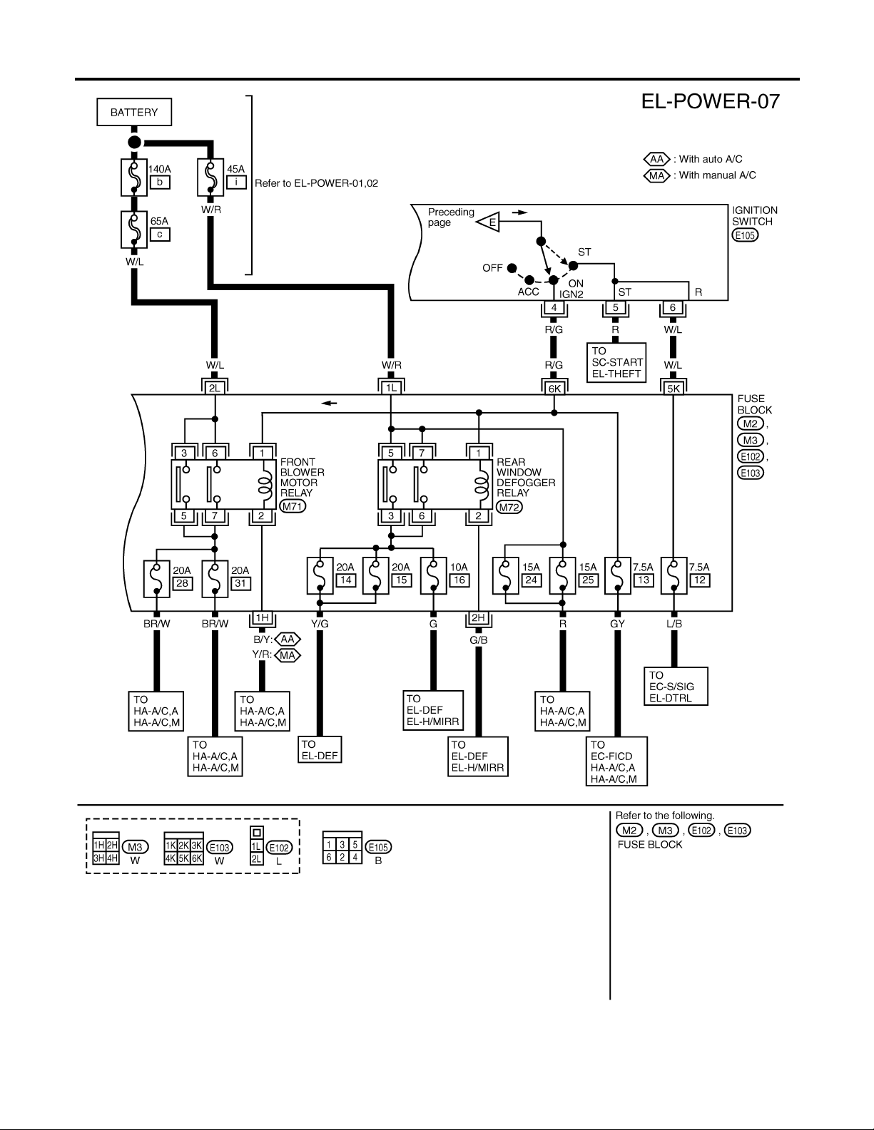
Wiring Diagram — POWER — (Cont’d)
POWER SUPPLY ROUTING
EL-14
WEL288
Page 15
POWER SUPPLY ROUTING
Wiring Diagram — POWER — (Cont’d)
GI
MA
EM
LC
EC
FE
AT
AX
SU
BR
ST
RS
BT
HA
SC
EL-15
IDX
WEL289
Page 16
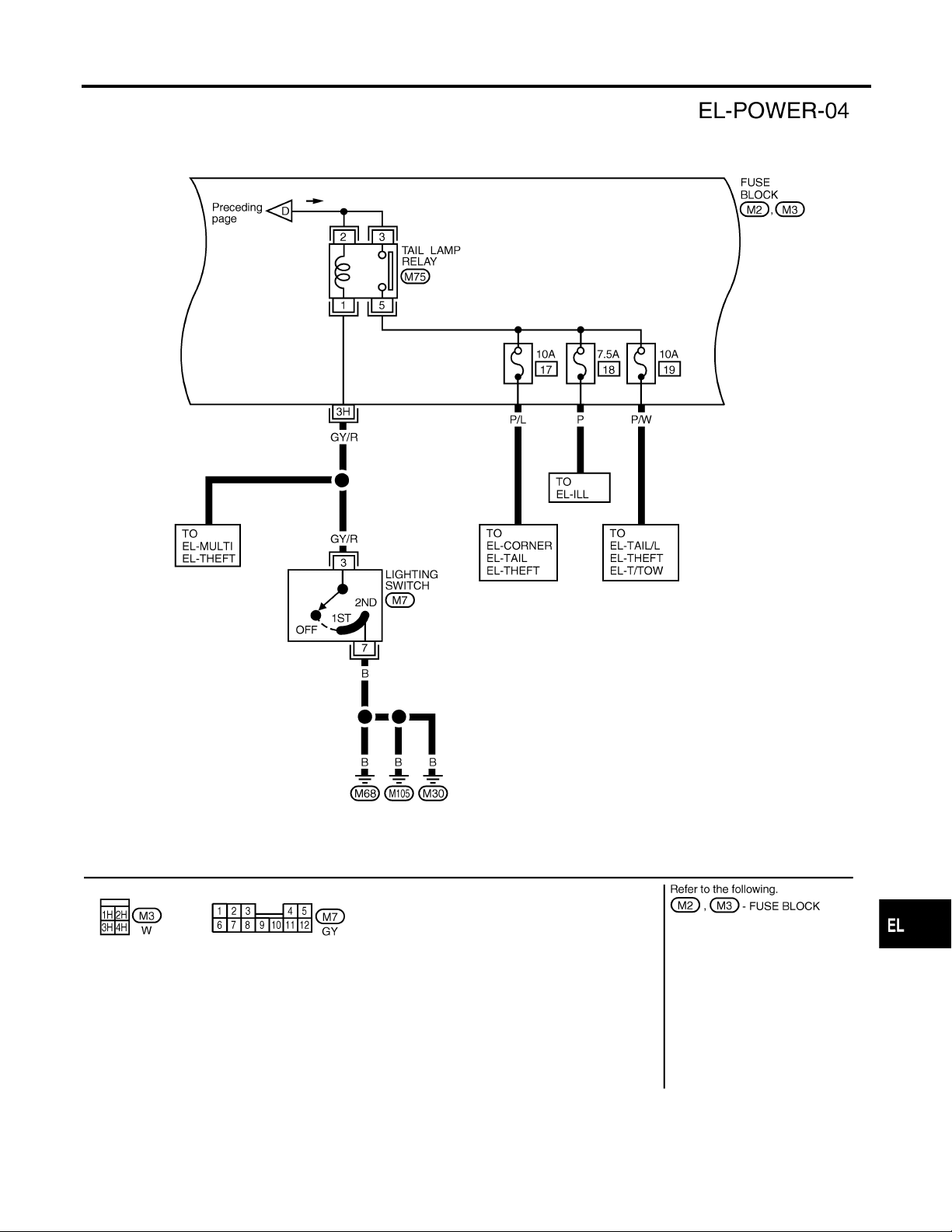
Wiring Diagram — POWER — (Cont’d)
POWER SUPPLY ROUTING
ACCESSORY POWER SUPPLY — IGNITION SW. IN ACC OR ON
NOTE:
For detailed ground distribution information, refer to “GROUND DISTRIBUTION”, EL-20.
=NDEL0006S02
EL-16
WEL290
Page 17

POWER SUPPLY ROUTING
Wiring Diagram — POWER — (Cont’d)
IGNITION POWER SUPPLY — IGNITION SW. IN ON AND/OR START
NOTE:
For detailed ground distribution information, refer to “GROUND DISTRIBUTION”, EL-20.
=NDEL0006S03
GI
MA
EM
LC
EC
FE
AT
AX
SU
BR
ST
RS
BT
HA
SC
IDX
EL-17
WEL291
Page 18
Wiring Diagram — POWER — (Cont’d)
POWER SUPPLY ROUTING
EL-18
WEL292
Page 19
POWER SUPPLY ROUTING
Inspection
CEL083
AEL175C
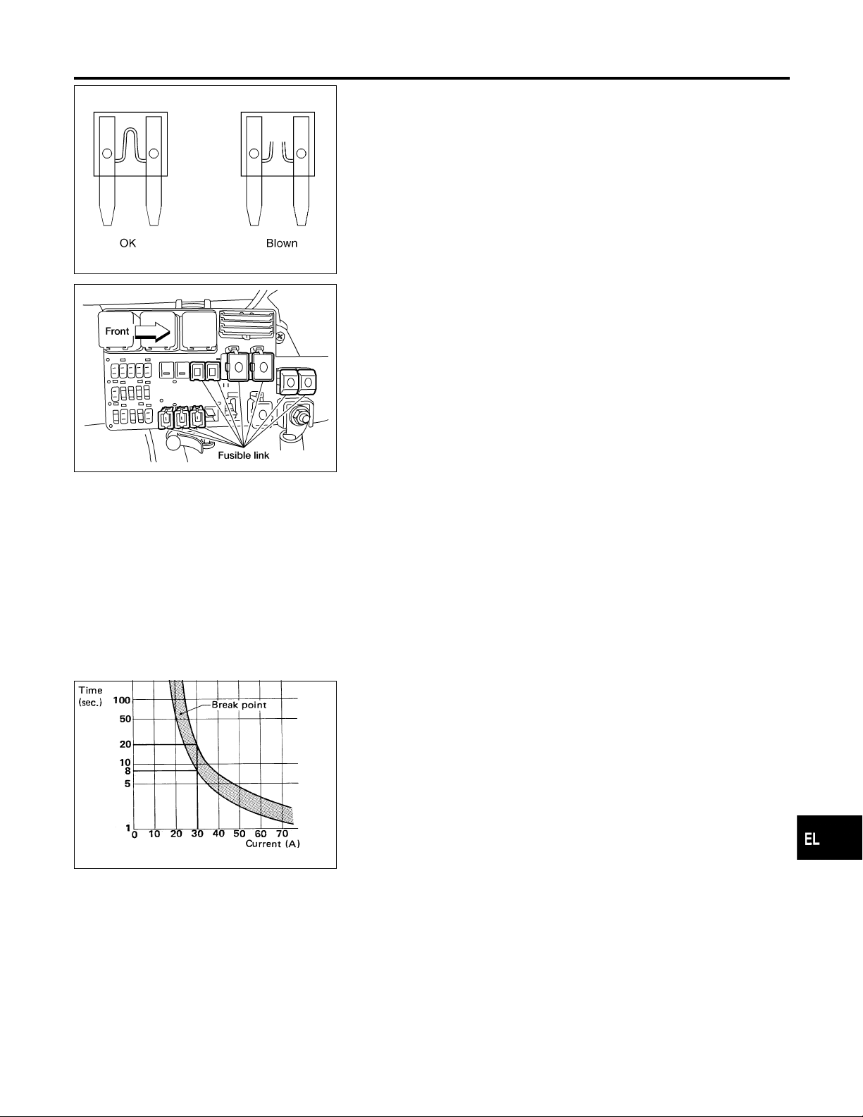
Inspection
FUSE
쐌 If fuse is blown, be sure to eliminate cause of problem
before installing new fuse.
쐌 Use fuse of specified rating. Never use fuse of more than
specified rating.
쐌 Do not partially install fuse; always insert it into fuse
holder properly.
쐌 Remove fuse for “ELECTRICAL PARTS (BAT)” if vehicle is
not used for a long period of time.
FUSIBLE LINK
A melted fusible link can be detected either by visual inspection or
by feeling with finger tip. If its condition is questionable, use circuit
tester or test lamp.
CAUTION:
쐌 If fusible link should melt, it is possible that critical circuit
(power supply or large current carrying circuit) is shorted.
In such a case, carefully check and eliminate cause of
problem.
쐌 Never wrap outside of fusible link with vinyl tape. Impor-
tant: Never let fusible link touch any other wiring harness,
vinyl or rubber parts.
NDEL0007
NDEL0007S01
NDEL0007S02
GI
MA
EM
LC
EC
FE
AT
AX
SBF284E
CIRCUIT BREAKER
For example, when current is 30A, the circuit is broken within 8 to
20 seconds.
NDEL0007S03
SU
BR
ST
RS
BT
HA
SC
IDX
EL-19
Page 20
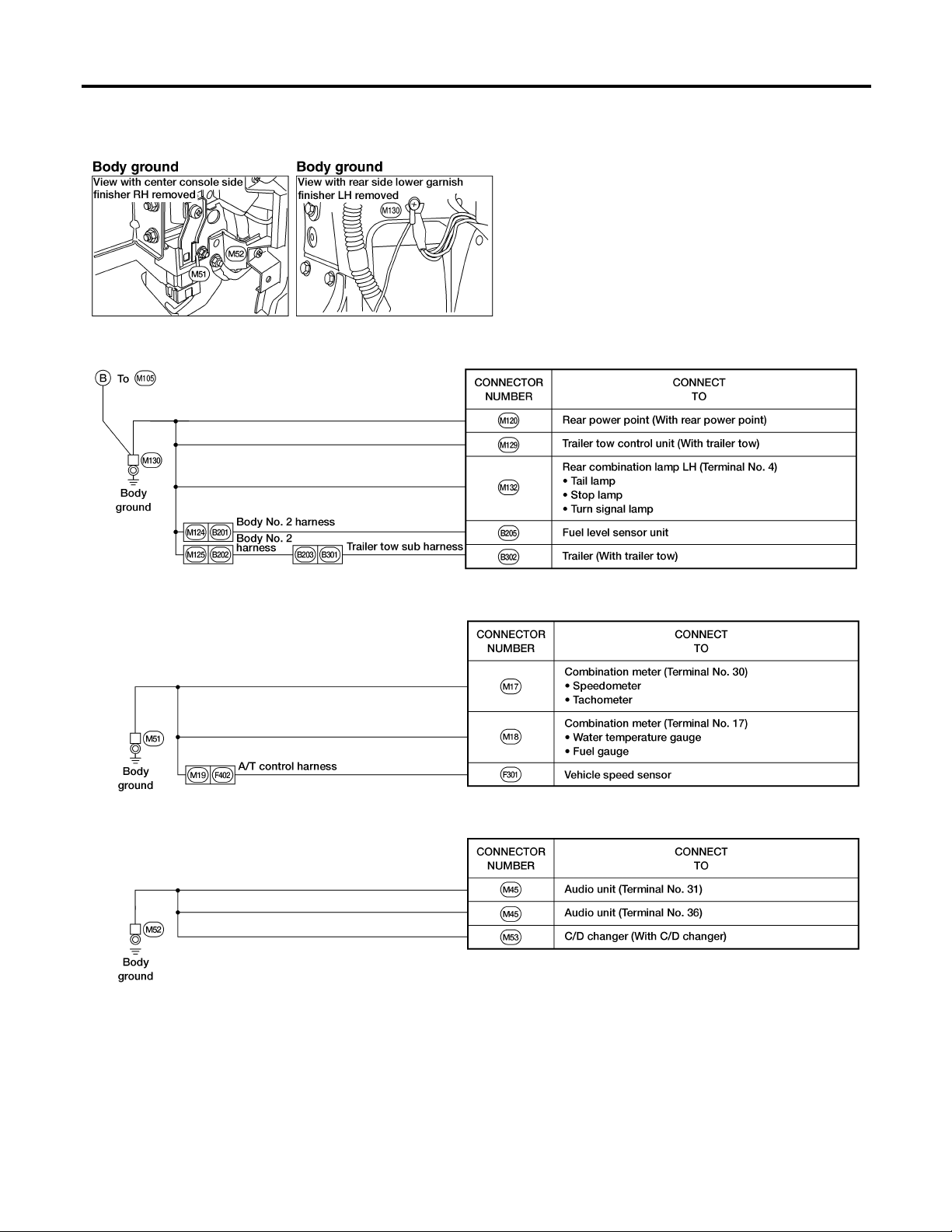
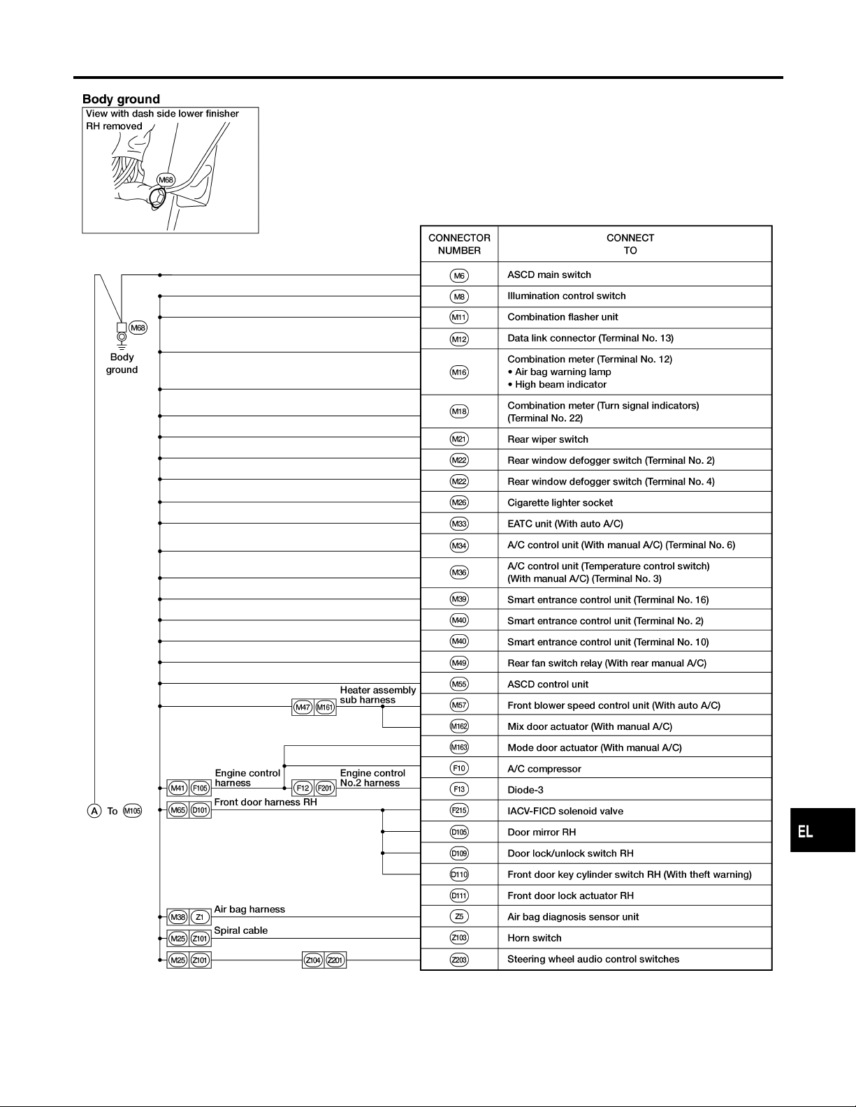
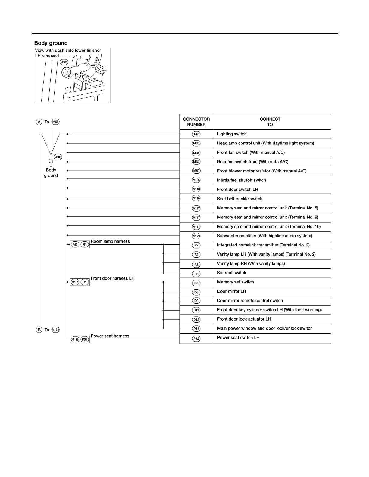
Ground Distribution
GROUND
Ground Distribution
MAIN HARNESS
NDEL0008
NDEL0008S01
EL-20
WEL294
Page 21
GROUND
Ground Distribution (Cont’d)
GI
MA
EM
LC
EC
FE
AT
AX
SU
BR
ST
RS
BT
HA
SC
EL-21
IDX
WEL295
Page 22
Ground Distribution (Cont’d)
GROUND
EL-22
WEL296
Page 23
GROUND
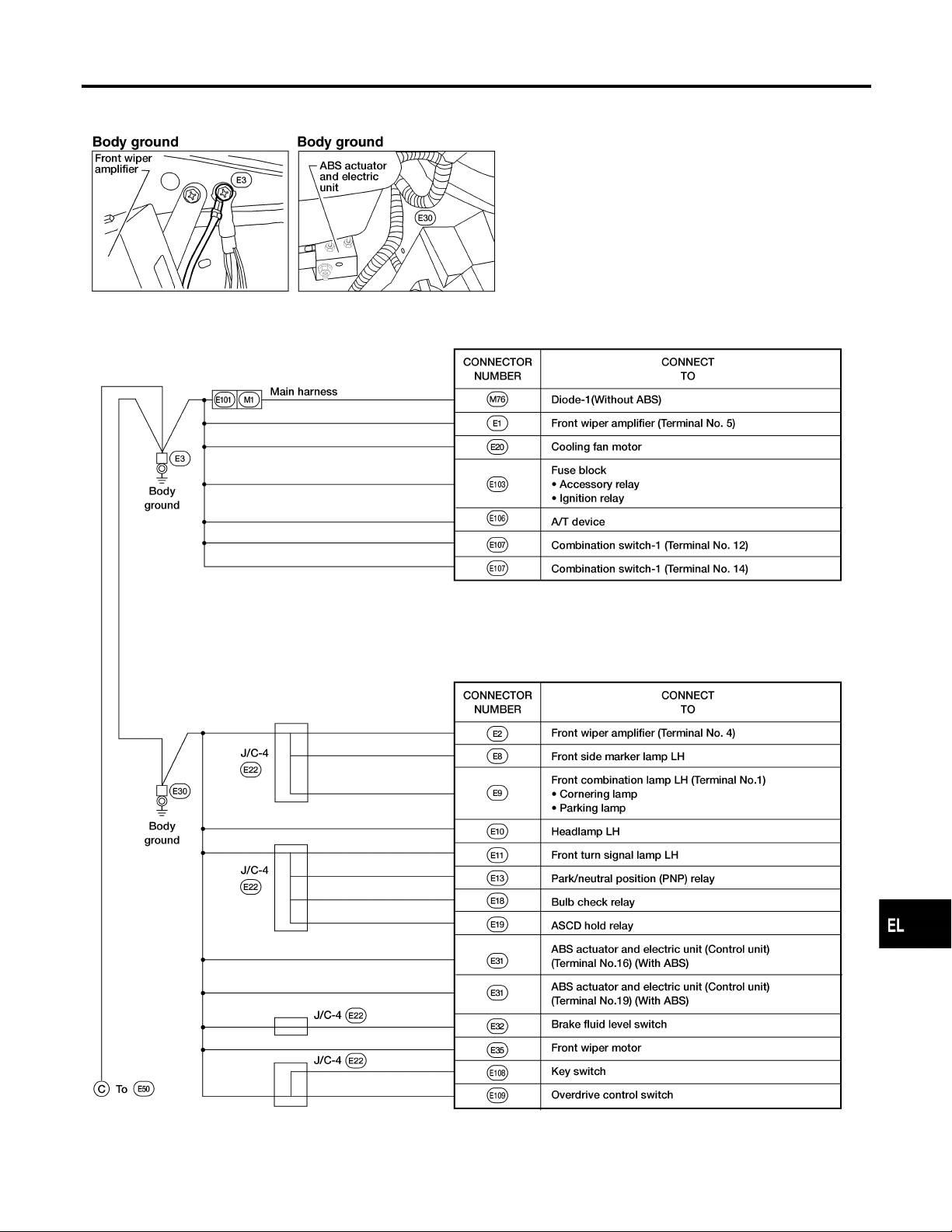
Ground Distribution (Cont’d)
ENGINE ROOM HARNESS
NDEL0008S02
GI
MA
EM
LC
EC
FE
AT
AX
SU
BR
ST
RS
BT
HA
SC
IDX
EL-23
WEL297
Page 24

Ground Distribution (Cont’d)
GROUND
GENERATOR HARNESS
NDEL0008S03
EL-24
WEL298
Page 25
GROUND
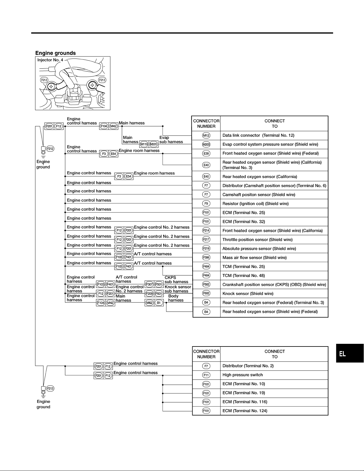
Ground Distribution (Cont’d)
ENGINE CONTROL SUB HARNESS
NDEL0008S04
GI
MA
EM
LC
EC
FE
AT
AX
SU
BR
ST
RS
BT
HA
SC
IDX
EL-25
WEL299
Page 26
Ground Distribution (Cont’d)
GROUND
BODY NO. 2 HARNESS
NDEL0008S05
EL-26
WEL300
Page 27
GROUND
Ground Distribution (Cont’d)
BACK DOOR NO. 2 HARNESS
NDEL0008S06
GI
MA
EM
LC
EC
FE
AT
AX
SU
BR
ST
RS
BT
HA
SC
IDX
EL-27
WEL301
Page 28
Ground Distribution (Cont’d)
GROUND
REAR DEFOGGER GROUND HARNESS
NDEL0008S07
EL-28
WEL302
Page 29
COMBINATION SWITCH
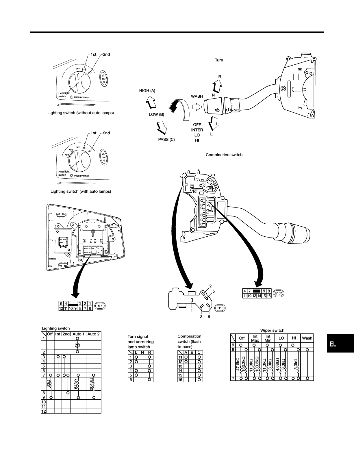
Check
Check
NDEL0009
GI
MA
EM
LC
EC
FE
AT
AX
SU
BR
ST
RS
BT
HA
SC
IDX
EL-29
AEL862B
Page 30
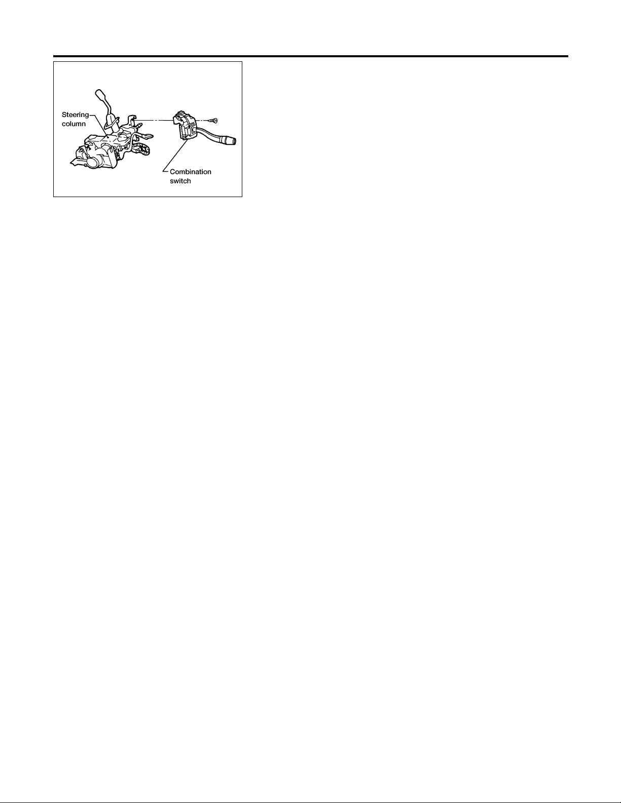
Replacement
COMBINATION SWITCH
AEL112A
Replacement
NDEL0010
쐌 To remove combination switch base, remove base attaching
screws.
EL-30
Page 31

STEERING SWITCH
Check
Check
NDEL0011
GI
MA
EM
LC
EC
FE
AT
AX
SU
BR
ST
RS
BT
HA
SC
IDX
EL-31
AEL863B
Page 32

HEADLAMP (FOR USA)
Component Parts and Harness Connector Location
Component Parts and Harness Connector
Location
NDEL0012
WEL280
System Description
NDEL0013
The headlamps are controlled by the headlamp control unit.
Power is supplied at all times
쐌 through 15A fuse (No. 37, located in the fuse and fusible link box)
쐌 to headlamp control unit terminal 7 (for LH headlamp)
쐌 through 15A fuse (No. 36, located in the fuse and fusible link box)
쐌 to headlamp control unit terminal 5 ( for RH headlamp).
MANUAL OPERATION
Low Beam Operation
NDEL0013S01
NDEL0013S0101
When the combination switch is placed in the LOW BEAM (B) position, with lighting switch in the headlamp
ON (2ND) position, ground is supplied
쐌 to headlamp control unit terminal 9
쐌 through lighting switch terminal 8
쐌 to lighting switch terminal 7
쐌 through body grounds M68, M105 and M130.
Then, power is supplied
쐌 from headlamp control unit terminal 3
쐌 to LH headlamp terminal 3
쐌 from headlamp control unit terminal 6
쐌 to RH headlamp terminal 3.
Ground is supplied to each headlamp terminal 2 through body grounds E3, E30 and E50.
With power and ground supplied, the low beam headlamps will illuminate.
High Beam Operation
NDEL0013S0102
When the lighting switch is placed in the headlamp ON (2ND) position, ground is supplied to headlamp control unit terminal 9 in the same manner as low beam operation.
With combination switch in the HIGH BEAM (A) position, ground is supplied
쐌 to headlamp control unit terminal 18
쐌 through combination switch terminal 11
쐌 to combination switch terminal 14
쐌 through body grounds E3, E30 and E50.
Then, power is supplied
EL-32
Page 33

HEADLAMP (FOR USA)
System Description (Cont’d)
쐌 from headlamp control unit terminal 8
쐌 to LH headlamp terminal 1
쐌 from headlamp control unit terminal 4
쐌 to RH headlamp terminal 1.
Ground is supplied to each headlamp terminal 2 through body grounds E3, E30 and E50.
With power and ground supplied, the high beam headlamps will illuminate.
Power is also supplied
쐌 from headlamp control unit terminal 8 (models without autolamp), 13 (models with autolamp)
쐌 to combination meter terminal 6 for HIGH BEAM indicator.
Ground is supplied to combination meter terminal 12 through body grounds M68, M105 and M130.
With power and ground supplied the HIGH BEAM indicator will illuminate.
GI
MA
EM
LC
Flash to Pass Operation
When the combination switch is placed in the FLASH TO PASS (C) position, ground is supplied
쐌 to headlamp control unit terminal 20
쐌 through combination switch terminal 13
쐌 to combination switch terminal 12
쐌 through body grounds E3, E30 and E50.
Then, power is supplied to each headlamp (HIGH) from headlamp control unit to turn on the lamps in the same
manner as high beam operation.
AUTO LAMP OPERATION (IF EQUIPPED)
Automatic Illumination
When the ignition switch is in ON position, power is supplied
쐌 through 10A fuse (No. 30, located in the fuse block)
쐌 to headlamp control unit terminal 2.
With power at terminal 2 and lighting switch in AUTO1 or AUTO2 position, the headlamp control unit will measure the ambient light intensity through terminals 10 and 21. If the autolamp sensor does not detect sufficient
light, power is supplied to headlamps in the same manner as low or high beam operation. Headlamp control
unit decides to illuminate headlamps (Low or High) according to combination switch position (LOW or HIGH).
At this time, ground is also supplied to tail lamp relay through headlamp control unit terminal 12 to energize
tail lamp relay. Then tail lamp relay supplies power to turn on parking, license, tail lamps and illumination. For
detailed wiring diagrams, refer to “PARKING, LICENSE, TAIL LAMPS”, EL-53 and “ILLUMINATION”, EL-68.
Shut-off Delay
While the headlamps are lit in the automatic illumination mode, the ignition switch is turned from ON to OFF
position and auto lamp shut-off delay timer starts. At this time, ground to tail lamp relay is discontinued.
The delay time is set based on the resistance value at headlamp control unit terminal 14. With the timer
running, the headlamps remain lit. When the timer reaches the end of its cycle, the headlamps turn off.
Headlamp lighting time can be adjusted from 0 to 3 minutes.
NDEL0013S0103
NDEL0013S02
NDEL0013S0201
NDEL0013S0202
EC
FE
AT
AX
SU
BR
ST
RS
BT
HA
THEFT WARNING SYSTEM
If the theft warning system is triggered, alarm signal is sent
쐌 to headlamp control unit terminal 19
쐌 from smart entrance control unit terminal 2.
Then headlamp control unit operates to flash the high beams. For details, refer to “THEFT WARNING
SYSTEM”, EL-253.
NDEL0013S03
EL-33
SC
IDX
Page 34

Wiring Diagram — H/LAMP —
HEADLAMP (FOR USA)
Wiring Diagram — H/LAMP —
NDEL0014
EL-34
WEL190
Page 35

HEADLAMP (FOR USA)
Wiring Diagram — H/LAMP — (Cont’d)
GI
MA
EM
LC
EC
FE
AT
AX
SU
BR
ST
RS
BT
HA
SC
EL-35
IDX
WEL191
Page 36

Trouble Diagnoses
HEADLAMP (FOR USA)
Symptom Possible cause Repair order
LH headlamps do not illuminate
with any operation.
(RH headlamps operate properly.)
RH headlamps do not illuminate with any operation.
(LH headlamps operate properly.)
Both LH and RH headlamps do
not illuminate with lighting
switch operation.
(Headlamps illuminate with
auto lamp operation.)
LH high beam does not illuminate with any operation.
Trouble Diagnoses
SYMPTOM AND INSPECTION CHART
1. Bulb
2. 15 A fuse
3. Grounds E3, E30 and E50
1. Bulb
2. 15 A fuse
3. Grounds E3, E30 and E50
1. Lighting switch
2. Lighting switch ground circuit
3. Headlamp on signal
1. Bulb
2. LH high beam on signal
3. Harness for open or short
NDEL0015
NDEL0015S01
1. Check bulb.
2. Check 15 A fuse (No. 37, located in fuse and fusible
link box). Verify battery voltage is present at terminal 7
of headlamp control unit.
3. Check grounds E3, E30 and E 50.
1. Check bulb.
2. Check 15 A fuse (No. 36, located in fuse and fusible
link box). Verify battery voltage is present at terminal 5
of headlamp control unit.
3. Check grounds E3, E30 and E50.
1. Check lighting switch.
2. Check continuity between lighting switch terminal 7 and
ground.
3. Check harness for open or short between lighting
switch terminal 8 and headlamp control unit terminal 9.
1. Check bulb.
2. Verify battery voltage is present at terminal 8 of headlamp control unit with lighting switch in the headlamp
ON (2ND) position and combination switch in HIGH
BEAM (A) position.
3. Check harness for open or short between headlamp
control unit terminal 8 and LH headlamp terminal 1.
LH low beam does not illuminate with any operation.
RH high beam does not illuminate with any operation.
RH low beam does not illuminate with any operation.
High beam indicator does not
illuminate.
1. Bulb
2. LH low beam on signal
3. Harness for open or short
1. Bulb
2. RH high beam on signal
3. Harness for open or short
1. Bulb
2. RH low beam on signal
3. Harness for open or short
1. Bulb
2. High beam indicator on signal
3. Harness for open or short
4. Combination meter ground circuit
1. Check bulb.
2. Verify battery voltage is present at terminal 3 of headlamp control unit with lighting switch in the headlamp
ON (2ND) position and combination switch in LOW
BEAM (B) position.
3. Check harness for open or short between headlamp
control unit terminal 3 and LH headlamp terminal 3.
1. Check bulb.
2. Verify battery voltage is present at terminal 4 of headlamp control unit with lighting switch in the headlamp
ON (2ND) position and combination switch in HIGH
BEAM (A) position.
3. Check harness for open or short between headlamp
control unit terminal 4 and RH headlamp terminal 1.
1. Check bulb.
2. Verify battery voltage is present at terminal 6 of headlamp control unit with lighting switch in the headlamp
ON (2ND) position and combination switch in LOW
BEAM (B) position.
3. Check harness for open or short between headlamp
control unit terminal 6 and RH headlamp terminal 3.
1. Check bulb.
2. Verify battery voltage is present at terminal 13 (with
autolamp) or 8 (without autolamp) of headlamp control
unit with lighting switch in headlamp ON (2ND) position
and combination switch in HIGH BEAM (A) position.
3. Check harness for open or short between headlamp
control unit terminal 13 and combination meter terminal
6.
4. Check continuity between combination meter terminal
12 and ground.
EL-36
Page 37

HEADLAMP (FOR USA)
Trouble Diagnoses (Cont’d)
Symptom Possible cause Repair order
Headlamp beams cannot
switch between low/high.
Flash to pass cannot be operated.
(High beams illuminate with
other operation.)
Automatic illumination does not
operate properly.
Shut off delay does not operate
properly.
Tail lamps do not operate by
automatic illumination.
(Headlamps operate properly
by automatic illumination.)
1. Combination switch-1
2. Combination switch-1 ground circuit
3. Harness for open or short
1. Combination switch-1
2. Combination switch-1 ground circuit
3. Harness for open or short
—
—
—
AUTOLAMP CHECK
1 CHECK HEADLAMP OPERATION
Do headlamps operate properly with lighting switch?
YesorNo
Yes 䊳 GO TO 2.
No 䊳 Check headlamp, refer to EL-36.
1. Check combination switch-1.
2. Check continuity between combination switch terminal
14 and ground.
3. Check harness for open or short between headlamp
control unit terminal 18 and combination switch-1 terminal 11.
1. Check combination switch-1.
2. Check continuity between combination switch terminal
12 and ground.
3. Check harness for open or short between headlamp
control unit terminal 20 and combination switch-1 terminal 13.
Go to “AUTOLAMP CHECK”, EL-37.
Go to “SHUT OFF DELAY SWITCH CHECK”, EL-40.
Go to “TAIL LAMP RELAY CHECK”, EL-40.
NDEL0015S02
GI
MA
EM
LC
EC
FE
AT
AX
SU
BR
ST
2 CHECK AUTOLAMP OPERATION
1. Turn ignition switch to ON position.
2. Turn lighting switch to AUTO1 or AUTO2 position.
3. Obstruct autolamp sensor.
Do headlamps and tail lamps illuminate?
Yes 䊳 Go to “SHUT OFF DELAY SWITCH CHECK”, EL-40.
No 䊳 GO TO 3.
RS
BT
HA
SC
IDX
EL-37
Page 38

HEADLAMP (FOR USA)
Trouble Diagnoses (Cont’d)
3 CHECK IGNITION SWITCH ON SIGNAL
Check voltage between headlamp control unit terminal 2 and ground with ignition switch ON.
Does battery voltage exist?
Yes 䊳 GO TO 4.
No 䊳 Check the following.
쐌 10 A fuse (No. 30, located in the fuse block)
쐌 Harness for open or short between fuse and headlamp control unit
4 CHECK CONTROL UNIT GROUND
Check continuity between lighting control unit terminal 22 and ground.
AEL935B
Does continuity exist?
Yes 䊳 GO TO 5.
No 䊳 Repair harness or connectors.
AEL171C
EL-38
Page 39

HEADLAMP (FOR USA)
Trouble Diagnoses (Cont’d)
5 CHECK AUTOLAMP SENSOR
1. Disconnect autolamp sensor connector.
2. Check continuity between autolamp sensor connector terminals 2 and 1. With positive lead on pin 1 and negative lead
on pin 2.
Continuity should exist.
3. Reverse leads.
Continuity should not exist.
NOTE:
Specifications may vary depending on tester type. Before performing this inspection, refer to instruction manual for your
tester.
GI
MA
EM
LC
EC
FE
AT
AEL936B
OK or NG
OK 䊳 Check harness for open or short between headlamp control unit and autolamp sensor.
NG 䊳 Replace autolamp sensor.
AX
SU
BR
ST
RS
BT
HA
SC
EL-39
IDX
Page 40

Trouble Diagnoses (Cont’d)
HEADLAMP (FOR USA)
SHUT OFF DELAY SWITCH CHECK
1 CHECK SHUT-OFF DELAY FUNCTION
1. Disconnect lighting switch.
2. Check resistance between lighting switch terminals 7 and 9.
OK or NG
OK 䊳 Shut-off delay switch is OK. GO TO 2.
NG 䊳 Replace the switch.
=NDEL0015S03
AEL937B
AEL955B
2 CHECK IGNITION SWITCH ON SIGNAL CIRCUIT
1. Disconnect headlamp control unit.
2. Check voltage between headlamp control unit terminal 2 and ground with ignition switch OFF.
Does battery voltage exist?
Yes 䊳 Repair the harness between fuse and headlamp control unit.
No 䊳 Replace headlamp control unit.
TAIL LAMP RELAY CHECK
1 CHECK TAIL LAMP OPERATION
Do tail lamps illuminate with lighting switch operation?
NOTE:
For wiring diagram of tail lamp relay, refer to “PARKING, LICENSE AND TAIL LAMPS”, EL-53
YesorNo
Yes 䊳 GO TO 4.
No 䊳 GO TO 2.
AEL324C
NDEL0015S04
EL-40
Page 41

HEADLAMP (FOR USA)
2 CHECK TAIL LAMP RELAY
1. Apply 12 V direct current between relay terminal 1 and 2.
2. Check continuity between relay terminals 3 and 5.
Trouble Diagnoses (Cont’d)
GI
MA
EM
LC
12 V applied:
Continuity exists.
No voltage applied
Continuity should not exist.
OK or NG
OK 䊳 GO TO 3.
NG 䊳 Replace the relay.
3 CHECK POWER SUPPLY FOR TAIL LAMP RELAY
Check voltage between tail lamp relay terminals 2, 3 and ground.
Does battery voltage exist?
Yes 䊳 Check tail lamp relay connector and tail lamp circuits.
No 䊳 Check harness between tail lamp relay and battery.
AEL938B
AEL939B
EC
FE
AT
AX
SU
BR
ST
RS
BT
HA
EL-41
SC
IDX
Page 42

HEADLAMP (FOR USA)
Trouble Diagnoses (Cont’d)
4 CHECK HEADLAMP CONTROL UNIT TAIL LAMP CONTROL CIRCUIT-1
1. Turn ignition switch to ON position.
2. Turn lighting switch to AUTO1 or AUTO2 position.
3. Obstruct autolamp sensor.
4. Check voltage between headlamp control unit terminal 12 and ground.
Does battery voltage exist?
Yes 䊳 Replace headlamp control unit.
No 䊳 GO TO 5.
5 CHECK HEADLAMP CONTROL UNIT TAIL LAMP CONTROL CIRCUIT-2
1. Turn ignition switch to OFF position.
2. Check voltage between headlamp control unit terminal 12 and ground.
AEL172C
Does battery voltage exist?
Yes 䊳 Autolamp control system is OK.
No 䊳 Check harness between headlamp control unit and tail lamp relay.
HEADLAMP CONTROL UNIT INSPECTION TABLE
Terminal
No.
2* LG
3OR
4 OR/W
5 R/Y
Wire
color
Ignition switch on signal Ignition switch OFF,ACC position 0
LH headlamp low beam Lighting switch in the headlamp ON (2ND) position
RH headlamp high beam Lighting switch in the ON (2ND) position and combi-
Power source for RH headlamp
Item Condition
Ignition switch ON, START position 12
and combination switch in LOW BEAM (B) position
All other conditions 0
nation switch in HIGH BEAM (A) position
All other conditions 0
— 12
AEL323C
NDEL0015S05
Voltage
(Approximate
value)
12
12
EL-42
Page 43

HEADLAMP (FOR USA)
Trouble Diagnoses (Cont’d)
Terminal
No.
6 R/W
7 R/L
8 OR/L
9Y
10* G
12* GY/R
13* OR/L
Wire
color
Voltage
Item Condition
RH headlamp low beam Lighting switch in the headlamp ON (2ND) position
and combination switch in LOW BEAM (B) position
All other conditions 0
Power source for LH headlamp
LH headlamp high beam Lighting switch in the ON (2ND) position and combi-
nation switch in HIGH BEAM (A) position
All other conditions 0
Lighting switch OFF, 1ST position 12
Headlamp ON (2ND) position 0
Autolamp sensor(+) Sensor struck by light —
Sensor obstructed —
Tail lamp relay Autolamp is not operating and lighting switch is in the
OFF position
Autolamp is operating 0
High beam indicator Lighting switch in the ON (2ND) position and combi-
nation switch in HIGH BEAM (A) position
Combination switch in FLASH TO PASS (C) position
— 12
(Approximate
value)
12
12
12
12
GI
MA
EM
LC
EC
FE
AT
AX
SU
All other conditions 0
BR
14* L/W
18 LG/R
19 P/W
Shut-off delay switch (lighting
switch)
Combination switch HIGH BEAM (A) or FLASH TO PASS (C) position 0
Smart entrance control unit
(with theft warning)
OFF 0.5
AUTO1 3.5
AUTO2 4.5
All other conditions 12
When theft warning system is in alarm phase or panic
operation is activated by multi-remote control system
All other conditions 12
0
ST
RS
BT
HA
20 BR
21* B/W Autolamp sensor(-) ——
22* B Ground ——
*: Marked terminals are available only for models with autolamps.
Combination switch FLASH TO PASS (C) position 0
All other conditions 12
SC
IDX
EL-43
AEL940B
Page 44

Bulb Replacement
HEADLAMP (FOR USA)
AEL176C
Bulb Replacement
NDEL0016
The headlamp is a semi-sealed beam type which uses a replaceable halogen bulb. The bulb can be replaced from the engine compartment side without removing the headlamp body.
쐌 Grasp only the plastic base when handling the bulb. Never
touch the glass envelope.
1. Disconnect the battery cable.
2. Disconnect the harness connector from the back side of the
bulb.
3. Turnthe bulb retaining ring counterclockwise until it is free from
the headlamp reflector, and then remove it.
4. Remove the headlamp bulb carefully. Do not shake or rotate
the bulb when removing it.
5. Install in the reverse order of removal.
CAUTION:
Do not leave headlamp reflector without bulb for a long period
of time. Dust, moisture, smoke, etc. entering headlamp body
may affect the performance of the headlamp. Remove headlamp bulb from the headlamp reflector just before a replacement bulb is installed.
Aiming Adjustment
NDEL0017
When performing headlamp aiming adjustment, use an aiming
machine, aiming wall screen or headlamp tester.Aimers should be
in good repair, calibrated and operated in accordance with respective operation manuals.
If any aimer is not available, aiming adjustment can be done as
follows:
For details, refer to the regulations in your own country.
1) Keep all tires inflated to correct pressures.
2) Place vehicle and tester on one and same flat surface.
3) Seethat there is no-load in vehicle (coolant, engine oil filled up
to correct level and full fuel tank) other than the driver (or
equivalent weight placed in driver’s position).
AEL177C
AIMER ADJUSTMENT MARK
NDEL0017S01
When using a mechanical aimer, adjust adapter legs to the data
marked on the headlamps.
Example
20V23H
Horizontal side: 23
Vertical side: 20
EL-44
Page 45

HEADLAMP (FOR USA)
Aiming Adjustment (Cont’d)
AEL178C
LOW BEAM
1. Turn headlamp low beam on.
2. Use adjusting screws to perform aiming adjustment.
쐌 Upper edge and left edge of high intensity zone should be
within the range shown at left. Adjust headlamps accordingly.
쐌 Dotted lines in illustration show center of headlamp.
“H”: Horizontal center line of headlamps
“W
”: Distance between each headlamp center
L
NDEL0017S02
GI
MA
EM
LC
EC
FE
AT
AX
SEL866L
SU
BR
ST
RS
BT
HA
SC
IDX
EL-45
Page 46

HEADLAMP (FOR CANADA) — DAYTIME LIGHT SYSTEM —
Component Parts and Harness Connector Location
Component Parts and Harness Connector
Location
NDEL0018
WEL280
System Description
NDEL0020
The headlamps are controlled by the headlamp control unit.
Power is supplied at all times
쐌 through 15A fuse (No. 37, located in the fuse and fusible link box)
쐌 to headlamp control unit terminal 7 (for LH headlamp)
쐌 through 15A fuse (No. 36, located in the fuse and fusible link box)
쐌 to headlamp control unit terminal 5 (for RH headlamp).
MANUAL OPERATION
Low Beam Operation
NDEL0020S01
NDEL0020S0101
When the combination switch is placed in the LOW BEAM (B) position, with lighting switch in the headlamp
ON (2ND) position, ground is supplied
쐌 to headlamp control unit terminal 9
쐌 through lighting switch terminal 8
쐌 to lighting switch terminal 7
쐌 through body grounds M68, M105 and M130.
Then power is supplied
쐌 from headlamp control unit terminal 3
쐌 to LH headlamp terminal 3
쐌 from headlamp control unit terminal 6
쐌 to RH headlamp terminal 3.
Ground is supplied to each headlamp terminal 2 through body grounds E3, E30 and E50.
With power and ground supplied, the low beam headlamps will illuminate.
High Beam Operation
NDEL0020S0102
When the lighting switch is placed in the headlamp ON (2ND) position, ground is supplied to headlamp control unit terminal 9 in the same manner as low beam operation.
With combination switch in the HIGH BEAM (A) position, ground is supplied
쐌 to headlamp control unit terminal 18
쐌 through combination switch terminal 11
쐌 to combination switch terminal 14
쐌 through body grounds E3, E30 and E50.
Then power is supplied
EL-46
Page 47

HEADLAMP (FOR CANADA) — DAYTIME LIGHT SYSTEM —
System Description (Cont’d)
쐌 from headlamp control unit terminal 8
쐌 to LH headlamp terminal 1
쐌 from headlamp control unit terminal 4
쐌 to RH headlamp terminal 1
Ground is supplied to each headlamp terminal 2 through body grounds E3, E30 and E50.
With power and ground supplied, the high beam headlamps will illuminate.
Power is also supplied
쐌 from headlamp control unit terminal 13
쐌 to combination meter terminal 6 for the HIGH BEAM indicator.
Ground is supplied to combination meter terminal 12 through body grounds M68, M105 and M130.
With power and ground supplied, the HIGH BEAM indicator will illuminate.
GI
MA
EM
LC
Flash to Pass Operation
When the combination switch is placed in the FLASH TO PASS (C) position, ground is supplied
쐌 to headlamp control unit terminal 20
쐌 through combination switch terminal 13
쐌 to combination switch terminal 12
쐌 through body grounds E3, E30 and E50.
Then power is supplied to each headlamp HIGH from headlamp control unit to turn on the lamps in the same
manner as high beam operation.
DAYTIME LIGHT OPERATION
The headlamp system for CANADA vehicles contains a daytime light control system that activates the high
beam headlamps at approximately half illumination whenever the engine is running (engine running signal is
supplied to the headlamp control unit terminal 17 from generator L terminal).
If the parking brake is applied before the engine is started, the daytime lights will not be illuminated. The daytime lights will illuminate once the parking brake is released. Thereafter, the daytime lights will continue to
operate when the parking brake is applied.
With the engine running, the lighting switch in the OFF or 1ST position and parking brake released, power is
supplied
쐌 to headlamp control unit terminal 11
쐌 through headlamp control unit terminal 8
쐌 to terminal 1 of LH headlamp.
And also
쐌 through headlamp control unit terminal 4
쐌 to terminal 1 of RH headlamp.
Ground is supplied to terminal 2 of LH and RH headlamps through body grounds E3, E30 and E50.
NDEL0020S0103
NDEL0020S02
EC
FE
AT
AX
SU
BR
ST
RS
BT
HA
EL-47
SC
IDX
Page 48

HEADLAMP (FOR CANADA) — DAYTIME LIGHT SYSTEM —
System Description (Cont’d)
OPERATION
=NDEL0020S05
After starting the engine with the lighting switch in the OFF or 1ST position, the headlamp high beam automatically turns on. Lighting switch operations other than the above are the same as conventional light systems.
Engine With engine stopped With engine running
Lighting switch
High beam X X O X X O O X O 왕* 왕*O왕* 왕*O O X O
Headlamp
Low beam XXXXXXXOXXXXXXXXOX
Clearance and tail lamp X X X OOOOOOXXXOOOOOO
License and instrument illumi-
nation lamp
A: HIGH BEAM position
B: LOW BEAM position
C: FLASH TO PASS position
O : Lamp ON
X : Lamp OFF
왕 : Lamp dims. (Added functions)
*: When starting the engine with the parking brake released, the daytime lights will come ON.
When starting the engine with the parking brake applied, the daytime lights won’t come ON.
AUTO LAMP OPERATION
Automatic Illumination
OFF 1ST 2ND OFF 1ST 2ND
ABCABCABCABCABCABC
XXXOOOOOOXXXOOOOOO
NDEL0020S03
NDEL0020S0301
When the ignition switch is in ON position, power is supplied
쐌 through 10A fuse (No. 30, located in the fuse block)
쐌 to headlamp control unit terminal 2.
With power at terminal 2 and lighting switch in AUTO1 or AUTO2 position, the headlamp control unit will measure the ambient light intensity through terminals 10 and 21. If the autolamp sensor does not detect sufficient
light, power is supplied to headlamps in the same manner as low or high beam operation. The headlamp control unit illuminates the headlamps High or Low according to combination switch position HIGH or LOW.
At this time, ground is also supplied to tail lamp relay through headlamp control unit terminal 12 to energize
tail lamp relay. Then tail lamp relay supplies power to turn on parking, license, tail lamps and interior illumination. (For detailed wiring diagrams, refer to “PARKING, LICENSE, TAIL LAMPS, EL-53 and
“ILLUMINATION”, EL-68.)
Shut-off Delay
NDEL0020S0302
While the headlamps are lit in the automatic illumination mode and the ignition switch is turned from ON to
OFF position, the autolamp shut-off delay timer starts. At this time, ground to tail lamp relay is discontinued.
The delay time is set based on the resistance value at headlamp control unit terminal 14. With the timer
running, the headlamps remain lit. When the timer reaches the end of its cycle, the headlamps turn off.
Headlamp lighting time can be adjusted from about 0 to 3 minutes.
THEFT WARNING SYSTEM
NDEL0020S04
If the theft warning system is triggered, alarm signal is sent
쐌 to headlamp control unit terminal 19
쐌 from smart entrance control unit terminal 29.
Then headlamp control unit operates to flash the high beams. For details, refer to “THEFT WARNING
SYSTEM”, EL-255.
EL-48
Page 49

HEADLAMP (FOR CANADA) — DAYTIME LIGHT SYSTEM —
Wiring Diagram — DTRL —
Wiring Diagram — DTRL —
NDEL0022
GI
MA
EM
LC
EC
FE
AT
AX
SU
BR
ST
RS
BT
HA
SC
IDX
EL-49
WEL192
Page 50

HEADLAMP (FOR CANADA) — DAYTIME LIGHT SYSTEM —
Wiring Diagram — DTRL — (Cont’d)
EL-50
WEL193
Page 51

HEADLAMP (FOR CANADA) — DAYTIME LIGHT SYSTEM —
Trouble Diagnoses
Trouble Diagnoses
NDEL0023
NOTE:
For trouble diagnoses relating to autolamp system, refer to “SYMPTOM AND INSPECTION CHART” for
“HEADLAMP (FOR USA)”, EL-36.
HEADLAMP CONTROL UNIT INSPECTION TABLE
Terminal
No.
1 G/B
2LG
3OR
4 OR/W
Wire
color
Item Condition
Parking brake switch Parking brake is released 12
Parking brake is applied 0
Ignition switch on signal Ignition switch OFF, ACC position 0
Ignition switch ON, START position 12
LH headlamp low beam Lighting switch in the headlamp ON (2ND) position
and combination switch in LOW BEAM (B) position
All other conditions 0
RH headlamp high beam Lighting switch in the ON (2ND) position and combi-
nation switch in HIGH BEAM (A) position
When releasing parking brake with engine running
and lighting switch to OFF (daytime light operation)
CAUTION:
Block wheels and ensure selector lever is in N or
P position.
(Approximate
NDEL0023S01
Voltage
value)
12
12
6
GI
MA
EM
LC
EC
FE
AT
AX
SU
5 R/Y
6 R/W
7 R/L
8 OR/L
9Y
10 G
Power source for RH
headlamp
RH headlamp low beam Lighting switch in the headlamp ON (2ND) position
Power source for LH headlamp
LH headlamp high beam Lighting switch in the ON (2ND) position and combi-
Lighting switch OFF, 1ST position 12
Autolamp sensor(+) Sensor struck by light —
All other conditions 0
— 12
and combination switch in LOW BEAM (B) position
All other conditions 0
— 12
nation switch in HIGH BEAM (A) position
When releasing parking brake with engine running
and lighting switch to OFF (daytime light operation)
CAUTION:
Block wheels and ensure selector lever is in N or
P position.
All other conditions 0
Headlamp ON (2ND) position 0
Sensor obstructed —
12
12
BR
ST
RS
BT
HA
SC
6
IDX
11 L/B
Ignition switch start signal Ignition switch in START position 12
All other conditions 0
EL-51
Page 52

HEADLAMP (FOR CANADA) — DAYTIME LIGHT SYSTEM —
Trouble Diagnoses (Cont’d)
Terminal
No.
12 GY/R
13 OR/L
14 L/W
17 L/Y
18 LG/R
19 P/W
Wire
color
Voltage
Item Condition
Tail lamp relay Autolamp is not operating and lighting switch is in the
OFF position
Autolamp is operating 0
High beam indicator Lighting switch in the ON (2ND) position and combi-
nation switch in HIGH BEAM (A) position
Combination switch in FLASH TO PASS (C) position
All other conditions 0
Shut-off delay switch (lighting switch)
Generator
(L terminal)
Combination switch HIGH BEAM (A) position 0
Smart entrance control unit
(with theft warning)
OFF 0.5
AUTO1 3.5
AUTO2 4.5
When engine is running 12
All other conditions 0
All other conditions 12
When theft warning system is in alarm phase or panic
operation is activated by multi-remote control system
All other conditions 12
(Approximate
value)
12
12
0
20 BR
21 B/W Autolamp sensor(-) ——
22 B Ground ——
Combination switch FLASH TO PASS (C) position 0
All other conditions 0
Bulb Replacement
AEL941B
NDEL0024
Refer to “HEADLAMP (FOR USA)”, EL-44.
Aiming Adjustment
NDEL0025
Refer to “HEADLAMP (FOR USA)”, EL-44.
EL-52
Page 53

PARKING, LICENSE AND TAIL LAMPS
Wiring Diagram — TAIL/L —
Wiring Diagram — TAIL/L —
For information about autolamp operation, refer to “AUTOLAMP OPERATION (IF EQUIPPED)”, “HEADLAMP
(FOR USA)”, EL-33, “AUTOLAMP OPERATION (IF EQUIPPED)”, “HEADLAMP (FOR CANADA) — DAYTIME
LIGHT SYSTEM”, EL-48.
NDEL0026
GI
MA
EM
LC
EC
FE
AT
AX
SU
BR
ST
RS
BT
HA
SC
IDX
EL-53
WEL194
Page 54

Wiring Diagram — STOP/L —
STOP LAMP
Wiring Diagram — STOP/L —
NDEL0027
EL-54
AEL720B
Page 55

BACK-UP LAMP
Wiring Diagram — BACK/L —
Wiring Diagram — BACK/L —
NDEL0028
GI
MA
EM
LC
EC
FE
AT
AX
SU
BR
ST
RS
BT
HA
SC
IDX
EL-55
AEL719B
Page 56

System Description
CORNERING LAMP
System Description
NDEL0033
The lighting switch must be in the 1ST or 2ND position for the cornering lamps to operate. The cornering lamp
switch is part of the combination switch and is controlled by the turn signal lever.The cornering lamps provide
additional lighting in the direction of the turn.
With the lighting switch in the 1ST or 2ND position, the tail lamp relay is energized and power is supplied
쐌 from tail lamp relay terminal 5
쐌 through 10A fuse (No. 17, located in the fuse block)
쐌 to cornering lamp switch terminal 4.
RH TURN
NDEL0033S01
When the turn signal lever is moved to the RH position, power is supplied
쐌 from cornering lamp switch terminal 4
쐌 through cornering lamp switch terminal 6
쐌 to cornering lamp RH terminal 3.
Ground is supplied to cornering lamp RH terminal 1 through body grounds E3, E30 and E50.
The RH cornering lamp illuminates until the turn is completed.
LH TURN
NDEL0033S02
When the turn signal lever is moved to the LH position, power is supplied
쐌 from cornering lamp switch terminal 4
쐌 through cornering lamp switch terminal 5
쐌 to cornering lamp LH terminal 3.
Ground is supplied to cornering lamp LH terminal 1 through body grounds E3, E30 and E50.
The LH cornering lamp illuminates until the turn is completed.
EL-56
Page 57

CORNERING LAMP
Wiring Diagram — CORNER —
Wiring Diagram — CORNER —
NDEL0034
GI
MA
EM
LC
EC
FE
AT
AX
SU
BR
ST
RS
BT
HA
SC
IDX
EL-57
WEL196
Page 58

System Description
TURN SIGNAL AND HAZARD WARNING LAMPS
System Description
TURN SIGNAL OPERATION
NDEL0029
NDEL0029S01
With the hazard switch in the OFF position and the ignition switch in the ON or START position, power is supplied
쐌 through 10A fuse (No. 27, located in the fuse block)
쐌 to hazard switch terminal 2
쐌 through terminal 1 of the hazard switch
쐌 to combination flasher unit terminal 1
쐌 through terminal 3 of the combination flasher unit
쐌 to turn signal switch terminal 1.
Ground is supplied to combination flasher unit terminal 2 through body grounds M68, M105 and M130.
LH Turn
NDEL0029S0101
When the turn signal switch is moved to the LH position, power is supplied from turn signal switch terminal 2
to
쐌 front turn signal lamp LH terminal 3
쐌 combination meter terminal 15
쐌 rear combination lamp LH terminal 2.
Ground is supplied to the front turn signal lamp LH terminal 1 through body grounds E3, E30 and E50.
Ground is supplied to the rear combination lamp LH terminal 4 through body grounds M68, M105 and M130.
Ground is supplied to combination meter terminal 22 through body grounds M68, M105 and M130.
With power and ground supplied, the combination flasher unit controls the flashing of the LH turn signal lamps.
RH Turn
NDEL0029S0102
When the turn signal switch is moved to the RH position, power is supplied from turn signal switch terminal
3to
쐌 front turn signal lamp RH terminal 3
쐌 combination meter terminal 21
쐌 rear combination lamp RH terminal 2.
Ground is supplied to the front turn signal lamp RH terminal 1 through body grounds E3, E30 and E50.
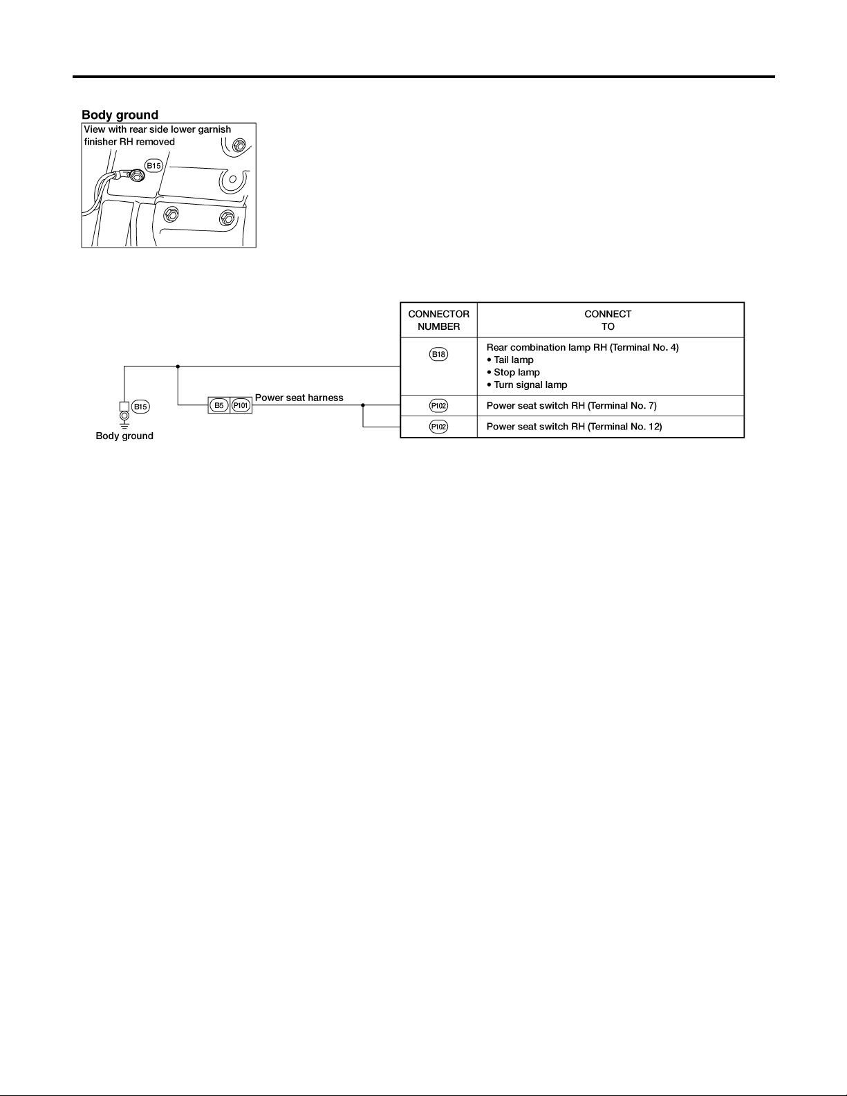
Ground is supplied to the rear combination lamp RH terminal 4 through body ground B15.
Ground is supplied to combination meter terminal 22 through body grounds M68, M105 and M130.
With power and ground supplied, the combination flasher unit controls the flashing of the RH turn signal lamps.
HAZARD LAMP OPERATION
NDEL0029S04
Power is supplied at all times to hazard switch terminal 3 through:
쐌 10A fuse (No. 23, located in the fuse block).
With the hazard switch in the ON position, power is supplied
쐌 through terminal 1 of the hazard switch
쐌 to combination flasher unit terminal 1
쐌 through terminal 3 of the combination flasher unit
쐌 to hazard switch terminal 5.
Ground is supplied to combination flasher unit terminal 2 through body grounds M68, M105 and M130.
Power is supplied through terminal 4 of the hazard switch to
쐌 front turn signal lamp LH terminal 3
쐌 combination meter terminal 15
쐌 rear combination lamp LH terminal 2.
Power is supplied through terminal 6 of the hazard switch to
쐌 front turn signal lamp RH terminal 3
쐌 combination meter terminal 21
쐌 rear combination lamp RH terminal 2.
Ground is supplied to each lamp in the same manner as for LH or RH turn operation.
With power and ground supplied, the combination flasher unit controls the flashing of hazard warning lamps.
EL-58
Page 59

TURN SIGNAL AND HAZARD WARNING LAMPS
Wiring Diagram — TURN —
Wiring Diagram — TURN —
NDEL0030
GI
MA
EM
LC
EC
FE
AT
AX
SU
BR
ST
RS
BT
HA
SC
IDX
EL-59
WEL195
Page 60

TURN SIGNAL AND HAZARD WARNING LAMPS
Wiring Diagram — TURN — (Cont’d)
EL-60
AEL722B
Page 61

TURN SIGNAL AND HAZARD WARNING LAMPS
Trouble Diagnoses
Symptom Possible cause Repair order
Turn signal and hazard warning
lamps do not operate.
Turn signal lamps do not operate
but hazard warning lamps operate.
Hazard warning lamps do not operate but turn signal lamps operate.
Front turn signal lamp LH or RH
does not operate.
Rear turn signal lamp LH does not
operate.
Rear turn signal lamp RH does not
operate.
Trouble Diagnoses
1. Hazard switch
2. Combination flasher unit
3. Open in combination flasher
unit circuit
1. 10A fuse
2. Hazard switch
3. Turn signal switch
4. Open in turn signal switch circuit
1. 10A fuse
2. Hazard switch
3. Open in hazard switch circuit
1. Bulb
2. Grounds E3, E30 and E50
1. Bulb
2. Grounds M68, M105 and M130
1. Bulb
2. Ground B15
NDEL0031
1. Check hazard switch.
2. Refer to combination flasher unit check.
3. Check wiring to combination flasher unit for open
circuit.
1. Check 10A fuse (No. 27, located in fuse block). Turn
ignition switch ON and verify battery positive voltage
is present at terminal 2 of hazard switch.
2. Check hazard switch.
3. Check turn signal switch.
4. Check PU wire between combination flasher unit
and turn signal switch for open circuit.
1. Check 10A fuse (No. 23, located in fuse block).
Verify battery positive voltage is present at terminal
3 of hazard switch.
2. Check hazard switch.
3. Check PU wire between combination flasher unit
and hazard switch for open circuit.
1. Check bulb.
2. Check grounds E3, E30 and E50.
1. Check bulb.
2. Check grounds M68, M105 and M130.
1. Check bulb.
2. Check ground B15.
GI
MA
EM
LC
EC
FE
AT
AX
SU
LH and RH turn indicators do not
operate.
LH or RH turn indicator does not
operate.
1. Grounds M68, M105 and M130 1. Check grounds M68, M105 and M130.
1. Bulb 1. Check bulb in combination meter.
Electrical Components Inspection
COMBINATION FLASHER UNIT CHECK
쐌 Before checking, ensure that bulbs meet specifications.
쐌 Connect a battery and test lamp to the combination flasher
unit, as shown. Combination flasher unit is properly functioning if it blinks when power is supplied to the circuit.
SEL122E
NDEL0032
NDEL0032S01
BR
ST
RS
BT
HA
SC
IDX
EL-61
Page 62

System Description
TRAILER TOW
System Description
TRAILER TAIL LAMP OPERATION
NDEL0035
NDEL0035S01
With the lighting switch in the 1ST or 2ND position, the tail lamp relay is energized and power is supplied
쐌 from tail lamp relay terminal 5
쐌 through 10A fuse (No. 19, located in the fuse block)
쐌 to trailer harness connector terminal 2.
Ground is supplied to trailer tow control unit terminal 2 and trailer harness connector terminal 1 through body
grounds M68, M105 and M130.
With power and ground supplied, the trailer tail lamps will illuminate.
TRAILER STOP, TURN SIGNAL AND HAZARD LAMP OPERATION
NDEL0035S02
The trailer stop, turn signal and hazard lamps are all controlled by the trailer tow control unit. The trailer tow
control unit regulates the amount of voltage supplied to the trailer lamps. If either turn signal or the hazard
lamps are turned on and the control unit gets a brake lamp input, the control unit supplies more voltage to the
trailer lamps to make them illuminate brighter.
Power is supplied to trailer tow control unit terminals 3 and 4 through 20A fuse (No. 22, located in the fuse
block) at all times.
Stop lamp input is supplied to trailer tow control unit terminal 1.
Left turn signal and hazard lamp input is supplied to trailer tow control unit terminal 7.
Right turn signal and hazard lamp input is supplied to trailer tow control unit terminal 8.
Based on the stop lamp, turn signal lamp and hazard lamp inputs to the trailer tow control unit, power is supplied to trailer LH stop/turn lamp:
쐌 from trailer tow control unit terminal 6
쐌 to trailer harness connector terminal 3.
Power is also supplied to trailer RH stop/turn lamp:
쐌 from trailer tow control unit terminal 5
쐌 to trailer harness connector terminal 4.
EL-62
Page 63

TRAILER TOW
Wiring Diagram — T/TOW —
Wiring Diagram — T/TOW —
NDEL0036
GI
MA
EM
LC
EC
FE
AT
AX
SU
BR
ST
RS
BT
HA
SC
IDX
EL-63
WEL197
Page 64

Trouble Diagnoses
TRAILER TOW
Trouble Diagnoses
TRAILER TOW CONTROL UNIT INSPECTION TABLE
Terminal
No.
1 Y/B Stop lamps signal
2 B Ground ——
3 R/W Power supply — 12
4 R/W Power supply — 12
5 G Stop/RH turn lamp (output)
6 Y Stop/LH turn lamp (output)
7 R/G LH turn lamps
Wire
color
Item Condition
When brake pedal is depressed 12
When brake pedal is released 0
When brake pedal is depressed 12
When RH turn lamps or hazard lamps operate 12 (intermittently)
All other conditions 0
When brake pedal is depressed 12
When LH turn lamps or hazard lamps operate 12 (intermittently)
All other conditions 0
When LH turn lamps or hazard lamps operate 12 (intermittently)
All other conditions 0
Voltage
(Approximate
value)
NDEL0037
NDEL0037S01
8 R/W RH turn lamps
When RH turn lamps or hazard lamps operate 12 (intermittently)
All other conditions 0
AEL864B
EL-64
Page 65

ILLUMINATION
System Description
System Description
Power is supplied at all times
쐌 through 7.5A fuse (No. 39, located in the fuse and fusible link box)
쐌 to smart entrance control unit terminal 13.
Power is supplied at all times
쐌 to tail lamp relay terminals 2 and 3.
With the ignition switch in the ACC or ON position, power is supplied
쐌 through 7.5A fuse (No. 5, located in the fuse block)
쐌 to door mirror remote control switch terminal 1.
Ground is supplied to smart entrance control unit terminal 10 through body grounds M68, M105 and M130.
With the lighting switch in the 1ST or 2ND position, the tail lamp relay is energized and power is supplied
쐌 from tail lamp relay terminal 5
쐌 through 7.5A fuse (No. 18, located in the fuse block)
쐌 to power terminal on all illuminated components except door mirror remote control switch.
For auto lamp operation (if equipped), ground is supplied to tail lamp relay through headlamp control unit terminal 12 to energize tail lamp relay. Then tail lamp relay supplies power to turn on parking, license, tail lamps
and illumination. For detailed information on autolamp operation, refer to “HEADLAMP (USA)”, EL-32 or
“HEADLAMP (FOR CANADA) — DAYTIME LIGHT SYSTEM, EL-46.
The illumination control switch in combination with the smart entrance control unit control the amount of current flow through the illumination system. This is accomplished by varying the amount of ground supplied to
the illumination system.
When the illumination control switch is pushed in the LIGHTER direction, ground is supplied
쐌 to smart entrance control unit terminal 42
쐌 through illumination control switch terminal 5
쐌 from illumination control switch terminal 8
쐌 through body grounds M68, M105 and M130.
When the illumination control switch is pushed in the DARKER direction, ground is supplied
쐌 to smart entrance control unit terminal 33
쐌 through illumination control switch terminal 2
쐌 from illumination control switch terminal 8
쐌 through body grounds M68, M105 and M130.
Ground is supplied to the illumination system from smart entrance control unit terminal 11 through smart
entrance control unit terminal 10.
The rear audio remote control unit illumination is not controlled by the illumination control switch. The intensity of this lamp does not change. Rear audio remote control unit terminal 10 is grounded directly through body
grounds M68, M105 and M130.
The following chart indicates power and ground terminals for the illumination system components.
NDEL0038
GI
MA
EM
LC
EC
FE
AT
AX
SU
BR
ST
RS
BT
HA
Component Connector No. Power terminal Ground Terminal
Audio unit M45 21 22
Combination meter M16, M17 23 and 10 24 and 11
ASCD main switch M6 5 6
Illumination control switch and autolamp switch M8 1 7
Lighting switch M7 1 2
Main power window and door lock/unlock switch D14 3 10
Door lock/unlock switch RH D109 1 6
Front power window switch RH D108 1 6
Rear audio remote control unit M115 9 10
Rear fan switch (rear)* B6 1 2
A/C control unit (without EATC) M37, M34 1 and 7 2 and 1
EL-65
SC
IDX
Page 66

ILLUMINATION
System Description (Cont’d)
Component Connector No. Power terminal Ground Terminal
EATC unit* M33 6 1
Hazard switch M23 7 8
Rear window defogger switch M22 6 5
Rear fan switch (front)* M32 2 3
Ash tray M77 1 2
Rear wiper switch M21 3 2
Door mirror remote control switch* D9 1 3
* If equipped.
EL-66
Page 67

ILLUMINATION
Schematic
Schematic
NDEL0040
GI
MA
EM
LC
EC
FE
AT
AX
SU
BR
ST
RS
BT
HA
SC
IDX
EL-67
WEL198
Page 68

Wiring Diagram — ILL —
ILLUMINATION
Wiring Diagram — ILL —
NDEL0041
EL-68
WEL199
Page 69

ILLUMINATION
Wiring Diagram — ILL — (Cont’d)
GI
MA
EM
LC
EC
FE
AT
AX
SU
BR
ST
RS
BT
HA
SC
EL-69
IDX
WEL200
Page 70

Wiring Diagram — ILL — (Cont’d)
ILLUMINATION
EL-70
WEL201
Page 71

ILLUMINATION
Wiring Diagram — ILL — (Cont’d)
GI
MA
EM
LC
EC
FE
AT
AX
SU
BR
ST
RS
BT
HA
SC
EL-71
IDX
WEL202
Page 72

System Description
INTERIOR ROOM LAMP
System Description
OUTLINE
NDEL0039
NDEL0039S01
Interior room lamps other than vanity lamp LH/RH (and map lamp when switch is in ON position) are controlled by the smart entrance control unit corresponding to the following signals
쐌 Ignition switch (Power supply signal to smart entrance control unit terminal 43)
쐌 Key switch (Ground signal to smart entrance control unit terminal 35)
쐌 Lighting switch (Momentary ground signal to smart entrance control unit terminal 32)
쐌 Front door switch LH/RH, sliding door switch LH/RH, back doorlatch switch LH/RH (Ground signal to smart
entrance control unit terminal 9, 24, 34 or 41)
쐌 Multi-remote controller.
Power is supplied at all times
쐌 through 15A fuse (No. 21, located in the fuse block)
쐌 to all interior room lamps.
Ground is supplied to the controlled interior room lamps
쐌 through smart entrance control unit terminal 5 (Zone A)
쐌 through smart entrance control unit terminal 4 (Zone B) or
쐌 through smart entrance control unit terminal 6 (Zone C).
Controlled interior room lamps are grouped as zone A, B or C depending on connected smart entrance control unit terminals as follows
쐌 Map lamp (Zone A, when its switch is in DOOR position)
쐌 Front/rear room lamp (Zone B, when its switch is in DOOR position or Zone C, when its switch is in ON
position)
쐌 Front/rear personal lamps (Zone B, when its switch is in DOOR position or Zone C, when its switch is in
ON position)
쐌 Front step lamp LH/RH (Zone A)
쐌 Foot lamp LH/RH (Zone A)
쐌 Sliding door step lamp LH/RH (Zone B)
쐌 Back door lamp (Zone B)
쐌 Glove box lamp (Zone C, when glove box lid is opened).
Vanity lamp LH/RH are not controlled by the smart entrance control unit. They turn on and off corresponding
to the switch position on the lamp.
When the vanity lamp LH/RH or map lamp switch is turned on, ground is supplied
쐌 to vanity lamp LH/RH or map lamp terminal 2.
With power and ground supplied, the operated lamp turns on.
OPERATION
NDEL0039S02
Interior room lamps turn on when
쐌 key switch REMOVED (ignition key removed from ignition key cylinder)
쐌 any door is opened
쐌 lighting switch is pushed (momentary on switch)
쐌 unlock signal is transmitted from multi-remote controller (only for zone A and B).
Zone C interior room lamps will turn off when the last door is closed. Zone A and B interior room lamps will
remain fully illuminated for 1 second. After 1 second, zone A and B interior room lamps are lit at half illumination for approximately 10 seconds. Finally the interior room lamps will gradually fade away over approximately the next 5 seconds.
Interior room lamps will turn off immediately during the above timer operation when
쐌 ignition switch is turned to ON position
쐌 lock signal is transmitted from multi-remote controller
쐌 lighting switch is pushed (momentary on switch).
If the interior room lamps are turned on by pushing the lighting switch (momentary on switch), they can be
turned off by pushing the lighting switch again.
EL-72
Page 73

INTERIOR ROOM LAMP
System Description (Cont’d)
BATTERY SAVER
If any of the lamps controlled by smart entrance control unit remain on for an extended period of time, the
smart entrance control unit will turn off the lamps to save the battery consumption by opening the ground
circuit.
NDEL0039S03
GI
MA
EM
LC
EC
FE
AT
AX
SU
BR
ST
RS
BT
HA
SC
IDX
EL-73
Page 74

Schematic
INTERIOR ROOM LAMP
Schematic
NDEL0042
EL-74
WEL203
Page 75

INTERIOR ROOM LAMP
Wiring Diagram — INT/L —
Wiring Diagram — INT/L —
NDEL0043
GI
MA
EM
LC
EC
FE
AT
AX
SU
BR
ST
RS
BT
HA
SC
IDX
EL-75
WEL204
Page 76

Wiring Diagram — INT/L — (Cont’d)
INTERIOR ROOM LAMP
EL-76
WEL205
Page 77

INTERIOR ROOM LAMP
Wiring Diagram — INT/L — (Cont’d)
GI
MA
EM
LC
EC
FE
AT
AX
SU
BR
ST
RS
BT
HA
SC
EL-77
IDX
WEL206
Page 78

Trouble Diagnoses
INTERIOR ROOM LAMP
Trouble Diagnoses
SYMPTOM: Interior room lamp does not turn on or off properly.
1 CHECK INTERIOR ROOM LAMP FUSE
Check 15 A fuse (No. 21, located in fuse block).
OK or NG
OK 䊳 GO TO 2.
NG 䊳 Replace fuse and check harness for short between fuse and interior room lamps.
2 CHECK LIGHTING SWITCH (INTERIOR) SIGNAL
1. Close all doors, turn ignition switch to ON position and push lighting switch.
Do interior room lamps turn on?
2. Push lighting switch again.
Do interior room lamps turn off?
OK or NG
OK 䊳 GO TO 3.
NG 䊳 Check the following.
쐌 Lighting switch
쐌 Lighting switch ground circuit
쐌 Harness for open or short between lighting switch and smart entrance control unit
NDEL0044
3 CHECK INTERIOR ROOM LAMP POWER SUPPLY
Check voltage between room lamp terminals and ground
OK or NG
OK 䊳 GO TO 4.
NG 䊳 Check harness for open between fuse and interior room lamps.
AEL867B
AEL868B
EL-78
Page 79

INTERIOR ROOM LAMP
4 CHECK INTERIOR ROOM LAMP BULB
Check interior room lamp bulb.
OK 䊳 GO TO 5.
NG 䊳 Replace bulb.
Trouble Diagnoses (Cont’d)
GI
OK or NG
MA
5 CHECK KEY SWITCH (INSERTED) AND IGNITION ON SIGNAL
1. Insert key into ignition key cylinder.
2. Open front door LH.
Does warning chime sound?
3. Turn ignition key to ON position.
Does warning chime stop sounding?
OK or NG
OK 䊳 GO TO 6.
NG 䊳 Check “WARNING CHIME” system, refer to EL-100.
6 CHECK DOOR SWITCH INPUT SIGNAL
Check voltage between smart entrance control unit terminals and ground.
EM
LC
EC
FE
AT
AX
SU
BR
ST
AEL869B
WEL547A
OK or NG
OK 䊳 Check harness for open or short between smart entrance control unit and interior room
lamps.
NG 䊳 Check the following.
쐌 Door switch
쐌 Door switch ground condition
쐌 Harness for open or short between door switch and smart entrance control unit
RS
BT
HA
SC
IDX
EL-79
Page 80

METERS AND GAUGES
Component Parts and Harness Connector Location
Component Parts and Harness Connector
Location
NDEL0045
WEL223
System Description
POWER SUPPLY AND GROUND CIRCUIT
NDEL0046
NDEL0046S01
With the ignition switch in the ON or START position, power is supplied
쐌 through 10A fuse (No. 29, located in the fuse block)
쐌 to combination meter terminals 14 and 33.
Ground is supplied
쐌 to combination meter terminals 17 and 30
쐌 through body ground M51.
WATER TEMPERATURE GAUGE
NDEL0046S02
The water temperature gauge indicates the engine coolant temperature. The reading on the gauge is based
on the resistance of the thermal transmitter.
As the temperature of the coolant increases, the resistance of the thermal transmitter decreases. A variable
ground is supplied to terminal 13 of the combination meter for the water temperature gauge. The needle on
the gauge moves from “C” to “H”.
TACHOMETER
NDEL0046S03
The tachometer indicates engine speed in revolutions per minute (rpm).
The tachometer is regulated by a signal
쐌 from terminal 3 of the ECM
쐌 to combination meter terminal 29 for the tachometer.
FUEL GAUGE
NDEL0046S04
The fuel gauge indicates the approximate fuel level in the fuel tank.
The fuel gauge is regulated by a variable ground signal supplied
쐌 to combination meter terminal 20 for the fuel gauge
쐌 from terminal 5 of the fuel level sensor unit
쐌 through terminal 6 of the fuel level sensor unit and
쐌 through body grounds M68, M105 and M130.
SPEEDOMETER
The vehicle speed sensor sends a voltage signal to the combination meter for the speedometer.
Pulsed ground is supplied
쐌 to combination meter terminal 32 for the speedometer
EL-80
NDEL0046S05
Page 81

METERS AND GAUGES
쐌 from terminal 1 of the vehicle speed sensor.
The speedometer converts the pulsed ground into the vehicle speed displayed.
System Description (Cont’d)
GI
MA
EM
LC
EC
FE
AT
AX
SU
BR
ST
RS
BT
HA
SC
EL-81
IDX
Page 82

Combination Meter
METERS AND GAUGES
Combination Meter
NDEL0047
EL-82
WEL317
Page 83

METERS AND GAUGES
Combination Meter (Cont’d)
GI
MA
EM
LC
EC
FE
AT
AX
SU
BR
ST
RS
BT
HA
SC
EL-83
IDX
WEL318
Page 84

Wiring Diagram — METER —
METERS AND GAUGES
Wiring Diagram — METER —
NDEL0048
EL-84
WEL207
Page 85

METERS AND GAUGES
Trouble Diagnoses
Trouble Diagnoses
SYMPTOM CHART
Symptom Diagnoses procedure Reference page
Speedometer is malfunctioning. POWER SUPPLY AND GROUND CIRCUIT CHECK EL-85
INSPECTION/VEHICLE SPEED SENSOR EL-86
Tachometer is malfunctioning. INSPECTION/ENGINE REVOLUTION SIGNAL EL-88
Fuel tank gauge is malfunctioning. POWER SUPPLYAND GROUND CIRCUIT CHECK EL-85
INSPECTION/FUEL LEVEL SENSOR UNIT EL-89
Water temperature gauge is malfunc-
tioning.
POWER SUPPLY AND GROUND CIRCUIT CHECK EL-85
INSPECTION/THERMAL TRANSMITTER EL-90
POWER SUPPLY AND GROUND CIRCUIT CHECK
Power Supply Circuit Check
Terminals Ignition switch position
(+) (– ) OFF ON START
NDEL0049S0201
NDEL0049
NDEL0049S01
NDEL0049S02
GI
MA
EM
LC
EC
FE
AT
AX
SU
BR
AEL942B
AEL943B
14 Ground 0 V
33 Ground 0 V
Battery
voltage
Battery
voltage
Battery
voltage
Battery
voltage
If NG, check the following
쐌 10A fuse (No. 29, located in fuse block)
쐌 Harness for open or short between fuse and combination
meter.
ST
RS
BT
HA
SC
IDX
EL-85
Page 86

Trouble Diagnoses (Cont’d)
METERS AND GAUGES
Ground Circuit Check
Terminals Continuity
17 - Ground Yes
30 - Ground Yes
AEL944B
AEL173C
INSPECTION/VEHICLE SPEED SENSOR
1 CHECK VEHICLE SPEED SENSOR OUTPUT
1. Remove vehicle speed sensor from transaxle.
2. Check voltage between combination meter terminals 30 and 32 while quickly turning speed sensor pinion.
NDEL0049S0202
NDEL0049S03
Voltage: Approx. 0.5 V
OK or NG
OK 䊳 Vehicle speed sensor is OK.
NG 䊳 GO TO 2.
EL-86
AEL945B
Page 87

METERS AND GAUGES
Trouble Diagnoses (Cont’d)
2 CHECK VEHICLE SPEED SENSOR
Check resistance between vehicle speed sensor terminals 1 and 2.
Resistance: Approx. 250Ω
OK or NG
OK 䊳 Check harness or connector between speedometer and vehicle speed sensor.
NG 䊳 Replace vehicle speed sensor.
GI
MA
EM
LC
AEL757A
EC
FE
AT
AX
SU
BR
ST
RS
BT
HA
SC
EL-87
IDX
Page 88

Trouble Diagnoses (Cont’d)
METERS AND GAUGES
INSPECTION/ENGINE REVOLUTION SIGNAL
1 CHECK ECM OUTPUT
1. Start engine.
2. Check voltage between combination meter terminals 29 and 30 at idle and 2,000 rpm.
Higher rpm = Higher voltage
Lower rpm = Lower voltage
Voltage should change with rpm.
OK or NG
OK 䊳 Engine revolution signal is OK.
NG 䊳 Check harness for open or short between ECM and combination meter.
=NDEL0049S04
AEL946B
EL-88
Page 89

METERS AND GAUGES
Trouble Diagnoses (Cont’d)
INSPECTION/FUEL LEVEL SENSOR UNIT
1 CHECK GAUGE OPERATION
1. Disconnect fuel level sensor unit connector.
2. Turn ignition switch ON.
3. Check gauge operation.
Gauge should move smoothly to full scale.
4. Connect terminals 5 and 6 with wire for less than 10 seconds.
5. Check gauge operation.
Gauge should move smoothly to empty scale.
OK or NG
OK 䊳 GO TO 2.
NG 䊳 Check the following.
쐌 Low fuel/anti-slosh unit
쐌 Combination meter
=NDEL0049S05
WEL235
GI
MA
EM
LC
EC
FE
AT
AX
SU
2 CHECK GAUGE UNITS
Refer to “FUEL LEVEL SENSOR UNIT CHECK”, EL-90.
OK or NG
OK 䊳 Fuel level sensor is OK.
NG 䊳 Replace fuel level sensor unit.
BR
ST
RS
BT
HA
SC
IDX
EL-89
Page 90

Trouble Diagnoses (Cont’d)
METERS AND GAUGES
INSPECTION/THERMAL TRANSMITTER
1 CHECK THERMAL TRANSMITTER
Refer to “THERMAL TRANSMITTER CHECK”, EL-91.
OK or NG
OK 䊳 GO TO 2.
NG 䊳 Replace thermal transmitter.
2 CHECK HARNESS FOR OPEN OR SHORT
1. Disconnect combination meter connector and thermal transmitter connector.
2. Check continuity between combination meter terminal 13 and thermal transmitter terminal 1.
Continuity should exist.
3. Check continuity between combination meter terminal 13 and ground.
Continuity should not exist.
=NDEL0049S06
OK or NG
OK 䊳 Thermal transmitter is OK.
NG 䊳 Repair harness or connector.
Electrical Component Inspection
FUEL LEVEL SENSOR UNIT CHECK
쐌 For removal, refer to “FUEL PUMP AND GAUGE”, FE-6.
Check the resistance between terminals 5 and 6.
Ohmmeter
(+) (– )
AEL513B
56
AEL947B
NDEL0050
NDEL0050S01
Float position
mm (in)
*3 Full 22.5 (0.89) Approx. 160.0
*2 1/2 81.3 (3.20) Approx. 84.0
*1 Empty
150.5
(5.93)
Resistance
value
(Ω)
Approx. 15.0
EL-90
Page 91

METERS AND GAUGES
Electrical Component Inspection (Cont’d)
MEL424F
AEL096A
THERMAL TRANSMITTER CHECK
Check the resistance between the terminals of thermal transmitter
and body ground.
Water temperature Resistance value
75°C (167°F) Approx. 179 - 219 Ω
100°C (212°F) Approx. 60 - 72 Ω
VEHICLE SPEED SENSOR SIGNAL CHECK
1. Remove vehicle speed sensor from transaxle.
2. Turn vehicle speed sensor pinion quickly and measure voltage
across terminals 1 and 2.
NDEL0050S02
NDEL0050S03
GI
MA
EM
LC
EC
FE
AT
AX
SU
BR
ST
RS
BT
HA
SC
IDX
EL-91
Page 92

System Description
WARNING LAMPS
System Description
POWER SUPPLY AND GROUND CIRCUIT
NDEL0051
NDEL0051S01
With the ignition switch in the ON or START position, power is supplied
쐌 through 10A fuse (No. 29, located in the fuse block)
쐌 to combination meter terminals 33, 14, 8 and
쐌 bulb check relay terminal 1.
Ground is supplied
쐌 to combination meter terminal 12,
쐌 fuel tank gauge unit terminal 6 and
쐌 seat belt buckle switch terminal 2
쐌 through body ground M68, M105 and M130.
Ground is supplied to combination meter terminal 17 through body ground M51.
Ground is supplied
쐌 to bulb check relay terminal 3,
쐌 brake fluid level switch terminal 2 and
쐌 washer fluid level switch terminal 1
쐌 through body grounds E3, E30 and E50.
AIR BAG WARNING LAMP
NDEL0051S02
During prove out or when an air bag malfunction occurs, the ground path is interrupted
쐌 from the air bag diagnosis sensor unit terminal 15
쐌 to combination meter terminal 7.
Ground is then supplied
쐌 to combination meter terminal 12
쐌 through body grounds M68, M105 and M130.
With power and ground supplied, the air bag warning lamp (LEDs) illuminates or flashes. For further
information, refer to RS section.
O/D OFF INDICATOR LAMP
NDEL0051S03
During prove out or when overdrive is cancelled, ground is supplied
쐌 to combination meter terminal 28
쐌 from TCM (transmission control module) terminal 13.
With power and ground supplied, O/D off indicator lamp illuminates.
When TCM detects malfunctioning, the indicator flashes. For further information, refer to AT-35.
LOW FUEL LEVEL WARNING LAMP
NDEL0051S04
The amount of fuel in the fuel tank is determined by a float in the tank.A signal is sent from fuel level sensor
terminal 5 to combination meter terminal 20. The low fuel/anti-slosh unit will illuminate the low fuel level warning lamp when the fuel level is low.
DOOR AJAR WARNING LAMP
NDEL0051S05
When a door is open, ground is supplied to the smart entrance control unit at terminals 9, 24, 34 or 41.
Ground is then supplied
쐌 to combination meter terminal 5
쐌 from smart entrance control unit terminal 14.
With power and ground supplied, the door ajar warning lamp illuminates.
LOW WASHER FLUID LEVEL WARNING LAMP
NDEL0051S06
When the washer fluid level is low, ground is supplied
쐌 to combination meter terminal 34
쐌 from washer fluid level switch terminal 2.
With power and ground supplied, the low washer fluid level warning lamp illuminates.
EL-92
Page 93

WARNING LAMPS
System Description (Cont’d)
LOW OIL PRESSURE WARNING LAMP
Low oil pressure, causes the oil pressure switch terminal 1 to provide ground to combination meter
terminal 4.
With power and ground supplied, the low oil pressure warning lamp illuminates.
BRAKE WARNING LAMP
When the parking brake is applied or the brake fluid level is low, ground is supplied
쐌 to combination meter terminal 3
쐌 from parking brake switch terminal 1 or
쐌 brake fluid level switch terminal 1.
With power and ground supplied, the brake warning lamp illuminates.
CHARGE WARNING LAMP
During prove out or when a generator malfunction occurs, ground is supplied
쐌 to combination meter terminal 9
쐌 from generator terminal 3.
With power and ground supplied, the charge warning lamp illuminates.
BULB CHECK RELAY (BRAKE WARNING LAMP PROVE OUT)
When the ignition switch is in the ON or START position, and with the engine not running, ground is supplied
쐌 to bulb check relay terminal 2
쐌 from generator terminal 3.
With power and ground supplied, the bulb check relay is energized, providing a ground path for the brake
warning lamp. With power and ground supplied, the brake warning lamp illuminates.
SEAT BELT WARNING LAMP
When the driver’s seat belt is unfastened, ground is supplied
쐌 to combination meter terminal 2
쐌 from seat belt buckle switch terminal 1.
With power and ground supplied, the seat belt warning lamp illuminates.
MALFUNCTION INDICATOR LAMP
During prove out or when an engine control malfunction occurs, ground is supplied
쐌 to combination meter terminal 27
쐌 from ECM terminal 18.
With power and ground supplied, the malfunction indicator lamp illuminates.
For further information, refer to EC-65.
NDEL0051S07
NDEL0051S08
NDEL0051S09
NDEL0051S10
NDEL0051S11
NDEL0051S12
GI
MA
EM
LC
EC
FE
AT
AX
SU
BR
ST
RS
BT
ABS WARNING LAMP
During prove out or when an ABS malfunction occurs, ground is interrupted
쐌 to combination meter terminal 25
쐌 from ABS actuator and electric unit (control unit) terminal 21.
With power and ground supplied, the ABS warning lamp illuminates.
For further information, refer to BR-31.
EL-93
NDEL0051S13
HA
SC
IDX
Page 94

Schematic
WARNING LAMPS
Schematic
NDEL0052
EL-94
WEL208
Page 95

WARNING LAMPS
Wiring Diagram — WARN —
Wiring Diagram — WARN —
NDEL0053
GI
MA
EM
LC
EC
FE
AT
AX
SU
BR
ST
RS
BT
HA
SC
IDX
EL-95
WEL209
Page 96

Wiring Diagram — WARN — (Cont’d)
WARNING LAMPS
EL-96
WEL210
Page 97

WARNING LAMPS
Wiring Diagram — WARN — (Cont’d)
GI
MA
EM
LC
EC
FE
AT
AX
SU
BR
ST
RS
BT
HA
SC
EL-97
IDX
WEL211
Page 98

Wiring Diagram — WARN — (Cont’d)
WARNING LAMPS
EL-98
WEL212
Page 99

WARNING LAMPS
Electrical Component Inspection
MEL425F
SEL901F
Electrical Component Inspection
FUEL WARNING LAMP SENSOR CHECK
NDEL0054
NDEL0054S01
쐌 The low fuel level warning lamp is controlled by the low fuel/
anti-slosh unit, which is built into the combination meter. If the
low fuel level warning lamp fails to illuminate, first check the
fuel level sensor unit, refer to “INSPECTION/FUEL LEVEL
SENSOR UNIT” EL-89. If the fuel level sensor unit is operating properly, inspect the low fuel level warning lamp bulb and
anti-slosh unit for proper function.
OIL PRESSURE SWITCH CHECK
Engine start
Engine stop
Oil pressure
kPa (kg/cm
More than 10 - 20
(0.1-0.2,1-3)
Less than 10 - 20
(0.1-0.2,1-3)
2
, psi)
NDEL0054S02
Continuity
NO
YES
Check the continuity between the terminals of oil pressure switch
and body ground.
DIODE CHECK
NDEL0054S03
쐌 Check continuity using an ohmmeter.
쐌 Diode is functioning properly if test results are as shown in the
figure at left.
쐌 Check diodes at the combination meter harness connector
instead of on the combination meter assembly. Refer to “Wiring Diagram—WARN—”, EL-95.
NOTE:
Specifications may vary depending on the type of tester.
Before performing this inspection, be sure to refer to the
instruction manual for your tester.
GI
MA
EM
LC
EC
FE
AT
AX
SU
BR
ST
RS
EL-99
BT
HA
SC
IDX
Page 100

WARNING CHIME
Component Parts and Harness Connector Location
Component Parts and Harness Connector
Location
NDEL0055
WEL281
System Description
POWER SUPPLY AND GROUND CIRCUIT
NDEL0056
NDEL0056S01
The warning chime is integrated with the smart entrance control unit, which controls its operation.
Power is supplied at all times
쐌 through 7.5A fuse (No. 39, located in the fuse and fusible link box)
쐌 to smart entrance control unit terminal 13.
With the ignition switch in the ON or START position, power is supplied
쐌 through 10A fuse (No. 30, located in the fuse block)
쐌 to smart entrance control unit terminal 43.
Ground is supplied to smart entrance control unit terminal 10 through body grounds M68, M105 and M130.
When a signal, or combination of signals, is received by the smart entrance control unit, the warning chime
will sound.
IGNITION KEY WARNING CHIME
NDEL0056S02
With the key in and the ignition switch in the OFF or ACC position, and the front door LH open, the warning
chime will sound. Ground is supplied
쐌 from key switch terminal 1
쐌 to smart entrance control unit terminal 35 and
쐌 from front door switch LH terminal 2
쐌 to smart entrance control unit terminal 34.
Key switch terminal 2 is grounded through body grounds E3, E30 and E50.
LIGHT WARNING CHIME
NDEL0056S03
With ignition switch OFF or ACC, front door LH open, and lighting switch in 1STor 2ND position,warning chime
will sound. Ground is supplied
쐌 from lighting switch terminal 3
쐌 to smart entrance control unit terminal 26 and
쐌 from front door switch LH terminal 2
쐌 to smart entrance control unit terminal 34.
Lighting switch terminal 7 is grounded through body grounds M68, M105 and M130.
EL-100
 Loading...