

Page 1

ENGINE
Revision: July 2007 2008 Maxima
A
FL
SECTION FL
CONTENTS
SERVICE INFORMATION ............................2
PRECAUTIONS ...................................................2
Precaution for Supplemental Restrain t System
(SRS) "AIR BAG" and "SEAT BELT PRE-TEN-
SIONER" ...................................................................
PREPARATION ...................................................3
Special Service Tool ................................. ... .... .........3
Commercial Service Tool ..........................................3
FUEL SYSTEM .................................................... 4
Checking Fuel Line ...................................................4
FUEL SYSTEM
General Precaution ................................................... 4
FUEL LEVEL SENSOR UNIT, FUEL FILTER
AND FUEL PUMP ASSEMBLY .........................
Removal and Installation .......................................... 6
2
Disassembly and Assembly ...................................... 9
FUEL TANK ......................................................11
Removal and Installation .........................................11
SERVICE DATA AND SPECIFICATIONS
(SDS) .................................................................
Standard and Limit ... .... ... ........................................15
15
C
D
E
F
6
G
H
I
J
K
M
N
O
P
L
FL-1
Page 2

PRECAUTIONS
Revision: July 2007 2008 Maxima
< SERVICE INFORMATION >
SERVICE INFORMATION
PRECAUTIONS
Precaution for Supplemental Restraint System (SRS) "AIR BAG" and "SEAT BELT PRE-TENSIONER" INFOID:0000000001720987
The Supplemental Restraint System such as “AIR BAG” and “SEAT BELT PRE-TENSIONER”, used along
with a front seat belt, helps to reduce the risk or severity of injury to the driver and front passenger for certain
types of collision. This system includes seat belt switch inputs and dual stage front air bag modules. The SRS
system uses the seat belt switches to determine the front air bag deployment, and may only deploy one front
air bag, depending on the severity of a collision and whether the front occupants are belted or unbelted.
Information necessary to service the system safely is included in the SRS and SB section of this Service Manual.
WARNING:
• To avoid rendering the SRS inoperative, which could increase the risk of personal injury or death in
the event of a collision which would result in air bag inflation, all maintenance must be performed by
an authorized NISSAN/INFINITI dealer.
• Improper maintenance, including incorrect removal and installation of the SRS, can lead to personal
injury caused by unintentional activation of the system. For removal of Spiral Cable and Air Bag
Module, see the SRS section.
• Do not use electrical test equipment on any circuit related to the SRS unless instructed to in this
Service Manual. SRS wiring harnesses can be identified by yellow and/or orange harnesses or harness connectors.
FL-2
Page 3
< SERVICE INFORMATION >
Revision: July 2007 2008 Maxima
PREPARATION
PREPARATION
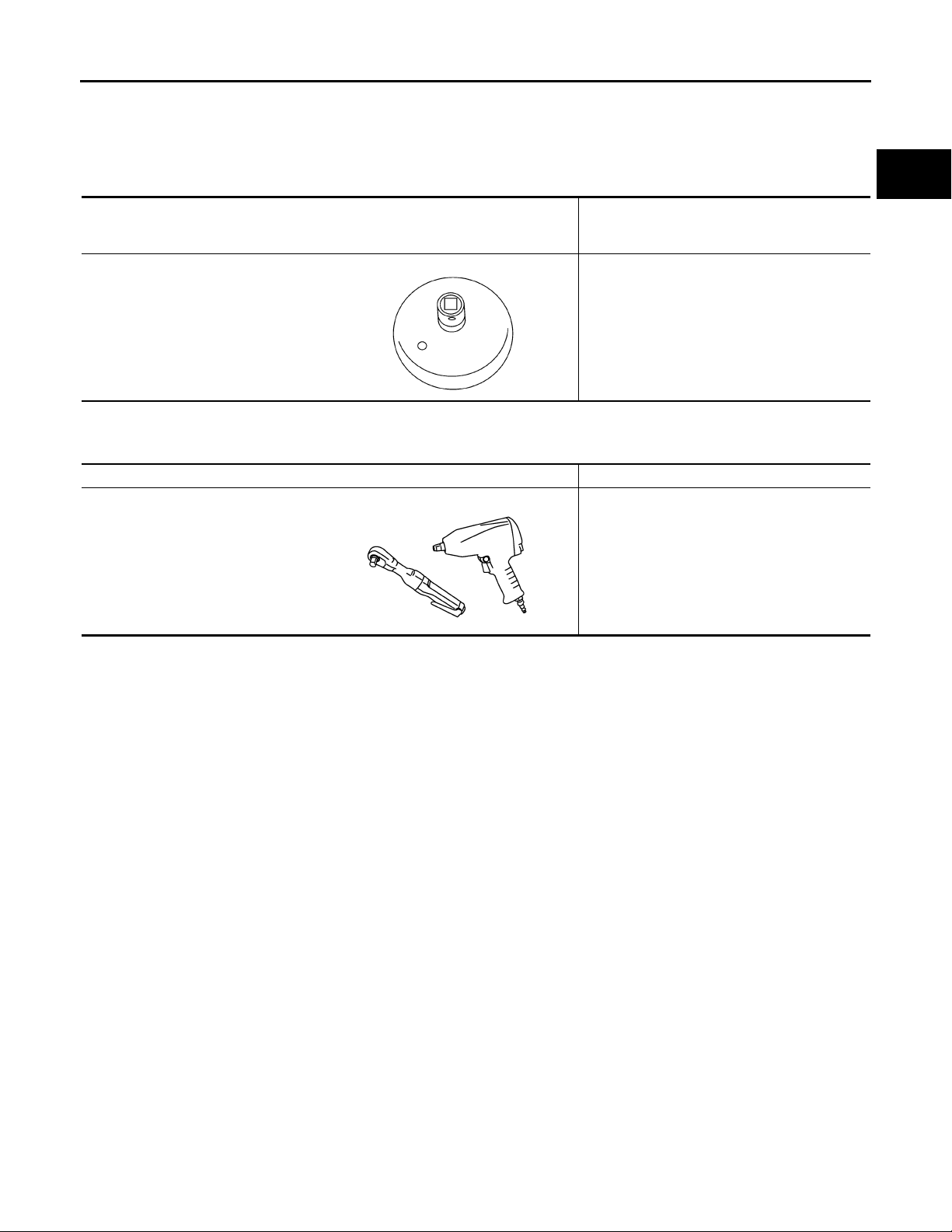
Special Service Tool INFOID:0000000001720988
The actual shapes of the Kent-Moore tools may differ from those of the special tools illustrated here.
Tool number
(Kent-Moore No.)
Tool name
KV991J0090
(J-46214)
Fuel tank lock ring tool
LBIA0353E
Commercial Service Tool INFOID:0000000001720989
Tool name Description
Power tools Loosening bolts and nuts
Description
Removing and installing fuel tank lock ring
A
FL
C
D
E
F
G
H
PBIC0190E
I
J
K
L
M
N
O
P
FL-3
Page 4
FUEL SYSTEM
Revision: July 2007 2008 Maxima
< SERVICE INFORMATION >
FUEL SYSTEM
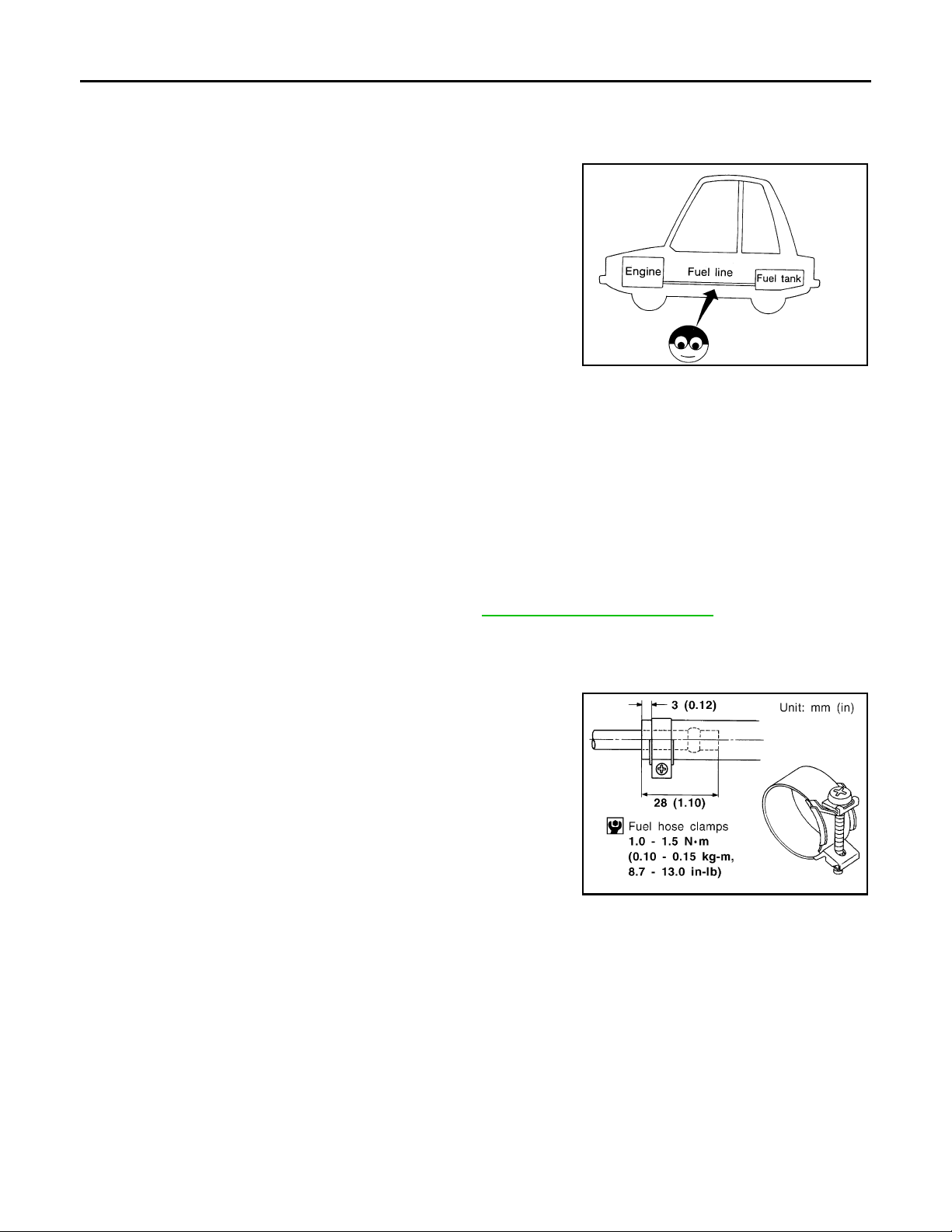
Checking Fuel Line INFOID:0000000001720990
Inspect fuel lines, filler cap and tank for improper attachment, leaks,
cracks, damage, loose connections, chafing or deterioration.
If necessary, repair or replace faulty parts as necessary.
SMA803A
General Precaution INFOID:0000000001720991
WARNING:
When replacing fuel line parts, be sure to observe the following.
• Put a “CAUTION: INFLAMMABLE” sign in the work area.
2
• Be sure to work in a well ventilated area and have a CO
• Do not smoke while working on the fuel system. Keep open flames and sparks away from the work
area.
CAUTION:
• Before removing fuel line parts, carry out the following procedures:
- Put drained fuel in an explosion-proof container and put the lid on securely. Keep the container in
safe area.
- Release fuel pressure from the fuel lines. Refer to EC-77, "
- Disconnect the battery ground cable.
• Always replace O-rings and clamps with new ones.
• Do not kink or twist tubes when they are being installed.
• Do not tighten hose clamps excessively to avoid damaging hoses.
Tighten high-pressure rubber hose clamp so that clamp end
is 3 mm (0.12 in) from hose end.
Tightening torque specifications are the same for all rubber
hose clamps.
Ensure that screw does not contact adjacent parts.
fire extinguisher.
Fuel Pressure Check".
MMA104A
FL-4
Page 5
FUEL SYSTEM
Revision: July 2007 2008 Maxima
< SERVICE INFORMATION >
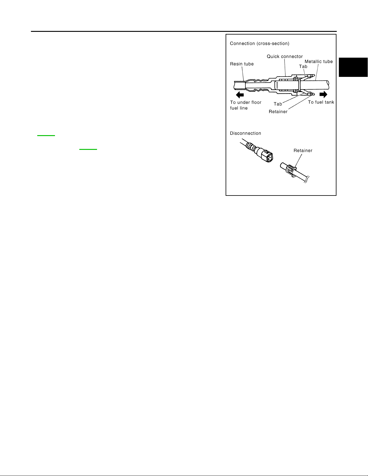
• After connecting the fuel tube quick connectors, make sure
the quick connectors are secure.
Ensure that the connector and resin tube do not contact any
adjacent parts.
- a) Apply fuel pressure to the fuel lines by turning the ignition
switch to ON (without starting the engine). Then check for fuel
leaks at the fuel tube connections.
- b) Start the engine and rev the engine, then check for fuel
leaks at the fuel tube connections.
• After installing tubes, run engine and check for fuel leaks at
connections.
• Use only a genuine NISSAN fuel filler cap as a replacement. If
an incorrect fuel filler cap is used, the MIL may come on.
• For servicing “Evaporative Emission System” parts, refer to
EC-30
.
• For servicing “On Board Refueling Vapor Recovery (ORVR)”
parts, refer to EC-36
.
A
FL
C
D
E
F
PBIC0199E
G
H
I
J
K
L
M
N
FL-5
O
P
Page 6

FUEL LEVEL SENSOR UNIT, FUEL FILTER AND FUEL PUMP ASSEMBLY
Revision: July 2007 2008 Maxima
< SERVICE INFORMATION >
FUEL LEVEL SENSOR UNIT, FUEL FILTER AND FUEL PUMP ASSEMBLY
Removal and Installation INFOID:0000000001720992
1. Lock ring 2. Fuel level sensor unit, fuel filter,
and fuel pump assembly
4. Fuel tank ⇐ Front
3. O-ring
REMOVAL
WARNING:
Read “General Precautions” before working on the fuel system.
Refer to FL-4, "
1. Unscrew the fuel filler cap to release the pressure inside the fuel tank.
2. Release the fuel pressure from the fuel lines. Refer to EC-77, "
3. Disconnect the battery negative terminal.
4. Remove the rear seat bottom. Refer to SE-89, "
5. Reposition the rear floor carpet out of the way to remove the fuel
pump inspection hole cover.
6. Turn the four retainers 90° in a clockwise direction and remove
the fuel pump inspection hole cover.
General Precaution".
Fuel Pressure Check".
Removal and Installation".
WAIA0107E
LBIA0337E
FL-6
Page 7

FUEL LEVEL SENSOR UNIT, FUEL FILTER AND FUEL PUMP ASSEMBLY
Revision: July 2007 2008 Maxima
< SERVICE INFORMATION >
7. Disconnect the fuel level sensor unit, fuel filter, and fuel pump
assembly electrical connector; EVAP hose; and fuel feed hose
from the fuel level sensor unit, fuel filter, and fuel pump assembly.
a. Disconnect the quick connectors as follows:
• Hold the sides of the connector, push in tubs and pull out the
tube.
• If the connector and the tube are stuck together, push and pull
several times until they start to move. Then disconnect them
by pulling.
CAUTION:
• The tube can be removed when the tabs are completely
depressed. Do not twist it more than necessary.
• Do not use any tools to remove the quick connector.
• Keep the resin tube away from heat. Be especially careful
when welding near the tube.
• Prevent acid liquid such as battery electrolyte, from getting on the resin tube.
• Do not bend or twist the tube during installation and removal.
• Only when the tube is replaced, remove the remaining retainer on the tube or fuel level sensor,
fuel filter, and fuel pump assembly.
• When the tube or fuel level sensor, fuel filter, and fuel pump assembly is replaced, also replace
the retainer with a new one (green colored retainer).
• To keep the connecting portion clean and to avoid dam-
age and foreign materials, cover them completely with
plastic bags or something similar.
A
FL
C
LBIA0338E
D
E
F
G
SFE562A
H
I
J
8. Remove the lock ring using a socket drive handle and Tool as
shown.
Tool number : KV991J0090 (J-46214)
K
L
PBIC0163E
M
N
O
P
WBIA0284E
FL-7
Page 8

FUEL LEVEL SENSOR UNIT, FUEL FILTER AND FUEL PUMP ASSEMBLY
Revision: July 2007 2008 Maxima
< SERVICE INFORMATION >
9. Remove the fuel level sensor, fuel filter, and fuel pump assembly.
CAUTION:
• Do not bend the float arm during removal.
INSPECTION AFTER REMOVAL
Make sure the fuel level sensor, fuel filter, and fuel pump is free from defects and foreign materials.
INSTALLATION
Installation is in the reverse order of removal.
• Install the fuel level sensor, fuel filter, and fuel pump assembly with
the fuel feed hose facing the front of the vehicle.
LBIA0339E
• Connect the quick connector as follows:
- Check the connection for damage or any foreign materials.
- Align the connector with the tube, then insert the connector straight
into the tube until a click is heard.
• After the tube is connected, make sure the connection is secure by
performing the following checks:
- Pull on the tube and the connector to make sure they are securely
connected.
LBIA0338E
SFE562A
FL-8
Page 9

FUEL LEVEL SENSOR UNIT, FUEL FILTER AND FUEL PUMP ASSEMBLY
Revision: July 2007 2008 Maxima
< SERVICE INFORMATION >
- Visually confirm that the two retainer tabs are connected to the
quick connector.
A
FL
C
D
E
F
PBIC0199E
INSPECTION AFTER INSTALLATION
Use the following procedure to check for fuel leaks.
1. Turn the ignition switch to ON (without st arting the engine) to check the connections for fuel leaks with the
electric fuel pump applying fuel pressure to the fuel piping.
2. Start the engine and let it idle to check that there are no fuel leaks at the fuel system tube and hose con-
nections.
Disassembly and Assembly INFOID:0000000001720993
Fuel Level Sender Unit
G
H
I
J
K
L
M
N
LBIA0458E
FL-9
O
P
Page 10

FUEL LEVEL SENSOR UNIT, FUEL FILTER AND FUEL PUMP ASSEMBLY
Revision: July 2007 2008 Maxima
< SERVICE INFORMATION >
1. Harness connectors 2. Fuel sensor 3. Tabs
4. Wire connector 5. Floater arm assembly
Disassembly
1. Disconnect the harness connectors (1) and the wire connector (4).
2. Remove the fuel sensor (2) from the pump assembly.
3. Depress the tabs (3) and remove the floater arm assembly (5).
Assembly
Assembly is the reverse order of disassembly.
FL-10
Page 11

< SERVICE INFORMATION >
Revision: July 2007 2008 Maxima
FUEL TANK
FUEL TANK
Removal and Installation INFOID:0000000001720994
A
FL
C
D
E
F
G
H
1. Lock ring 2. Fuel level sensor, fu el filter, and
fuel pump assembly
4. Fuel tank mounting straps 5. Fuel tank protector 6. Fuel tank
7. Fuel filler hose 8. Fuel filler tube 9. Grommet
10. Fuel filler cap
3. Ring seal
REMOVAL
WARNING:
Read “General Precautions” before working on the fuel system.
Refer to FL-4, "
1. Disconnect the battery negative terminal.
General Precaution".
I
J
K
L
M
WAIA0108E
N
O
P
FL-11
Page 12

FUEL TANK
Revision: July 2007 2008 Maxima
< SERVICE INFORMATION >
2. Check the fuel level with the vehicle on a level surface. If the fuel
gauge indicates more than the level as shown (7/8 full), drain
the fuel from the fuel tank until the fuel gauge indicates a level at
or below as shown (7/8 full).
• In case the fuel pump does not operate, use the following pro-
cedure.
a. Insert fuel tubing of less than 25mm (0.98in) diameter into the
fuel filler tube through the fuel filler opening to drain fuel from the
fuel filler tube.
b. Disconnect the fuel filler hose from the fuel filler tube.
c. Insert fuel tubing into the fuel tank through the fuel filler hose to
drain fuel from the fuel tank.
• As a guide, the fuel level reaches or is less than the level on the fuel gauge as shown, when approxi-
mately 10 (2 5/8 US gal, 2 1/4 Imp gal) of fuel is drained from a full fuel tank.
3. Open the fuel door and unscrew the fuel filler cap to release the pressure inside the fuel tank.
4. Release the fuel pressure from the fuel lines. Refer to EC-77, "
5. Disconnect the battery negative terminal.
6. Remove rear seat bottom. Refer to SE-89, "
Removal and Installation".
7. Reposition the rear floor carpet out of the way to remove the fuel
pump inspection hole cover.
8. Turn the four retainers 90° in a clockwise direction and remove
the fuel pump inspection hole cover.
Fuel Pressure Check".
SBIA0393E
9. Disconnect the fuel level sensor unit, fuel filter, and fuel pump
assembly electrical connector; and the fuel feed hose from the
fuel level sensor unit, fuel filter, and fuel pump assembly.
a. Disconnect the quick connectors as follows:
• Hold the sides of the connector, push in tubs and pull out the
tube.
• If the connector and the tube are stuck together, push and pull
several times until they start to move. Then disconnect them
by pulling.
CAUTION:
• The tube can be removed when the tabs are completely
depressed. Do not twist it more than necessary.
• Do not use any tools to remove the quick connector.
• Keep the resin tube away from heat. Be especially careful
when welding near the tube.
• Prevent acid liquid such as battery electrolyte, from getting on the resin tube.
• Do not bend or twist the tube during installation and removal.
• Only when the tube is replaced, remove the remaining retainer on the tube or fuel level sensor,
fuel filter, and fuel pump assembly.
LBIA0337E
LBIA0338E
SFE562A
FL-12
Page 13

FUEL TANK
Revision: July 2007 2008 Maxima
< SERVICE INFORMATION >
• When the tube or fuel level sensor, fuel filter, and fuel pump assembly is replaced, also replace
the retainer with a new one (green colored retainer).
• To keep the connecting portion clean and to avoid damage and foreign materials, cover them completely with
plastic bags or something similar.
A
FL
C
D
PBIC0163E
10. Remove the center exhaust tube, with mufflers. Refer to EX-4, "
Removal and Installation".
11. Disconnect the three parking brake cable mounting brackets on each cable and position the cables out of
the way. Refer to PB-4, "
Component".
12. Remove the fuel tank protector.
13. Disconnect the fuel filler hose, recirculation hose and EVAP canister hose at the fuel tank as shown.
E
F
G
H
I
J
K
L
LBIA0341E
14. Disconnect the fuel tank mounting straps while supporting the fuel tank.
15. Remove the fuel tank.
16. If replacing the fuel tank, remove the fuel level sensor, fuel filter and fuel pump assembly to transfer to the
new fuel tank.
INSTALLATION
Installation is in the reverse order of removal.
• Before tightening the fuel tank mounting straps, temporarily install the filler hose, recirculation hose, and sig-
nal hose. Tighten all fasteners to specification.
FL-13
M
N
O
P
Page 14

FUEL TANK
Revision: July 2007 2008 Maxima
< SERVICE INFORMATION >
• Connect the quick connector as follows:
- Check the connection for damage or any foreign materials.
- Align the connector with the tube, then insert the connector straight
into the tube until a click is heard.
• After the tube is connected, make sure the connection is secure by
performing the following checks:
- Pull on the tube and the connector to make sure they are securely
connected.
- Visually confirm that the two retainer tabs are connected to the
quick connector.
SFE562A
PBIC0199E
INSPECTION AFTER INSTALLATION
Use the following procedure to check for fuel leaks.
1. Turn the ignition switch to ON (without st arting the engine) to check the connecti ons for fuel leaks wi th the
electric fuel pump applying fuel pressure to the fuel piping.
2. Start the engine and let it idle to check that there are no fuel leaks at the fuel system tube and hose con-
nections.
FL-14
Page 15

SERVICE DATA AND SPECIFICATIONS (SDS)
Revision: July 2007 2008 Maxima
< SERVICE INFORMATION >
SERVICE DATA AND SPECIFICATIONS (SDS)
Standard and Limit INFOID:0000000001720995
Fuel Tank
unit: (US gal, Imp gal)
Fuel tank capacity 75.6 (20, 16 5/8)
A
FL
C
D
E
F
G
H
K
M
N
O
P
I
J
L
FL-15
 Loading...