

Page 1

C TRANSMISSION/TRANSAXLE
A
B
SECTION
CONTENTS
INDEX FOR DTC ........................................................ 5
Alphabetical Index .................................................... 5
DTC No. Index ......................................................... 6
PRECAUTIONS .......................................................... 7
Precautions for Supplementa l Restraint System
(SRS) “AIR BAG” and “SEAT BELT PRE-TEN-
SIONER” .................................................................. 7
Precautions for On Board Diagnostic (OBD) System
of A/T and Engine .................................................... 7
Precautions for A/T Assembly or TCM Replacement ..... 8
Precautions .............................................................. 9
Service Notice or Precautions .................................11
Wiring Diagrams and Trouble Diagnosis .................11
PREPARATION ..................................... .................... 12
Special Service Tools ............................................. 12
Commercial Service Tools ...................................... 14
A/T FLUID ................................................................. 15
Changing A/T Fluid ..................... ....... ...... ....... ....... 15
Checking A/T Fluid ................................................. 15
A/T CONTROL SYSTEM .......................................... 16
Cross-Sectional View ............................................. 16
Shift Mechanism ..................................................... 17
TCM Function ........... ...... ....... ...... ....... ...... ....... ....... 34
Input/Output Signal of TCM .................................... 35
CAN Communication .............................................. 35
Line Pressure Control ........... ...... ....... ...... ....... ....... 36
Shift Control ........................................................... 36
Lock-Up Control ..................................................... 38
ON BOARD DIAGNOSTIC (OBD) SYSTEM ............ 40
Introduction ............................................................ 40
OBD-II Function for A/T System ............................. 40
One or Two Trip Detection Logic of OBD-II ............ 40
OBD-II Diagnostic Trouble Code (DTC) ................. 40
Malfunction Indicator Lamp (MIL) ........................... 43
TROUBLE DIAGNOSIS ............................................ 44
DTC Inspection Priority Chart ................................ 44
Fail-Safe ................................ ................................. 44
How T o Perform Trouble Diagnosis For Quick and
Accurate Repair ..................................................... 47
A/T Electrical Parts Location .................................. 52
AUTOMATIC TRANSAXLE
Circuit Diagram .......................................................53
Inspections Before Trouble Diagnosis .................... 54
Check Before Engine is Started .............................. 58
Check at Idle ...........................................................58
Cruise Test - Part 1 .................................................60
Cruise Test - Part 2 .................................................61
Cruise Test - Part 3 .................................................62
Shift Schedule ........................................................63
Symptom Chart .......................................................64
TCM Input/Output Signal Reference Values ........... 71
CONSULT-II Function (TCM) .................................. 74
Diagnostic Procedure Without CONSULT-II ........... 80
DTC U1000 CAN COMMUNICATION LINE .............. 83
Description ................... ...... ....... ...... ........................ 83
On Board Diagnosis Logic ......................................83
Possible Cause .......................................................83
DTC Confirmation Procedure ................................. 83
Wiring Diagram — AT — CAN ................................84
Diagnostic Procedure .............................................85
DTC P0500 VEHICLE SPEED SENSOR MTR ......... 86
Description ................... ...... ....... ...... ........................ 86
On Board Diagnosis Logic ......................................86
Possible Cause .......................................................86
DTC Confirmation Procedure ................................. 86
Diagnostic Procedure .............................................87
DTC P0613 TCM PROCESSOR .............. .................88
Description ................... ...... ....... ...... ........................ 88
On Board Diagnosis Logic ......................................88
Possible Cause .......................................................88
DTC Confirmation Procedure ................................. 88
Diagnostic Procedure .............................................89
DTC P0705 P ARK/NEUTRAL POSITION SWITCH ...90
Description ................... ...... ....... ...... ........................ 90
On Board Diagnosis Logic ......................................90
Possible Cause .......................................................90
DTC Confirmation Procedure ................................. 90
Wiring Diagram — AT — PNP/SW .........................91
Diagnostic Procedure .............................................92
Component Inspection ............................................94
DTC P0710 A/T FLUID TEMPERATURE SENSOR
AT
D
E
F
G
H
I
J
K
L
M
Revision: July 2005 2005 Maxima
AT-1
Page 2

CIRCUIT .................................................................... 95
Description ................ .......................... .................... 95
On Board Diagnosis Logic ...................................... 95
Possible Cause .......................................................95
DTC Confirmation Procedure ................... ....... .......95
Wiring Diagram — AT — FTS .................................96
Diagnostic Procedure ............................................. 97
Component Inspection ............................................99
DTC P0711 FLUID TEMPERA TURE SENSOR PER-
FORMANCE ............................. ...............................100
Description ................ .......................... ..................100
On Board Diagnosis Logic ....................................100
Possible Cause .....................................................100
DTC Confirmation Procedure ................... ....... .....100
Wiring Diagram — AT — FTSP ............................101
Diagnostic Procedure ...........................................102
Component Inspection ..........................................104
DTC P0717 TURBINE REVOLUTION SENSOR CIR-
CUIT ........................................................................105
Description ................ .......................... ..................105
On Board Diagnosis Logic ....................................105
Possible Cause .....................................................105
DTC Confirmation Procedure ................... ....... .....105
Wiring Diagram — AT — TRSC ............................106
Diagnostic Procedure ...........................................107
Component Inspection ..........................................108
DTC P0722 VEHICLE SPEED SENSOR A/T (REV-
OLUTION SENSOR) CIRCUIT ................................109
Description ................ .......................... ..................109
On Board Diagnosis Logic ....................................109
Possible Cause .....................................................109
DTC Confirmation Procedure ................... ....... .....109
Wiring Diagram — AT — VSSATC .......................110
Diagnostic Procedure ............................................111
Component Inspection ..........................................112
DTC P0726 ENGINE SPEED INPUT CIRCUIT PER-
FORMANCE ............................. ...............................113
Description ................ .......................... ..................113
On Board Diagnosis Logic ....................................113
Possible Cause .....................................................113
DTC Confirmation Procedure ................... ....... .....113
Diagnostic Procedure ...........................................113
DTC P0731 A/T 1ST GEAR FUNCTION .................115
Description ................ .......................... ..................115
On Board Diagnosis Logic ....................................115
Possible Cause .....................................................115
DTC Confirmation Procedure ................... ....... .....115
Wiring Diagram — AT — 1STSIG .........................116
Diagnostic Procedure ...........................................117
DTC P0732 A/T 2ND GEAR FUNCTION ................118
Description ................ .......................... ..................118
On Board Diagnosis Logic ....................................118
Possible Cause .....................................................118
DTC Confirmation Procedure ................... ....... .....118
Wiring Diagram — AT — 2NDSIG ........................120
Diagnostic Procedure ...........................................122
DTC P0733 A/T 3RD GEAR FUNCTION ................124
Description ................ .......................... ..................124
On Board Diagnosis Logic ....................................124
Possible Cause .....................................................124
DTC Confirmation Procedure ................................124
Wiring Diagram — AT — 3RDSIG ........................126
Diagnostic Procedure ............................................128
DTC P0734 A/T 4TH GEAR FUNCTION .................130
Description ............................................................130
On Board Diagnosis Logic ....................................130
Possible Cause .....................................................130
DTC Confirmation Procedure ................................130
Wiring Diagram — AT — 4THSIG .........................132
Diagnostic Procedure ............................................133
DTC P0735 A/T 5TH GEAR FUNCTION .................135
Description ............................................................135
On Board Diagnosis Logic ....................................135
Possible Cause .....................................................135
DTC Confirmation Procedure ................................135
Wiring Diagram — AT — 5THSIG .........................137
Diagnostic Procedure ............................................139
DTC P0744 A/T TCC S/V FUNCTION (LOCK-UP) .141
Description ............................................................141
On Board Diagnosis Logic ....................................141
Possible Cause .....................................................141
DTC Confirmation Procedure ................................141
Wiring Diagram — AT — TCCSIG ........................142
Diagnostic Procedure ............................................143
DTC P0745 PRESSURE CONTROL SOLENOID
VALVE A (LINE PRESSURE) ..................................144
Description ............................................................144
On Board Diagnosis Logic ....................................144
Possible Cause .....................................................144
DTC Confirmation Procedure ................................144
Wiring Diagram — AT — PC/A .............................145
Diagnostic Procedure ............................................146
Component Inspection ..........................................148
DTC P0750 SHIFT SOLENOID VALVE A ...............149
Description ............................................................149
On Board Diagnosis Logic ....................................149
Possible Cause .....................................................149
DTC Confirmation Procedure ................................149
Wiring Diagram — AT — SSV/A ...........................150
Diagnostic Procedure ............................................151
Component Inspection ..........................................153
DTC P0755 SHIFT SOLENOID VALVE B ...............154
Description ............................................................154
On Board Diagnosis Logic ....................................154
Possible Cause .....................................................154
DTC Confirmation Procedure ................................154
Wiring Diagram — AT — SSV/B ...........................155
Diagnostic Procedure ............................................156
Component Inspection ..........................................158
DTC P0760 SHIFT SOLENOID VALVE C ...............159
Description ............................................................159
On Board Diagnosis Logic ....................................159
Possible Cause .....................................................159
DTC Confirmation Procedure ................................159
Wiring Diagram — AT — SSV/C ...........................160
Diagnostic Procedure ............................................161
Component Inspection ..........................................163
DTC P0762 SHIFT SOLENOID VAL VE C STUCK ON .164
Revision: July 2005 2005 Maxima
AT-2
Page 3

Description ........................................................... 164
On Board Diagnosis Logic ................................... 164
Possible Cause .................................................... 164
DTC Confirmation Procedure ............................... 164
Wiring Diagram — AT — SSV/CS ........................ 165
Diagnostic Procedure ........................................... 166
Component Inspection ......................................... 168
DTC P0765 SHIFT SOLENOID VALVE D .............. 169
Description ........................................................... 169
On Board Diagnosis Logic ................................... 169
Possible Cause .................................................... 169
DTC Confirmation Procedure ............................... 169
Wiring Diagram — AT — SSV/D .......................... 170
Diagnostic Procedure ........................................... 171
Component Inspection ......................................... 173
DTC P0770 SHIFT SOLENOID VALVE E .............. 174
Description ........................................................... 174
On Board Diagnosis Logic ................................... 174
Possible Cause .................................................... 174
DTC Confirmation Procedure ............................... 174
Wiring Diagram — AT — SSV/E .......................... 175
Diagnostic Procedure ........................................... 176
Component Inspection ......................................... 178
DTC P0775 PRESSURE CONTROL SOLENOID
VALVE B (SHIFT PRESSURE) ............................... 179
Description ........................................................... 179
On Board Diagnosis Logic ................................... 179
Possible Cause .................................................... 179
DTC Confirmation Procedure ............................... 179
Wiring Diagram — AT — PC/B ............................. 180
Diagnostic Procedure ........................................... 181
Component Inspection ......................................... 183
DTC P0780 SHIFT .................................................. 184
Description ........................................................... 184
On Board Diagnosis Logic ................................... 184
Possible Cause .................................................... 184
DTC Confirmation Procedure ............................... 184
Wiring Diagram — AT — SFTFNC ....................... 185
Diagnostic Procedure ........................................... 187
DTC P0795 PRESSURE CONTROL SOLENOID
VALVE C (TCC AND SHIFT PRESSURE) ............. 188
Description ........................................................... 188
On Board Diagnosis Logic ................................... 188
Possible Cause .................................................... 188
DTC Confirmation Procedure ............................... 188
Wiring Diagram — AT — PC/C ............................ 189
Diagnostic Procedure ........................................... 190
Component Inspection ......................................... 192
DTC P0797 PRESSURE CONTROL SOLENOID
VALVE C STUCK ON ............................................. 193
Description ........................................................... 193
On Board Diagnosis Logic ................................... 193
Possible Cause .................................................... 193
DTC Confirmation Procedure ............................... 193
Wiring Diagram — AT — PC/CS .......................... 194
Diagnostic Procedure ........................................... 195
Component Inspection ......................................... 197
DTC P0826 MANUAL MODE SWITCH CIRCUIT .. 198
Description ........................................................... 198
CONSULT-II Reference Value in Data Monitor Mode
.198
On Board Diagnosis Logic ....................................198
Possible Cause .....................................................198
DTC Confirmation Procedure ...............................198
Wiring Diagram — AT — MMSW .........................199
Diagnostic Procedure ...........................................201
Component Inspection ..........................................203
Position Indicator ................................... ...... ....... ..203
DTC P0882 TCM POWER INPUT SIGNAL ............204
Description ................... ...... ....... ...... ......................204
On Board Diagnosis Logic ....................................204
Possible Cause .....................................................204
DTC Confirmation Procedure ...............................204
Wiring Diagram — AT — PWR/IN ........................205
Diagnostic Procedure ...........................................207
Component Inspection ..........................................208
DTC P1726 ELECTRIC THROTTLE CONTROL
SYSTEM ......................... ....................................... ..209
Description ................... ...... ....... ...... ......................209
TROUBLE DIAGNOSIS FOR SYMPTOMS ............210
A/T CHECK Indicator Lamp does not come on ....210
Engine Cannot Be Started In “P” or “N” Position ..212
In “P” Position, Vehicle Moves When Pushed ......212
In “N” Position, Vehicle Moves ..............................213
Large Shock (“N” to “D” Position) .........................214
Vehicle Does Not Creep Backward In “R” Position .215
Vehicle Does Not Creep Forward In “D” Position . 216
Vehicle Cannot Be Started From D
A/T Does Not Shift: D
A/T Does Not Shift: D
A/T Does Not Shift: D
A/T Does Not Shift: D
1 → D2 ....................... .........217
2 → D3 ....................... .........218
3 → D4 ....................... .........219
4 → D5 ....................... .........220
1 .....................217
A/T Does Not Perform Lock-up ............................221
A/T Does Not Hold Lock-up Condition ..................222
Lock-up Is Not Released ......................................223
Cannot Be Changed to Manual Mode ..................224
A/T Does Not Shift: 5th gear → 4th gear ..............225
A/T Does Not Shift: 4th gear → 3rd gear ..............226
A/T Does Not Shift: 3rd gear → 2nd gear .............226
A/T Does Not Shift: 2nd gear → 1st gear .............227
Vehicle Does Not Decelerate By Engine Brake ....228
TCM Self-diagnosis Does Not Activate ................229
SHIFT CONTROL SYSTEM ....................................231
Control Device ......................................................231
Control Cable ........................................................232
A/T SHIFT LOCK SYSTEM ....................................233
Description ................... ...... ....... ...... ......................233
Shift Lock System Electrical Parts Location .........233
Wiring Diagram — AT — SHIFT ...........................234
Shift Lock Control Unit Reference Values ............235
Component Inspection ..........................................236
ON-VEHICLE SERVICE ..........................................238
Revolution Sensor Replacement ..........................238
Turbine Revolution Sensor Replacement .............238
Park/Neutral Position (PNP) Switch Adjustment ..238
ATF Cooler ...........................................................239
ATF Cooler Valve ..................................................239
Control Cable Adjustment .....................................240
A
B
AT
D
E
F
G
H
I
J
K
L
M
Revision: July 2005 2005 Maxima
AT-3
Page 4

Side cover .............................................................241
Control Valve Assembly ........................................241
Terminal cord assembly ........................................241
TRANSAXLE ASSEMBLY .................... ...... ....... .....243
Removal and Installation ......................................243
INSPECTION AFTER REMOVAL .........................243
OVERHAUL ....................... ....... ...... ....... ...... ....... .....245
Components .........................................................245
Locations o f Needle Bea rings, Be aring Races and
Thrust Washers ....................................................251
DISASSEMBLY .......................................................252
Disassembly .........................................................252
REPAIR FOR COMPONENT PARTS ......................272
Oil Pump, 2nd Coast Brake & 2nd Brake .............272
One-Way Clutch Outer Race Sub Assembly & 2nd
Coast Brake Hub & One-Way Clutch No.1 ...........278
Transaxle Case Cover & B5 Brake .......................280
Differential Gear Assembly ...................................285
ASSEMBLY .............................................................288
Assembly (1) ................................... ....... ...... ....... ..288
Adjustment ............................................................295
Assembly (2) ................................... ....... ...... ....... ..296
SERVICE DATA AND SPECIFICATIONS (SDS) ....312
General Specifications ..........................................312
Shift Schedule .......................................................312
Stall Speed ............................................................313
Line Pressure ........................................................313
Time Lag .. ....... ...... ....... ....................................... ..313
Shift Solenoid Valves ............................................313
Solenoid Valves ....................................................314
Clutch and Brakes ........ ...... ....... ...... ......................314
Final Drive .............................................................315
A/T Fluid Temperature Sensor ..............................316
Turbine Revolution Sensor ....................................316
Revolution Sensor .................................................316
Revision: July 2005 2005 Maxima
AT-4
Page 5
INDEX FOR DTC
INDEX FOR DTC PFP:00024
Alphabetical Index ECS00A0H
NOTE:
If DTC U1000 is displayed with other DTCs, first perform the trouble diagnosis for DTC U1000. Refer to
.
AT-83
DTC
Items
(CONSULT-II screen terms)
A/T 1ST GR FNCTN P0731 P0731 AT-115
A/T 2ND GR FNCTN P0732 P0732 AT-118
A/T 3RD GR FNCTN P0733 P0733 AT-124
A/T 4TH GR FNCTN P0734 P0734 AT-130
A/T 5TH GR FNCTN P0735 P0735 AT-135
A/T TCC S/V FNCTN P0744 P0744 AT-141
ATF TEMP SEN/CIRC P0710 P0710 AT-95
CAN COMM CIRCUIT U1000 U1000 AT-83
ELEC TH CONTROL — P1726 AT-209
ENG SPD INP PERFOR — P0726 AT-113
FLUID TEMP SEN P0711 P0711 AT-100
MANUAL MODE SWITCH — P0826 AT-198
PC SOL A(L/PRESS) P0745 P0745 AT-144
PC SOL B(SFT/PRS) P0775 P0775 AT-179
PC SOL C(TCC&SFT) P0795 P0795 AT-188
PC SOL C STC ON P0797 P0797 AT-193
PNP SW/CIRC P0705 P0705 AT-90
SHIFT P0780 P0780 AT-184
SHIFT SOL A P0750 P0750 AT-149
SHIFT SOL B P0755 P0755 AT-154
SHIFT SOL C P0760 P0760 AT-159
SHIFT SOL D P0765 P0765 AT-169
SHIFT SOL E P0770 P0770 AT-174
SFT SOL C STUCK ON P0762 P0762 AT-164
TCM POWER INPT SIG P0882 P0882 AT-204
TCM PROCESSOR — P0613 AT-88
TURBINE SENSOR P0717 P0717 AT-105
VEH SPD SE/CIR-MTR — P0500 AT-86
VHCL SPEED SEN-A/T P0722 P0722 AT-109
*1: These numbers are prescribed by SAE J2012.
OBD-II Except OBD-II
CONSULT-II
*1
GST
CONSULT -II
only “TRANSMIS-
SION”
Reference page
A
B
AT
D
E
F
G
H
I
J
K
L
M
Revision: July 2005 2005 Maxima
AT-5
Page 6

INDEX FOR DTC
DTC No. Index ECS00A0I
NOTE:
If DTC U1000 is displayed with other DTCs, first perform the trouble diagnosis for DTC U1000. Refer to
.
AT-83
DTC
OBD-II Except OBD-II
CONSULT-II
*1
GST
— P0500 VEH SPD SE/CIR-MTR AT-86
— P0613 TCM PROCESSOR AT-88
P0705 P0705 PNP SW/CIRC AT-90
P0710 P0710 ATF TEMP SEN/CIRC AT-95
P0711 P0711 FLUID TEMP SEN AT-100
P0717 P0717 TURBINE SENSOR AT-105
P0722 P0722 VHCL SPEED SEN-A/T AT-109
— P0726 ENG SPD INP PERFOR AT-113
P0731 P0731 A/T 1ST GR FNCTN AT-115
P0732 P0732 A/T 2ND GR FNCTN AT-118
P0733 P0733 A/T 3RD GR FNCTN AT-124
P0734 P0734 A/T 4TH GR FNCTN AT-130
P0735 P0735 A/T 5TH GR FNCTN AT-135
P0744 P0744 A/T TCC S/V FNCTN AT-141
P0745 P0745 PC SOL A(L/PRESS) AT-144
P0750 P0750 SHIFT SOL A AT-149
P0755 P0755 SHIFT SOL B AT-154
P0760 P0760 SHIFT SOL C AT-159
P0762 P0762 SFT SOL C STUCK ON AT-164
P0765 P0765 SHIFT SOL D AT-169
P0770 P0770 SHIFT SOL E AT-174
P0775 P0775 PC SOL B(SFT/PRS) AT-179
P0780 P0780 SHIFT AT-184
P0795 P0795 PC SOL C(TCC&SFT) AT-188
P0797 P0797 PC SOL C STC ON AT-193
— P0826 MANUAL MODE SWITCH AT-198
P0882 P0882 TCM POWER INPT SIG AT-204
— P1726 ELEC TH CONTROL AT-209
U1000 U1000 CAN COMM CIRCUIT AT-83
*1: These numbers are prescribed by SAE J2012.
CONSULT -II
only “TRANSMIS-
SION”
(CONSULT-II screen terms )
Items
Reference page
Revision: July 2005 2005 Maxima
AT-6
Page 7

PRECAUTIONS
PRECAUTIONS PFP:00001
Precautions for Supplemental Restraint System (SRS) “ AIR BAG” and “SEAT BELT PRE-TENSIONER”
ECS00A0J
A
The Supplemental Rest raint System such as “AIR BAG” and “SEAT BELT PRE-TENSIO NER”, used along
with a front seat belt, helps to reduce the risk or severity of injury to the driver and front passenger for certain
types of collision. This system includ es seat belt switch inputs and dual stage front air bag modules. The SRS
system uses the seat belt switches to determine the front air bag deployment, and may only deploy one front
air bag, depending on the severity of a collision and whether the front occupants are belted or unbelted.
Information necessary to service the system safely is included in the SRS and SB section of this Service Manual.
WARNING:
● To avoid ren dering the SRS ino perative, w hich could inc rease the ris k of personal injury or death
in the event of a collision which would result in air bag inflation, all maintenance must be performed by an authorized NISSAN/INFINITI dealer.
● Improper maintenance, inc luding incorrect removal and installation of the SRS, can lead to per-
sonal injury ca use d by unintentional ac tiv atio n o f the system. For remo va l of Spiral Cable and Air
Bag Module, see the SRS section.
● Do not use electrical test equ ipment o n any circu it related to the SRS unless in structed to in this
Service Manual. SRS wiring harnesses can be identified by yellow and/or orange harnesses or
harness connectors.
Precautions for On Board Diagnostic (OBD) System of A/T and Engine ECS00A0K
The ECM has an on boa rd diagnos tic system. It wil l light up the m alfunction indicator la mp (MIL) to warn th e
driver of a malfunction causing emission deterioration.
CAUTION:
● Be sure to turn the ignition switch “OFF” and disconnect the negative battery cable before any
repair or inspection work. The open/short circuit of related switches, sensors, solenoid valves,
etc. will cause the MIL to light up.
● Be sure to connect and lock the connectors securely after work. A loose (unlocked) connector will
cause the MIL to light up due to an open circuit. (Be sure the connector is free from water, grease,
dirt, bent terminals, etc.)
● Be sure to route and secure the harnesses properly after work. Interference of the harness with a
bracket, etc. may cause the MIL to light up due to a short circuit.
● Be sure to connect rubber tubes properly after work. A misconnected or disconnected rubber tube
may cause the MIL to light up due to a malfunction of the EGR system or fuel injection system, etc.
● Be sure to eras e the u nnecess ary mal function i nformatio n (repairs compl eted) from the TC M and
ECM before returning the vehicle to the custom er.
B
AT
D
E
F
G
H
I
J
K
L
Revision: July 2005 2005 Maxima
AT-7
M
Page 8

PRECAUTIONS
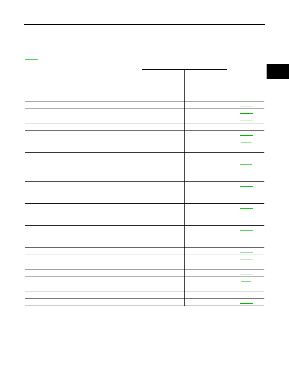
Precautions for A/T Assembly or TCM Replacement ECS00A0L
● When replacing A/T assembly or TCM, refer to the pattern table below and initialize TCM if necessary.
TCM INITIALIZATION PATTERNS
TCM A/T assembly Erasing EEPROM in TCM Remarks
Replaced with
new one
Not replaced
Replaced with
old one
NOTE:
“Old one” is the TCM or A/T assembly that has been used on other vehicles.
METHOD FOR TCM INITIALIZATION
1. Perform “CONSULT-II SETTING PROCEDURE”. Refer to AT-75, "CONSULT-II SETTING PROCEDURE"
.
2. Set the vehicle following the items listed below.
● Ignition switch “ON”.
● Selector lever “P” or “N” position.
● Engine not running.
● Vehicle speed is 0 km/h (0 MPH).
● Ignition voltage is more than 10.5V.
● Malfunction was not detected.
3. Touch “WORK SUPPORT”.
4. Touch “INITIALIZATION”.
5. Initialize TCM following the direction in display.
Not replaced
Replaced with
new or old one
Replaced with
new or old one
Not replaced
Replaced with
new or old one
Not required
Required
Not required because the EEPROM in TCM is in the default
state.
Required because data cannot be conformed to previ ous
data written in the EEPROM in TCM.
Revision: July 2005 2005 Maxima
AT-8
Page 9
PRECAUTIONS
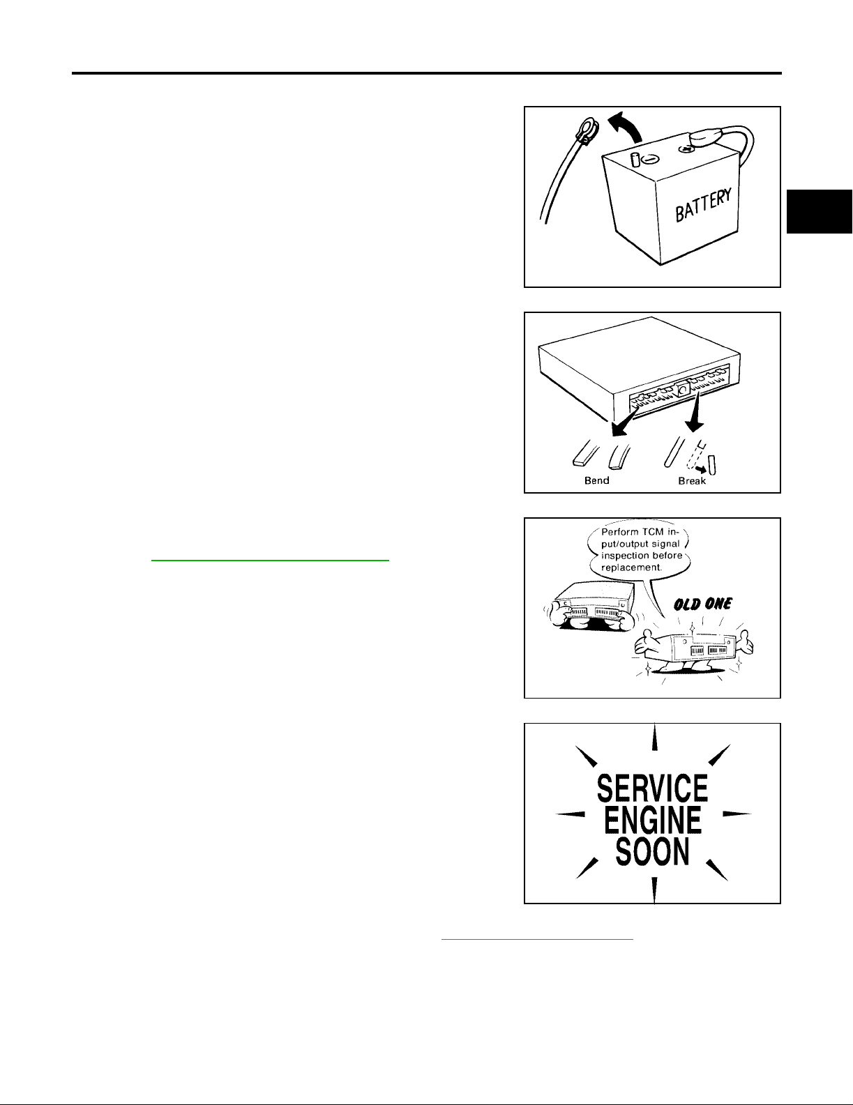
Precautions ECS00A0M
● Before connecting or dis connecting the TCM harness con-
nector, turn ignition switch “OFF” and d isconnect ne gative
battery cable. Because battery voltage is applied to TCM
even if ignition switch is turned “OFF”.
A
B
AT
● When connecting or disconnecting pin connectors i nto or
from TCM, take care not to dama ge pin terminals (bend or
break).
Make sure that there are not any ben ds or breaks on TCM
pin terminal, when connecting pin connectors.
● Before replacing TCM, perform TCM input/output signal
inspection and make sure wheth er TCM functions properly
or not. AT-72, "
TCM INSPECTION TABLE".
SEF289H
SEF291H
D
E
F
G
H
I
J
K
MEF040DA
● After performing each TROUBLE DIAGNOSIS, perform
“DTC (Diagnostic Trouble Code) CONFIRMATION PROCEDURE”.
The DTC should not be displ ayed in the “DTC CONFIRMATION PROCEDURE” if the repair is completed.
SEF217U
● Always use the specified brand of A/T fluid. Refer to MA-9, "Fluids and Lubricants" .
● Use paper ra gs not cloth rags during work.
● After replacing the A/T fluid, dispose of the waste oil using the method s prescribed by law, ordinance, etc.
● Before proceed ing with dis assemb ly, thoroughly clean the outsid e of the tran saxle. It is important t o pre-
vent the internal parts from becoming contaminated by dirt or other foreign matter.
● Disassembly should be done in a clean work area.
Revision: July 2005 2005 Maxima
AT-9
L
M
Page 10

PRECAUTIONS
● Use lint-free cloth or towels for wiping parts clean. Common shop rags can leave fibers that could interfere
with the operation of the transax le .
● Place disassembled parts in order for easier and pro per assembly.
● All parts should be carefully cleaned with a general purpose, non-flammable solvent before inspection or
reassembly.
● Gaskets, seals and O-rings should be replaced any time the transaxle is disassembled.
● It is very important to perform functional tests whenever they are indicated.
● The valve bo dy co ntains precision p a rts and requires extre me ca re w h en p ar t s ar e r em ov ed and s er v ic ed .
Place disassembled valve body parts in order for easier and proper assembly. Care will also prevent
springs and small parts from be coming scattered or lost .
● Properly installed valves, sle ev e s, plugs, etc. will slide along bores in valve body unde r thei r own we ig ht.
● Before assembly, apply a coat of recommended ATF to all parts. Apply petroleum jelly to protect O-rings
and seals, or hold bearings and washers in place during assembly. Do not use grease.
● Extreme care should be taken to avoid damage to O-rings, seals and gaskets when assembling.
● After over haul, refill the transaxle with new ATF.
● When the A/T drain plug is remove d, only some of t he fluid is drai ned. O ld A/T flu id wil l remain i n torque
converter and ATF cooling system.
Always follow the procedures under “Changing A/T Fluid” in the AT section when changing A/T fluid. Refer
to AT-15, "
Changing A/T Fluid" , AT-15, "Checking A/T Fluid" .
Revision: July 2005 2005 Maxima
AT-10
Page 11

PRECAUTIONS
Service Notice or Precautions ECS00A0N
ATF COOLER SERVICE
If A/T fluid contains frictional material (clutches, bands, etc.), or if an A/T is repaired, overhauled, or replaced,
inspect and cl ean the A/T oil c ooler mounted in the radiator or replace the radi ator. Flush cooler lines us ing
cleaning solvent and compressed air after repair. Check Service Bulletins for latest A/T oil cooler cleaning procedure. For radiator replacement, refer to CO-12, "
RADIATOR" .
OBD-II SELF-DIAGNOSIS
● A/T self-diagnosis is performed by the TCM in combination with the ECM. The results can be read through
the blinking pattern of the A/T CHECK indicator or the malfunction indicator lamp (MIL). Refer to the table
on AT-75, "
● The self-diagnostic results indicated by the MIL are automatically stored in both the ECM and TCM mem-
ories.
Always perform the procedure on AT-41, "
unnecessary blinking of the MIL.
● For details of OBD-II, refer to EC-49, "ON BOARD DIAGNOSTIC (OBD) SYSTEM" .
● Certain systems and com ponents, especially those related to OBD , may use the n ew style slide-
locking type harness connector. For description and how to disconnect, refer to PG-62, "
NESS CONNECTOR" .
SELF-DIAG RESULT MODE" for the indicator used to display each self-diagnostic result.
HOW TO ERASE DTC" to complete the repair a nd avoid
HAR-
Wiring Diagrams and Trouble Diagnosis ECS00A0O
When you read wiring diagrams, refer to the following:
● GI-13, "How to Read Wiring Diagrams".
● PG-4, "POWER SUPPLY ROUTING CIRCUIT" for power distribution circuit.
When you perform trouble diagnosis, refer to the following:
● GI-9, "How to Follow Trouble Diagnoses".
● GI-25, "How to Perform Efficient Diagnosis for an Electrical Incident".
A
B
AT
D
E
F
G
H
I
K
M
J
L
Revision: July 2005 2005 Maxima
AT-11
Page 12
PREPARATION
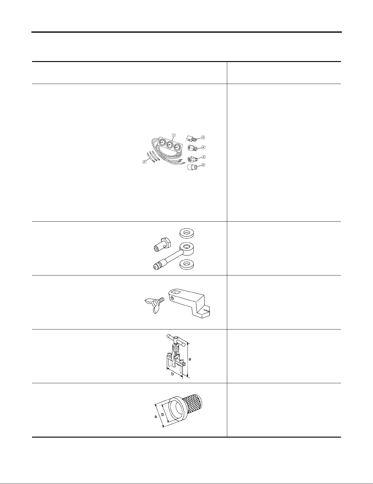
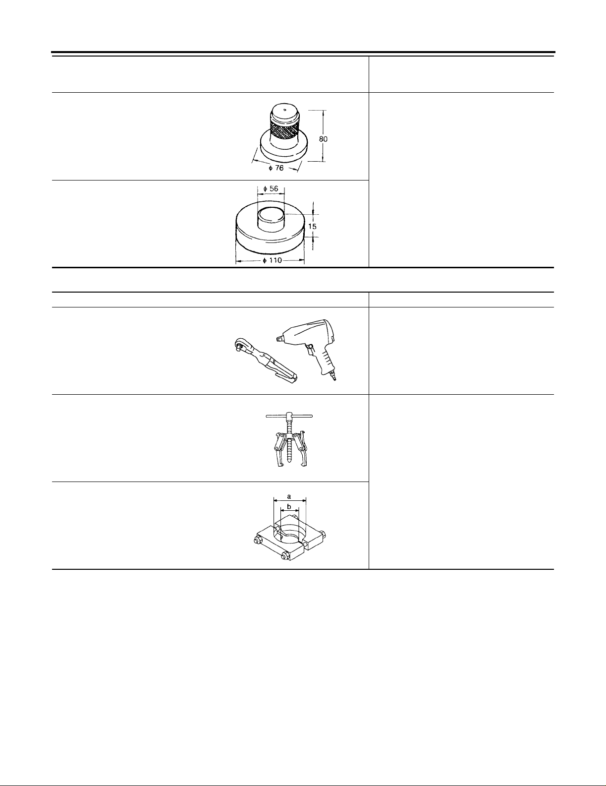
PREPARATION PFP:00002 Special Service Tools ECS00A0P
The actual shapes of Kent-Moore tools may differ from those of spe ci al se rvice tools illustrated here.
Tool number
(Kent-Moore No.)
Tool name
—
(J-34301-C)
Oil pressure gauge set
1 —
(J-34301-1)
Oil pressure gauge
2 —
(J-34301-2)
Hoses
3 —
(J-34298)
Adapter
4 —
(J-34282-2)
Adapter
5 —
(790-301-1230-A)
60° Adapter
6 —
(J-34301-15)
Square socket
KV311J0010
(J-45542)
Adapter
AAT896
Description
Measuring line pressure
Measuring line pressure
KV991J0060
(J-45404)
Alignment tool
ST33290001
(J-34286)
Puller
ST33400001
(J-26082)
Drift
SCIA3019E
Adjusting park/neutral position (PNP) switch
SCIA3018E
● Remov in g oil pum p assembly
● Removing thrust roller bearing
a: 250 mm (9.84 in)
b: 160 mm (6.30 in)
NT414
Installing differential side oil seals
a: 60 mm (2.36 in) dia.
b: 74 mm (1.85 in) dia.
NT086
Revision: July 2005 2005 Maxima
AT-12
Page 13
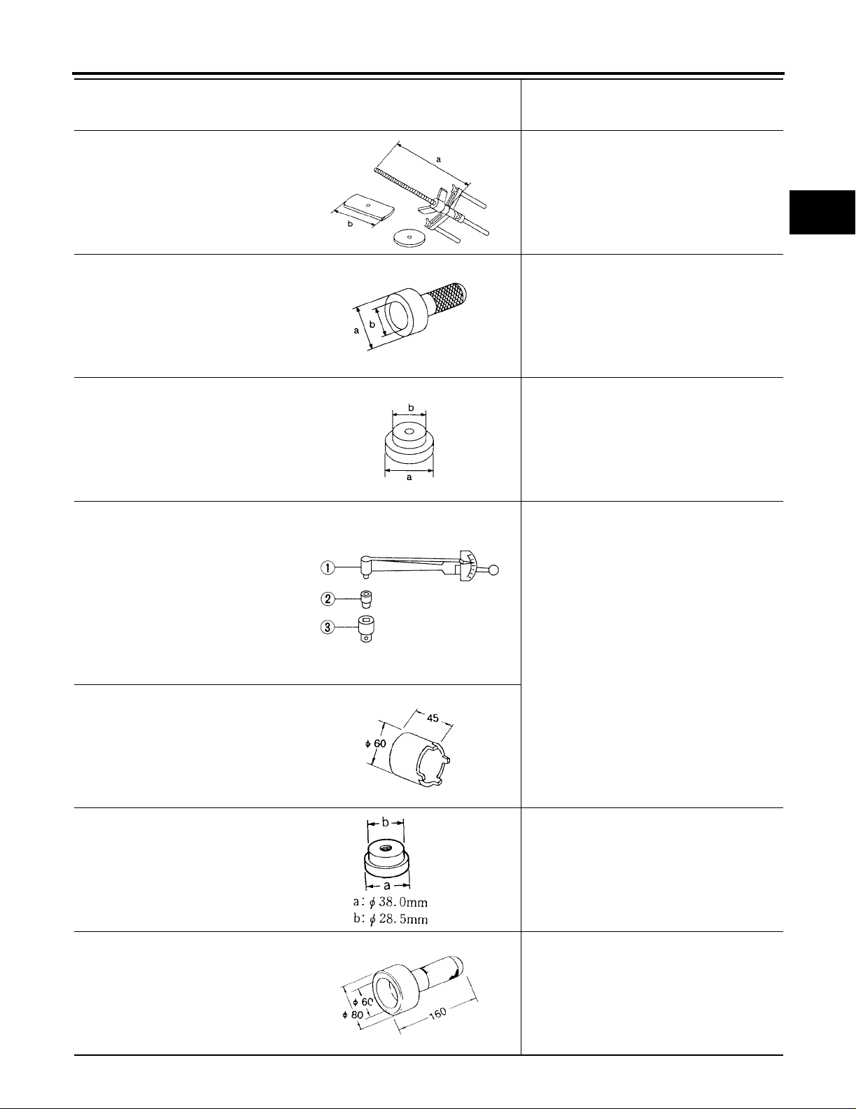
PREPARATION
Tool number
(Kent-Moore No.)
Tool name
KV31102400
(J-34285 and J-34285-87)
Clutch spring compressor
ST30720000
(J-25405)
Drift
ST30612000
(J-25742-2)
Drift
ST3127S000
(J-25765-A)
Preload gauge
1 GG91030000
(J-25765-A)
Torque wrench
2 HT62940000
(—)
Socket adapter
3 HT62900000
(—)
Socket adapter
KV40102500
(J-28815)
Drift
NT423
NT115
NT073
NT124
Description
Removing and installing return springs
a: 320 mm (12.60 in)
b: 174 mm (6.85 in)
● Installing oil seal
● Installing tap e red roller bea ring
a: 77 mm (3.03 in) dia.
b: 55.5 mm (2.185 in) dia.
Removing outer race and adjust shim
a: 62 mm (2.44 in) dia.
b: 40 mm (1.57 in) dia.
Checking differential side bearing preloa d
A
B
AT
D
E
F
G
H
I
J
K
L
ZZC0999D
ST33061000
(J-8107-2)
Drift
ZZC0628D
KV38100500
● Remo vi ng ta per ed roll er be aring
● Remo vi ng m anual val ve oil seal
Installing tapered roller bearing
(—)
Drift
ZZC0809D
Revision: July 2005 2005 Maxima
AT-13
M
Page 14
PREPARATION
Tool number
(Kent-Moore No.)
Description
Tool name
KV40100621
Installing outer race and adjust shim
(J-25273)
Drift
ZZC1026D
ST30022000
(—)
Drift
ZZC0255D
Commercial Service Tools ECS00A0Q
Tool name Description
Power tool Loosening bolts and nuts
PBIC0190E
Puller Removing tapered roller bearing
a: 60 mm (2.36 in) dia.
b: 35 mm (1.38 in) dia.
NT077
Puller
NT411
Revision: July 2005 2005 Maxima
AT-14
Page 15

A/T FLUID
A/T FLUID PFP:KLE40
Changing A/T Fluid ECS00A0R
Refer to MA-22, "Chan gin g A/T Flu id " .
Checking A/T Fluid ECS00A0S
Refer to MA-21, "Checking A/T Fluid" .
A
B
AT
D
E
F
G
H
K
M
I
J
L
Revision: July 2005 2005 Maxima
AT-15
Page 16
A/T CONTROL SYSTEM
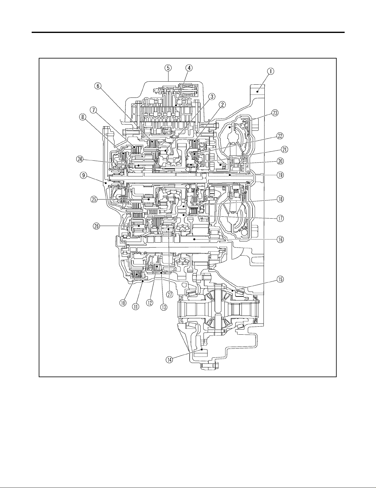
A/T CONTROL SYSTEM PFP:31036 Cross-Sectional View ECS00A0T
SCIA2575E
1. Converter housing 2. 2nd brake 3. One-way clutch No. 2
4. Control valve assembly 5. Side cover 6. 1st and reverse brake
7. Forward clutch 8. Direct clutch 9. Transaxle case cover
10. B5 brake 11. Transaxle case 12. U/D clutch
13. U/D brake 14. Fi nal gear 15. Differential case
16. Output shaft 17. Counter driven gear 18. Counter drive gear
19. Input shaft 20. Oil pump 2 1. One-wa y clutc h No . 1
22. 2nd coast brake 23. Torque converter 24. Main rear planetary gear
25. Main front planetary gear 26. U/D rear planetary gear 27. U/D front planetary gear
Revision: July 2005 2005 Maxima
AT-16
Page 17
A/T CONTROL SYSTEM
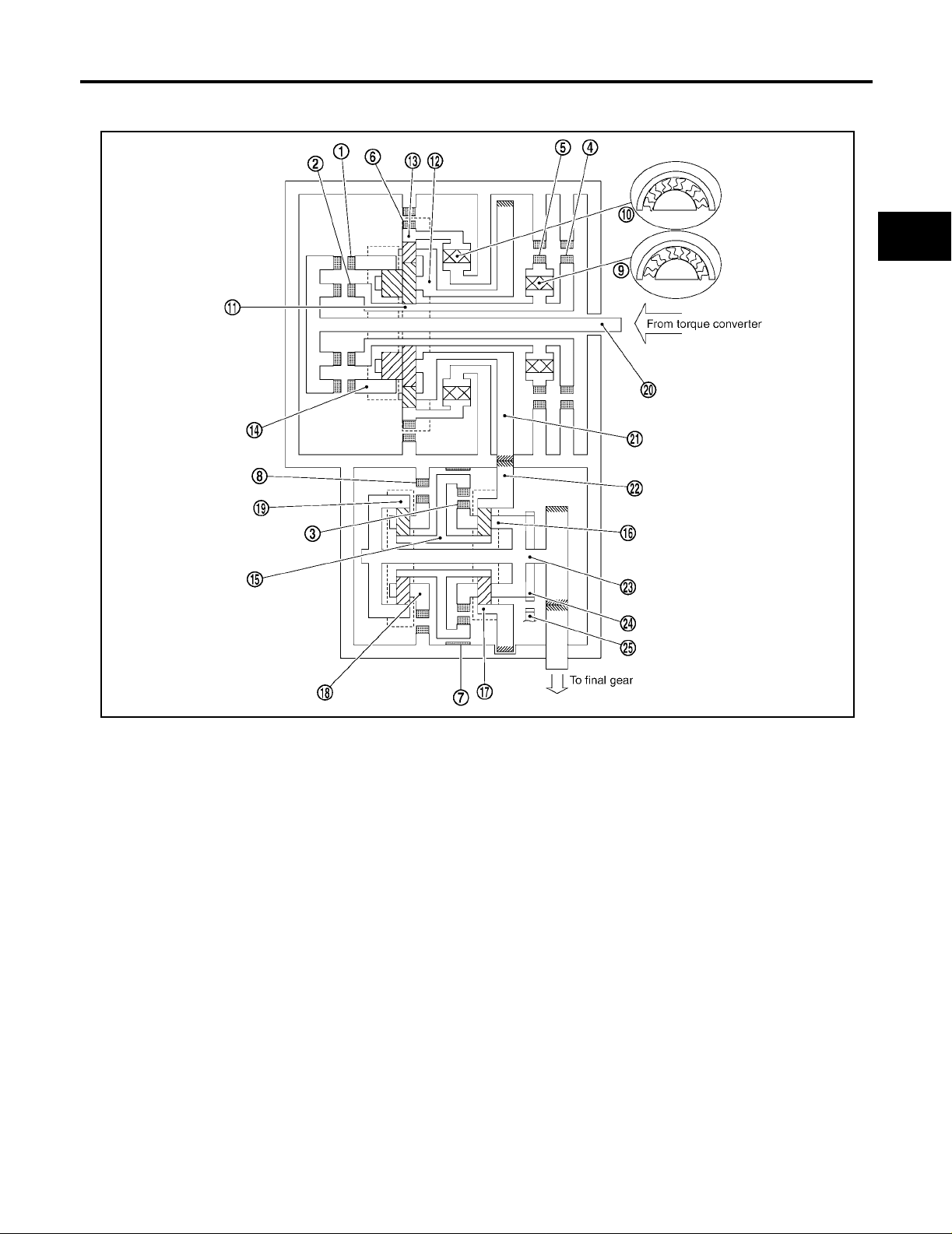
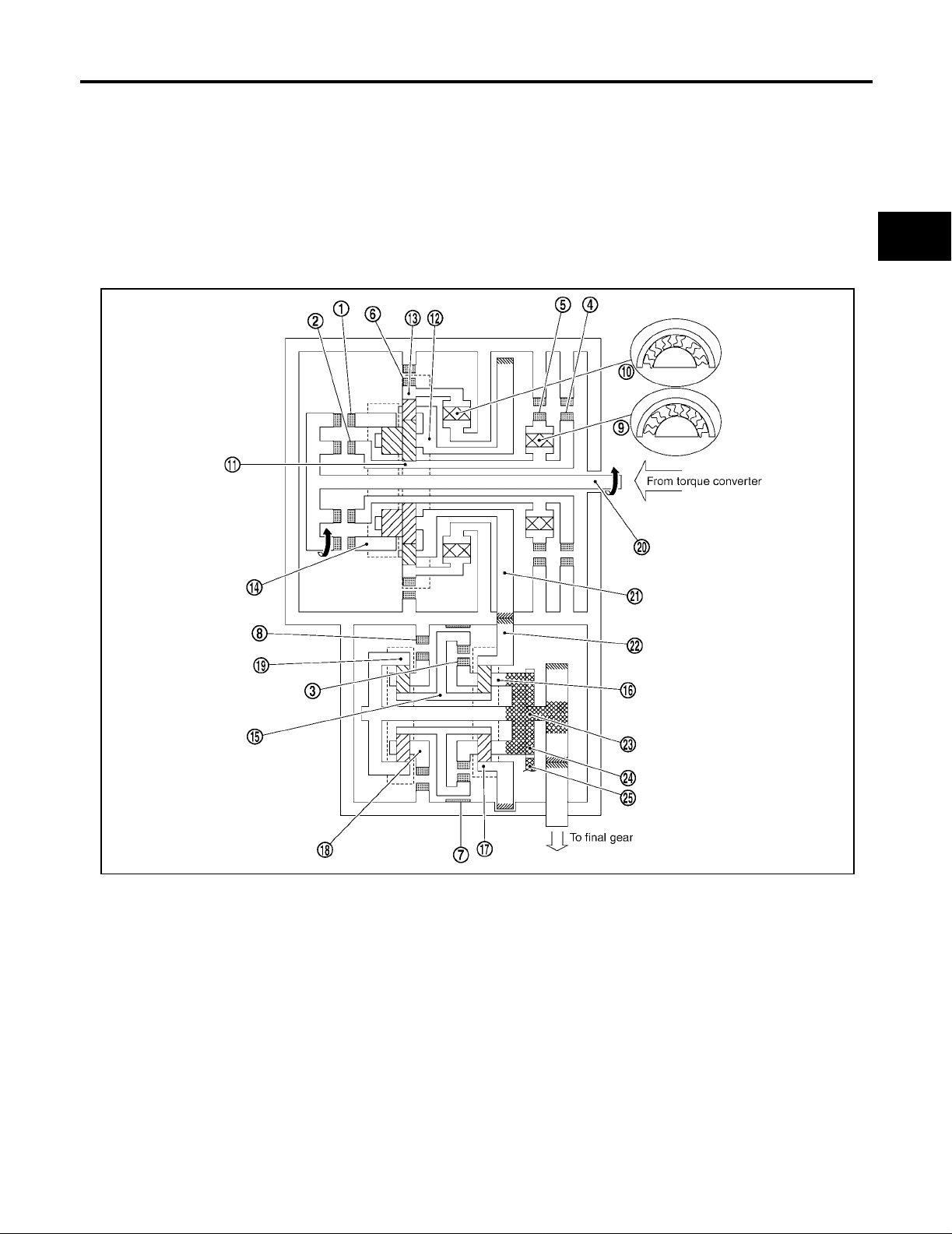
Shift Mechanism ECS00A0U
CONSTRUCTION
A
B
AT
D
E
F
G
1. Forward clutch 2. Direct cl utch 3. U/D clutch
4. 2nd coast brake 5. 2nd brake 6. 1st and reverse brake
7. U/D bra ke 8. B5 brake 9. One-way clutch No. 1
10. One-way clutch No. 2 11. Main sun gear 12. Main planetary carrier
13. Main front internal gear 14. Main rear internal gear 15. U/D sun gear
16. U/D front planetary carrier 17. U/D front internal gear 18. U/D rear pla netary carri er
19. U/D rear internal gear 20. Input shaft 21. Count er driv e gear
22. Counter driven gear 23. Output shaft 24. Parking gear
25. Parking pawl
H
I
J
SCIA2576E
K
L
M
Revision: July 2005 2005 Maxima
AT-17
Page 18
A/T CONTROL SYSTEM
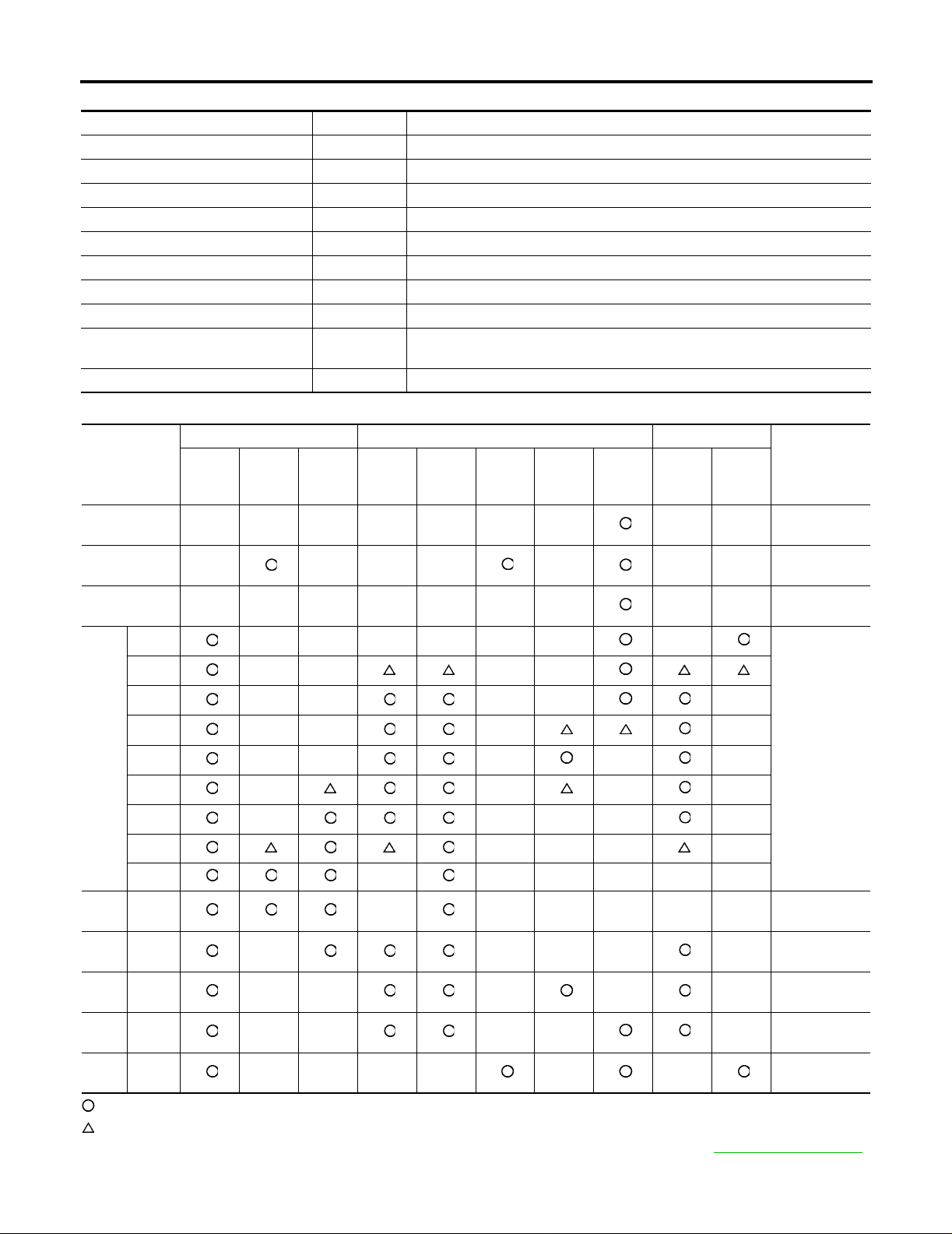
FUNCTION OF CLUTCH AND BRAKE
Clutch and brake components Abbr. Function
Forward clutch 1 F/C Connect input shaft 20 to main rear internal gear 10 .
Direct clutch 2 D/C Connect input shaft 20 to main sun gear 11 .
U/D clutch 3 U/D.C Connect U/D sun gear 15 to U/D front planetary carrier 16 .
2nd coast brake 4 2nd C/B Lock main sun gear 11 .
2nd brake 5 2nd/B Lock counterclockwise rotation of main sun gear 11 .
1st and reverse brake 6 1st & R/B Lock main front internal gear 13 .
U/D brake 7 U/D.B Lock U/D sun gear 15 .
B5 brake 8 B5/B Lock U/D rear planetary carrier 18 .
One-way clutch No. 1 9 O.C1 Lock counterclockwise rotation of main sun gear 11 , when 2nd brake 5 oper-
ations.
One-way clutch No. 2 10 O.C2 Lock counterclockwise rotation of main front internal gear 13 .
CLUTCH AND BAND CHART
Clutch Brake One-way clutch
Shift position
P
R
N
F/C
1
D/C2 U/D.C
3
2nd C/
B
4
2nd/B
5
1st &
R/B
6
U/D.B7B5/B8O.C19O.C2
10
Remarks
PARK
POSITION
REVERSE
POSITION
NEUTRAL
POSITION
1st
1 ⇔ 2
2nd
2 ⇔ 3
D
3rd
3 ⇔ 4
4th
4 ⇔ 5
5th
M5 5th
M4 4th
M3 3rd
M2 2nd
M1 1st
Automatic shift
1 ⇔ 2 ⇔ 3 ⇔
4 ⇔ 5
Locks in 5th
gear*
Locks in 4th
gear*
Locks in 3rd
gear*
Locks in 2nd
gear*
Locks in 1st
gear*
: Operates
: In transition between applied and released.
*: Except when automated up/down shift control and up/down shift permission control are activated. Refer to AT-37, "
Revision: July 2005 2005 Maxima
AT-18
MANUAL MODE" .
Page 19
A/T CONTROL SYSTEM
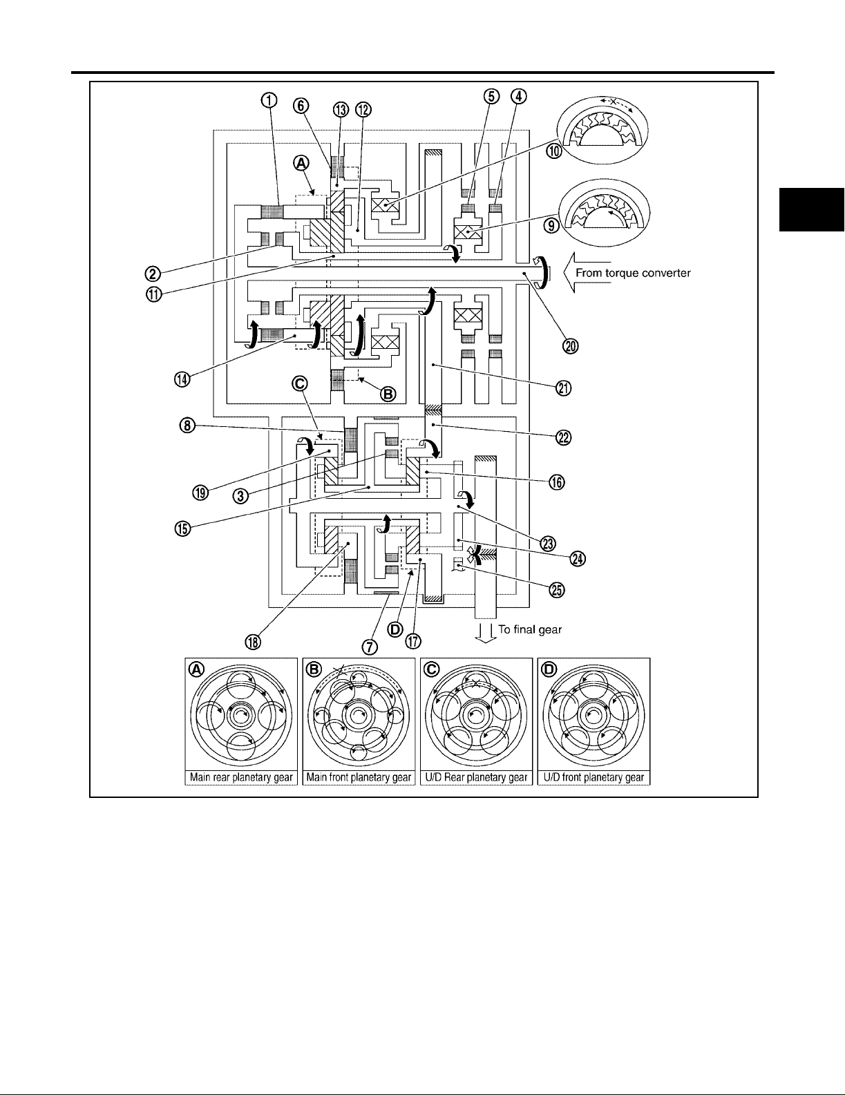
POWER TRANSMISSION
“N” position
Since both th e f orward clutch and the direct clut ch are released, torque from the in pu t s h aft dri ve is not transmitted to the output shaft.
“P” position
● The same as for the “N” position, both the forward clutch and the direct clutch are released, so torque
from the input shaft drive is not transmitted to the output shaft.
● The parking pole linked with the selector lever meshes with the parking gear and fastens the output shaft
mechanically.
A
B
AT
D
E
F
G
1. Forward clutch 2. Direct cl utch 3. U/D clutch
4. 2nd coast brake 5. 2nd brake 6. 1st and reverse brake
7. U/D bra ke 8. B5 brake 9. One-way clutch No. 1
10. One-way clutch No. 2 11. Main sun gear 12. Main planetary carrier
13. Main front internal gear 14. Main rear internal gear 15. U/D sun gear
16. U/D front planetary carrier 17. U/D front internal gear 18. U/D rear pla netary carri er
19. U/D rear internal gear 20. Input shaf t 21. Counter dr ive gear
22. Counter driven gear 23. Output shaft 24. Parking gear
25. Parking pawl
SCIA2577E
H
I
J
K
L
M
Revision: July 2005 2005 Maxima
AT-19
Page 20

A/T CONTROL SYSTEM
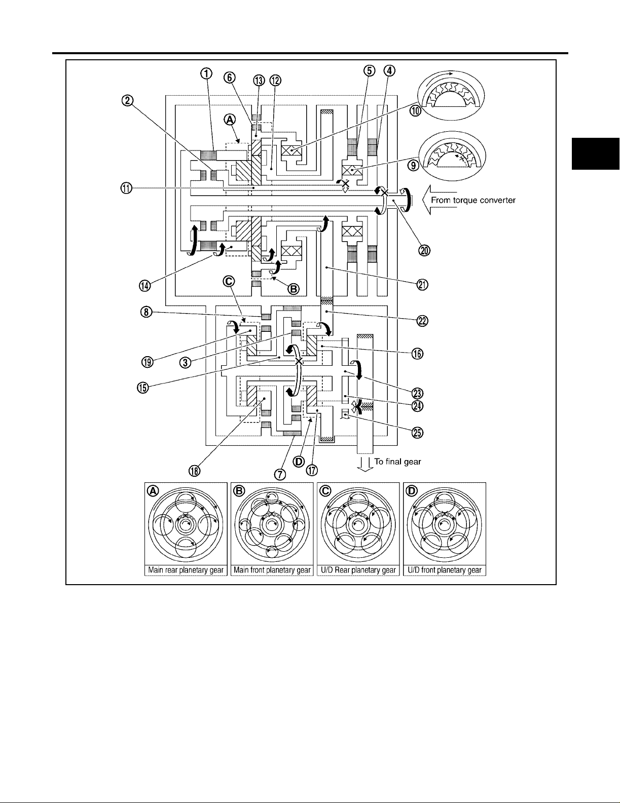
“D” position 1st gear
1. Input shaft rotates clockwise.
2. Forward clutch operates. (Connect input shaft to main rear internal gear.)
3. Main rear internal gear rotates clockwise.
4. Main rear planetary pinion gear rotates itself cloc kwise.
5. Main fron t large planetary pinion gear rotates itself clockwise for rear planetary pinion and one.
6. Main fron t small planetary pinion gear rotates itself counterclockwise.
7. Main front internal gear is going to rotates counterclockwise.
8. One-way clutch No. 2 operates. (Lock counterclockwise rotation of main front inte rnal gear.)
9. Main planetary carrier revolves clockwise due to reaction force of front small planetary pinion gear.
10. Counter drive gear rotates clockwise for main planetary carrier and one.
11. Counter driven gear rotates counterclockwise.
12. U/D front internal gear rotates counterclockwise for counter driven gear and one.
13. U/D front planetary pinion gear rotates itself counterclockwise.
14. U/D sun gear rotates clockwise.
15. U/D rear planetary pinion gear rotates itself counterclockwise.
16. B5 brake operate. (Lock rotation of U/D rear planetary carrier.)
17. U/D rear internal gear rotates counterclockwise.
18. U/D front pla netary carrier and out put shaft rotates counterclockwise for U/D rear internal gear and one.
19. Final gear clockwise.
● During deceleration, main front internal gear clockwise due to rotation itself clockwise of main front small
planetary pinion gear, but driving force loses due to free of one-way clutch No. 2. Therefore, engine brake
does not operate.
Revision: July 2005 2005 Maxima
AT-20
Page 21

A/T CONTROL SYSTEM
A
B
AT
D
E
F
G
1. Forward clutch 2. Direct cl utch 3. U/D clutch
4. 2nd coast brake 5. 2nd brake 6. 1st and reverse brake
7. U/D bra ke 8. B5 brake 9. One-way clutch No. 1
10. One-way clutch No. 2 11. Main sun gear 12. Main planetary carrier
13. Main front internal gear 14. Main rear internal gear 15. U/D sun gear
16. U/D front planetary carrier 17. U/D front internal gear 18. U/D rear pla netary carri er
19. U/D rear internal gear 20. Input shaf t 21. Counter dr ive gear
22. Counter driven gear 23. Output shaft 24. Parking gear
25. Parking pawl
H
I
J
K
L
M
SCIA2585E
Revision: July 2005 2005 Maxima
AT-21
Page 22

A/T CONTROL SYSTEM
“M1” position 1st gear
1. Input shaft rotates clockwise.
2. Forward clutch operates. (Connect input shaft to main rear internal gear.)
3. Main rear internal gear rotates clockwise.
4. Main rear planetary pinion gear rotates itself cloc kwise.
5. Main fron t large planetary pinion gear rotates itself clockwise for rear planetary pinion gear and one.
6. Main fron t small planetary pinion gear rotates itself counterclockwise.
7. Main front internal gear is going to rotates counterclockwise.
8. 1st and reverse brake operates. (L ock rotation of main fr ont internal gear.)
9. Main planetary carrier revolves clockwise due to reaction force of front small planetary pinion gear.
10. Counter drive gear rotates clockwise for main planetary carrier and one.
11. Counter driven gear rotates counterclockwise.
12. U/D front internal gear rotates counterclockwise for counter driven gear and one.
13. U/D front planetary pinion gear rotates itself counterclockwise.
14. U/D sun gear rotates clockwise.
15. U/D rear planetary pinion gear rotates itself counterclockwise.
16. B5 brake operate. (Lock rotation of U/D rear planetary carrier.)
17. U/D rear internal gear rotates counterclockwise.
18. U/D front pla netary carrier and out put shaft rotates counterclockwise for U/D rear internal gear and one.
19. Final gear clockwise.
● During deceleration, driving force i s connected to input shaft direct ly without one-w ay clutch. Th erefore,
engine brake operates.
Revision: July 2005 2005 Maxima
AT-22
Page 23
A/T CONTROL SYSTEM
A
B
AT
D
E
F
G
1. Forward clutch 2. Direct cl utch 3. U/D clutch
4. 2nd coast brake 5. 2nd brake 6. 1st and reverse brake
7. U/D bra ke 8. B5 brake 9. One-way clutch No. 1
10. One-way clutch No. 2 11. Main sun gear 12. Main planetary carrier
13. Main front internal gear 14. Main rear internal gear 15. U/D sun gear
16. U/D front planetary carrier 17. U/D front internal gear 18. U/D rear pla netary carri er
19. U/D rear internal gear 20. Input shaf t 21. Counter dr ive gear
22. Counter driven gear 23. Output shaft 24. Parking gear
25. Parking pawl
H
I
J
K
L
M
SCIA2586E
Revision: July 2005 2005 Maxima
AT-23
Page 24

A/T CONTROL SYSTEM
“D”, “M2” positions 2nd gear
1. Input shaft rotates clockwise.
2. Forward clutch operates. (Connect input shaft to main rear internal gear.)
3. Main rear internal gear rotates clockwise.
4. Main rear planetary pinion gear rotates itself cloc kwise.
5. Main fron t large planetary pinion gear rotates itself clockwise for rear planetary pinion and one.
6. 2nd brake and 2nd coast brake operates.
7. One-way clutch No. 1 operates. (Lock rotation of main sun gear.)
8. Main planetary carrier revol v es clockwise due to reaction force of front large planetary pinion gear.
9. Counter drive gear rotates clockwise for main planetary carrier and one.
10. Counter driven gear rotates counterclockwise.
11. U/D front internal gear rotates counterclockwise for counter driven gear and one.
12. U/D front planetary pinion gear rotates itself counterclockwise.
13. U/D sun gear rotates clockwise.
14. U/D rear planetary pinion gear rotates itself counterclockwise.
15. B5 brake operate. (Lock rotation of U/D rear planetary carrier.)
16. U/D rear internal gear rotates counterclockwise.
17. U/D front pla netary carrier and out put shaft rotates counterclockwise for U/D rear internal gear and one.
18. Final gear clockwise.
● During deceleration, driving force i s connected to input shaft direct ly without one-w ay clutch. Th erefore,
engine brake operates.
Revision: July 2005 2005 Maxima
AT-24
Page 25

A/T CONTROL SYSTEM
A
B
AT
D
E
F
G
1. Forward clutch 2. Direct cl utch 3. U/D clutch
4. 2nd coas t br ake 5. 2nd brake 6. 1st and reverse brake
7. U/D bra ke 8. B5 brake 9. One-way clutch No. 1
10. One-way clutch No. 2 11. Main sun gear 12. Main planetary carrier
13. Main front internal gear 14. Main rear internal gear 15. U/D sun gear
16. U/D front planetary carrier 17. U/D front internal gear 18. U/D rear pla netary carri er
19. U/D rear internal gear 20. Input shaf t 21. Counter dr ive gear
22. Counter driven gear 23. Output shaft 24. Parking gear
25. Parking pawl
H
I
J
K
L
M
SCIA2587E
Revision: July 2005 2005 Maxima
AT-25
Page 26

A/T CONTROL SYSTEM
“D”, “M3” positions 3rd gear
1. Input shaft rotates clockwise.
2. Forward clutch operates. (Connect input shaft to main rear int ernal gear.)
3. Main rear internal gear rotates clockwise.
4. Main rear planetary pinion gear rotates itself cloc kwise.
5. Main fron t large planetary pinion gear rotates itself clockwise for rear planetary pinion and one.
6. 2nd brake and 2nd coast brake operates.
7. One-way clutch No. 1 operates. (Lock rotation of main sun gear.)
8. Main planetary carrier revol v es clockwise due to reaction force of front large planetary pinion gear.
9. Counter drive gear rotates clockwise for main planetary carrier and one.
10. Counter driven gear rotates counterclockwise.
11. U/D front internal gear rotates counterclockwise for counter driven gear and one.
12. U/D front planetary pinion gear rotates itself counterclockwise.
13. U/D brake operate. (Lock rotation of U/D sun gear.)
14. U/D fron t planetary carrier re volves counterc lockwise due to reaction force of U/D front pl anetary pinion
gear.
15. U/D rear internal gear and output shaft rotates counterclockwise for U/D front planetary carrier and one.
16. Final gear clockwise.
● During deceleration, driving force i s connected to input shaft direct ly without one-w ay clutch. Th erefore,
engine brake operates.
Revision: July 2005 2005 Maxima
AT-26
Page 27
A/T CONTROL SYSTEM
A
B
AT
D
E
F
G
1. Forward clutch 2. Direct cl utch 3. U/D clutch
4. 2nd coast brake 5. 2nd brake 6. 1st and reverse brake
7. U/D bra ke 8. B5 brake 9. One-way clutch No. 1
10. One-way clutch No. 2 11. Main sun gear 12. Main planetary carrier
13. Main front internal gear 14. Main rear internal gear 15. U/D sun gear
16. U/D front planetary carrier 17. U/D front internal gear 18. U/D rear pla netary carri er
19. U/D rear internal gear 20. Input shaf t 21. Counter dr ive gear
22. Counter driven gear 23. Output shaft 24. Parking gear
25. Parking pawl
H
I
J
K
L
M
SCIA2588E
Revision: July 2005 2005 Maxima
AT-27
Page 28

A/T CONTROL SYSTEM
“D”, “M4” positions 4th gear
1. Input shaft rotates clockwise.
2. Forward clutch operates. (Connect input shaft to main rear internal gear.)
3. Main rear internal gear rotates clockwise.
4. Main rear planetary pinion gear rotates itself cloc kwise.
5. Main fron t large planetary pinion gear rotates itself clockwise for rear planetary pinion and one.
6. 2nd brake and 2nd coast brake operates.
7. One-way clutch No. 1 operates. (Lock rotation of main sun gear.)
8. Main planetary carrier revol v es clockwise due to reaction force of front large planetary pinion gear.
9. Counter drive gear rotates clockwise for main planetary carrier and one.
10. Counter driven gear rotates counterclockwise.
11. U/D front internal gear rotates counterclockwise for counter driven gear and one.
12. U/D clutch operate. (Connect U/D sun gear to U/D front planetary carrier.)
13. U/D front planetary pinion gear cannot rotate itself, and U/D unit rotates counterclockwise as one.
14. Output shaft rotates counterclockwise for U/D unit and one.
15. Final gear clockwise.
● During deceleration, driving force i s connected to input shaft direct ly without one-w ay clutch. Th erefore,
engine brake operates.
Revision: July 2005 2005 Maxima
AT-28
Page 29

A/T CONTROL SYSTEM
A
B
AT
D
E
F
G
1. Forward clutch 2. Direct cl utch 3. U/D clutch
4. 2nd coast brake 5. 2nd brake 6. 1st and reverse brake
7. U/D bra ke 8. B5 brake 9. One-way clutch No. 1
10. One-way clutch No. 2 11. Main sun gear 12. Main planetary carrier
13. Main front internal gear 14. Main rear internal gear 15. U/D sun gear
16. U/D front planetary carrier 17. U/D front internal gear 18. U/D rear pla netary carri er
19. U/D rear internal gear 20. Input shaf t 21. Counter dr ive gear
22. Counter driven gear 23. Output shaft 24. Parking gear
25. Parking pawl
H
I
J
K
L
M
SCIA2592E
Revision: July 2005 2005 Maxima
AT-29
Page 30

A/T CONTROL SYSTEM
“D”, “M5” positions 5th gear
1. Input shaft rotates clockwise.
2. Forward clutch operates. (Connect input shaft to main rear internal gear.)
3. Direct clutch operates. (Connect input shaft to main sun gear.)
4. Main rear planetary pinion gear cannot rotate itself, and main rear planetary unit rotates clockwise as one.
5. Main front large planetary pinion gear cannot rotate itself for main rear planetary pinion gear and one, and
main front planetary unit rotates clockwise as one.
6. Counter drive gear rotates clockwise for main front pla netary unit and one.
7. Counter driven gear rotates counterclockwise.
8. U/D front internal gear rotates counterclockwise for counter driven gear and one.
9. U/D clutch operate. (Connect U/D sun gear to U/D front planetary carrier.)
10. U/D front planetary pinion gear cannot rotate itself, and U/D unit rotates counterclockwise as one.
11. Output shaft rotates counterclockwise for U/D unit and one.
12. Final gear clockwise.
● During deceleration, driving force i s connected to input shaft direct ly without one-w ay clutch. Th erefore,
engine brake operates.
Revision: July 2005 2005 Maxima
AT-30
Page 31

A/T CONTROL SYSTEM
A
B
AT
D
E
F
G
1. Forward clutch 2. Direct cl utch 3. U/D clutch
4. 2nd coast brake 5. 2nd brake 6. 1st and reverse brake
7. U/D bra ke 8. B5 brake 9. One-way clutch No. 1
10. One-way clutch No. 2 11. Main sun gear 12. Main planetary carrier
13. Main front internal gear 14. Main rear internal gear 15. U/D sun gear
16. U/D front planetary carrier 17. U/D front internal gear 18. U/D rear pla netary carri er
19. U/D rear internal gear 20. Input shaf t 21. Counter dr ive gear
22. Counter driven gear 23. Output shaft 24. Parking gear
25. Parking pawl
H
I
J
K
L
M
SCIA2593E
Revision: July 2005 2005 Maxima
AT-31
Page 32

A/T CONTROL SYSTEM
“R” position
1. Input shaft rotates clockwise.
2. Direct clutch operates. (Connect input shaft to main sun gear.)
3. Main sun gear rotates clockwise.
4. Main rear planetary pinion gear rotates itself cloc kwise.
5. Main front large planetary pinion gear rotates itself counterclockwise for rear planetary pinion gear and
one.
6. Main fron t small planetary pinion gear rotates itself clockwise.
7. 1st and reverse brake operates. (L ock rotation of main fr ont internal gear.)
8. Main planet a ry car rier revolve s coun ter cloc kwise due to re acti on forc e of fr ont sma ll pl anet ar y pini on gea r.
9. Counter drive gear rotates counterclockwise for main planetary carrier and one.
10. Counter driven gear rotates clockwise.
11. U/D front internal gear rotates clockwise for counter driven gear and one.
12. U/D front planetary pinion gear rotates itself clockwise.
13. U/D sun gear rotates counterclo ckwise.
14. U/D rear planetary pinion gear rotates itself clockw ise.
15. B5 brake operate. (Lock rotation of U/D rear planetary carrier.)
16. U/D rear internal gear rotates clockwise.
17. U/D front pla netary carrier and out put shaft rotates clockw ise for U/D rear internal gear and one.
18. Final gear counterclockwise.
● During deceleration, driving force i s connected to input shaft direct ly without one-w ay clutch. Th erefore,
engine brake operates.
Revision: July 2005 2005 Maxima
AT-32
Page 33

A/T CONTROL SYSTEM
A
B
AT
D
E
F
G
1. Forward clutch 2. Direct cl utch 3. U/D clutch
4. 2nd coast brake 5. 2nd brake 6. 1st and reverse brake
7. U/D bra ke 8. B5 brake 9. One-way clutch No. 1
10. One-way clutch No. 2 11. Main sun gear 12. Main planetary carrier
13. Main front internal gear 14. Main rear internal gear 15. U/D sun gear
16. U/D front planetary carrier 17. U/D front internal gear 18. U/D rear pla netary carri er
19. U/D rear internal gear 20. Input shaf t 21. Counter dr ive gear
22. Counter driven gear 23. Output shaft 24. Parking gear
25. Parking pawl
H
I
J
K
L
M
SCIA2594E
Revision: July 2005 2005 Maxima
AT-33
Page 34

A/T CONTROL SYSTEM
TCM Function ECS00A0V
The function of the TCM is to:
● Receive input signals sent from various switches and sensors.
● Determine required line pressure, shifting point, lock-up operation, and engine brake operation.
● Send required output signals to the respective solenoids.
CONTROL SYSTEM OUTLINE
The automatic transaxle senses ve hicle operating conditions through various sensors or signals. It always
controls the optimum shift position and reduces shifting and lock-up shocks.
SENSORS (or SIGNAL)
PNP switch
Throttle angle signal
Throttle position signal
Engine speed signal
Engine torque signal
A/T fluid temperature sensor
Revolution sensor
Turbine revolution sensor
Vehicle speed signal
Manual mode switch signal
Stop lamp swit ch si gna l
Þ
Shift control
Line pressure control
Lock-up control
Engine brake control
Timing control
Fail-safe control
Self-diagnosis
CONSULT-II communication line
CAN communication line
On board diagnosis
TCM
Þ
ACTUATORS
Shift solenoid valve A
Shift solenoid valve B
Shift solenoid valve C
Shift solenoid valve D
Shift solenoid valve E
Pressure control solenoid valve A
Pressure control solenoid valve B
Pressure control solenoid valve C
A/T CHECK indicator lamp
CONTROL SYSTEM DIAGRAM
WCIA0445E
Revision: July 2005 2005 Maxima
AT-34
Page 35

A/T CONTROL SYSTEM
Input/Output Signal of TC M ECS00A0W
Line
Control item
Throttle angle signal
Throttle position signal
Revolution sensor XXXXXXX
Turbine revolution sensor X X X X X X
Vehicle speed signal MTR
Engine speed signals
Engine torque signals
Input
PNP switch XXXXXX
Manual mode switch X X X X X
Stop lamp swit ch si gna l
A/T fluid temperature sensor XXXXXX
ASCD
TCM power supply voltage signal X X XXXXX
Shift solenoid valve A/B/C/D/E X X X X
Pressure control solenoid valve AXXXXXXX
Out-
Pressure control solenoid valve B X X X X X
put
Pressure control solenoid valve C X X X X
Self-diagnostics table
*1: Spare for revolution sensor
*2: Spare for throttle angle signal
*3: If these input and output signals are different, the TCM triggers th e fail -s afe function.
*4: Used as a condition for starting self-diagnostic s; if self-diagnostics are not started, it is judged that there is some kind of error.
*5: CAN communications.
Operation signal
Overdrive cancel signal
(*5)
(*5)
(*1) (*5)
(*5)
(*5)
(*5)
(*5)
(*5)
(*5)
pressure
control
XXXXXXX
(*2)
X
XXXX XX
XXXXX X
Vehicle
speed
control
(*2)
X
XXX XX
XXX
XXX
X X X
Shift
control
Lock-up
control
X
Engine
brake
control
(*2)
X
Fail-safe
function
(*3)
Self-diag-
nostics
function
(*4)
X
(*4)
X
(*4)
X
X
A
B
AT
D
E
F
G
H
I
J
K
CAN Communication ECS00A0X
SYSTEM DESCRIPTION
CAN (Controller Area Network) is a serial communication line for real time application. It is an on-vehicle multiplex communication line with high data communication speed and excellent error detection ability. Many electronic control units are equipped onto a vehicle, and each control unit shares information and links with other
control units during opera tion (not independent). In CA N communication, cont rol units are connected with 2
communicatio n lines ( CAN H lin e, CAN L li ne) al lowi ng a high rate of in forma tio n trans missi on wi th less w iring .
Each control unit transmits/receives data but selectively reads required data only.
For details, refer to LAN-7, "
Revision: July 2005 2005 Maxima
CAN COMMUNICATION" .
AT-35
L
M
Page 36

A/T CONTROL SYSTEM
Line Pressure Control ECS00A0Y
● The pressure control solenoid valve A controls linear line pressure by control signal from TCM and line
pressure for clutches and brakes to reduce shift shock.
● This pressure control solenoid valve A controls the pressure regulator valve as the signal pressure and
adjusts the pressure o f the op eratin g oil d isch arged from th e oil p ump to th e line press ure mo st ap propri ate to the driving state.
SCIA2605E
LINE PRESSURE CONTROL IS BASED ON THE TCM LINE PRESSURE CHARACTERISTIC PATTERN
In order to obtain the m ost approp riate li ne pressure charac teristic to meet the cu rrent drivi ng state, the TCM
controls the pressure control solenoid valve A current and thus controls the line pressure.
Shift Control ECS00A0Z
The clutch pre ssure control solenoid is c ontrolled by the signals f rom the switches and sensors . Thus, the
clutch pressure is adjusted to be appropriate to th e engine load state and vehicle dri ving state. It becomes
possible to fin el y con tr ol the c lu tch hy dr a uli c p r essu r e wi t h hi gh p rec is io n an d a smo ot h er s hi f t ch an ge c har acteristic is attained.
SCIA2610E
Basically TCM programmed for economy mode, but TCM changes to several shift schedule automatically
according to s pecified condition.
Revision: July 2005 2005 Maxima
AT-36
Page 37

A/T CONTROL SYSTEM
SPECIAL SHIFT MODE
Upslope Mode
When TCM detects upslope from load of engine torque and decrease of acceleration, this mode changes shift
points in high-speed side accordi ng to the upslope degr ee and avoids busy shift of A/T.
Downslope Mode
When TCM detects downsl ope from increase of accelerat ion with accelerator full clos e, this mode operates
moderate engine brake by changing shift points in high-speed side.
Hot Mode Control
This control lowers ATF temperature by changi ng shift points when t he temperature is extre mely high.
MANUAL MODE
Driver oneself can s ele c t f avorite gear and enjoy sports driv in g of man ua l tran s mi ss io n se ns e by sh ifti ng lever
from D position to manual mode po si tio n an d + (u p sh ift) / - (down shi ft). Bu t l oc k -up c on trol i s op era t e d a ut omatically. Shift control is operated again by shifting from manual gear position to D position. Following control
is operated when manual mode.
A
B
AT
D
E
Automated Up Shift Control
In order to avoid the o ver speed of the eng ine, up shift operate automatically, if it becomes over a cons tant
vehicle speed.
Automated Down Shift Control
In order to avoid the stall of the engine, down shift operate automatically, if it becomes under a constant vehicle speed.
Up Shift Permission Control
In order to avoid the stall of the engine, up shift is done only at over a constant vehicle speed.
Down Shift Permission Control
In order to avoid the over speed of the engine, down shift is done only at under a constant vehicle speed.
UP/DOWN SHIFT LEARNING CONTROL
This control lea rns th e pr essu re to ea ch c lutch or brak e i n order to redu ce sh ift ing sh ock at each s hifti ng (Up,
Down, Manual down, Coast down).
N-D SHIFT CONTROL
This control improve s the N-D sh ift quality due to controll ing line pressure solen oi d va lv e ac co rd ing to forw a rd
clutch piston s tro ke l ea rne d in N-D shif t lea r ning co nt ro l an d ap pl yi ng bes t hy dra ul ic p res sure t o for wa r d cl ut ch
at N-D shift.
N-D SHIFT LEARNING CONTROL
This control learns the forward clutch hydraulic pressure due to monitoring a forward clutch engaging time and
a rotation change rate.
N-R SHIFT CONTROL
This control imp roves the N- R shift qualit y due to cont rolling shif t pressure so lenoid valve according to direct
clutch piston stroke learned in N-R shift learning control and applying best hydraulic pressure to direct clutch
at N-R shift.
F
G
H
I
J
K
L
M
N-R SHIFT LEARNING CONTROL
This control learns the direct clutch hydraulic pressure due to monitoring a direct clutch engaging time and a
rotation change rate.
TORQUE REDUCTION CONTROL
This control improves the shift quality due to sending torque reduction request signal from TCM to ECM and
cutting engine torque increase of shift at N-D shift, N-R shift and 1 ⇔ 2 ⇔ 3 ⇔ 4 ⇔ 5.
If accelerator p edal is depressed rapi dly, this con trol establishes the uppe r limit value of engin e torque and
avoids engine flare at 2 ⇔ 3, 3 ⇔ 4 and 4 Þ 2 of clutch to clutch shift.
Revision: July 2005 2005 Maxima
AT-37
Page 38

A/T CONTROL SYSTEM
Lock-Up Control ECS00A10
The torque conve rter clutch piston in the torque conv erter is engaged to eliminate torqu e converter slip to
increase power transmission efficiency.
The torque converter clutch control valve operation is controlled by the pressure control solenoid valve C,
which is controlled by a signal from TCM, and the torque converter clutch control valve engages or releases
the torque converter clutch piston.
Lock-up Operation Condition Table
Selector lever D position M5 position M4 position M3 position
Gear position 5 4 5 4 3
Lock-up × – ×××
Slip lock-up ××–––
TORQUE CONVERTER CLUTCH CONTROL VALVE CONTROL
Lock-up Contr ol System Diagram
SCIA2612E
Lock-up Released
● In the lock-up released state, the torque converter clutch control valve is set into the unlocked state by the
pressure control solenoid valve C and the lock-up apply pressure is drained.
In this way, the torque converter clutch piston is not coupled.
Lock-up Applied
● In the lock-up applied state, the torque converter clutch control valve is set into the locked state by the
pressure control solenoid valve C and lock-up apply pressure is generated.
In this way, the torque converter clutch piston is pressed and coupled.
Revision: July 2005 2005 Maxima
AT-38
Page 39

A/T CONTROL SYSTEM
SMOOTH LOCK-UP CONTROL
When shifting fro m the lock -up released state to the lock-up ap plied state, the current ou tput to the pressure
control solenoid valve C is controlled with the TCM. In this way, when shifting to the lock-up applied state, the
torque converter clutch is temporarily set to the half-clutched state to reduce the shock.
Half-Clutched State
● The current output from the TCM to the pressure control solenoid valve C is varied to steadily increase the
pressure control solenoid valve C pressure.
In this way, the lock-up apply pressure gradually rises and while the torque convert er clutch pisto n is put
into half-clutc hed status, the to rque conv erter clutch piston ope rating pres sure is incr eased and the coupling is completed smoothly.
Slip Lock-up Control
● In the slip region, the pressure control solenoid valve C current is controlled with the TCM to put it into the
half-clutched state. This absorbs the engine torque fluctuation and lock-up operates from low speed.
This raises the fuel efficiency for 4th and 5th gears at both low speed and when the acceler ator has a low
degree of opening.
A
B
AT
D
E
F
G
H
K
M
I
J
L
Revision: July 2005 2005 Maxima
AT-39
Page 40

ON BOARD DIAGNOSTIC (OBD) SYSTEM
ON BOARD DIAGNOSTIC (OBD) SYSTEM PFP:00028 Introduction ECS00A11
The A/T system has two self-diagnostic systems.
The first is the emission-related on board diagnostic system (OBD-II) performed by the TCM in combination
with the ECM. The malfunction is indicated by the MIL (malfunction indicator lamp) and is stored as a DTC in
the ECM memory but not the TCM memory.
The second is the TCM original self-diagn os is ind ic at ed by th e A/ T CHECK indicator lamp. Th e m alfunction is
stored in the TCM memory. The detected items are overlapped with OBD-II self-diagnostic items. For detail,
refer to AT-75, "
SELF-DIAG RESULT MODE" .
OBD-II Function for A/T System ECS00A12
The ECM provides emission-related on board diagnostic (OBD-II) functions for the A/T system. One function
is to receive a signal from the TCM used with OBD-related parts of the A/T system. The signal is sent to the
ECM when a mal function occurs in the corre sponding OBD-related part. The other function is to ind icate a
diagnostic result by means of the MIL (malfunction indicator lamp) on the instru ment panel. Sensors, switches
and solenoid valves are used as sensing elements.
The MIL automatically illuminates in One or Two Trip Detection Logic when a malfunction is sensed in relation
to A/T system parts.
One or Two Trip Detection Logic of OBD-II ECS00A13
ONE TRIP DETECTION LOGIC
If a malfunction is sensed during the first test drive, the MIL will illuminate and the malfunction will be stored in
the ECM memory as a DTC. The TCM is not provided with such a memory funct ion.
TWO TRIP DETECTION LOGIC
When a malfuncti on is sensed during the fi rst test drive, it is stored in the ECM memory as a 1st trip DT C
(diagnostic trouble code) or 1st trip freeze frame data. At this point, the MIL will not illuminate. — 1st Trip
If the same malf unction as that experien ced during the first test drive is sense d during the second te st drive,
the MIL will illuminate. — 2nd Trip
The “trip” in the “One or Two Trip Detection Logic” means a driving mode in which self-diagnosis is performed
during vehicle operation.
OBD-II Diagnostic Trouble Code (DTC) ECS00A14
HOW TO READ DTC AND 1ST TRIP DTC
DTC and 1st trip DTC can be read by the following methods.
( with CONSULT-II or GST) CONSULT-II or GST (Generic Scan Tool) Examples: P0705, P0710 etc.
These DTC are prescribed by SAE J2012.
(CONSULT-II also displays the malfu nctioning component or system.)
● 1st trip DTC No. is the same as DTC No.
● Output of the diagnostic trouble c ode indica tes that the in dicated circ uit has a malfu nction. How-
ever, in case of the Mode II and GST , they do not indicate whether the malfunction is still occurring
or occurred in the past and returned to normal.
CONSULT-II can identify them as shown below, therefore, CONSULT-II (if available) is recommended.
A sample of CONSULT-II display for DTC and 1st trip DTC is shown
on the next page. DTC or 1st trip D TC of a malf unction is displaye d
in SELF-DIAGNOSTIC RESULTS mode for “ENGINE” with CONSULT-II. Time data indicates ho w ma ny ti me s the vehicle wa s driven
after the last detection of a DTC.
BCIA0030E
Revision: July 2005 2005 Maxima
AT-40
Page 41

ON BOARD DIAGNOSTIC (OBD) SYSTEM
If the DTC is being detected currently, the time data will be “0”.
If a 1st trip DTC is stored in the ECM, the time data will be “1t”.
A
B
AT
SAT015K
D
E
F
G
SAT016K
Freeze Frame Data and 1st Trip Freeze Frame Data
The ECM has a me mory function, whic h stores the driving c ondition such as fuel s ystem status, calcul ated
load value, engin e coolant temperature, short te rm fuel trim, long term fuel trim, engin e speed and vehicle
speed at the moment the ECM detects a malfunction.
Data which are stored in the ECM memory, along with the 1st trip DTC, are called 1st trip freeze frame data,
and the data, s tored to gether with t he DTC data, a re call ed freez e fram e data an d disp layed on CO NSULT-II
or GST. The 1st trip freeze frame data can only be displayed on the CONSULT-II screen, not on the GST. For
detail, refer to EC-54, "
FREEZE FRAME DATA AND 1ST TRIP FREEZE FRAME DATA" .
Only one set of freeze frame data (either 1st trip freeze frame data or freeze frame data) can be stored in the
ECM. 1st trip freeze frame data is stored in the ECM memory along with the 1st trip DTC. There is no priority
for 1st trip freeze fr ame data and it is update d each time a different 1st trip DTC is det ected. However, once
freeze frame data (2nd trip detection/MIL on) is stored in the ECM memory, 1st trip freeze frame data is no
longer stored. R eme mber, only one set of free ze fra me da ta can be stored in the ECM . The ECM has th e following pri orities to update the data.
Priority Items
1
2 Except the above items (Includes A/T related item s)
3 1st trip freeze fr ame data
Freeze frame data
Misfire — DTC: P0300 - P0306
Fuel Injection System Function — DTC: P0171, P0172, P0174, P0175
Both 1st trip free ze frame data a nd f reeze fr ame data (al ong w ith t he D TC) are clea red w hen the ECM m emory is erased.
HOW TO ERASE DTC
The diagnostic trouble code can be erased by CONSULT-II, GST or ECM DIAGNOS TIC TEST MODE as
described followi ng .
● If the battery cable is disconnected, the diagnostic trouble code will be lost within 24 hours.
● When you erase the DTC, using CONSULT-II or GST is easier and quicker than switching the mode
selector on t he ECM.
The following emi ssion-related diagnostic inf ormation is cleared from the ECM m emory when erasing DTC
related to OBD-II. For details, refer to EC-50, "
● Diagnostic trouble codes (DTC)
● 1st trip diagnostic trouble codes (1st trip DTC)
● Freeze frame data
EMISSION-RELATED DIAGNOSTIC INFORMATION ITEMS" .
H
I
J
K
L
M
Revision: July 2005 2005 Maxima
AT-41
Page 42

ON BOARD DIAGNOSTIC (OBD) SYSTEM
● 1st trip freeze frame data
● System rea diness test (SRT) codes
● Test values
HOW TO ERASE DTC (WITH CONSULT-II)
● If a DTC is displayed for both ECM and TCM, it is necessary to be erased for both ECM and TCM.
1. If the ignition switc h stays “ON” after repair work, be sure to tur n ignit ion sw itch “O FF” onc e. Wait at least
10 seconds and t hen turn it “ON” (engine stopped) again.
2. Turn CONSULT-II “ON” and touch “A/T”.
3. Touch “SELF-DIAG RESULTS”.
4. Touch “ERASE”. (The DTC in the TCM will be erased.) Then t o uch “BACK” twice.
5. Touch “ENGINE”.
6. Touch “SELF-DIAG RESULTS”.
7. Touch “ERASE”. (The DTC in the ECM will be erased.)
WCIA0405E
HOW TO ERASE DTC (WITH GST)
1. If the ignition switc h stays “ON” after repair work, be sure to tur n ignit ion sw itch “O FF” onc e. Wait at least
10 seconds and t hen turn it “ON” (engine stopped) again.
2. Erase DTC with TCM. Refer to AT-82, "
Erase self-diagnos is" . (The engin e wa rm-up ste p can b e ski pped
when performing the diagnosis only to erase the DTC.)
3. Select Mode 4 with Generic Scan Tool (GST). For details, refer to EC-143, "
Generic Scan Tool (GST)
Function" .
HOW TO ERASE DTC (NO TOOLS)
The A/T CHECK indicator lamp is located on the instrument p anel.
Revision: July 2005 2005 Maxima
AT-42
Page 43

ON BOARD DIAGNOSTIC (OBD) SYSTEM
1. If the ignition swi tch stays “ON” after repair work, be su re to turn ign ition swit ch “OF F” once. Wait at least
10 seconds and then turn it “ON” (engine stopped) again.
2. Erase DTC with TCM. Refer to AT-82, "
Erase self-diagnosis" . (The engine warm -up s tep ca n be sk ippe d
when performing the diagnosis only to erase the DTC.)
3. Erase DTC with ECM. Refer to EC-62, "
How to Erase DTC" .
Malfunction Indicator Lamp (MIL) ECS00A15
DESCRIPTION
The MIL is located on the instrument panel.
1. The MIL will light up w hen th e ign iti on swi tch i s tu rned “ON ” wi thout the engine running. This is a bulb check.
● If the MIL does not light up, refer to DI-41, "WARNING LAMPS" ,
or see EC-64, "
2. When the engine is started, the MIL s hould go off.
If the MIL remains on, the on board diagnostic system has
detected an engine system malfunction.
Malfunction Indicator Lamp (MIL)" .
A
B
AT
D
E
SEF217U
F
G
H
I
J
K
L
M
Revision: July 2005 2005 Maxima
AT-43
Page 44

TROUBLE DIAGNOSIS
TROUBLE DIAGNOSIS PFP:00004 DTC Inspection Priority Chart ECS00A16
If some DTCs are displayed at the same time, perform inspections one by one based on the following priority
chart.
NOTE:
If DTC U1000 is displayed with other DTCs, first perform the trouble diagnosis for DTC U1000. Refer to
AT-83
.
Priority Detected items (DTC)
1 U1000 CAN communication line
2 Except above
Fail-Safe ECS00A17
The TCM has an electrical fail-safe mode. This mode makes it possible to operate even if there is a malfunction in a main electronic control input/output signal circu it.
In fail-safe mo de, a d riving cond it ion is sele cted acco rding to the m alfu nctio ning loca tion, a nd lin e pr ess ure is
set at the maximum. For this reason, the customer will be subjected to uncomfortable “slipping” or “poor acceleration” of the vehicle.
In that case, handle according to the “diagnostics flow” (Refer to AT-48
FAIL- SAFE FUNCTION
If any malfunction occurs in a sensor or solenoid, this function controls the A/T to make driving possible.
NOTE:
Line pressure i s set at the maximum in fail-safe mode . Although gear position differs depending on
the type of fail-safe modes, CONSULT-II indicates “5th”.
DTC M alfu nct io n item s Fail-safe*
P0500 Vehicle speed signal No learning control.
P0613 TCM processor Fail-safe mode 4
P0705 PNP switch Fail-safe mode 4
P0710 ATF temperature sensor circuit
P0711 ATF temperature sensor function
P0717 Turbine revolution sensor Fail-safe mode 1
P0722 Revolution sensor
P0726
P0731 1st gear function No 1st gear, no control for N-D shift.
P0732 2nd gear function
P0733 3rd gear function
P0734 4th gear function
P0735 5th gear function
P0744 Lock-up function Fail-safe mode 1
P0745 Pressure control solenoid valve A
Engine speed signal input circuit performance
Sets ATF temperature data at 111°C (232°F) after 15 minutes. Inhibits
lock-up control.
Sets ATF temperature data at 111°C (232°F) after 15 minutes. Inhibits
lock-up control.
Uses vehicle speed signal from combination meter as a substitute. Inhibits learning control.
Fail-safe mode 1
Fail-safe mode 1. Also, ECM restricts engine torque to prevent clutc h
slipping.
Fail-safe mode 1. Also, ECM restricts engine torque to prevent clutc h
slipping.
Fail-safe mode 1. Also, ECM restricts engine torque to prevent clutc h
slipping.
Fail-safe mode 1. Also, ECM restricts engine torque to prevent clutc h
slipping.
Fail-safe mode 1. Also, ECM restricts engine torque to prevent clutc h
slipping.
).
Revision: July 2005 2005 Maxima
AT-44
Page 45

TROUBLE DIAGNOSIS
DTC Malfunction items Fail-safe*
Any one of fail-safe modes
P0750 Shift solenoid valve A
● Fail-safe mode 1
● Fail-safe mode 7. Also, ECM res tricts input torque to prevent clutch
slipping.
Any one of fail-safe modes
P0755 Shift solenoid valve B
● Fail-safe mode 1
● Fail-safe mode 8
Any one of fail-safe modes
P0760 Shift solenoid valve C
P0762 Shift solenoid valve C stuck ON
● Fail-safe mode 2
● Fail-safe mode 5
● Fail-safe mode 9
Fail-safe mode 2. Also, ECM restricts engine torque to prevent clutch
slipping.
Any one of fail-safe modes
P0765 Shift solenoid valve D
● Fail-safe mode 1
● Fail-safe mode 10. Also, ECM restricts input torque to prevent clutch
slipping.
Any one of fail-safe modes
● Fail-safe mode 1. Also, ECM res tricts engine torque to prevent clutch
P0770 Shift solenoid valve E
slipping.
● Fail-safe mode 6. Also, ECM res tricts engine torque to prevent clutch
slipping.
P0775 Pressure control solenoid valve B Fail-safe mode 3
P0780 Shift function
Fail-safe mode 1. Also, ECM restricts input torque to prevent clutch slip-
ping.
P0795 Pressure control solenoid valve C Fail -sa fe mode 1
P0797 Pressure control solenoid valve C stuck ON Fail-safe mode 1
P0826 Manual mode switch No manual mode control.
P0882 TCM power input signal Fail-safe mode 1
● The accelera to r open in g angle is cont rolled by EC M accor di ng t o a
P1726 Electric throttle control
pre-determined accelerator angle to mak e drivi ng pos si bl e.
● No lock-up, no learning control.
Any one of fail-safe modes
● Fail-safe mode 1
U1000 CAN communication circuit
● Fail-safe mode 1. Also, ECM res tricts engine torque to prevent clutch
slipping.
● No learning cont rol.
● No lock-up, no learning control, no special shift mode control.
*: For fail-safe modes 1 to 10, refer to AT-45, "Fail-safe mode list" .
A
B
AT
D
E
F
G
H
I
J
K
L
M
Fail-safe mode list
Fail-safe mode Selector lever
D position
Fail-safe mode 1
Manual mode: + (up shift)
Manual mode: - (down shift) 2nd OFF OFF ON OFF OFF OF F OFF OFF
Gear
*1
position
ABCDEABC
4th OFF OFF OFF OFF OFF OFF OFF OFF
Shift solenoid valve
R position Reverse OFF OFF OFF OFF ON OFF OFF OFF
Revision: July 2005 2005 Maxima
AT-45
Pressure control sole-
noid valve
Page 46

TROUBLE DIAGNOSIS
Fail-safe mode Selector lever
D position
Fail-safe mode 2
(CONSULT-II displays “8”)
Fail-safe mode 3
Fail-safe mode 4
Fail-safe mode 5
Fail-safe mode 6
Fail-safe mode 7
Fail-safe mode 8
(CONSULT-II displays “1”)
Fail-safe mode 9
(CONSULT-II displays “8”)
Fail-safe mode 10
(CONSULT-II displays “6”)
*1: CONSUL T-II indicates “5th”.
*2: Reverse gear ratio difference (Gear ratio: 3.342)
*3: 3rd gear ratio difference (Gear ratio: 2.301)
Manual mode: + (up shift)
Manual mode: - (down shift) 2nd OFF OFF ON OFF OFF OFF OFF OFF
R position Reverse OFF OFF ON OFF ON OFF OFF OFF
D position
Manual mode: + (up shift)
Manual mode: - (down shift) 2nd OFF OFF ON OFF ON OFF OFF OFF
R position Reverse OFF OFF OFF OFF ON OFF OFF OFF
D position
Manual mode: + (up shift)
Manual mode: - (down shift) 4th OFF OFF OFF OFF OFF OFF OFF OFF
R position Reverse OFF OFF OFF OFF OFF OFF OFF OFF
D position
Manual mode: + (up shift)
Manual mode: - (down shift) 4th OFF OFF OFF OFF OFF OFF OFF OFF
R position Reverse OFF OFF OFF OFF ON OFF OFF OFF
D position
Manual mode: + (up shift)
Manual mode: - (down shift) 2nd OFF OFF ON OFF OFF OFF OFF OFF
R position Reverse OFF OFF ON OFF OFF OFF OFF OFF
D position
Manual mode: + (up shift)
Manual mode: - (down shift) 2nd ON OFF ON OFF OFF OFF OFF OFF
R position
D position
Manual mode: + (up shift)
Manual mode: - (down shift)
R position Reverse OFF ON OFF OFF ON OFF OFF OFF
D position
Manual mode: + (up shift)
Manual mode: - (down shift) 4th OFF OFF OFF OFF OFF OFF OFF OFF
R position Reverse OFF OFF OFF OFF ON OFF OFF OFF
D position
Manual mode: + (up shift)
Manual mode: - (down shift) 3rd OFF OFF ON ON OFF OFF OFF OFF
R position
Gear
*1
position
3rd OFF OFF ON ON OFF OFF OFF OFF
4th OFF OFF OFF OFF OFF OFF OFF OFF
4th OFF OFF OFF OFF OFF OFF O FF OFF
4th OFF OFF OFF OFF OFF OFF OFF OFF
4th OFF OFF OFF OFF OFF OFF O FF OFF
4th ON OFF OFF O FF OFF OFF OFF OFF
Reverse
5th OFF ON OFF OFF OFF OFF OFF OFF
*3
(2nd)
4th OFF OFF O FF ON OFF OFF OFF OFF
4th OFF OFF O FF ON OFF OFF OFF OFF
Reverse
ABCDEABC
*2
ON OFF ON ON OFF OFF OFF OFF
OFF ON ON OFF OFF OFF OFF OFF
*2
OFF OFF ON ON OFF OFF OFF OFF
Shift solenoid valve
Pressure control sole-
noid valve
Revision: July 2005 2005 Maxima
AT-46
Page 47

TROUBLE DIAGNOSIS
How To Perform Trouble Diagnosis For Quick and Accurate Repair ECS00A18
INTRODUCTION
The TCM receives a signal from the vehicle speed signal, throttle position sensor (accelerator pedal position
sensor) or PNP s witch and provides shift control or lock-up control via A/T solenoid valves.
The TCM also communicates with the ECM by means of a signal
sent from sensing el ements used with the OBD-rel ated parts of the
A/T system for m alfunction-diagno stic purposes. The TCM is capable of diagnosing malfunctioning parts while the ECM can store malfunctions in its memory.
Input and output signals must always be correct and stable in the
operation of th e A/T sy stem. T he A/T system m ust be in good oper ating condition and be free of valve seizure, solenoid valve malfunction, etc.
A
B
AT
D
It is much more difficult to diagnose an error that occurs intermittently rather than co ntinuously. Most inte rmittent errors are caused
by poor electric connections or improper wiring. In this case, careful
checking of suspected circuits may help prevent the replacement of
good parts.
A visual check only may not find the cause of the errors. A road test
with CONSULT-II (or GST) or a circuit tester connec ted should be
performed. F o llow the AT-48, "
WORK FLOW" .
Before undertaking actual checks, take a few minutes to talk with a
customer who approaches with a driveability complaint. The customer can supply good information about such errors, especially
intermittent ones. Find out what symptoms are present and under
what conditions they occur. A “Diagnostic Worksheet” as shown on
the example (Refer to AT-49
) should be used.
Start your diagnosis by looking for “conventional” errors first. This will
help troubleshoot driveability errors on an electronically controlled
engine vehicle.
Also check related Service bulletins.
SAT631IB
SAT632I
E
F
G
H
I
J
K
L
SEF234G
Revision: July 2005 2005 Maxima
AT-47
M
Page 48

TROUBLE DIAGNOSIS
WORK FLOW
A good understanding of the malfunction conditions can make troubleshooting faster and more accurate.
In general, each customer feels differently about a malfunction. It is important to fully understand the symptoms or conditions for a customer complaint.
Make good use of the two sheets provided, “Information From Customer” (Refer to AT-49
Worksheet” (Refer to AT-49
), to perform the best troubleshooting possible.
Work Flow Chart
) and “Diagno stic
SCIA0501E
*1. AT-49 *2. AT-49 *3. AT-44
*4. AT-54 *5. AT-54, AT-56 *6. AT-57
*7. AT-74 *8. AT-40 *9. AT-43
*10. AT-83 *11. AT-209 *12. AT-210
*13. AT-229 *14. AT-64 *15. AT-41
*16. AT-83 *17. AT-209 *18. EC-50
Revision: July 2005 2005 Maxima
AT-48
Page 49

TROUBLE DIAGNOSIS
DIAGNOSTIC WORKSHEET
Informatio n From Customer
KEY POINTS
● WHAT..... Vehicle & A/T model
● WHEN..... Date, Frequencies
● WHERE..... Road conditions
● HOW..... Operating conditions, Symptoms
Customer name MR/MS Model & Year VIN
Trans. Model Engine M i le age
Incident Date Manuf. Date In Service Date
Frequency ❏ Continuous ❏ Intermittent (times a day)
Symptoms ❏ Vehicle does not move . (❏ Any position ❏ Particular position)
❏ No up-shi ft (❏ 1st → 2nd ❏ 2nd → 3rd ❏ 3rd → 4th ❏ 4th → 5th)
❏ No down-shift (❏ 5th → 4th ❏ 4th → 3rd ❏ 3rd → 2nd ❏ 2nd → 1st)
❏ Lock-up malfunction
❏ Shift point too high or too low.
❏ Shift shock or slip (❏ N → D ❏ Lock-up ❏ Any drive position)
❏ Noise or vibration
❏ No kick down
❏ No pattern select
❏ Others
()
Malfunction indicator lamp (MIL) ❏ Cont inuously lit ❏ Not lit
A/T Check indicator lamp ❏ Continuously lit ❏ Not lit
A
B
AT
D
E
F
G
H
I
Diagnostic Worksheet Chart
1 ❏ Read the item on cautions concerning fail-safe and understand the customer's complaint. AT-44
❏ A/T fluid inspection
2
❏ Stall test, time lag test and line pressure test
3
❏ Leak (Repair leak location.)
❏ Stat e
❏ Amount
❏ Stall test
❏ Engine
❏ Torque converter one-way clutch
❏ Line pressure is low
❏ Forward clutch
❏ Direct clutch
❏ 1st and reverse brake
❏ Time lag test
❏ Line pressure is low
❏ Forward clutch
❏ Direct clutch
❏ 1st and reverse brake
❏ One-way clutch No. 2
❏ Line pressure inspection - Suspected part:
❏ B5 brake
❏ One-way clutch No. 2
❏ Oil pump
❏ Oil strainer
❏ Oil leak for each range circuit
❏ Oil pump
❏ Oil strainer
❏ Oil leak for “D” position circuit
❏ Oil leak for “R” position circuit
AT-54
AT-54
56
J
K
L
M
, AT-
Revision: July 2005 2005 Maxima
AT-49
Page 50

TROUBLE DIAGNOSIS
❏ Perform all road tests and enter checks in re quired inspection items. AT-57
Check before engine is started
❏ The A/T CHECK Indicator Lamp does come on. AT-210 .
❏ Perform self-diagnostics. Enter checks f or detec ted item s.
❏ Vehicle speed sensor·MTR. AT-86
❏ TCM processor. AT-88
❏ PNP switch. AT-90
❏ A/T fluid temperature sensor circuit. AT-95
❏ A/T fluid temperature sensor performance. AT-100
❏ Turbine revolution sensor circuit. AT-105
❏ Vehicle speed sensor·A/T (revolution sensor) circuit. AT-109
❏ Engine speed input circuit performance. AT-113
❏ 1st gear function. AT-115
❏ 2nd gear function. AT-118
❏ 3rd gear function. AT-124
❏ 4th gear function. AT-130
❏ 5th gear function. AT-135
4-1.
4
Idle inspection
❏ Engine Cannot Be Started in “P” and “N” Position. AT-212 .
4-2.
4-3.
❏ In “ P” Position, Vehicle Moves When Pushed. AT-212
❏ In “N” Position Vehicle Moves. AT-213
❏ Large Shock “N ” to “D” Position . AT-214
❏ Vehicle Does Not Creep Backward In “R” Position. AT-215
❏ Vehicle does Not Creep Forward In “D” Position. AT-216
Driving tests
Part 1
❏ Vehicle Cannot Be Started From D1. AT-217
❏ A/T Does Not Shift: D1 → D2. AT-217
❏ A/T Does Not Shift: D2 → D3. AT-218
❏ A/T Does Not Shift: D3 → D4. AT-219
❏ A/T Does Not Shift: D4 → D5. AT-220
❏ A/T Does Not Perform Lock-up. AT-221
❏ A/T Does Not Hold Lock-up Condition. AT-222 .
❏ Lock-up Is Not Released. AT-223
❏ Lock-up function. AT-141
❏ Shift function. AT-184
❏ Pressure control solenoid valve A. AT-144
❏ Pressure control solenoid valve B. AT-179
❏ Pressure control solenoid valve C. AT-188
❏ Shift solenoid valve A. AT-149
❏ Shift solenoid valve B. AT-154
❏ Shift solenoid valve C. AT-159
❏ Shift solenoid valve D. AT-169
❏ Shift solenoid valve E. AT-174
❏ Pressure control solenoid valve C stuck O N . AT-193
❏ Shift solenoid valve C stuck ON. AT-164
❏ Manual mode switch circuit. AT-198
❏ TCM power input signal. AT-204
❏ Electric throttle control system. AT-209
❏ CAN communication. AT-83
❏ Battery
❏ Other
.
.
.
.
.
.
.
.
.
.
.
.
.
.
.
.
.
.
.
.
.
.
.
.
.
.
.
.
.
.
.
.
.
.
.
.
.
.
.
.
AT-58
AT-58
AT-60
Revision: July 2005 2005 Maxima
AT-50
Page 51

TROUBLE DIAGNOSIS
Part 2
❏ Vehicle Cannot Be Started From D1. AT-217 .
❏ A/T Does Not Shift: D1 → D2. AT-217
❏ A/T Does Not Shift: D2 → D3. AT-218
❏ A/T Does Not Shift: D3 → D4. AT-219
Part 3
❏ Cannot Be Changed To Manual Mode. AT-224 .
❏ A/T Does Not Shift: 5th gear → 4th gear. AT-225
❏ A/T Does Not Shift: 4th gear → 3rd gear. AT-226
❏ A/T Does Not Shift: 3rd gear → 2nd gear. AT-226
❏ A/T Does Not Shift: 2nd gear → 1st gear. AT-227
❏ Vehicle Does Not Decelerate By Engine Brake. AT-228
❏ Perform self-diagnostics Enter checks for detec ted item s.
❏ Vehicle speed sensor·MTR. AT-86
❏ TCM processor. AT-88
❏ PNP switch. AT-90
❏ A/T fluid temperature sensor circuit. AT-95
❏ A/T fluid temperature sensor performance. AT-100
❏ Turbine revolution sensor circuit. AT-105
❏ Vehicle speed sensor·A/T (revolution sensor) circuit. AT-109
44-3
5
6 ❏ Perform all road tests and enter the checks agai n for the requir ed item s. AT-57
7
8 ❏ Erase the results of the self-diagnostic s from the TCM . AT-82
❏ Inspect each system for items found to be NG in the sel f -diagnostics and repair or replace the malfunction
parts.
❏ For any remaining NG items, perform the “diagnostics procedure” and repair or replace the malfunction parts.
See the chart for diagnostics by symptoms . (This chart al so contains other symptoms and inspection procedures.)
❏ Engine speed input circuit performance. AT-113
❏ 1st gear function. AT-115
❏ 2nd gear function. AT-118
❏ 3rd gear function. AT-124
❏ 4th gear function. AT-130
❏ 5th gear function. AT-135
❏ Lock-up function. AT-141
❏ Shift function. AT-184
❏ Pressure control solenoid valve A. AT-144
❏ Pressure control solenoid valve B. AT-179
❏ Pressure control solenoid valve C. AT-188
❏ Shift solenoid valve A. AT-149
❏ Shift solenoid valve B. AT-154
❏ Shift solenoid valve C. AT-159
❏ Shift solenoid valve D. AT-169
❏ Shift solenoid valve E. AT-174
❏ Pressure control solenoid valve C stuck ON. AT-193
❏ Shift solenoid valve C stuck ON. AT-164
❏ Manual mode switch circuit. AT-198
❏ TCM power input signal. AT-204
❏ Electric throttle control syst em . AT-209
❏ CAN communication. AT-83
❏ Battery
❏ Other
.
.
.
.
.
.
.
.
.
.
.
.
.
.
.
.
.
.
.
.
.
.
.
.
.
.
.
.
.
.
.
.
.
.
.
.
.
AT-61
AT-62
AT-64
A
B
AT
D
E
F
G
H
I
J
K
L
M
Revision: July 2005 2005 Maxima
AT-51
Page 52

TROUBLE DIAGNOSIS
A/T Electrical Parts Location ECS00A19
WCIA0446E
Revision: July 2005 2005 Maxima
AT-52
Page 53

TROUBLE DIAGNOSIS
Circuit Diagram ECS00A1A
A
B
AT
D
E
F
G
H
K
M
I
J
L
BCWA0296E
Revision: July 2005 2005 Maxima
AT-53
Page 54

TROUBLE DIAGNOSIS
Inspections Before Tr ouble Diagnosis ECS00A1B
A/T FLUID CHECK
Fluid leakage and fluid level check
● Inspect for fluid leakage and check the fluid level. Refer to MA-21, "Checking A/T Fluid" .
Fluid condition check
Inspect the fluid condition.
Fluid status Conceivable Cause R equi r ed O per ation
Replace the A/T fluid and check the
Varnished (viscous
varnish state)
Milky white or
cloudy
Large amount of
metal powder mixed
in
STALL TEST
Stall test procedure
1. Inspect the amount of engine oil. Replenish the engine oil if necessary.
2. Drive for about 10 minutes to warm up the vehicle so that the A/
T fluid temperature is 50 to 80°C (122 to 176°F). Inspect the
amount of A/T fluid. Replenish if necessary.
3. Switch of A/C and light etc. are off.
Clutch, brake
scorched
Water in the fluid
Unusual wear of
sliding parts within
A/T
A/T main unit and the vehicle for
malfunctions (wire harnesses,
cooler pipes, etc.)
Replace the A/T fluid and check for
places where water is getting in.
Replace the A/T fluid and check for
improper operation of the A/T.
SAT638A
4. Securely engage the parking brake so that the tires do not turn.
5. Engine start, apply foot brake, and place selector lever in “D”
position.
6. While holding down the foot brake, gradually press down the
accelerator pedal.
7. Quickly read o ff the stall speed, then qui ckly remove your foot
from the accelerator pedal.
CAUTION:
Do not hold down the accelerator pedal for more than 5 seconds during this test.
8. Move the selector lever to the “N” position.
9. Cool down the A/T fluid.
SAT647B
SAT513G
SAT514G
Revision: July 2005 2005 Maxima
AT-54
Page 55

TROUBLE DIAGNOSIS
CAUTION:
Run the engine at idle for at least one minute.
10. Repeat step 5 through 9 with selector lever in “manual mode” and “R” positions.
A
Stall speed: 2,430 - 2,730 rpm
Judgement stall test
Selector lever position
D, M R
HO
OH
Stall rotation
LL
HH
O: Stall speed within standard value position
H: Stall speed higher than standard value
L: Stall speed lower than standard value
Possible cause
● Line pressure is low (pressure control solenoid valve A malfunction, primary regulator
valve malfunction)
● Forward clutch (s lipping)
● One-way clutch No. 2
● Line pressure is low (pressure control solenoid valve A malfunction, primary regulator
valve malfunction)
● Direct clutch (slipping)
● 1st and reverse brake (slipping)
● Engine or torque converter one-way clutch
● Line pressure is low (pressure control solenoid valve A malfunction, primary regulator
valve malfunction)
● B5 brake (slipping)
● Oil pump
● Oil strainer (clogging)
● Oil leak for each range circuit
B
AT
D
E
F
G
H
I
TIME LAG TEST
Time lag test procedure
1. Inspect the amount of engine oil. Replenish the engine oil if necessary.
2. Drive for about 10 minutes to warm up the vehicle so that the A/
T fluid temperature is 50 to 80°C (122 to 176°F). Check the
amount of A/T fluid. Replenish if necessary.
3. Switch of A/C and light etc. are off.
4. Securely engage the parking brake so that the tires do not turn.
5. Engine start, apply foot brake.
6. Measure time lag by using stopwatch from moment when shift
lever is shifted in “N” to “D” po sition an d “N” to “R” posi tion until
moment slightl y sh oc k can be felt.
CAUTION:
● Make sure to take 3 measurement and take the average
value.
● Make sure to keep interval for more than one minute
between time lag tests.
(That purpose is to remove clutch/brake pressure was
left unfinished.)
J
K
L
M
SAT647B
SAT513G
Revision: July 2005 2005 Maxima
AT-55
Page 56

TROUBLE DIAGNOSIS
Time lag:
“N” to “D” position: Less than 0.7 sec.
“N” to “R” position: Less than 1.2 sec.
Judgement time lag test
Result of time lag test Possible cause
● Line pressure is low (pressure control solenoid valve A malfunction, primary regulator
valve malfunction)
Longer than standards “N” to “D” position
Longer than standards “N” to “R” position
LINE PRESSURE TEST
Line pressure test port
Location of line pressure test port is show in the figure.
● Forward clutch (slipping)
● One-way cl ut ch N o. 2
● Oil leak for “D” range circui t
● Line pressu re is low
● Direct clutc h (sli ppi ng)
● 1st and rever se br ake (s lipp ing )
● Oil leak for “R” range circui t
● Oil pump
● Oil strainer (clogging)
SCIA2669E
Line pressure test procedure
1. Inspect the amount of engine oil and replenish if necessary.
2. Drive the car for about 10 minutes to warm it up so that the A/T fluid reaches in range of 50 to 80°C (122
to 176°F), then inspect the amount of A/T fluid and replenish if necessary.
NOTE:
The automatic fluid temperature rises in range of 50 to 80°C (122 to 176°F) during 10 minutes of
driving.
3. Switch of A/C and light etc. are off.
4. After warming up A/T, remove the oil pressure detection plug and install the oil pressure gauge [SST:
(J34301-C)] and adapter [SST: (J45542)].
CAUTION:
Make sure to check no oil leak after installing oil pressure gage.
5. Securely engage the parking brake so that the tires do not turn.
SAT513G
Revision: July 2005 2005 Maxima
AT-56
Page 57

TROUBLE DIAGNOSIS
6. Start the engine, then measure the line pressure at both idle and
the stall speed.
CAUTION:
● Keep the brake pedal pressed all the way down during
measurement.
● When measuring the line pressure at the stall speed,
refer to AT-54, "
7. After the measurements are complete, install the oil pressure
detection plug and tig hte n to the spe cif ie d torq ue .
:5.9 - 8.8 N·m (0.61 - 0.89 kg-m, 53 - 77 in-lb)
CAUTION:
Do not reuse O-ring.
STALL TEST" .
A
B
AT
SAT493G
D
Line pressure
2
Engine speed
D, M positions R position
At idle speed 333 - 392 (3.4 - 4.0, 48 - 57) 500 - 608 (5.1 - 6.2, 73 - 88)
At stall speed 1,2 85 - 1,393 ( 13. 1 - 14.2, 186 - 202) 1,706 - 1,981 (17.4 - 20.2, 247 - 287)
Line pressure kPa (kg/cm
, psi)
Judgement of line pressure test
Judgement Possible cause
Higher than standards both “D”, “M” and “R” positions
Lower than standards both “D”, “M” and “R” positions
Lower than standards only “D” position
Lower than standards only “R” position
● Pressure con tr ol sol enoid val ve A malfunction
● Primary regulator valve malfunction
● Pressure con tr ol sol enoid val ve A malfunction
● Primary regulator valve malfunction
● Oil pump mal fun ct io n
● B5 bake malfunction
● Oil leak for eac h rang e circuit malfunction
● Oil leak for “D” rang e circui t malf unct ion
● Forward clutch malfunction
● Oil leak for “R” rang e circui t malf unct ion
● Direct clut ch m alfunction
● 1st and rever se br ake m al fu nct io n
ROAD TEST
Description
● The road test inspects overall performance of the A/T and analyzes possible malfun ction causes.
● The road test is perform in the following three stages.
1. Check before engine is started. Re fer to AT-58
2. Check at idle. Refer to AT-58
.
3. Cruise test
● Inspect all the items from Part 1 to Part 3. Refer to AT-60 , AT-
61 , AT-62 .
.
E
F
G
H
I
J
K
L
M
SAT786A
Revision: July 2005 2005 Maxima
AT-57
Page 58

TROUBLE DIAGNOSIS
● Before beginning the road test, check the test procedure and
inspection item s.
● Test all inspec tion items unti l the symptom i s uncovered. Dia g-
nose NG items when all road tests are complete.
SAT496G
Check Before Engine is Started ECS00A1C
1. CHECK A/T CHECK INDICATOR LAMP
1. Park vehicle on level surface.
2. Move selector lever to “P” position.
3. Turn ignition switch “OFF ” and wait at least 10 seconds.
4. Turn ignition switch “ON”. (Do not start engine.)
Does A/T CHECK indicator lamp light up for about 2 seconds?
Yes >> 1. Turn ignition switch “OFF”.
2. Perform the self -dia gnos tics and re cord all NG item s on th e dia gnos tic s work shee t. Ref er to AT-
75 , AT-80 .
3. Go to AT-58, "
No >> Stop the road test and go to AT-210, "
Check at Idle" .
A/T CHECK Indicator Lamp does not come on" .
Check at Idle ECS00A1D
1. CHECK STARTING THE ENGINE
1. Park vehicle on level surface.
2. Move selector lever to “P” position.
3. Turn ignition switch “OFF”.
4. Turn ignition switch “START”.
Does the engine start?
Yes >> GO TO 2.
No >> Stop the road test and go to AT-212, "
Engine Cannot Be Started In “P” or “N” Position" .
2. CHECK STARTING THE ENGINE
1. Turn ignition switch “ACC”.
2. Move selector lever in “D” or “R” position.
3. Turn ignition switch “START”.
Does the engine start in either position?
Yes >> Stop the road test and go to AT-212, "Engine Cannot Be Started In “P” or “N” Position" .
No >> GO TO 3.
Revision: July 2005 2005 Maxima
AT-58
Page 59

TROUBLE DIAGNOSIS
3. CHECK “P” POSITION FUNCTIONS
1. Move selector lever to “P” position.
2. Turn ignition switch “OFF”.
3. Disengage the parking brake.
4. Push the vehicle forward or backward.
5. Engage the parking brake.
When you push the vehicle with disengaging the parking brake, does it move?
Yes >> Enter a check ma r k at “ Vehicle move s wh en push ed in “P” posi ti on” on the diagnostics w or ks heet ,
then continue the road test.
No >> GO TO 4.
4. CHECK “N” POSITION FUNCTIONS
1. Start the engine.
2. Move selector lever to “N” position.
3. Disengage the parking brake.
Does vehicle move forward or backward?
Y es >> Enter a check mark at “Vehicle moves in “N” position” on the diagnostics worksheet, then continue
the road test.
No >> GO TO 5.
5. CHECK SHIFT SHOCK
1. Engage the b rake.
2. Move selector lever to “D” position.
When the transaxle is shifted from
Yes >> Enter a check mark at “Large shock when shifted from N to D” on the diagnostics worksheet, then
continue the road test.
No >> GO TO 6.
“N” to “D”, is there an excessive shock?
A
B
AT
D
E
F
G
H
I
J
6. CHECK “R” POSITION FUNCTIONS
1. Engage the b rake.
2. Move selector lever to “R” position.
3. Disengage the brake for 4 to 5 seconds.
Does the vehicle creep backward?
Yes >> GO TO 7.
No >> Enter a check mark at “Vehicle does not creep backward in R position” on the diagnostics work-
sheet, then continue the road test .
7. CHECK “D” POSITION FUNCTIONS
Inspect whether the vehicle moves for ward when the transaxle is put into the “D” position.
Does the vehicle move forward in the
Ye s >> Go t o AT- 60, "Cr uise Test - Part 1" , AT- 61, "Cruise Test - Part 2" , and AT- 62, "Cruise Test - Part
3" .
No >> Ent er a check mark at “Vehicle does no t move forward in D p ositions” on the diagnostics work-
sheet, then continue the road test.
“D” positions?
K
L
M
Revision: July 2005 2005 Maxima
AT-59
Page 60

TROUBLE DIAGNOSIS
Cruise Test - Part 1 ECS00A1E
1. CHECK STARTING OUT FROM D1
1. Drive the vehicle for about 10 minutes to warm up the engine oil and A/T fluid.
Appropriate temperature for the A/T fluid: 50 - 80°C (122 - 176°F)
2. Park the vehicle on a level surface.
3. Move selector lever to “P” position.
4. Start the engine.
5. Move selector lever to “D” position.
6. Press the accelerator pedal about half way down to accelerat e the vehicle.
With CONSULT-II
Read off the gear positions.
Starts from D1?
Yes >> GO TO 2.
No >> Enter a check mark at “Vehic le cannot be started from D1” on the diagnostic s worksheet, then
continue the road test.
2. CHECK SHIFT-UP D1 → D2
Press down the acce ler ator p edal about half way an d ins pect if the vehi cle s hif ts up (D1 → D2 ) at th e app rop riate speed.
● Refer to AT-63 .
With CONSULT-II
Read the gear position, throttle degree of opening, and vehicle speed.
Does the A/T shift
Yes >> GO TO 3.
No >> Enter a check mark at “A/T does not shif t D1 → D2” on the diag nos tics worksh eet, then cont in ue
-up D1 → D2 at the correct speed?
the road test.
3. CHECK SHIFT-UP D2 → D3
Press down the acce ler ator p edal about half way an d ins pect if the vehi cle s hif ts up (D2 → D3 ) at th e app rop riate speed.
● Refer to AT-63 .
With CONSULT-II
Read the gear position, throttle degree of opening, and vehicle speed.
Does the A/T shift
Yes >> GO TO 4.
No >> Enter a check mark at “A/T does not shif t D2 → D3” on the diag nos tics worksh eet, then cont in ue
-up D2 → D3 at the correct speed?
the road test.
4. CHECK SHIFT-UP D3 → D4
Press down the acce ler ator p edal about half way an d ins pect if the vehi cle s hif ts up (D3 → D4 ) at th e app rop riate speed.
● Refer to AT-63 .
With CONSULT-II
Read the gear position, throttle degree of opening, and vehicle speed.
Does the A/T shift
Yes >> GO TO 5.
No >> Enter a check mark at “A/T does not shif t D3 → D4” on the diag nos tics worksh eet, then cont in ue
Revision: July 2005 2005 Maxima
-up D3 → D4 at the correct speed?
the road test.
AT-60
Page 61

TROUBLE DIAGNOSIS
5. CHECK SHIFT-UP D4 → D5
Press down the a ccele rato r pe dal abo ut ha lf wa y and inspect if th e vehi cle shif ts u p (D4 → D5) at the ap pro priate speed.
● Refer to AT-63 .
With CONSULT-II
Read the gear position, throttle degree of opening, and vehicle speed.
Does the A/T shift
Yes >> GO TO 6.
No >> Enter a check mark at “A/T does not shift D4 → D5” on the diagnostics wo rksh eet, t hen conti nue
-up D4 → D5 at the correct speed?
the road test.
6. CHECK LOCK-UP
When releasing accelerator pedal from D5, check lock-up from D5 to L/U.
● Refer to AT-63 .
With CONSULT-II
Read the lock-up status.
Does it lock-up?
Yes >> GO TO 7.
No >> Enter a check mark at “A/T does not perform lock-up” on the diagnostics worksheet, then continue
the road test.
7. CHECK LOCK-UP HOLD
A
B
AT
D
E
F
G
H
Does it maintain lock-up status?
Yes >> GO TO 8.
No >> Enter a check mark at “A/T hold does not lock-up condition” on the diagnostics worksheet, then
continue the road test.
8. CHECK LOCK-UP RELEASE
Check lock-up cancellation by depressing brake pedal lightly to decelerate.
With CONSULT-II
Read the lock-up status.
Does lock-up cancel?
Yes >> 1. Stop the vehicle.
2. Go to Cruise test - Part 2 (Refer to AT-61
No >> Enter a check mark a t “L ock-up is no t releas ed” on the diagnos tics wo rkshee t, then contin ue the
road test. Go to Cruise test - Part 2 (Refer to AT-61
).
).
Cruise Test - Part 2 ECS00A1F
1. CHECK STARTING FROM D1
1. Move selector lever the “D” position.
2. Accelerate at half throttle.
With CONSULT-II
Read the gear position.
Does it start from D1?
Yes >> GO TO 2.
No >> Enter a check mark at “Vehicle cannot be started from D1” on the diagno stics worksheet, then
continue the road test.
I
J
K
L
M
Revision: July 2005 2005 Maxima
AT-61
Page 62

TROUBLE DIAGNOSIS
2. CHECK SHIFT-UP D1 → D2
Press the accelerator pedal down all the way and inspect whether or not the transaxle shifts up (D1 → D2) at
the correct speed.
● Refer to AT-63 .
With CONSULT-II
Read the gear position, accelerator angle and vehicle speed.
Does the A/T shift
Yes >> GO TO 3.
No >> En ter a che ck mark a t “Vehicle does not shift D 1 → D2” on the dia gnosti cs workshe et, then con-
-up D1 → D2 at the correct speed?
tinue the road test.
3. CHECK SHIFT-UP D2 → D3
Press the accelerator pedal down all the way and inspect whether or not the transaxle shifts up (D2 → D3) at
the correct speed.
● Refer to AT-63 .
With CONSULT-II
Read the gear position, accelerator angle and vehicle speed.
Does the A/T shift
Yes >> GO TO 4.
No >> En ter a che ck mark a t “Vehicle does not shift D 2 → D3” on the dia gnosti cs workshe et, then con-
-up D2 → D3 at the correct speed?
tinue the road test.
4. CHECK SHIFT-UP D3 → D4 AND ENGINE BRAKE
When the transaxle changes speed D2 → D3, return the accelerator pedal.
Does the A/T shift
Yes >> 1. Stop the vehicle.
No >> En ter a che ck mark a t “Vehicle does not shift D 3 → D4” on the dia gnosti cs workshe et, then con-
-up D3 → D4 and apply the engine brake?
2. Go to Cruise test - Part 3 (Refer to AT-62
tinue the road test.
).
Cruise Test - Part 3 ECS00A1G
1. MANUAL MODE FUNCTION
Move to manual mode from D position.
Does it switch to manual mode?
Yes >> GO TO 2.
No >> Continue road test and ad d check ma rk to “Cannot be changed to manual mo de” on diagnos tics
worksheet.
2. CHECK SHIFT-DOWN
During manual mode driving, is downshift from M5 → M4 → M3 → M2 → M1 performed?
With CONSULT-II
Read the gear position.
Is downshifting correctly performed?
Yes >> GO TO 3.
No >> Enter a check mark at “Vehicle does not shift” at the corresponding position (5th → 4th, 4th →
3rd, 3rd → 2nd, 2n d → 1st) on the diagnostics worksheet, then continue the road test.
Revision: July 2005 2005 Maxima
AT-62
Page 63

TROUBLE DIAGNOSIS
3. CHECK ENGINE BRAKE
Does engine braking effectively reduce speed in M1 position?
Yes >> 1. Stop the vehicle.
2. Perform the self -diag nostic s. Refer to AT-75, "
tic Procedure Without CONSULT-II" .
No >> Enter a check mark at “Vehicle does not decelerate by engine brake” on the diagnostics work-
sheet, then continue trouble diagnosis.
Shift Schedule ECS00A1H
VEHICLE SPEED WHEN SHIFTING GEARS
Accelerator angle
100 %
90 %
80 %
70 %
60 %
50 %
40 %
30 %
20 %
10 %
1 →D2 D2 →D3 D3 →D4 D4 →D5 D5 →D4 D4 →D3 D3 →D2 D2 →D1
D
59
(37)
59
(37)
59
(37)
59
(37)
59
(37)
59
(37)
50
(31)
37
(23)
27
(17)
19
(12)
95
(59)
95
(59)
95
(59)
95
(59)
95
(59)
90
(56)
82
(51)
62
(39)
44
(27)
27
(17)
Vehicle speed km/h (MPH) (Approx.)
147
(91)
147
(91)
147
(91)
147
(91)
147
(91)
137
(85)
117
(73)
87
(54)
59
(37)
35
(22)
SELF-DIAG RESULT MODE" , AT-80, "Diagnos-
217
(135)
217
(135)
217
(135)
217
(135)
217
(135)
202
(126)
172
(107)
127
(79)
87
(54)
55
(34)
207
(129)
207
(129)
207
(129)
197
(122)
190
(118)
176
(109)
148
(92)
105
(65)
60
(37)
44
(27)
142
(88)
142
(88)
142
(88)
141
(88)
135
(84)
123
(76)
92
(57)
59
(37)
40
(25)
32
(20)
83
(52)
83
(52)
83
(52)
81
(50)
76
(47)
69
(43)
54
(34)
35
(22)
22
(14)
22
(14)
41
(25)
41
(25)
41
(25)
41
(25)
41
(25)
41
(25)
32
(20)
19
(12)
8
(5)
8
(5)
A
B
AT
D
E
F
G
H
I
J
K
VEHICLE SPEED WHEN PERFORMING AND RELEASING COMPLETE LOCK-UP
Accelerator angle
50 % 217 (135) 195 (121)
15% 108 (67) 70 (43)
0 - 8 % 66 (41) 63 (39)
● Lock-up vehicle speed indicates the speed in D position.
● Perform lock-up inspection after warming up engine.
● Lock-up vehicle speed may vary depending on the driving conditions and circumstances.
Lock-up “ON” Lock-up “OFF”
Vehicle speed km/h (MPH) (Approx.)
VEHICLE SPEED WHEN PERFORMING AND RELEASING SLIP LOCK-UP
Accelerator angle Gear position
0 - 10 %
● Slip lock-up vehicle speed indicates the speed in D position.
● Perform slip lock-up inspection after warming up engine.
4th 41 (25) 38 (24)
5th 53 (33) 50 (31)
Revision: July 2005 2005 Maxima
Slip lock-up “ON” Slip lock-up “OFF”
AT-63
Vehicle speed km/h (MPH) (Approx.)
L
M
Page 64

TROUBLE DIAGNOSIS
● Slip lock-up vehicle speed may vary depending on the driving conditions and circumstances.
Symptom Chart ECS00A1I
Numbers are arranged in order of inspect ion.
Perform inspections starting with number one and work up.
CAUTION:
Do not remove or disassemble any RE5F22 A model transaxle parts unless specifie d to do so in AT
section.
Symptom Condition Diagnostic Item
With selector lever in D position, driving is
not possible.
With selector lever in R position, driving is
not possible.
No shock at all or the clutch slips when
vehicle changes speed.
1. Fluid level and state AT-54
2. Control cable and PNP switch adjustment
ON vehicle
OFF vehicle
ON vehicle
OFF vehicle
ON vehicle
OFF vehicl e 10. Accumulator AT-252
3. TCM AT-71
4. Pressure control solenoid valve A AT-144
5. Control valve assembly AT-241
6. Torque converter AT-243
7. Forward and direct clutch assembly AT-252
8. B5 brake AT-280
9. One-way clutch No.2 AT-252
1. Fluid level and state AT-54
2. Control cable and PNP switch adjustment
3. TCM AT-71
4. Shift solenoid valve A AT-149
5. Shift solenoid valve B AT-154
6. Pressure control solenoid valve A AT-144
7. Control valve assembly AT-241
8. Torque converter AT-252
9. Forward and direct clutch assembly AT-252
10. 1st and reverse brake AT-252
11. B5 brake AT-280
1. Fluid level and state AT-54
2. Control cable and PNP switch adjustment
3. TCM AT-71
4. Shift solenoid valve A AT-149
5. Shift solenoid valve B AT-154
6. Shift solenoid valve E AT-174
7. Pressure control solenoid valve A AT-144
8. Pressure control solenoid valve C AT-188
9. Control valve assembly AT-241
Reference
page
AT-240
, AT-
238
AT-241
, AT-
238
AT-240
, AT-
238
Revision: July 2005 2005 Maxima
AT-64
Page 65

TROUBLE DIAGNOSIS
Symptom Condition Diagnostic Item
ON vehicle
Time lag is large. (“N” →“ D” position)
OFF vehicle
ON vehicle
Time lag is large. (“N” →“ R” position)
OFF vehicle
Engine does not start in “N”, “P” position. ON vehicle
Engine starts in positions other than “N” or
“P”.
Engine stalls when selector lever shifted “N”
→ “D”, “R”.
Engine stall when vehicle slow down. ON vehicle
Acceleration is extremely poor. ON vehicle
ON vehicle
ON vehicle
Reference
page
1. Fluid level and state AT-54
2. Actual engine torque signal AT-113
3. Turbine revolution sensor AT-105
4. TCM AT-71
5. Control valve assembly AT-241
6. Accumulator AT-252
7. Forward and direct clutch assembly AT-252
1. Fluid level and state AT-54
2. Actual engine torque signal AT-113
3. Turbine revolution sensor AT-105
4. TCM AT-71
5. Shift solenoid valve E AT-174
6. Control valve assembly AT-241
7. Forward and direct clutch assembly AT-252
8. 1st and reverse brake AT-252
1. Ignition switch and starter PG-4
2. Control cable adjustment AT-240
3. PNP switch AT-90
1. Ignition switch and starter PG-4
2. Control cable adjustment AT-240
3. PNP switch AT-90
1. Fluid level and state AT-54
2. TCM AT-71
3. Shift solenoid valve D AT-169
4. Pressure control solenoid valve C AT-188
5. Control valve assembly AT-241
1. Fluid level and state AT-54
2. TCM AT-71
3. Shift solenoid valve D AT-169
4. Shift solenoid valve E AT-174
5. Pressure control solenoid valve C AT-188
6. Control valve assembly AT-241
1. Fluid level and state AT-54
2. Control cable and PNP switch adjustment
3. Engine speed signal AT-113
4. Electric throttle control signal AT-209
, SC-10
, SC-10
AT-240
238
, AT-
A
B
AT
D
E
F
G
H
I
J
K
L
M
Revision: July 2005 2005 Maxima
AT-65
Page 66

TROUBLE DIAGNOSIS
Symptom Condition Diagnostic Item
Gear does not change from D1 → D2 or
1 → M2 .
from M
Gear does not change from D2 → D3 or
from M
2 → M3 .
Gear does not change from D3 → D4 or
3 → M4 .
from M
Gear does not change from D4 → D5 or
4 → M5 .
from M
ON vehicle
OFF vehicle
ON vehicle
OFF vehicle
ON vehicle
OFF vehicle
ON vehicle
OFF vehicle
Reference
page
1. Fluid level and state AT-54
2. TCM AT-71
3. Electric throttle control signal AT-209
4. Shift solenoid valve A AT-149
5. Shift solenoid valve B AT-154
6. Shift solenoid valve C AT-159
7. Shift solenoid valve D AT-169
8. Control valve assembly AT-241
9. 2nd coast brake
10. 2nd brake AT-272
11. One-way clutch No.1 AT-278
12. One-way clutch No.2 AT-252
1. Fluid level and state AT-54
2. TCM AT-71
3. Electric throttle control signal AT-209
4. Shift solenoid valve B AT-154
5. Shift solenoid valve C AT-159
6. Shift solenoid valve D AT-169
7. Pressure control solenoid valve A AT-144
8. Control valve assembly AT-241
9. U/D brake AT-252
10. B5 brake AT-280
1. Fluid level and state AT-54
2. TCM AT-71
3. Electric throttle control signal AT-209
4. Shift solenoid valve B AT-154
5. Shift solenoid valve C AT-159
6. Shift solenoid valve D AT-169
7. Control valve assembly AT-241
8. U/D clutch AT-252
9. U/D brake AT-252
1. Fluid level and state AT-54
2. TCM AT-71
3. Electric throttle control signal AT-209
4. Shift solenoid valve B AT-154
5. Shift solenoid valve C AT-159
6. Control valve assembly AT-241
7. Forward and direct clutch assembly AT-252
8. 2nd coast brake
9. One-way clutch No.1 AT-278
AT-272
278
AT-272
278
, AT-
, AT-
Revision: July 2005 2005 Maxima
AT-66
Page 67

TROUBLE DIAGNOSIS
Symptom Condition Diagnostic Item
In D or M range, does not downshift to 1st
gear.
In D or M range, does not downshift to 2nd
gear.
In D or M range, does not downshift to 3rd
gear.
In D or M range, does not downshift to 4th
gear.
ON vehicle
OFF vehicle
ON vehicle
OFF vehicle
ON vehicle
OFF vehicle
ON vehicle
OFF vehicle
Reference
page
1. Fluid level and state AT-54
2. TCM AT-71
3. Electric throttle control signal AT-209
4. Shift solenoid valve A AT-149
5. Shift solenoid valve B AT-154
6. Shift solenoid valve C AT-159
7. Shift solenoid valve D AT-169
8. Control valve assembly AT-241
, AT-
9. 2nd coast brake
10. 2nd brake AT-272
11. One-way clutc h No.1 AT-278
12. One-way clutch No.2 AT-252
1. Fluid level and state AT-54
2. TCM AT-71
3. Electric throttle control signal AT-209
4. Shift solenoid valve B AT-154
5. Shift solenoid valve C AT-159
6. Shift solenoid valve D AT-169
7. Pressure control solenoid valve A AT-144
8. Control valve assembly AT-241
9. U/D brake AT-252
10. B5 brake AT-280
1. Fluid level and state AT-54
2. TCM AT-71
3. Electric throttle control signal AT-209
4. Shift solenoid valve B AT-154
5. Shift solenoid valve C AT-159
6. Shift solenoid valve D AT-169
7. Control valve assembly AT-241
8. U/D clutch AT-252
9. U/D brake AT-252
1. Fluid level and state AT-54
2. TCM AT-71
3. Electric throttle control signal AT-209
4. Shift solenoid valve B AT-154
5. Shift solenoid valve C AT-159
6. Control valve assembly AT-241
7. Forward and direct clutch assembly AT-252
8. 2nd coast brake
9. One-way clutch No.1 AT-278
AT-272
278
AT-272
278
, AT-
A
B
AT
D
E
F
G
H
I
J
K
L
M
Revision: July 2005 2005 Maxima
AT-67
Page 68

TROUBLE DIAGNOSIS
Symptom Condition Diagnostic Item
Does not lock-up or lock-up is not released.
Engine brake does not work.
Shift point is high or low. ON vehicle
Large shock. (“N” →“ D” position)
ON vehicle
OFF vehicle 9. Torque converter AT-243
ON vehicle
OFF vehicle
ON vehicle
OFF vehicle
Reference
page
1. Fluid level and state AT-54
2. Stop lamp switch signal AT-229
3. ATF temperature sensor AT-95
4. TCM AT-71
5. Shift solenoid valve C AT-159
6. Shift solenoid valve D AT-169
7. Pressure control solenoid valve C AT-188
8. Control valve assembly AT-241
1. Fluid level and state AT-54
2. TCM AT-71
3. Shift solenoid valve E AT-174
4. Electric throttle control signal AT-209
5. Control valve assembly AT-241
6. 2nd coast brake
7. U/D brake AT-252
8. B5 brake AT-280
1. Pressure control solenoid valve A AT-144
2. Engine speed signal AT-113
3. Electric throttle control signal AT-209
4. Revolution sensor AT-109
5. TCM AT-71
6. Control valve assembly AT-241
1. Fluid level and state AT-54
2. Actual engine torque signal AT-113
3. Turbine revolution sensor AT-105
4. ATF temperature sensor AT-95
5. Shift solenoid valve A AT-149
6. Shift solenoid valve B AT-154
7. Pressure control solenoid valve A AT-144
8. TCM AT-71
9. Control valve assembly AT-241
10. Accumulator AT-252
11. Forward and direct clutch assembly AT-252
AT-272
278
, AT-
Revision: July 2005 2005 Maxima
AT-68
Page 69

TROUBLE DIAGNOSIS
Symptom Condition Diagnostic Item
ON vehicle
Large shock. (“N” →“ R” pos ition)
OFF vehicle
Shock is too large when shift up. ON vehicle
Shock is too large for coast down. ON ve hi cle
Reference
page
1. Fluid level and state AT-54
2. Actual engine torque signal AT-113
3. Turbine revolution sensor AT-105
4. ATF temperature sensor AT-95
5. Shift solenoid valve E AT-174
6. Pressure control solenoid valve B AT-179
7. TCM AT-71
8. Control valve assembly AT-241
9. Forward and direct clutch assembly AT-252
10. 1st and reverse brake AT-252
1. Fluid level and state AT-54
2. Actual engine torque signal AT-113
3. Turbine revolution sensor AT-105
4. ATF temperature sensor AT-95
5. TCM power input signal AT-204
6. Shift solenoid valve A AT-149
7. Shift solenoid valve B AT-154
8. Shift solenoid valve C AT-159
9. Shift solenoid valve D AT-169
10. Shift solenoid valve E AT-174
11. Pressure control solenoid valve A AT-144
12. Pressure control solenoid valve B AT-179
13. Pressure control solenoid valve C AT-188
14. TCM AT-71
15. Control valve assembly AT-241
A
B
AT
D
E
F
G
H
I
J
K
L
M
Revision: July 2005 2005 Maxima
AT-69
Page 70

TROUBLE DIAGNOSIS
Symptom Condition Diagnostic Item
Shock is too large for kick down. ON vehicle
ON vehicle
Strange noise in “R”,“N” or“ D” position.
OFF vehicle
With selector lever in P position, vehicle
does not enter parking condition or, with
selector lever in another position, parking
condition is not cancelled.
Vehicle runs with transaxle in “ P” position. ON vehicle
Vehicle runs with transaxle in “N” position. ON vehicle
ON vehicle
OFF vehicle 4. Parking component AT-272
Reference
page
1. Fluid level and state AT-54
2. Actual engine torque signal AT-113
3. Turbine revolution sensor AT-105
4. ATF temperature sensor AT-95
5. TCM power input signal AT-204
6. Shift solenoid valve A AT-149
7. Shift solenoid valve B AT-154
8. Shift solenoid valve C AT-159
9. Shift solenoid valve D AT-169
10. Shift solenoid valve E AT-174
11. Pressure control solenoid valve A AT-144
12. Pressure control solenoid valve B AT-179
13. Pressure control solenoid valve C AT-188
14. TCM AT-71
15. Control valve assembly AT-241
1. Fluid level and state AT-54
2. Control valve assembly AT-241
3. Torque converter AT-252
4. Parking component AT-272
5. Gear system AT-252
1. PNP switch AT-90
2. Control cable adjustment AT-240
3. Control valve assembly AT-241
1. Fluid level and state AT-54
2. PNP switch AT-90
3. Control cable and PNP switch adjustment
4. Line pressure test AT-56
1. Fluid level and state AT-54
2. PNP switch AT-90
3. Control cable and PNP switch adjustment
4. Line pressure test AT-56
AT-240
238
AT-240
238
, AT-
, AT-
Revision: July 2005 2005 Maxima
AT-70
Page 71

TROUBLE DIAGNOSIS
TCM Input/Output Signal Reference Values ECS0 0A1J
TCM TERMINAL CONNECTOR LAYOUT
WCIA0447E
A
B
AT
D
E
F
G
H
K
M
I
J
L
Revision: July 2005 2005 Maxima
AT-71
Page 72

TROUBLE DIAGNOSIS
TCM INSPECTION TABLE
Data are reference value and are measured betwee n each t erm inal and gr ound.
Terminal
1 L/B A/T PV IGN relay
3 L CAN-H – –
4 P CAN-L – –
5R/G
6L/R
14 B Ground Always 0V
16 SB
19 V/R
21 G/B
Wire
color
Manual mode
switch UP (+)
Manual mode
switch DOWN (-)
Manual mode
switch AUTO
Manual mode
switch MANUAL
Pressure control
solenoid valve B
ground
Item Condition
When turning ignition switch ON. 0 - 1.5V
When turning ignition switch OFF. 0V
Selector lever: + side 0V
Other than the above Battery voltage
Selector lever: - side 0V
Other than the above Battery voltage
Selector lev e r: “P ”, “R”, “N” or “D ” p o sition 0V
Selector lever: Manual shift gate position Battery voltage
Selector lever: Manual shift gate position
(neutral)
Other than the above Battery voltage
When engine is running with idle speed
and setting selector lever to “P” position.
Data (Approx.)
0V
0V
22 L
23 G
24 O/L PNP switch A
25 G/R
26 V/W
27 Y/R
Revolution sensor
power supply
Turbine revolution
sensor power supply
Shift so le noid
valve B
Shift so le noid
valve D
Power supply
(Memory back-up)
When turning ignition switch ON. Bat te ry voltage
When turning ignition switch OFF. 0V
When turning ignition switch ON. Bat te ry voltage
When turning ignition switch OFF. 0V
Selector lever: “P” and “R” position 0V
Other than the above Battery voltage
When shift solenoid valve B operates.
(When driving in 1st or 5th gear.)
When shift solenoid valve B does not oper-
ate.
When shift solenoid valve D operates.
(When driving in 3rd, 4th or 5th gear.)
When shift solenoid valve D does not oper-
ate.
Always Battery vo ltage
Battery voltage
0V
Battery voltage
0V
Revision: July 2005 2005 Maxima
AT-72
Page 73

TROUBLE DIAGNOSIS
Terminal
28 W
29 B/W Revolution sensor
30 R
31 BR PNP switch B
32 P/B PNP switch C
33 LG PNP switch PN
Wire
color
Pressure control
solenoid valve C
ground
Turbine revolu tio n
sensor
Item Condition
Data (Approx.)
When engine is running with idle speed
and setting selector lever to “P” position.
When moving at 20 km/h (12 MPH) in 1st
gear.
When moving at 20 km/h (12 MPH) in 1st
gear.
Selector lever: “R”, “N”, “D” and manual
mode position
Other than the above
Selector lever: “D” and manual mode position
Other than the above
Selector lever: “P” and “N” position
Other than the above
When turning ignition switch ON. Bat tery vol tage
0V
119Hz
371Hz
0V
Battery voltage
0V
Battery voltage
Battery voltage
0V
A
B
AT
D
E
F
G
H
34 Y Power supply
35 L/Y
36 O/B
37 R/B
38 R/Y
39 R/Y
Pressure control
solenoid valve A
Pressure control
solenoid valve B
Shift solenoid
valve C
Power supply
(A/T PV IGN re l a y)
Power supply
(A/T PV IGN
relay)
When turning ignition switch OFF. 0V
When engine is running with idle speed
and setting selector lever to “P” position.
When engine is running with idle speed
and setting selector lever to “P” position.
When shift solenoid valve C operates.
(When driving in 1st, 2nd, 3rd or reverse
gear.)
When shift solenoid valve C does not operate.
When turning ignition switch ON. Bat tery vol tage
Measure 3 seconds after switching “OFF”
the igni t ion switch.
When turning ignition switch ON. Bat tery vol tage
Measure 3 seconds after switching “OFF”
the igni t ion switch.
300Hz
300Hz
Battery voltage
0V
0V
0V
I
J
K
L
M
Pressure control
40 L/G
solenoid valve A
ground
Revision: July 2005 2005 Maxima
When engine is running with idle speed
and setting selector lever to “P” position.
AT-73
0V
Page 74

TROUBLE DIAGNOSIS
Terminal
41 R/Y
42 LG
43 V/W PNP switch PA
45 O
46 W/G
47 BR/Y
48 B Ground Always 0V
Wire
color
Fluid temperature
sensor
Fluid temperature
sensor ground
Pressure control
solenoid valve C
Shift so le noid
valve A
Shift so le noid
valve E
Item Condition
When ATF temperature 0°C (32°F) 4.0V 9.8 kΩ
When ATF temperature 20°C (68°F) 3.0V 4.2 kΩ
When ATF temperature 80°C (176°F) 0. 8V 0.54 kΩ
When ATF temperature 100°C (212°F) 0.5V 0.31 kΩ
Always 0V
Selector lever: “P” and “N” position 0V
Other than the above Battery voltage
When engine is running with idle speed
and setting selector lever to “P” position.
When shift solenoid valve A operates.
(When driving in 1st gear.)
When shift solenoid valve A does not operate.
When shift solenoid valve E operates.
(When driving in reverse gear.)
When shift solenoid valve E does not operate.
Data (Approx.)
300Hz
Battery voltage
0V
Battery voltage
0V
CONSULT-II Function (TCM) ECS00A1K
CONSULT-II can display each diagnostic item using the diagnostic test modes shown following.
TCM diagnostic mode Description
Supports inspections and adjustments. Commands are transmitted to the TCM for setting the status
WORK SUPPORT
SELF-DIAG RESULTS Displays TCM self-diagnosis results.
DATA MONITOR Displays TCM input/output data in real time.
CAN DIAG SUPPORT MNTR The result of transmit/receive diagnosis of CAN communication can be read.
ACTIVE TEST Operation of electrical loads can be checked by sending drive signal to them.
FUNCTION TEST Conducted by CONSULT -II instead of a technician to determine whether each system is "OK" or "NG".
ECU PART NUMBER TCM part number can be read.
After performing “SELF-DIAGNOSTIC PROCEDURE (WITH CONSULT-II)” (Refer to AT-75
marks for results on the AT-49, "
items.
NOTICE:
1. The CONSULT-II electrically dis play s shif t tim ing an d lock -up tim ing ( that is, op erat ion ti ming of eac h solenoid).
Check for time difference between actual shift timing and the CONSULT-II display. If the difference is
noticeable, me chan ical parts (exc ept s olen oids , sens ors, e tc .) may be ma lfunc tion ing. C hec k me chan ical
parts using applicable diagnostic procedures.
2. Shift schedule (which implies gear position) displayed on CONSULT-II and that indicated in Service Manual may differ slightly. This occurs because of the following reasons:
– Actual shift schedule has more or les s tolerance or allowance,
– Shift schedule indicated in Service Manual refers to the point where shifts start, and
– Gear position displayed on CONSULT-II indicates the point where shifts are completed.
3. Display of so le no i d valv es on C ONS ULT-II changes at the st a rt of sh ift i ng , wh il e gear p osit i on is di spl aye d
upon completion of shifting (which is computed by TCM).
suitable for required operation, input/output si gnals ar e received from the TCM and received data is
displayed.
), place check
DIAGNOSTIC WORKSHEET" . Reference pag es are provided fo llowing the
Revision: July 2005 2005 Maxima
AT-74
Page 75

TROUBLE DIAGNOSIS
4. Additional CONSULT-II information can be found in the Operation Manual supplied with the CONSULT-II
unit.
CONSULT-II SETTING PROCEDURE
CAUTION:
If CONSULT-II is used with no connection of CONSULT-II CONVERTER, malfunctions might be
detected in self-diagnosis depending on control unit which carry out CAN communication.
● For details, refer to the separate “CONSULT-II Operations Man-
ual”.
1. Turn ignition switch “OFF”.
2. Connect CONSULT-II and CONSULT-II CONVERTER to data
link connector, which is located in driver instrument panel
(lower).
3. Turn ignition switch “ON”. (Do not start engine.)
A
B
AT
D
E
4. Touch “START (NISSAN BASED VHCL)”.
5. Touch “A/T”.
If “A/T” is not indicated, go to GI-37, "
CONSULT-II Data Link
Connector (DLC) Circuit" .
6. Perform each diagnostic test mode according to each service
procedure.
WORK SUPPORT MODE
Work item
Work item Con dition Usage
INITIALIZATION Under the following conditions.
● Ignition switch “ON”.
● Selecto r lever “P” or “N” pos ition.
● Engine not running.
● Vehicle speed is 0 km/h (0 MPH).
● Ignition voltage is more than 10.5V.
● Malfun cti on w as not det ect ed.
LCIA0042E
BCIA0029E
BCIA0030E
Use to initialize TCM in a case of replacing transaxle or TCM. Refer to AT-8, "
T Assembly or TCM Replacement" .
Precautions for A/
F
G
H
I
J
K
L
M
SELF-DIAG RESULT MODE
Operation procedure
1. Perform “CONSULT-II SETTING PROCEDURE”. Refer to AT -75, "CONSULT-II SETTING PROCEDURE"
.
Revision: July 2005 2005 Maxima
AT-75
Page 76

TROUBLE DIAGNOSIS
2. Touch “SELF-DIAG RESULTS”.
Display shows malfunction experienced since the last erasing
operation.
NOTE:
● The details for “TIME” are as follow:
– “CRNT”: Error currently detected with TCM.
– “PAST”: Error detected in the past and memorized with
TCM.
● Touch “F.F.DATA” on “SELF-DIAG RESULTS” screen to
display freeze fr ame data. Freeze frame data shows driving condition when malfunction is detected.
For freeze frame data items, refer to AT-76, "
Display item list
Items (CONSULT-II
screen terms)
CAN COMM CIRCUIT
VEH SPD SE/CIRMTR
TCM PROCESSOR
PNP SW/CIRC
A TF TEMP SEN/
CIRC
FLUID TEMP SEN
TURBINE SENSOR
VHCL SPEED
SEN-A/T
ENG SPD INP
PERFOR
A/T 1ST GR
FNCTN
A/T 2ND GR
FNCTN
A/T 3RD GR
FNCTN
A/T 4TH GR
FNCTN
A/T 5TH GR
FNCTN
A/T TCC S/V
FNCTN
Malfunction is detected when...
● When a ma lfunc tion i s det ected i n CAN communications X
● ECM detects a malfunction in vehicle speed sensor signal,
after that TCM inputs the resu lt b y CAN commu nication.
● TCM processor is malfunctioning. — P0613 —
● PNP switch signals input with impossible pattern X P0705 P0705
● Normal voltage is not appl ied to ATF temperature sensor
due to open, short, and so on.
● During running, the ATF temperature sensor signal voltage
is excessively high or low.
● ATF temperature signal does not change. — P0711
● Signal from turbine revolution sensor does not input due to
open, short, and so on.
● Unexpect ed si gnal input during running.
● Signal from revo luti on sen sor does not inp ut due to ope n,
short, and so on.
● Unexpect ed si gnal input during running.
● Malfunction is detected in engine speed signal, actual
engine torque signal or torque reduction signal th at is output from ECM through CAN communication.
● A/T cannot be shif ted to the 1st gear po sition even if elec-
trical circuit is good.
● A/T cannot be shifted to the 2nd gear position even if elec-
trical circuit is good.
● A/T cannot be shif ted to the 3rd ge ar pos ition even if elec-
trical circuit is good.
● A/T cannot be shifted to the 4th gear position even if elec-
trical circuit is good.
● A/T cannot be shifted to the 5th gear position even if elec-
trical circuit is good.
● A/T cannot per form loc k-u p even if elect r ical cir cui t is
good.
Display item list" .
X: Applicable —: Not applicable
TCM self-diagnosis OBD- II (DTC)
MIL indicator
A/T CHECK
indicator
lamp
*3
“TRANSMIS-
SION” with
CONSULT-II
*4
U1000
lamp
“ENGINE” with
CONSULT -II or
U1000
X P0500 P0500
X P0710 P0710
X P0717 P0717
X P0722 P0722
X P0726 P0726
X P0731
X P0732
X P0733
X P0734
X P0735
X P0744 P0744*2
SCIA2741E
GST
P0711
P0731
P0732
P0733
P0734
P0735
*1
,
*4
*2
*2
*2
*2
*2
*2
Revision: July 2005 2005 Maxima
AT-76
Page 77

TROUBLE DIAGNOSIS
TCM self-diagnosis OBD-II (DTC)
Items (CONSUL T -II
screen terms)
PC SOL A(L/
PRESS)
SHIFT SOL A X P0750 P0750
SHIFT SOL B X P0755 P0755
SHIFT SOL C X P0760 P0760
SFT SOL C STUCK
ON
SHIFT SOL D
SHIFT SOL E X P0770 P0770
PC SOL B(SFT/
PRS)
SHIFT
PC SOL
C(TCC&SFT)
PC SOL C STC ON
MANUAL MODE
SWITCH
TCM POWER INPT
SIG
ELEC TH CONTROL
NO DTC IS
DETECTED.
FURTHER TESTING MAY BE
REQUIRED.
*1: Refer to AT-43 , "Malfunction Indic ato r Lamp (M I L) " .
*2: These malfunctions cannot be display ed M IL if anoth er mal fu nct io n is assig ned t o MIL.
*3: Indicate it when performing TCM SELF-DIAGNOSTIC PROCEDURE (NO TOOLS). Refer to AT- 80 , "
PROCEDURE (NO TOOLS)" .
*4: If DTC U1000 is displayed with other DTCs, firs t perfo rm the troubl e diagnosis for DTC U1000. Refer to AT-83
● Norm al voltage is not appl ied to sole noi d due t o open,
short, and so on.
● TCM detects as irregul ar by com paring target value w ith
monitor value.
● Condition of shift solenoid valve C is diffe rent from moni tor
value, and relation between gear position a nd actual gear
ratio is irregular.
● Norm al voltage is not appl ied to sole noi d due t o open,
short, and so on.
● TCM detects as irregul ar by com paring target value w ith
monitor value.
● No rotation change occurs between input (turbine revolu-
tion sensor) and output (revolution sensor) and shif ting
time is long.
● Shifting en ds imm ediat el y.
● Condition in malfunction engine revs up usually shifting.
● Norm al voltage is not appl ied to sole noi d due t o open,
short, and so on.
● TCM detects as irregul ar by com paring target value w ith
monitor value.
● Condition of pressure control solenoid valve C is different
from monitor value, and relation between gear po sition
and actual gear ratio or lock-up status is irregular.
● Manual mode switch signal is incorrectly input due to
open, short, and so on.
● Voltage supplied to TCM is too low. — P0882 P0882
● The electric throttle control system for ECM is in a mal-
function, after that TCM inputs the result by CAN commnication.
● No NG item has been detected. — X X
Malfunction is detected when...
A/T CHECK
indicator
lamp
X P0745 P0745
X P0762
X P0765 P0765
X P0775 P0775
X P0780
X P0795 P0795
X P0797
— P0826 —
X P1726 P1726
*3
“TRANSMIS-
SION” with
CONSULT-II
TCM SELF-DIAGNOSTIC
MIL indicator
lamp
“ENGINE” with
CONSUL T-II or
GST
P0762
P0780
P0797
.
A
*1
,
B
AT
D
*2
E
F
G
*2
H
I
*2
J
K
L
M
DATA MONITOR MODE
Operation procedure
1. Perform “CONSULT-II SETTING PROCEDURE”. Refer to AT -75, "CONSULT-II SETTING PROCEDURE"
.
2. Touch “DATA MONITOR”.
NOTE:
When malfunction is detected, CONSULT-II performs REAL-TIME DIAGNOSIS.
Also, any malfunction detected while in this mode will be displayed at real time.
Revision: July 2005 2005 Maxima
AT-77
Page 78

Display item list
Monitored item (Unit)
VHCL/S SE-A/T (km/h) X X X
VHCL/S SE-MTR* (km/h) X — X
FLUID TEMP SE* (V) X — X
FLUID TEMP* (°C) — — X
COOLAN TEMP* (°C) — — X
BATTERY VOLT* (V) X — X
ENGINE SPEED* (rpm) X X X
TURBINE REV* (rpm) X — X
OUTPUT REV* (rpm) — — X
PNP SW A* (ON/OFF) X — X
PNP SW B* (ON/OFF) X — X
PNP SW C* (ON/OFF) X — X
PNP SW PA* (ON/OFF) X — X
PNP SW PN (ON/OFF) X — X
MANU MODE SW* (ON/OFF) X — X
NON M-MODE SW* (ON/OFF) X — X
UP SW* (ON/OFF) X — X
DOWN SW* (ON/OFF) X — X
RANGE SLCT SW (ON/OFF) X — X Not mounted but displayed.
BRAKE SW* (ON/OFF) X — X
CLSO THL POS (ON/OFF) X — X
ASCD SIGNAL (ON/OFF) X — X
ASCD OD OFF (ON/OFF) X — X
ABS SIGNAL (ON/OFF) X — X
TCS SIGNAL (ON/OFF) X — X
TCS GEAR HOLD (ON/OFF) X — X
TCS SFT CNG (ON/OFF) — — X
LOCK-UP* (ON/OFF) — — X
SLCT LVR POSI* — — X
MANU GR POSI — — X
TROUBLE DIAGNOSIS
Monitor item selection
ECU
INPUT
SIGNALS
MAIN SIG-
NALS
SELEC-
TION
FROM
MENU
X: Standard —: No t applicable
Remarks
Vehicle speed recognized by the
TCM.
Displays status of engine coolant
temperature.
Signal input with CAN communication line.
Signal input with CAN communication line.
Turbine revolution computed from
signal of turbine revolution sensor is
displayed.
Output revolution computed from
signal of revolution sensor is displayed.
This means stop lamp switch signal
via CAN communication line.
Signal input with CAN communication line.
Requests TCM for shift schedule
change.
Always “ON” during lock-up, regardless of types.
Displays “##” in manual mode or
when unknown.
Displays “##” in non-manual mode
or when unknown.
Revision: July 2005 2005 Maxima
AT-78
Page 79

TROUBLE DIAGNOSIS
Monitor item selection
Monitored item (Unit)
GEAR* — — X
NEXT GR POSI — — X
REDCT DEM SIG (ON/OFF) — — X
TC SLIP RATIO — — X
SLIP REV (rpm) — — X
ACCELE ANGLE* (%) X X X
PC SOL A OUT* (A) — — X
PC SOL A MON* (A) — X X
PC SOL B OU*T (A) — — X
PC SOL B MON* (A) — X X
PC SOL C OUT* (A) — — X
PC SOL C MON* (A) — X X
SFT SOL A OUT* (ON/OFF) — — X
SFT SOL B OUT* (ON/OFF) — — X
SFT SOL C OUT* (ON/OFF) — — X
SFT SOL D OUT* (ON/OFF) — — X
SFT SOL E OUT* (ON/OFF) — — X
SFT SOL A MON* (ON/OFF) — X X
SFT SOL B MON* (ON/OFF) — X X
SFT SOL C MON* (ON/OFF) — X X
SFT SOL D MON* (ON/OFF) — X X
SFT SOL E MON* (ON/OFF) — X X
G-RATE (G) — — X
F-SAFE MODE (OK/1 to 10) — X X
VDC SIGNAL (ON/OFF) X — X
SHIFT SCHDULE — — X
ECU
INPUT
SIGNALS
MAIN SIG-
NALS
SELEC-
TION
FROM
MENU
Remarks
Indicates current gear position. Also
when setting in P or N position, indicate by shift solenoid valves.
Displays “##” in R position or when
unknown.
Displays “##” in R position or when
unknown.
Displays status of engine torque
reduction demand signal.
Difference between engine speed
and torque converter input shaft
speed.
Degree of opening for accelerator
recognized by the TCM.
For fail-safe operation, the specific
value used for control is displayed.
Numbers indicate types of fail-safe
modes. Refer to AT-45, "
mode list" .
Signal input with CAN communication line.
The details for data of shift schedule
are as follow:
NOR: Normal mode
UP1: Upslope 1 mode
UP2: Upslope 2 mode (steeper than
“UP1”)
DOWN: Downslope mode
HOT1: Hot 1 mode
HOT2: Hot 2 mode (higher temperature than “HOT1”)
Fail-safe
A
B
AT
D
E
F
G
H
I
J
K
L
M
Revision: July 2005 2005 Maxima
AT-79
Page 80

TROUBLE DIAGNOSIS
Monitor item selection
Monitored item (Unit)
Voltage (V) — — X
Frequency (Hz) — — X
DUTY-HI (high) (%) — — X
DUTY-LOW (low) (%) — — X
PLS WIDTH-HI (ms) — — X
PLS WIDTH-LOW (ms) — — X
*: Also, the items appear on CONSULT-II screen in freeze frame data mode of self-diagnostic results only if DTC is detected. For details,
refer to AT-75, "
SELF-DIAG RESULT MODE" .
ECU
INPUT
SIGNALS
MAIN SIG-
NALS
ACTIVE TEST MODE
Test item
Test item Condition Description SHIFT SOLENOID A SHIFT SOLENOID B SHIFT SOLENOID C SHIFT SOLENOID D SHIFT SOLENOID E PRESSURE CONTROL SOL A PRESSURE CONTROL SOL B PRESSURE CONTROL SOL C
*: Except when P0711, P0731, P0732, P0733, P0734, P0735, P0744, P0762, P0780 or P0797 is detected.
NOTE:
Approximately 10 seconds after the operation is begun, “TEST IS STOPPED” will be displayed.
Under the following conditions.
● Ignition switch “ON”
● Sele ct o r l ever “P” or “N” positi on
● Engine not runni ng
● Vehicle speed is 0 km/h (0 MPH).
● Ignition voltage is more th an 10.5V.
● Malfunction w as not detect ed.*
SELEC-
TION
FROM
MENU
Displays the value measured by the
voltage probe.
The value measured by the pulse
probe is displayed.
Each shift solenoid operate ON/OFF by receiving the
drive signal.
Each pressure control solenoid is activated by r ecei ving the drive signal.
Remarks
Diagnostic Procedure Without CONSULT- II ECS00A1L
OBD-II SELF-DIAGNOSTIC PROCEDURE (WITH GST)
Refer to EC-143, "Generic Scan Tool (GST) Function" .
OBD-II SELF-DIAGNOSTIC PROCEDURE (NO TOOLS)
Refer toEC-64, "Malfunction Indicator Lamp (MIL)" .
TCM SELF-DIAGNOSTIC PROCEDURE (NO TOOLS)
Description
As a method for lo cating the suspe ct system, when t he self-diagnosti cs start signal is input, the memory for
the malfunction location is output and the A/T CHECK indicator lamp flashes to display the corresponding
DTC.
Revision: July 2005 2005 Maxima
AT-80
Page 81

TROUBLE DIAGNOSIS
Diagnostic procedure
1. CHECK A/T CHECK INDICATOR LAMP
1. Start the engine with selector lever in “P” position. Warm engine to normal operating temperature.
2. Turn ignition switch “ON” and “OFF” at least twice, then leave it in the “OFF” position.
3. Wait 10 seconds.
4. Turn ignition switch “ON”. (Do not start engine.)
5. Does A/T CHECK indicator lamp come on for about 2 seconds?
Yes or No
Yes >> GO TO 2.
No >> GO TO AT-210, "
A/T CHECK Indicator Lamp does not come on" .
A
B
AT
D
2. JUDGEMENT PROCEDURE
NOTE:
After turning ignition switch “ON” (at step 6), perform within 2 seconds (while A/T CHECK indicator lamp come
on.).
1. Turn ignition switch “OFF”.
2. Push shift lock release button.
3. Move selector lever from “P” to “D” position.
4. Release accelerator pedal. (Set th e closed throttle position signal “ON”.)
5. Depress brake pedal. (Stop lamp switch signal “ON ”.)
6. Turn ignition switch “ON”. (Do not start engine.)
7. Move the selector lever to the “N” position and release brake pedal. (Stop lamp switch signal “OFF” .)
8. Move the selector lever to “D” position and depress brake pedal. (Stop lamp switch signal “ON”.)
9. Release brake pedal. (Stop lamp switch signal “OFF ”.)
10. Depress accelerator pedal fully and release it.
>> GO TO 3.
3. CHECK SELF-DIAGNOSIS CODE
Check A/T CHECK indicator lamp. Refer to AT-82, "
If the system does not go into self-diagnostics, refer to AT-229, "
Judgement self-diagnosis code" .
TCM Self-diagnosis Does Not Activate" .
E
F
G
H
I
J
K
L
>> DIAGNOSIS END
Revision: July 2005 2005 Maxima
AT-81
M
Page 82

TROUBLE DIAGNOSIS
Judgement self-diagnosis code
When a malfunction is detected, the malfunction route is indicated by longer illumination of the indicator lamp.
SCIA2758E
Erase self-diagnosis
● In order to make it easier to find the cause of hard-to-duplicate malfunctions, malfunction information is
stored into t he co nt rol un i t as nece ss ar y du rin g u se b y t he us er. This memo ry is not er as ed no ma tt e r how
many times the ignition switch is turned ON and OFF.
● However, this information is erased by tu rning igni tion s wit ch “OFF” a fter e xecu ting self-d iagn ostics or by
erasing the memory using the CONSULT-II.
Revision: July 2005 2005 Maxima
AT-82
Page 83

DTC U1000 CAN COMMUNICATION LINE
DTC U1000 CAN COMMUNICATION LINE PFP:23710
Description ECS00A1M
CAN (Controller Area Network) is a serial communication line for real time application. It is an on-vehicle multiplex communication line with high data communication speed and excellent malfunction detection ability.
Many electronic co ntrol units are eq uipped ont o a vehicle, an d each contro l unit shares in formation an d links
with other control units during operation (not independent). In CAN communication, control units are connected with 2 communi cation lines (CA N H line, CAN L line) allowin g a high rate of informa tion transmissio n
with less wiring. Each control unit transmits/receives data but selectively reads required data only.
On Board Diagnosis Logic ECS00A1N
● This is an OBD-II self -dia gn os ti c ite m.
● Diagnostic trouble code “CAN COMM CIRCUIT” with CONSULT-II or U1000 without CONSULT-II is
detected when TCM cannot communicate to other control units.
Possible Cause ECS00A1O
Harness or connectors
(CAN communication line is open or shorted.)
DTC Confirmation Procedure ECS00A1P
A
B
AT
D
E
F
NOTE:
If “DTC Confirmation Procedure” has been previ ously performed, always tu rn ignition switch “OFF ”
and wait at least 10 seconds before performing the next te st.
After the repair, perform the following pro c edure to confirm the malfunction is eliminated.
WITH CONSULT-II
1. Turn ignition switch “ON”. (Do not start engine.)
2. Select “A/T” with “DATA MONITOR” mode in CONSULT-II.
3. Start engine.
4. Drive vehicle and maintain the following condition for at least 6
seconds.
SLCT LVR POSI: “D” position
5. If DTC is detected, go to AT-85, "
Diagnostic Procedure " .
BCIA0030E
WITH GST
Follow the procedure “WITH CONSULT -II”.
G
H
I
J
K
L
M
Revision: July 2005 2005 Maxima
AT-83
Page 84

DTC U1000 CAN COMMUNICATION LINE
Wiring Diagram — AT — CAN ECS00A1Q
BCWA0478E
Revision: July 2005 2005 Maxima
AT-84
Page 85

DTC U1000 CAN COMMUNICATION LINE
TCM terminals and data are reference value.
Terminal
3 L CAN H – –
4 P CAN L – –
Wire
color
Item Condition Data (Approx.)
Diagnostic Procedure ECS00A1R
1. CHECK CAN COMMUNICATION CIRCUIT
With CONSULT-II
1. Turn ignition switch “ON” and start engine.
2. Select “SELF-DIAG RESULTS” mode for "A/T" with CONSULTII.
Is any malfunction of the "CAN COMM CIRCUIT" indicated?
Yes >> Print out CONSULT-II screen, GO TO LAN section.
Refer to LAN-7, "
No >> INSPECTION END
CAN COMMUNICATION" .
SCIA2818E
A
B
AT
D
E
F
G
H
K
M
I
J
L
Revision: July 2005 2005 Maxima
AT-85
Page 86

DTC P0500 VEHICLE SPEED SENSOR MTR
DTC P0500 VEHICLE SPEED SENSOR MTR PFP:24814 Description ECS00A1S
The vehicle speed sensor·MTR signal is transmitted from unified meter and A/C amp. to TCM by CAN communication li ne . Th e si gn al f un ct i ons a s an au xi l iar y d ev ic e to t h e re vo lu t ion sen so r wh en i t is ma lf u nc tion i ng . The
TCM will then use the vehicle speed sensor·MTR signal.
On Board Diagnosis Logic ECS00A1T
● This is not an OBD-II self-diagnostic item.
● Diagnostic trouble code “VEH SPD SE/CIR-MTR” with CONSULT-II or 15th judgement flicker without
CONSULT-II is detected when TCM does not receive the proper vehicle speed sensor MTR signal (input
by CAN communication) from unified meter and A/C amp.
Possible Cause ECS00A 1U
● Harness or connectors
(The signal circuit is open or shor ted.)
● Unified meter and A/C amp.
● ABS actuator and electric unit (control unit)
● Wheel sensor
DTC Confirmation Procedure ECS00A1V
CAUTION:
Always drive ve hicle at a safe speed.
NOTE:
If “DTC Confirmation Procedure ” has been previously performed, always turn ignition switch “OFF”
and wait at least 10 seconds before performing the next test.
After the repair, perform the following procedure to confirm the malfunction is eliminated.
WITH CONSULT-II
1. Tu rn igni tio n switc h “ON” an d sele ct “DATA MONITOR” mode for
“A/T” with CONSULT-II.
2. Start engine.
3. Drive vehicle and maintain the following conditions for at least 5
consecutive se conds.
VHCL/S SE-A/T: 30 km/h (17 MPH) or more
ACCELE ANGLE: 10 % or less
4. If DTC is detected, go to AT-87, "
Diagnostic Pr ocedure" .
BCIA0030E
Revision: July 2005 2005 Maxima
AT-86
Page 87

DTC P0500 VEHICLE SPEED SENSOR MTR
Diagnostic Procedure ECS00A1W
1. CHECK INPUT SIGNALS
With CONSULT-II
1. Start engine.
2. Select “A/T” with “DATA MONITOR” mode in CONSULT-II.
3. Drive vehi cle, and then make sure that the va lues of “VHCL/S
SE-A/T” and “VHCL/S SE-MTR” are same.
OK or NG
OK >> GO TO 4.
NG >> GO TO 2.
A
B
AT
D
E
2. CHECK DTC WITH ABS ACTUATOR AND ELECTRIC UNIT (CONTROL UNIT)
Refer to BRC-12, "
or BRC-96, "
OK or NG
OK >> GO TO 3.
NG >> If NG, recheck pin terminals for damage or loose connection with harness connector.
TROUBLE DIAGNOSIS" (with ABS), BRC-53, "TROUBLE DIAGNOSIS" (with TCS/ ABS)
TROUBLE DIAGNOSIS" (with VDC/TCS/ABS).
3. CHECK DTC WITH UNIFIED METER AND A/C AMP.
Refer to DI-5, "
OK or NG
OK >> GO TO 4.
NG >> If NG, recheck pin terminals for damage or loose connection with harness connector.
COMBINATION METERS" .
4. CHECK DTC
Perform “DTC Confirmation Procedure”. Refer to AT-86, "
OK or NG
OK >> INSPECTION END
NG >> GO TO 5.
DTC Confirmation Procedure" .
5. CHECK TCM
SCIA2922E
F
G
H
I
J
K
L
M
1. Check TCM input/output signal. Refer to AT-71, "
2. If NG, recheck TCM pin terminals for damage or loose connection with harness connector.
OK or NG
OK >> INSPECTION END
NG >> Repair or replace damaged parts.
Revision: July 2005 2005 Maxima
TCM Input/Output Signal Reference Values" .
AT-87
Page 88

DTC P0613 TCM PROCESSOR
DTC P0613 TCM PROCESSOR PFP:31036 Description ECS00A1X
The TCM consists of a microcomputer and connectors for signal
input and output and for power supply. The TCM controls the A/T.
SCIA2820E
On Board Diagnosis Logic ECS00A1Y
● This is not an OBD-II self-diagnostic item.
● Diagnostic trouble code “TCM PROCESSOR” with CONSULT-II is detected when TCM processor is mal-
functioning.
Possible Cause ECS00A1Z
TCM
DTC Confirmation Procedure ECS00A20
NOTE:
If “DTC Confirmation Procedure ” has been previously performed, always turn ignition switch “OFF”
and wait at least 10 seconds before performing the next test.
After the repair, perform the following procedure to confirm the malfunction is eliminated.
WITH CONSULT-II
1. Turn ignition switch “ON”. (Do not start engine.)
2. Select “A/T” with “DATA MONITOR” mode in CONSULT-II.
3. Start engine.
4. Run engine for at least 2 consecutive seconds at idle speed.
5. If DTC is detected, go to AT-89, "
Diagnostic Pr ocedure" .
BCIA0030E
Revision: July 2005 2005 Maxima
AT-88
Page 89

DTC P0613 TCM PROCESSOR
Diagnostic Procedure ECS00A21
1. CHECK DTC
With CONSULT-II
1. Turn ignition switch “ON”. (Do not start engine.)
2. Select “A/T” with “SELF-DIAG RESULTS” mode in CONSULT-II.
3. Touch “ERASE”.
4. Turn ignition switch “OFF” and wait at least 10 seconds.
5. Perform DTC co nfir mati on pro cedur e, AT-88, "
Procedure" .
Is the
“TCM PROCESSOR” displayed again?
YES >> Replace TCM.
NO >> INSPECTION END
DTC Confirmation
BCIA0031E
A
B
AT
D
E
F
G
H
K
M
I
J
L
Revision: July 2005 2005 Maxima
AT-89
Page 90

DTC P0705 PARK/NEUTRAL POSITION SWITCH
DTC P0705 PARK/NEUTRAL POSITION SWITCH PFP:32006 Description ECS00A22
● The park/neutral position (PNP) switch includes a transmission position switch.
● The transmission range switch detects the selector lever position and sends a signal to the TCM.
● TCM judges the selector lever position by the park/neutral position (PNP) switch signal.
Selector lever PNP switch A PNP switch B PNP switch C PNP switch PA PNP switch PN
PON OFFOFF ON ON
R ON ON OFF OFF OFF
NOFF ON OFF ON ON
D OFF ON ON OFF OFF
On Board Diagnosis Logic ECS00A23
● This is an OBD-II self-diagnostic item.
● Diagnostic trouble code “PNP SW/CIRC” with CONSULT-II or P0705 without CONSULT-II is detected
when PNP swit ch signals input with im possible pattern.
Possible Cause ECS00A24
● Harness or connectors
[The park/neutral position (PNP) switch and TCM circuit is open or shorted.]
● Park/neutral position (PNP) switch
DTC Confirmation Procedure ECS00A25
NOTE:
If “DTC Confirmation Procedure ” has been previously performed, always turn ignition switch “OFF”
and wait at least 10 seconds before performing the next test.
After the repair, perform the following procedure to confirm the malfunction is eliminated.
WITH CONSULT-II
1. Turn ignition switch “ON”. (Do not start engine.)
2. Select “A/T” with “DATA MONITOR” mode in CONSULT-II.
3. Move selector lever to each position.
SLCT LVR POSI: “P”, “R”, “N” or “D” position
4. Wait for at least 5 consecutive seconds at each position.
5. If DTC is detected, go to AT-92, "
WITH GST
Follow the procedure “With CONSULT-II”.
Diagnostic Pr ocedure" .
BCIA0030E
Revision: July 2005 2005 Maxima
AT-90
Page 91

DTC P0705 PARK/NEUTRAL POSITION SWITCH
Wiring Diagram — AT — PNP/SW ECS00A26
A
B
AT
D
E
F
G
H
K
M
I
J
L
BCWA0266E
Revision: July 2005 2005 Maxima
AT-91
Page 92

DTC P0705 PARK/NEUTRAL POSITION SWITCH
TCM terminals and data are reference value. Mea sur ed bet w een each terminal and ground.
Terminal
24 O/L PNP switch A
31 BR PNP switch B
32 P/B PNP switch C
33 LG PNP switch PN
43 V/W PNP switch PA
Wire
color
Item Condition Data (Approx.)
Selector lever: “P” and “R” position 0V
Other than the above Battery voltage
Selector lever: “R”, “N”, “D” and manual mode position 0V
Other than the above Battery voltage
Selector lever: “D” and manual mode position 0V
Other than the above Battery voltage
Selector lever: “P” and “N” position Bat t ery voltage
Other than the above 0V
Selector lever: “P” and “N” position 0V
Other than the above Battery voltage
Diagnostic Procedure ECS00A27
1. CHECK PNP SWITCH CIRCUIT
With CONSULT-II
1. Turn ignition switch “ON”. (Do not start engine.)
2. Select “DATA MONITOR” mode for “A/T” with CONSULT-II.
3. Move selector lever to “P”, “N”, “R” and “D” position and che ck
the value of “PNP SW A”, “PNP SW B”, “PNP SW C”, “PNP SW
PA” and “PNP SW PN”.
Selector
lever
PONOFFOFFON ON
R ON ON OFF OFF OFF
N OFF ON OFF ON ON
D OFF ON ON OFF OFF
“PNP SW A”“PNP SW B”“PNP SW C”“PNP SW
PA”
“PNP SW
PN”
Without CONSULT-II
1. Turn ignition switch “ON”. (Do not start engine.)
2. Move selector lever to “P “, “R”, “N”, or “D” position and check
voltage between the TCM connector terminals and ground.
Connector No. F57
Selector
lever
P0V
R0V 0V
N
D
24 (O/L) -
Ground
Battery
voltage
Battery
voltage
31 (BR) -
Terminal (Wire color)
32 (P/B) -
Ground
Battery
voltage
0V
0V 0V 0V
Ground
Battery
voltage
Battery
voltage
Battery
voltage
33 (LG) -
Ground
Battery
voltage
0V
Battery
voltage
43 (V/W) -
Ground
0V
Battery
voltage
0V
Battery
voltage
OK or NG
OK >> GO TO 5.
NG >> GO TO 2.
SCIA2823E
SCIA2826E
Revision: July 2005 2005 Maxima
AT-92
Page 93

DTC P0705 PARK/NEUTRAL POSITION SWITCH
2. CHECK PNP SWITCH POWER SOURCE CIRCUIT
1. Turn ignition switch “OFF”.
2. Disconnect the PNP switch connector.
3. Turn ignition switch “ON”. (Do not start engine.)
4. Check voltage between PNP switch connector terminals 2, 5
and ground.
Connector Terminal (Wi re co lor) Voltage
F29
2 (O) - Ground
5 (G) - Ground
Battery voltage
5. Turn ignition switch “OFF”.
6. Check voltage between PNP switch connector terminals 2, 5
and ground.
Connector Terminal (Wi re co lor) Voltage
F29
2 (O) - Ground
5 (G) - Ground
0V
7. If OK, check harness for short-circuit to ground or power source.
OK or NG
OK >> GO TO 3.
NG >> Check the following. If any items are damaged, repair or replace damaged parts.
● Harness for sh ort or open between ignition switch and PNP switch
● Ignition switch and fuse
Refer to PG-4, "
POWER SUPPLY ROUTING CIRCUIT" .
3. CHECK HARNESS BETWEEN TCM AND PNP SWITCH
SCIA2869E
A
B
AT
D
E
F
G
H
I
1. Turn ignition switch “OFF”.
2. Disconnect the TCM connector and PNP switch connector.
3. Check con tinuity betw een TCM con nector terminal s 24, 31, 32 ,
43 and ground.
Connector
F57
Terminal (Wire
color)
24 (O/L) - Ground
31 (BR) - Ground
32 (P/B) - Ground
43 (V/W) - Ground
Condition Continuity
Selector lever: “P” and “R” position Yes
Other than the above N o
Selector lever: “R”, “N”, “D” and
manual mode position
Other than the above No
Selector lever: “D” and manual
mode position
Other than the above No
Selector lever: “P” and “N” position Yes
Other than the above No
Yes
Yes
4. If OK, check the following.
– Harness for s hort-circuit to ground or power source.
– Open or short-circuit in the harness between unified meter and A/C auto amp. and TCM.
OK or NG
OK >> GO TO 5.
NG >> GO TO 4.
SCIA2827E
J
K
L
M
Revision: July 2005 2005 Maxima
AT-93
Page 94

DTC P0705 PARK/NEUTRAL POSITION SWITCH
4. DETECT MALFUNCTIONING ITEM
Check the following.
● Open or short-circuit in the harness between TCM and PNP sw itch A, B, C, PA.
● Open or short-circuit in the harness for ground of PNP switch.
● PNP switch. Refer to AT-94, "Component Inspec tio n" .
OK or NG
OK >> GO TO 6.
NG >> Repair or replace damaged parts.
5. CHECK DTC
Perform “DTC Confirmation Procedure”. Refer to AT-90, "
OK or NG
OK >> INSPECTION END
NG >> GO TO 6.
DTC Confirmation Procedure" .
6. CHECK TCM
1. Check TCM input/output signal. Refer to AT-71, "
2. If NG, recheck TCM pin terminals for damage or loose connection with harness connector.
OK or NG
OK >> INSPECTION END
NG >> Repair or replace damaged parts.
Component Inspection ECS00A28
PNP SWITCH
1. Check continuity between PNP switch terminals while moving s elector lever. Refer to the following table.
TCM Input/Output Signal Reference Values" .
SCIA2825E
2. If NG, check again with control cable disconnected. (Refer to Step 1 above.)
3. If OK on step 2, adjust control cable. Refer to AT-240, "
4. If NG on step 2, remove park/neutral position (PNP) switch from A/T and check continuity of park/neutral
position (PNP) switch terminals. (Refer to step 1 above.)
5. If OK on step 4, adjust park/neutra l position (PNP ) switch. Refe r to AT-238, "
Switch Adjustment" .
6. If NG on step 4, replace park/neutral position (PNP) switch.
Revision: July 2005 2005 Maxima
AT-94
Control Cable Adjustment" .
Park/Neutral Position (PNP)
Page 95

DTC P0710 A/T FLUID TEMPERATURE SENSOR CIRCUIT
DTC P0710 A/T FLUID TEMPERATURE SENSOR CIRCUIT PFP:31940
Description ECS00A29
The A/T fluid temperature sensor detects the A/T fluid temperature and sends a signal to the TCM.
On Board Diagnosis Logic ECS00A2A
● This is an OBD-II self -dia gn os ti c ite m.
● Diagnostic trouble code “ATF TEMP SEN/CIRC” with CONSULT-II or P0710 without CONSULT-II is
detected under the following conditions.
– When normal voltage not applied to ATF temperature sensor due to open, short, and so on.
– When during running, the ATF temperature sensor signal voltage is excessively high or low.
Possible Cause ECS00A2B
A
B
AT
D
● Harness or connectors
(The sensor circuit is open or shorted.)
● A/T fluid te mperature sensor
DTC Confirmation Procedure ECS00A2C
NOTE:
If “DTC Confirmation Procedure” has been previ ously performed, always tu rn ignition switch “OFF ”
and wait at least 10 seconds before performing the next te st.
After the repair, perform the following pro c edure to confirm the malfunction is eliminated.
WITH CONSULT-II
1. Turn ignition switch “ON”. (Do not start engine.)
2. Select “A/T” with “DATA MONITOR” mode in CONSULT-II.
3. Start engine.
4. Warm up engine so that engine coolant temperature is more
than 50°C (122°F).
COOLAN TEMP: More than 50°C (122°F)
5. Maintain the following conditions for at least 16 minutes (Total).
(It is not necessary to drive vehicle.)
COOLAN TEMP: More than 50°C (122°F)
SLCT LVR POSI: “D” position
6. If DTC is detected, go to AT-97, "
Diagnostic Procedure " .
WITH GST
Follow the procedure “With CONSULT-II”.
BCIA0030E
E
F
G
H
I
J
K
L
Revision: July 2005 2005 Maxima
AT-95
M
Page 96

DTC P0710 A/T FLUID TEMPERATURE SENSOR CIRCUIT
Wiring Diagram — AT — FTS ECS00A2D
BCWA0267E
Revision: July 2005 2005 Maxima
AT-96
Page 97

DTC P0710 A/T FLUID TEMPERATURE SENSOR CIRCUIT
TCM terminals and data are reference value. Measured between each terminal and ground.
Terminal
41 R/Y
42 LG
Wire
color
Item Condition
When ATF temperature 0°C (32°F) 4.0V 9.8 kΩ
Fluid temperature
sensor
Fluid temperature
sensor ground
When ATF temperature 20°C (68°F) 3.0V 4.2 kΩ
When ATF temperature 80°C (176°F) 0.8V .54 kΩ
When ATF temperature 100°C (212°F) 0.5V .31 kΩ
Always 0V
Data (Approx. )
A
B
AT
Diagnostic Procedure ECS00A2E
1. CHECK FLUID TEMPERATURE SENSOR SIGNAL
With CONSULT-II
1. Start engine.
2. Select “A/T” with “DATA MONITOR” mode in CONSULT-II.
3. Read out the value of “FLUID TEMP SE”.
Item name Condition Display value (Approx.)
0°C (32°F) 4.0V
Fluid temperature sensor
Without CONSULT-II
1. Start engine.
2. Check voltage between TCM connector terminals 41 and 42
while warming up A/T. Refer to AT-96, "
FTS" .
20°C (68°F) 3.0V
80°C (176°F) 0.8V
100°C (212°F) 0.5V
SCIA2870E
Wiring Diagram — AT —
D
E
F
G
H
I
J
K
Connector Terminal (Wire color) Temperature Voltage (Approx.)
0°C (32°F) 4.0V
F57 41 (R/Y) - 42 (LG) (ground)
3. Turn ignition switch “OFF”.
20°C (68°F) 3.0V
80°C (176°F) 0.8V
100°C (212°F) 0.5V
SCIA2871E
4. Disconnect the TCM connector .
5. Check if there is continuity between the connector terminal and ground.
OK or NG
OK >> GO TO 6.
NG >> GO TO 2.
Revision: July 2005 2005 Maxima
AT-97
L
M
Page 98

DTC P0710 A/T FLUID TEMPERATURE SENSOR CIRCUIT
2. CHECK FLUID TEMPERATURE SENSOR CIRCUIT
1. Turn ignition switch “OFF”.
2. Disconne ct the TCM connector.
3. Check resistance between terminals 41 and 42.
Connector Terminal (Wire color) Temperature
0°C (32°F) 9.8 kΩ
F57 41 (R/Y) - 42 (LG) (ground)
20°C (68°F) 4.2 kΩ
80°C (176°F) 0.54 kΩ
100°C (212°F) 0.31 kΩ
Resistance
(Approx.)
4. Check if there is continuity between the connector terminal and
ground.
OK or NG
OK >> GO TO 6.
NG >> GO TO 3.
3. CHECK TERMINAL CORD ASSEMBLY WITH A/T FLUID TEMPERATURE SENSOR
1. Turn ignition switch “OFF”.
2. Disconne ct terminal cord assembly harness connector.
3. Check resistance between terminals 4 and 8.
Connector Terminal Temperature Resistance (Approx .)
0°C (32°F) 9.8 kΩ
F30 4 - 8
OK or NG
OK >> GO TO 4.
NG >> GO TO 5.
20°C (68°F) 4.2 kΩ
80°C (176°F) 0. 54 kΩ
100°C (212°F) 0.31 kΩ
SCIA2872E
SCIA2873E
4. CHECK HARNESS BETWEEN TCM AND TERMINAL CORD ASSEMBLY
Check the following.
● Open or short-circuit in the harness between TCM and terminal cord assembly.
OK or NG
OK >> GO TO 6.
NG >> Repair or replace damaged parts.
Revision: July 2005 2005 Maxima
AT-98
Page 99

DTC P0710 A/T FLUID TEMPERATURE SENSOR CIRCUIT
5. CHECK A/T FLUID TEMPERATURE SENSOR
1. Remove side cover. Refer to AT-241, "
2. Disconnect A/T fluid temperature sensor.
3. Check resistance between terminals 4 and 8.
Connector Terminal Temperature Resistance
F30 4 - 8
10°C (50°F) 5.80 - 7.09kΩ
110°C (230°F) 0.23 - 0.26kΩ
OK or NG
OK >> GO TO 6.
NG >> Repair or replace transmission wire. Refer to AT-241,
"Terminal cord assembly" .
Side cover" .
WCIA0448E
6. CHECK DTC
Perform “DTC Confirmation Procedure”. Refer to AT-95, "
OK or NG
OK >> INSPECTION END
NG >> GO TO 7.
DTC Confirmation Procedure" .
7. CHECK TCM
1. Check TCM input/output signal. Refer to AT-71, "
2. If NG, recheck TCM pin terminals for damage or loose connection with harness connector.
OK or NG
OK >> INSPECTION END
NG >> Repair or replace damaged parts.
Component Inspection ECS00A2F
A/T FLUID TEMPERATURE SENSOR
1. Remove side cover. Refer to AT-241, "Side cover" .
2. Disconnect A/T fluid temperature sensor.
3. Check resistance between terminals 4 and 8.
Connector Terminal Temperature Resistance
F30 4 - 8
4. If NG, repair and replace transmission wire. Refer to AT-241,
"Terminal cord assembly" .
10°C (50°F) 5.80 - 7.09kΩ
110°C (230°F) 0.23 - 0.26kΩ
TCM Input/Output Signal Reference Values" .
A
B
AT
D
E
F
G
H
I
J
K
L
M
WCIA0448E
Revision: July 2005 2005 Maxima
AT-99
Page 100

DTC P0711 FLUID TEMPERATURE SENSOR PERFORMANCE
DTC P0711 FLUID TEMPERATURE SENSOR PERF ORMANCE PFP:31940 Description ECS00A2G
The A/T fluid temperature sensor detects the A/T fluid temperature and sends a signal to the TCM.
On Board Diagnosis Logic ECS00A2H
● This is an OBD-II self-diagnostic item.
● Diagnostic trouble code “FLUID TEMP SEN” with CONSULT-II or P0711 without CONSULT-II is detected
when ATF temperature signal does not change .
Possible Cause ECS00A2I
● Harness or connectors
(The sensor circuit is open or shorted.)
● A/T fluid temperature sensor
DTC Confirmation Procedure ECS00A2J
CAUTION:
Always drive ve hicle at a safe speed.
NOTE:
If “DTC Confirmation Procedure ” has been previously performed, always turn ignition switch “OFF”
and wait at least 10 seconds before performing the next test.
After the repair, perform the following procedure to confirm the malfunction is eliminated.
WITH CONSULT-II
1. Turn ignition switch “ON”. (Do not start engine.)
2. Select “A/T” with “DATA MONITOR” mode in CONSULT-II.
3. Start engine.
4. Drive vehicl e and maintain the followi ng conditions for at leas t
15 minutes (Total). (It is not n ece ssar y to mai nt a in con tin uo us ly.)
VHCL SPEED SE-A/T: 40 km/h (25 MPH) or more
SLCT LVR POSI: “D” position
5. If DTC is detected, go to AT-102, "
Diagnostic Procedure" .
WITH GST
Follow the procedure “With CONSULT-II”.
BCIA0030E
Revision: July 2005 2005 Maxima
AT-100
 Loading...