

Page 1

Operator´s Manual
RO MEDICAL
Description: NRO-MED-IFU-1001
Date: 06.10.2021 | Version: 12
Written by: Nipro Pure Water
Page 2

Page 3

Version 12| 06.10.2021 | Page 3
Table of Contents
1 General .............................................................................................. 6
1.1 Scope of supply ................................................................................... 6
1.2 Unit combinations ................................................................................ 6
1.3 Notes for the Operator.......................................................................... 6
1.4 Laws and Standards ............................................................................. 6
1.5 Symbols used in this Manual ................................................................. 7
1.6 Transport and Storage .......................................................................... 7
1.7 Model Plate ......................................................................................... 8
1.8 Warning on the Unit. ............................................................................ 8
1.9 Shutdown ........................................................................................... 8
1.10 Disposal.............................................................................................. 9
1.11 Instruction / Further Documentation ...................................................... 9
1.12 Duration of usage ................................................................................ 9
2 Intended operation ............................................................................. 10
2.1 Contraindications / side effects ............................................................. 11
3 Safety ............................................................................................... 11
3.1 Risk Assessment ................................................................................. 11
3.2 EMC .................................................................................................. 11
3.3 Emissions .......................................................................................... 11
4 Technical Data .................................................................................... 12
5 Description of the device ..................................................................... 13
5.1 Flow-Chart ......................................................................................... 13
5.2 Functional sequence ............................................................................ 14
5.3 Safety devices / Components ............................................................... 15
6 Installation......................................................................................... 16
6.1 Environmental Condition ...................................................................... 16
6.2 Assembly ........................................................................................... 16
6.3 Electrical installation ........................................................................... 17
6.4 Prefiltration (Example) ........................................................................ 18
6.5 Commissioning ................................................................................... 19
6.6 Initial commissioning ........................................................................... 20
7 Operation .......................................................................................... 21
7.1 Control Panel ..................................................................................... 21
7.2 System on / off without permeate tank .................................................. 22
Page 4

Version 12| 06.10.2021 | Page 4
7.3 Device on / off with permeate tank ....................................................... 23
7.4 Emergency operation .......................................................................... 24
7.5 Operating displays .............................................................................. 25
8 Error messages / troubleshooting ......................................................... 26
8.1 Error messages .................................................................................. 26
8.2 Clear alarms....................................................................................... 26
9 Maintenance and cleaning .................................................................... 27
9.1 External Cleaning ................................................................................ 27
9.2 Maintenance Intervals ......................................................................... 28
9.3 Chemical Disinfection .......................................................................... 29
9.4 Microbiological Inspection .................................................................... 30
10 Display / Parameter ............................................................................ 31
10.1 Retrieval of the operating hours / conductivities ..................................... 31
10.2 Change the conductivity parameter ....................................................... 32
10.3 Change parameter temperature ............................................................ 33
Technical appendix ........................................................................................ 34
11 Replacement of the reverse osmosis membrane ..................................... 35
12 Service Parameters ............................................................................. 36
12.1 Adjustment of the conductivity ............................................................. 37
12.2 Setting date and time .......................................................................... 37
12.3 Summer / winter time ......................................................................... 37
12.4 Auto Start (Timer) .............................................................................. 38
12.5 Service point ...................................................................................... 39
13 Disinfection ........................................................................................ 40
13.1 Disinfection Protocol ............................................................................ 43
14 EMC manufacturer's declaration ............................................................ 44
Page 5
Version 12| 06.10.2021 | Page 5
0297
Foreword
For the reverse osmosis type RO medical, conformity according to
EC directives is declared
This Operator’s Manual includes all information required for the installation and operation for the
reverse osmosis model RO medical.
Please keep this Operator’s Manual readily available and near the unit.
This Operator’s Manual applies for the units with the serial number:
© Copyright 2021
Nipro Pure Water GmbH
Werner-von-Siemens-Str.2-6
76646 Bruchsal –
Tel.: 0049 7251-32 19 7810
Rev# Date / Name Description
1 16.05.11 / N.Bürkle First edition
2 07.07.11 / N.Bürkle Disposal added
3 31.08.11 / N.Bürkle Disinfection added
4 28.02.12 / N.Bürkle Limit values added
5 28.02.14 / N.Bürkle Company name
6 20.12.19 / N.Bürkle New Design / EMC
7 10.01.20 / N.Bürkle Air pressure added
8 29.06.20 / N.Bürkle Changes accord. EN 60601
9 29.06.20 / N.Bürkle LOGO Control
10 24.02.21 / T. Barretto Cosmetic corrections
11 03.03.21/ R.Tille Water pressure input
12 06.10.21/G.Biscardi Information Service point
Page 6

1 General
1.1 Scope of supply
The scope of delivery includes the following parts:
1 reverse osmosis
1 connection set
1.2 Unit combinations
The unit model RO may be combined with the following devices:
* Permeate tank
* City water tank
Version 12| 06.10.2021 | Page 6
1.3 Notes for the Operator
The operator is responsible for:
Competent and intended operation
Compliance with work safety and accident prevention provisions
Technical instruction of operating personnel
1.4 Laws and Standards
The following laws and standards are adhered to:
Council Directive 93/42 EEC Medical Devices
EN 60601
DIN EN 1717 Protection of potable water against contamination
Page 7
1.5 Symbols used in this Manual
Stands for a dangerous situation. Disregard can result in personal injury or
material damage.
Stands for information and valuable tips.
1.6 Transport and Storage
Protect unit against frost and moisture
Version 12| 06.10.2021 | Page 7
Protect against strong jolting and collisions.
Only move unit upright and with an appropriate lift.
The system may be stored for a maximum of 1 year.
Page 8
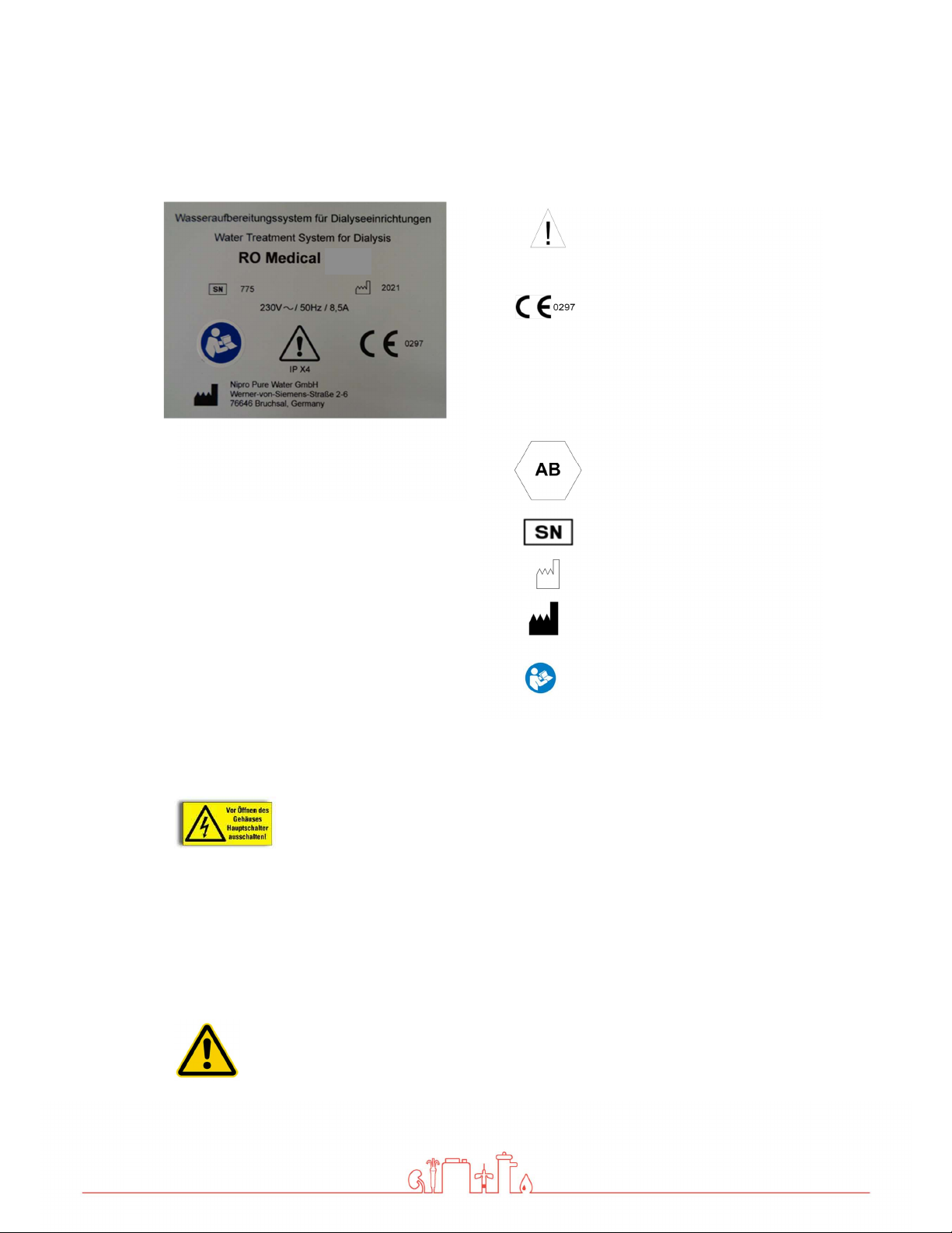
1.7 Model Plate
Version 12| 06.10.2021 | Page 8
IPX 4
Manufacturer
Attention, take note of
accompanying documents
CE mark with the number of
the notified body. Here DQS
Protection against the
ingress of liquids. Here
splash-water protection
Protection Scheme according
to EN 1717. Here free outlet
Serial number
Year of construction
Pay attention to manual
1.8 Warning on the Unit.
Caution voltage. Turn mains switch off before opening housing. Fixed on
control cabinet.
1.9 Shutdown
If a unit is shutdown for more than 5 days, conservation will be necessary.
Please contact Nipro Pure Water before performing conservation.
Page 9

Version 12| 06.10.2021 | Page 9
1.10 Disposal
Regarding the WEEE guidelines of the European Union, the disposal of electronic devices and
electronic sub-assemblies and parts into the general garbage is not lawful. These parts must be
disposed environmentally appropriate:
If not appointed otherwise and no private disposal management is available, these devices or
possibly other environmental hazardous items can be sent back.
The filters and membrane can be disposed via the general garbage
1.11 Instruction / Further Documentation
The using personnel must be warned against the hazards during operation and must be warned
against the hazards of misusing the product.
The personnel gets the instruction of operation and the specialties of usage. Instructed adult only
are allowed to operate this device.
This instruction by the manufacturer or authorized personnel takes place during the
commissioning of the device.
Further trainings are not necessary for this device.
For qualified personnel the following documents can be made available upon request.
Circuit diagrams
Spare parts list
1.12 Duration of usage
The device is designed for a use of 10 years
Page 10
Version 12| 06.10.2021 | Page 10
Serious soiling
2 Intended operation
The unit is designed for the treatment of potable water. The pure water (permeate) thus
produced may be used for dialysis treatment.
Other applications are only possible after consulting the manufacturer and receiving their
approval.
The unit can only be maintained by the manufacturer or technicians trained by
the manufacturer.
Only original replacement parts may be used for maintenance and repairs.
Installation operations, modifications or reparations, are only allowed to be
performed by persons authorised by the manufacturer and may only be done with
original replacement parts. Improper performed reparations or modifications can
lead to hazards to the user and/or may damage the device.
The device may only be operated in perfect condition.
Before operating, check the following:
Lose or defect parts
Defect cables and/or isolations
The device may only be operated with the appropriate ring line.
The device does not produce water for injections.
The device has pressurized parts.
If the temperature sensor fails, the temperature in the permeate can increase.
(Max 60°C)
The water treatment system RO medical may only be used for permeate supply
of dialysis devices, which have a temperature measurement (permeate
temperature).
The device has no direct patient contact and no patient application part.
Page 11

Version 12| 06.10.2021 | Page 11
2.1 Contraindications / side effects
None
3 Safety
3.1 Risk Assessment
There will be no dangers associated with the reverse osmosis model RO medical D if the
operating instructions are followed.
The device can automatically start by way of an auto-start.
3.2 EMC
The device was developed and tested in accordance with current standards. Nevertheless,
influence through electromagnetic fields cannot be completely excluded.
3.3 Emissions
The device does not produce dust or vibrations.
The noise level is under 609 dB (A).
Page 12

4 Technical Data
Temperature
1 Membrane
2 Membranes
3 Membranes
4 Membranes
15° C
350 l/h
700 l/h
1050 l/h
1400 l/h
Quality
Potable Water
Hardness
< 1 °dH
Silicate
< 25 mg/l
Chlorine
< 0,1 ppm (mg/l)
Iron < 0,1 ppm (mg/l)
Fouling Index (S.D.I)
< 3 Temperature
5-25°C Pressure
1-
3 bar
Water feed
1”
internal thread
Pure water connection
Hose nozzle d20
Drain
HT 4
0
Supply voltage
220-230 V, 1 Phase,
50/60 Hz
Fuse
Automat 16 A
-K,
Fi ΔI 30mA
Current consumption
9,9 A
x 60 Hz
Degree of pollution
1
Storage / transport
3-
40°C
Operation
10-
35°C
Air pressure
795-1062 hPa
Conductivity
0-
1000 µS/cm ±5%
100-1000 l/h
RO Medical
1000x500x1
64
0
Permeate performance
Inlet water
Version 12| 06.10.2021 | Page 12
Connections
Electrical data
Ambient temperature
Display system
pressure switch 0-10 bar ±5%
Flow (sight glass) 300-3000 l/h ±5%
Size
Page 13
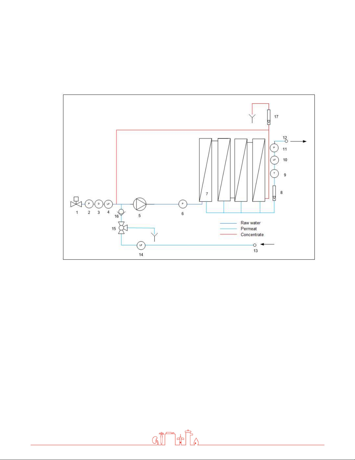
5 Description of the device
5.1 Flow-Chart
Version 12| 06.10.2021 | Page 13
1. Magnetic valve inlet
2. Pressure switch input
3. Disinfection point
4. Conductivity input
5. Pump (pressure 10-13bar)
6. Manometer (pressure 10-13 bar)
7. Reverse osmosis membrane (1-4
pieces)
8. Permeate flow rate indicator
9. Temperature sensor
10. Conductivity probe permeate flow
11. Permeate pressure switch
12. Connection back flow hose nozzle d20
13. Connection back flow hose nozzle d20
14. Conductivity ring back flow
15. Discard three-way ball valve permeate
16. Check valve
17. Flow indicator concentrate outflow
Page 14

Version 12| 06.10.2021 | Page 14
5.2 Functional sequence
If the toggle switch is turned to the ‘On‘ position, the magnetic valve (1) opens and water flows
into the system. After a short delay, the pump (4) will start.
Now the water is pressed into the reverse osmosis membrane at a pressure of 10-15 bar. The
flow is divided into a permeate and a concentrate part. The permeate content flows through the
flow indicator (7), the temperature sensor (8), the conductivity probe (9) and the pressure switch
(10) into the ring line. The unused permeate flows back into the RO medical via the connection
(12).
To save water, the concentrate portion is divided up again, one portion is given into the drain via
the flow indicator (17), the other is fed back in front of the pump.
Page 15
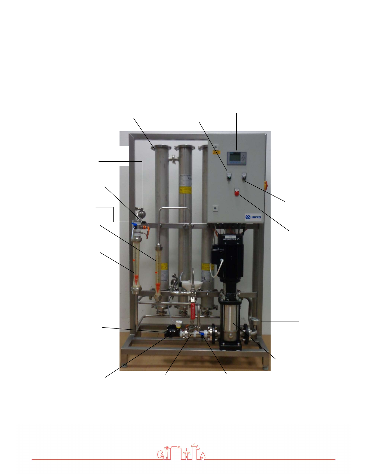
5.3 Safety devices / Components
Inlet
Mode switch
Connection
Turn on key
Pressure switch
Permeat Flow
Pressure Switch
Inlet
Pressure tube with
membrane
Version 12| 06.10.2021 | Page 15
Display
Main switch
Service Point
Flow Display
Concentrate
Flow Display
Permeat
Raw water
connection
Magnetic valve
Conductivity Probe
Inlet
Disinfection port
Emergency
Fault signal lamp
Manometer
Pump pressure
Pressure pump
Page 16

6 Installation
The installation must be conducted by the manufacturer or by personnel trained
and authorized by the manufacturer.
6.1 Environmental Condition
Conditions for the osmosis room:
Relative air moisture < 90% at 20°C
Room temperature between +10°C and +35°C (frost proof)
Equipped with floor drain, water supply and electrical supply
Version 12| 06.10.2021 | Page 16
6.2 Assembly
Bring the device into the appropriate position
Adjust machine feet until the device stands level and secure on the floor.
Do not store easily flammable materials in the vicinity of the device.
Do not store chemicals in the vicinity of the device.
Only operate the device with the necessary water pre-treatment.
Room of osmosis may not be freely accessible. (Access for instructed personnel
only)
Page 17

6.3 Electrical installation
The installation may only be performed by a qualified electrician.
The device must be supplied by a permanent connection, connectors are not
valid. The disconnection via the main switch at the control cabinet. The power
cord must be provided with a strain relief.
Version 12| 06.10.2021 | Page 17
Connection cable RO Medical
For protection against a re-start of the unit, the main switch
can be locked with a padlock.
Safety class I
The device is equipped with a Protective earth terminal for
prevention against high touch current
For prevention of the hazard of an electric shock, this device
may only be connected to a power supply with protective
earth.
The power cord is fixed to the device and cannot be replaced.
Page 18

6.4 Prefiltration (Example)
Install the necessary water pre-treatment equipment first!
Only then connect the RO medical and start up
Version 12| 06.10.2021 | Page 18
Local water works regulations and DIN EN 1717 must be followed.
The water pre-treatment must be adapted to the local potable water quality.
Page 19

6.5 Commissioning
filter and a softening system
HT 40
Hose nozzle d20
Caution, device damage!
The device must be preconnected by a suitable preas well as a pressure reducer.
Permeat Flow Connection (2)
Hose nozzle d20
Version 12| 06.10.2021 | Page 19
Permeat back flow (3)
Drain water
connection (4)
Raw water connection (1)
1“ Internal thread
Page 20

Version 12| 06.10.2021 | Page 20
water (4)
Now water is running into
the device
.
water outlet can be seen.
6.6 Initial commissioning
1. Connect and check the raw water connection (1),
permeate flow (2), permeate back flow (3) and waste
2. Open the inlet valve manually. To do this, turn the white
magnet coil 45° counter clockwise.
3. Carefully open the screw for the pump venting until a
Then close the screw again and
reset the solenoid.
4. Make sure that the wall-mounted taps at the start and end
of the ring are open.
5.
Start the device using the toggle switch.
6.
Check all connections for leaks.
7.
Open the three-way valve permeate to the drain.
8.
Allow the device to discard permeate for at least 30
minutes.
Page 21

7 Operation
and off
emergency operation here.
operation (4)
Toggle switch (1)
Fault light (2)
Display (3)
Version 12| 06.10.2021 | Page 21
7.1 Control Panel
Right Side
Main Switch (5)
Key switch
emergency
1. Toggle switch system on
This is used to switch the device on
4. Key switch emergency operation
The device can be switched to
Page 22

Version 12| 06.10.2021 | Page 22
completely
2. Fault light
Lights up when there is a fault
3. Display
Display of conductivity and faults
5. Main switch
With this the device can be switched off
7.2 System on / off without permeate tank
System on
To start the device, turn the toggle switch to the right (on
position).
The green lamp lights up.
The pump starts after a short delay
System off
Reset toggle switch (position 0)
The green lamp goes out.
Pump stops.
If the device is switched off using the toggle switch, the rinse intervals are
carried out as programmed. If no rinsing is to take place, the device must be
switched off completely at the main switch. However, this is only
recommended for decommissioning.
Page 23

7.3 Device on / off with permeate tank
is connected to a permeate tank, the toggle switch must be
full, it is not necessary to reset it to position 0.
If the tank is already full, the osmosis waits to start until the level
If the RO medical
set to "Auto". Since the device switches off automatically when the tank is
Caution, danger of overflow!
If the RO medical is operated with a permeate tank, the system may only be
started via "Auto". In the "On" position there is a risk of overflow.
Device on
To start the system, turn the knob switch to the right.
If the permeate tank is empty, the system starts automatically.
Version 12| 06.10.2021 | Page 23
in the tank drops.
Page 24

7.4 Emergency operation
Caution!
If the HC Medical hot cleaning system is connected, the following steps
must be carried out before emergency operation:
1. Check HC Medical for pending alarms.
2. Carefully touch the lines of the HC Medical and check whether
they are warm.
Do not carry out emergency operation when the lines are warm !!
Only use emergency operation if the automatic function fails. Have device
repaired as soon as possible.
Version 12| 06.10.2021 | Page 24
Attention!
There is no monitoring of the water inflow during the emergency operation.
Therefore a continuous water inflow has to be guaranteed.
Absent water causes the destruction of the pump.
1. Open the inlet valve manually. To do this, turn the white
magnet coil 45° counter clockwise.
To turn off the device, turn switch to position 0.
Now water runs into the device.
2. Set the key switch to position 1. Pump starts up
In emergency operation all automatic functions are turned off. No cleaning cycle
and no automatic start and/or stop will be conducted.
Page 25

7.5 Operating displays
System Off
Set: 90:00
Actual: 25:22
Until rinsing
Device is off.
Rinsing interval (target) is set to 90 minutes.
25:22 min have already passed.
If the actual value reaches the set point, the system goes into rinsing.
Version 12| 06.10.2021 | Page 25
System On
LF Flow 008
LF Backflow 008
Microsiemens
Rinsing
LF Flow 008
LF Backflow 008
Microsiemens
Device is on.
The current conductivities are displayed.
Device is being rinsed.
The current conductivity is displayed.
Page 26

8 Error messages / troubleshooting
The temperature of the permeate has reached
Check the start and end of the
Call service.
8.1 Error messages
Display
Error
Motor protection triggered
Check 1Q5
Error
Over temperature
Check 16S12
Error
Over pressure
Check 16S08
Error
Inlet water missing
Check 16S6
Error
Conductivity
Error Description
The motor protection switch of the pump has
triggered. Check motor protection switch. If
this alarm occurs frequently, the pump must
be checked.
to 38 °C. The system switches off to protect
the membranes.
The permeate pressure has exceeded 6 bar.
The pressure switch 1 has responded.
The conductivity has exceeded the limit of
100µS/cm.
Version 12| 06.10.2021 | Page 26
Troubleshooting
Turn the motor protection
switch back to position 1.
The system must be cooled
(see next page).
ring taps. Check setting of
permeate pressure retention
valve.
Check water inlet.
There is probably a defect in
the membranes.
8.2 Clear alarms
Correct the error
Follow the notes in Display.
Clear the alarm by pressing the F3 key
Page 27

Version 12| 06.10.2021 | Page 27
9 Maintenance and cleaning
9.1 External Cleaning
Stains and dust can be removed with a cloth and a commercially available cleaner.
Do not clean the device with solvents.
Stains from softening salts or disinfectants must be removed immediately.
Page 28

Version 12| 06.10.2021 | Page 28
Measure
period
Notes
user
9.2 Maintenance Intervals
Fill salt at softener Daily user
Chemical disinfection If needed Manufacturer or
persons authorized by
manufacturer
Maintenance Yearly Manufacturer or
persons authorized by
manufacturer
Safety related check Every 2 years Manufacturer or
persons authorized by
manufacturer
Microbiological analysis Every 3 months User
Chemical analysis
Every 12 months User
Not replacing the filter or replacing it too late can lead to damaging of the reverse
osmosis.
Page 29

9.3 Chemical Disinfection
high pathogen values are encountered
guidelines
before handling.
A chemical disinfection should only be performed upon new installation or when
Disinfection may only be performed by Nipro Pure Water or by instructed
persons.
Caution when handling disinfectants!
Per acetic acids can cause damage to your health. Always read safety
Before the next dialysis each consumption point must be tested for disinfectant
traces.
Version 12| 06.10.2021 | Page 29
Page 30

Version 12| 06.10.2021 | Page 30
9.4 Microbiological Inspection
Necessary Values1
Pathogens < 100 CFU/ml no traces of Pseud. aeruginosa and E. coli
Endotoxins < 0,25 EU/ml
Inspection Interval 2
Inspection of permeate every 3 months.
Inspection method 2
Pathogen count determination:
Nutrient medium: TGEA (OXID Nr.CM 127), R2A
Incubation temperature: 22°C ± 2°C
Endotoxins determination:
Method: GEL-Clot; Cromogen; Turbid metric
_________________________
1
According to the European Pharmacopoeia
² Recommendations according to the guideline for the practice of applied hygiene in treatment units for dialysis
Page 31

Version 12| 06.10.2021 | Page 31
back to the
The X indicates which key can be used to switch back to the
If the key is pressed again, the display changes back to the
10 Display / Parameter
10.1 Retrieval of the operating hours / conductivities
Press the F1 key. The operating hours are displayed.
If the key is pressed again, the display changes
standard display.
X
standard display.
Press the F2 key. The conductivities are displayed.
standard display.
To view the time and date, press the down arrow.
Page 32

10.2 Change the conductivity parameter
Press the F4 key and F2 key simultaneously.
The conductivity in the return is displayed.
Press the ESC key for 3 seconds, the first value is marked.
Press enter
Set the value with the arrow keys (up / down). Complete the
entry with ENTER.
Press the ESC key.
Press the F4 and F2 keys simultaneously to return to the
standard display
Both parameters (MAX1 and MAX2) must be set to the same value.
Version 12| 06.10.2021 | Page 32
Standard value = 100 µS / cm
If the conductivity in the back flow reaches the value set here, the conductivity
alarm is activated.
Page 33

10.3 Change parameter temperature
M
ax. 40°C
is allowed,
higher temperatures damage the membranes
.
Press the F4 key and F3 key simultaneously.
The temperature is displayed.
Press the ESC key for 3 seconds, the first value is marked.
Select corresponding value with the arrow keys.
Press enter
Set the value with the arrow keys (up / down). Complete the
entry with ENTER.
Press the ESC key.
Press the F4 and F3 keys simultaneously to return to the
standard display
Version 12| 06.10.2021 | Page 33
Both parameters (MAX1 and MAX2) must be set to the same value.
Default value = 38°C
If the temperature reaches the value set here, the over temperature alarm is
activated.
CAUTION!
Page 34

Version 12| 06.10.2021 | Page 34
Technical appendix
The settings and functions described below may only be carried out by technically
trained personnel.
ATTENTION. DANGER TO PERSONS AND SYSTEM TECHNOLOGY!
Incorrect settings can lead to hazards.
No service or maintenance work may be carried out during treatment.
Page 35

Version 12| 06.10.2021 | Page 35
1.
Switch off the system at the main switch
.
11 Replacement of the reverse osmosis
membrane
Caution pressure!
Membrane tubes are under pressure. Please open carefully.
The settings and functions described below may only be carried out by technically
trained personnel.
2. Open wing screw and take off the clip
3. Lift module cover by using a screwdriver.
4. Take off cover.
5. Take the end plug out of the module.
6. Pull out the membrane by using a tong.
7. Reinstall the new membrane in reverse order.
Take care of the flow direction and
position of the gasket
Page 36

Rinse membrane!
B001
3sec
B002
60m
B003
10m
B005
5sec
B019
30sec
B034
30sec
B036
B040
After the new membrane has been installed the mode “drain permeate”
has to be started for 20 minutes.
12 Service Parameters
The settings and functions described below may only be carried out by technically
trained personnel.
ATTENTION, SYSTEM DAMAGE!
Incorrect settings can lead to damage.
Version 12| 06.10.2021 | Page 36
Arrow key down and then press the ESC key. (Service mode)
Then Logo settings> ENTER> Program> ENTER> Set
parameters> ENTER> select the appropriate parameter (B001-
Parameter Function
B021
B037
B040)
Pump start time delay
Rinse waiting time
Rinse time
Dry flow alarm delay
Conductivity alarm delay
Adjustment of conductivity
(permeate)
Alarm delay temperature
Calibration of conductivity (inflow)
Adjustment of conductivity
(permeate back flow)
Timer (auto start)
default value
Page 37

12.1 Adjustment of the conductivity
saving time (summertime) in the
- Call up parameters B21, B36 or B37.
- "Ax" value = displayed conductivity
- Select value "B" and confirm with Enter.
- Change the value with the arrow keys. (+00001 = current value +1)
- press enter
- Press ESC several times (until time is displayed), then arrow key up.
12.2 Setting date and time
Version 12| 06.10.2021 | Page 37
- Call up service mode
- LOGO Settings <ENTER> Setup <ENTER> Clock <ENTER> Set Clock <ENTER>
- Set the time and date with the arrow keys <ENTER
12.3 Summer / winter time
- Call up service mode
- Setup <ENTER> Clock<ENTER>S/W Time – Select the S/W Time
– "④": disables automatic S/W time conversion.
– "⑤" represents the start and end of European summertime.
– "⑥" represents the start and end of summertime in the United Kingdom.
– "⑦" represents the start and end of daylightUnited States prior to 2007.
– "⑧" represents the start and end of daylight-saving time (summertime) in the
United States in 2007 and later years.
– "⑨" represents the start and end of Australian summertime.
– "⑩" represents the start and end of Australian/ Tasmanian summertime.
– "⑪" represents the start and end of New Zealand summertime.
– "⑫": Here you can enter any month, day and time zone difference.
Page 38

Version 12| 06.10.2021 | Page 38
-Press right arrow key to move the cursor to the first position of the
Press right arrow key to move the cursor to the first position of the
12.4 Auto Start (Timer)
Call up service mode
Logo settings < ENTER > Program < ENTER > Set parameters
< ENTER > Select parameter B040<ENTER>
To set the on-/off-times:
-Move the cursor to one of the parameters of the timer.
-Press ENTER. The cursor is positioned on the day of the week.
-Press up and down key to select one or several days of the week.
on-time.
-Set the on-time.
Modify the value at the respective position, using the up and down
keys and move to the cursor to the various positions, using the
right and left arrow keys.
At the first position, you can only select the value - -:- - (- -:- means: No on-/off-times set).
off-time.
-Set the off-time
-Confirm your entries with ENTER
The prefix "D=" (Day) has the following meaning:
Thursday
● F: Friday ● S: Saturday ● S: Sunday
Uppercase letters indicate a specific day of the week. A "-" indicates no selection for the day of the week.
● M: Monday ● T: Tuesday ● W: Wednesday ● T:
Page 39

Version 12| 06.10.2021 | Page 39
only be operated by
technically trained personnel
.
12.5 Service point
The service point can be used for water withdrawal to check water temperature and conductivity.
Service point may only be opened, if operating pressure in the system is
reached.
Service point must be closed prior to each system start. Service point may
Page 40

13 Disinfection
Disinfection may only be performed by Nipro Pure Water or by instructed
persons.
Caution when handling disinfectants!
Per acetic acids can cause damage to your health. Always read safety
guidelines before handling.
To be performed precisely!
Danger!
Ensure that no dialysis can be performed while disinfecting. Only approve
thoroughly rinsed system for treatment use.
CAUTION!
While using chemicals.
Wear safety gloves and safety goggles during the
here described jobs.
Version 12| 06.10.2021 | Page 40
ATTENTION!
Do not eat, drink or smoke during work.
Disinfectant: MINNCARE® Cold Sterilant (Artikelnr.:489)
Detection method: MINNCARE® Test Strips Residual (Artikelnr.:490)
MINNCARE® Test Strips 1 Indication (Artikelnr.:491)
Page 41

Version 12| 06.10.2021 | Page 41
2.
8.
1. Connect the disinfection pump to the disinfection point.
3.
4.
5.
6.
7.
Open the three-way valve permeate to the drain.
Start the device
Start the disinfectant pump.
Check for correct disinfectant concentration at the
permeate outlet with test strips. Use Minncare Test Strips
Indication 1% for this.
Let the disinfectant pump run until sufficient disinfectant is
detected.
Close the three-way valve permeate to the drain.
Switch off the system
9.
Restart the system after 20 minutes.
Page 42

Version 12| 06.10.2021 | Page 42
13.
that it is free from disinfectants.
10.
11.
12.
Open the three-way valve permeate to the drain.
Let the system run until no more disinfectant can be
detected at the permeate drain. Use Minncare residual
test strips for this.
Close the three-way valve permeate to the drain.
Check that all dialysis stations are free from disinfectants.
Switches the system off during disinfection with a conductivity alarm,
clear the alarm and restart the system.
RISK OF DEATH !
Before the next dialysis, each sampling point must be tested again to ensure
* Free of disinfection means 0ppm- no discoloration of the test strip.
See the colour scale on the packaging of the test strip Residual.
Page 43

13.1 Disinfection Protocol
Disinfectant type
Inoculated amount in litres
Wash time in minutes
Wait time in minutes
stations and results were negative?
disinfectant
Date
Signature
Dialysis centre
Section
Contact person
Function
Street / Bldg. No.
Postcode / City
Unit model : RO Medical
Serial number:
Ring line length
Version 12| 06.10.2021 | Page 43
Rinse time in minutes
If disinfection was performed the operator is obligated by its signature to re-test all dialysis stations
for
. This test must be conducted before the dialyses are performed
______________________
Tested for disinfectant at all dialysis
yes
____________________________
Page 44

Version 12| 06.10.2021 | Page 44
Voltage fluctuations / flickers in
14 EMC manufacturer's declaration
Electromagnetic emissions and electromagnetic immunity
The RO device is intended for use in electromagnetic environments as described below.
The customer or the operator of the RO should ensure that the device is only used in such an
environment.
This EMC manufacturer's declaration is based on the use of the power supply unit from Phoenix
Contact.
The power supply is installed in the control cabinet.
The cable length between the power supply unit and the cable entry through the housing wall is
150 cm.
Warning
The use of other accessories, other power supply units and cables than specified can lead to
increased emissions and/or reduced interference immunity of the RO.
Requirements
During the interference immunity tests, the temperature accuracy and conductivity accuracy
were checked.
Emission measurement Compliance
RF emission in accordance with
CISPR 11 / EN 5511
RF emission in accordance with
CISPR 11 / EN 55011
Harmonics in accordance with
IEC 61000-3-2
accordance with IEC 61000-3-3
Group 1 The device only uses RF
Class B The device is suitable for use
Class A
Fulfilled
Electromagnetic
environment - Guidelines
energy for its internal
function. Its RF emissions are
therefore very low and
interference to nearby
electronic devices is unlikely.
at any location, including
residential areas and facilities
directly connected to the
public low-voltage grid for
residential buildings.
Page 45

Immunity test
Discharge of
static electricity
(ESD) in
accordance with
EIC 61000-4-2
Electrical fast
transient
burst/immunity
test in
accordance with
IEC 61000-4-4
Surge voltage in
accordance with
IEC 61000-4-5
Voltage drops,
short
interruptions,
and fluctuations
in supply voltage
in accordance
with IEC 610004-11
Magnetic field at
supply frequency
(50/60 Hz)
in accordance
with IEC 610004-8
Conducted RF
disturbances in
accordance with
IEC 61000-4-6
Radiated RF
disturbances in
accordance with
IEC 61000-4-3
Version 12| 06.10.2021 | Page 45
Test level – IEC
60601
± 6 kV contact
discharge
± 8 kV air
discharge
Compliance
level
± 6 kV contact
discharge
± 8 kV air
discharge
Electromagnetic
environment - Guidelines
The floor should be made of
wood, concrete, or of tiles. In
case of synthetic flooring,
relative air humidity should be
at least 30%.
± 2 kV for power
cables
± 1 kV for input
and output cables
± 1 kV outer
conductor-outer
conductor
± 2 kV outer
conductor-ground
95% voltage drop
for ½ period
60% voltage drop
for 5 periods
30% voltage drop
for 25 periods
95% voltage drop
for 5 s
± 2 kV for power
cables
± 1 kV for input
and output cables
± 1 kV outer
conductor-outer
conductor
± 2 kV outer
conductor-ground
95% voltage drop
for ½ period
60% voltage drop
for 5 periods
30% voltage drop
for 25 periods
95% voltage drop
for 5 s
The quality of supply voltage
should comply with that of a
typical commercial or hospital
environment.
The quality of supply voltage
should comply with that of a
typical commercial or hospital
environment.
The quality of supply voltage
should comply with that of a
typical commercial or hospital
environment. If the device is
to continue functioning
uninterruptedly in case of
power interruptions, it is
recommended that the device
be operated via uninterrupted
power supply or a battery.
3 A/m 3 A/m In supply frequency, the
magnetic fields should comply
with the values characteristic
of locations in a typical
commercial or hospital
environment.
3 V rms
150 kHz to 80
MHz
3 V rms
150 kHz to 80
MHz
When operating portable or
mobile RF communication
devices (transmitters), a
safety distance should be
observed to all parts of the
device, including cables,
calculated on the basis of one
of the following equations
depending on the transmission
frequency.
Recommended safety
distance:
3 V/m
80 MHz to 2.5
GHz
3 V/m
80 MHz to 2.5
GHz
d = 1.2P 150 kHz to 80 MHz
d = 1.2P 80 MHz to 800
MHz
Page 46

Version 12| 06.10.2021 | Page 46
he
d = 2.3P 800 MHz to 2.5
GHz
Whereby P is the maximum
nominal output of the
respective transmitter
specified by the manufacturer
in Watts (W), and d is the
recommended safety distance
in meters (m).
The field strength of
stationary RF transmitters,
which is definable via
electromagnetic site survey a,
should be below the
compliance level of the
individual frequency ranges b.
Disturbances are possible near
devices which bear the symbol
below.
Note: These guide values may not apply to all situations. Spreading of electromagnetic
waves is also influenced by absorption and reflection via buildings, items, persons, and
animals.
a. The field strength of stationary transmitters (e.g. base stations of mobile phones
(mobile/cordless) and mobile land mobile radios, amateur radio stations, AM and FM
radio, and TV transmitters), cannot be theoretically calculated in advance. To identify
the electromagnetic environment with regard to stationary RF transmitters, an
electromagnetic site survey should be considered. If the field strength identified at the
location at which the device is used exceeds the RF compliance level specified above, t
device should be closely observed. It may be necessary to take additional measures
(e.g. changing the alignment or transposition of the device).
b. Across the frequency range of 150 kHz to 80 MHz, the field strength should be less
than 3 V/m.
Page 47

Version 12| 06.10.2021 | Page 47
Recommended minimum distances between portable and
mobile RF communication devices and the RO
The RO is intended for use in electromagnetic environments in which radiated RF disturbances are
controlled. The buyer or user of the RO can help prevent electromagnetic interference by maintaining a
minimum distance between portable/mobile RF communications equipment (transmitters) and the RO as
recommended below, according to the maximum output power of the communications equipment
Max. output of the
transmitter
(W)
0.01 0.12 0.12 0.23
0.1 0.38 0.38 0.73
1 1.2 1.2 2.3
10 3.8 3.8 7.3
100 12 12 23
For transmitters with a maximum output not specified above, the recommended
distance d in meters (m) can be calculated in accordance with the equation appropriate
for the frequency of the transmitter, whereby P is the maximum output of the
transmitter in Watts (W) in accordance with the specifications of the manufacturer.
NOTE 1:
For 80 MHz and 800 MHz, the safety distance applies for the higher frequency range.
NOTE 2:
These guide values may not apply to all situations. Spreading of electromagnetic waves
is also influenced by absorption and reflection via buildings, items, and persons.
Minimum distance in accordance with the frequency of the
transmitter (m)
150 kHz to 80 MHz
d=1.2 √P
80 MHz to 800 MHz
d=1.2 √P
800 MHz to 2.5 GHz
d=2.3 √P
 Loading...