NIPRO DIAMAX User manual

4.6 (36)

MAINTENANCE MANUAL

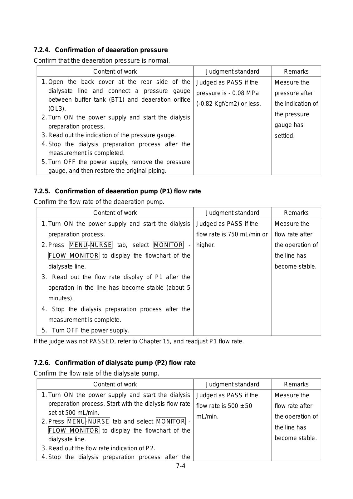
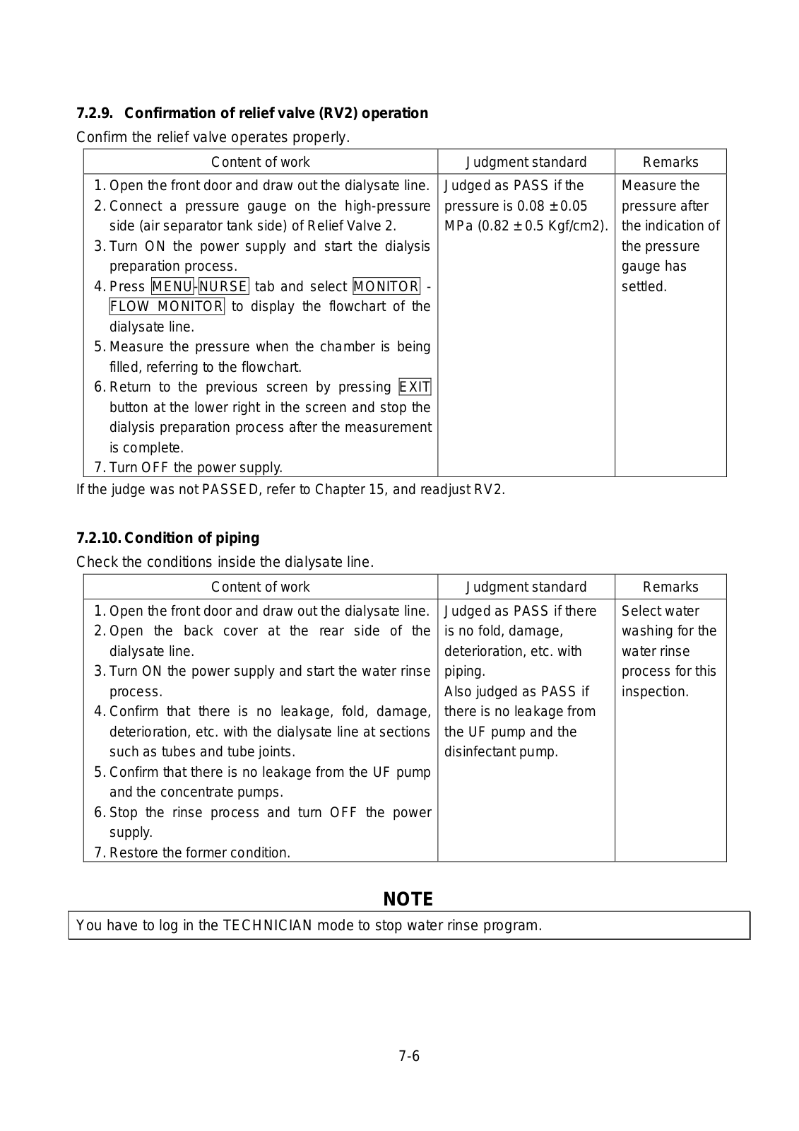
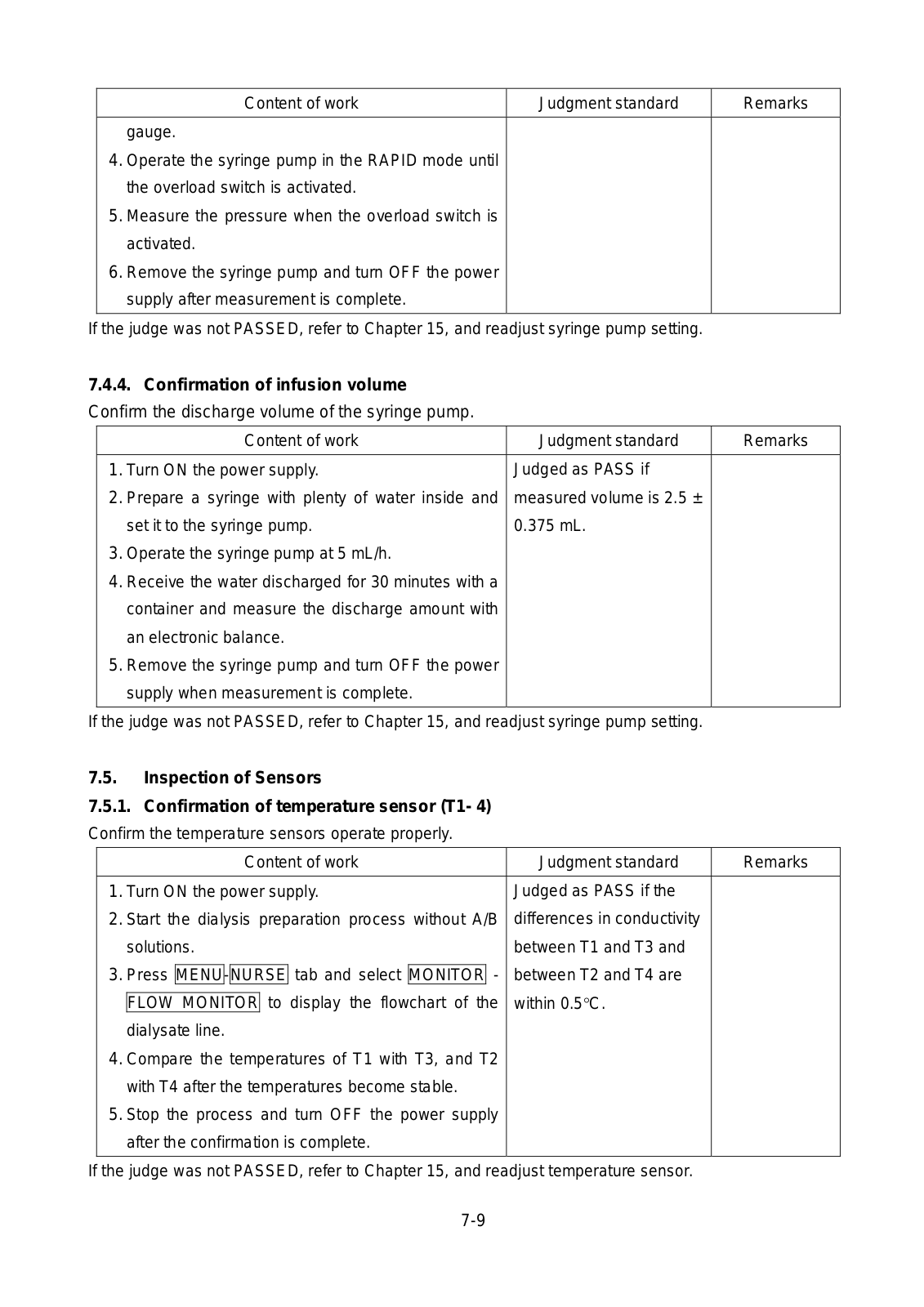
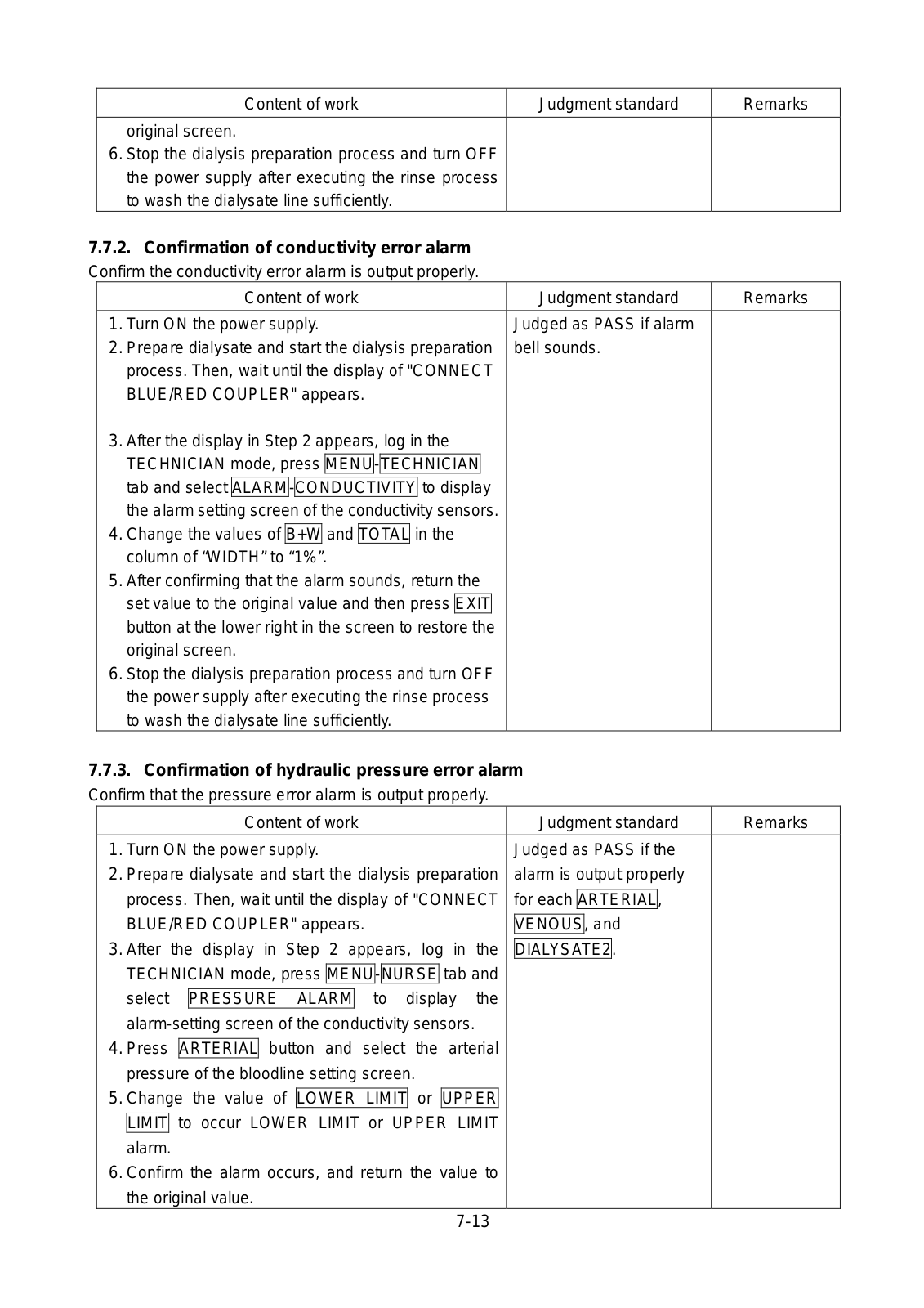
SINGLE PATIENT DIALYSIS MACHINE

DIAMAX

NIPRO CORPORATION

3-9-3 HONJO-NISHI, KITA-KU, OSAKA, JAPAN Phone +81-6-6372-2331

NIPRO EUROPE N.V.

WEIHOEK 3H-1930 ZAVENTEM, BELGIUM

Phone +32-2-725-5533

MX2005-0703E1

TABLE OF CONTENTS

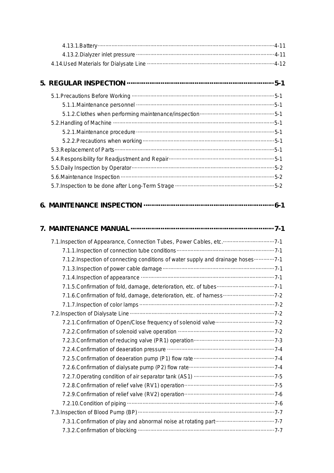
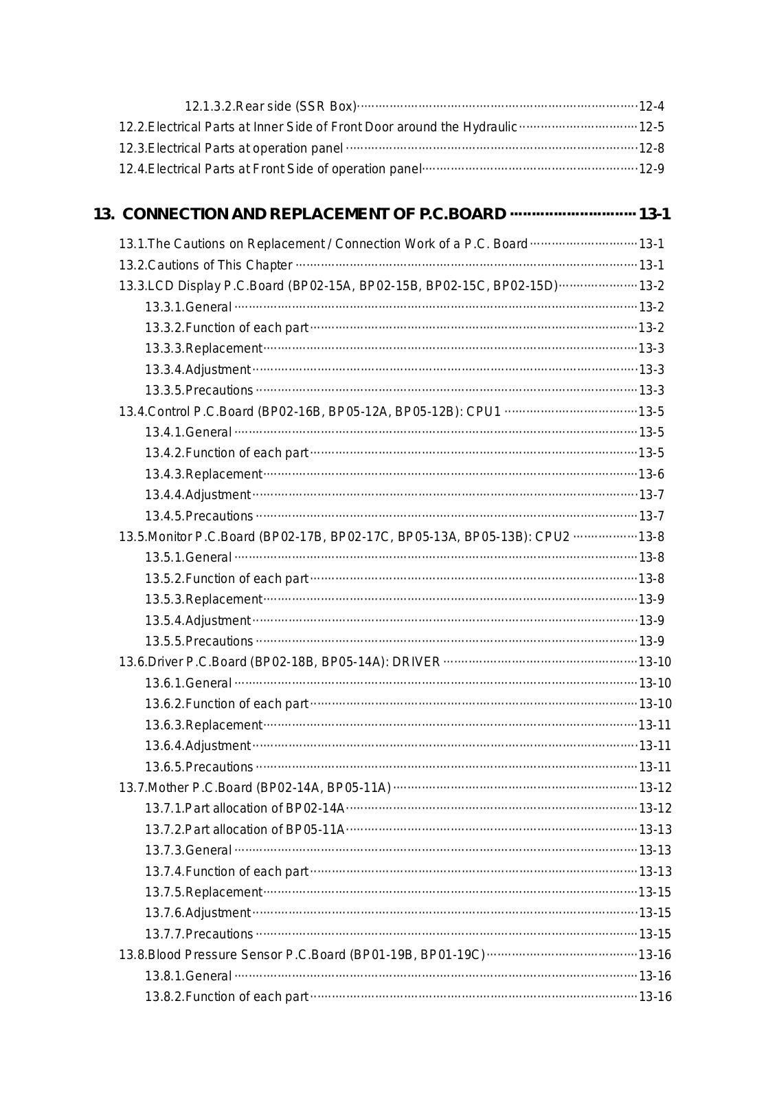
1.APPLICATION·······························································································1-1

2.CONTRAINDICATION···················································································2-1

3.PRECAUTIONS·····························································································3-1

3.1.Equipment Classification and Handling precautions························································3-1 3.2.Precaution for Fluid Penetration·······················································································3-1 3.3.Precaution for Flammable Atmospheres··········································································3-1 3.4.Safety Precautions ···········································································································3-1 3.5.Precautions ······················································································································3-5 3.6.Precautions for Software··································································································3-8

4. GENERAL DESCRIPTION············································································4-1

4.1.Dimensions and Weight ···································································································4-1 4.2.Electrical Safety (Ordered by EN60601-1) ·····································································4-1 4.3.Electrical Supply···············································································································4-2 4.4.Fuses································································································································4-2 4.5.External Connections ·······································································································4-2 4.6.Storage and Transportation ·····························································································4-2 4.7.Operating Conditions ·······································································································4-3 4.8.Hydraulics·························································································································4-4

4.8.1.Blood leak detector ································································································4-4 4.8.2.Transmembrane pressure ·····················································································4-4 4.8.3.Dialysate pressure ·································································································4-4 4.8.4.Ultrafiltration···········································································································4-5 4.8.5.Degassing ··············································································································4-5 4.8.6.Acetate dialysis······································································································4-5 4.8.7.Bicarbonate dialysis·······························································································4-6 4.8.8.Dialysate temperature····························································································4-6 4.8.9.Dialysate flow rate··································································································4-6

4.9.Extra Corporeal Blood Circuit···························································································4-7 4.9.1.Arterial pressure·····································································································4-7 4.9.2.Venous pressure····································································································4-7 4.9.3.Air Detector ············································································································4-7 4.9.4.Blood pump············································································································4-8 4.9.5.Syringe pump·········································································································4-9 4.9.6.Single needle single pump·····················································································4-9

4.10.Rinse ······························································································································4-10 4.11.Override··························································································································4-10 4.12.Range of Sound Pressure Levels ··················································································4-10 4.13.Options···························································································································4-11

4.13.1.Battery··················································································································4-11 4.13.2.Dialyzer inlet pressure ·························································································4-11 4.14.Used Materials for Dialysate Line ··················································································4-12

5. REGULAR INSPECTION ··············································································5-1

5.1.Precautions Before Working ····························································································5-1 5.1.1.Maintenance personnel ·························································································5-1 5.1.2.Clothes when performing maintenance/inspection················································5-1 5.2.Handling of Machine ········································································································5-1 5.2.1.Maintenance procedure ·························································································5-1 5.2.2.Precautions when working·····················································································5-1 5.3.Replacement of Parts·······································································································5-1 5.4.Responsibility for Readjustment and Repair····································································5-1 5.5.Daily Inspection by Operator····························································································5-2 5.6.Maintenance Inspection ···································································································5-2 5.7.Inspection to be done after Long-Term Strage ································································5-2

6.MAINTENANCE INSPECTION ·····································································6-1

7.MAINTENANCE MANUAL············································································7-1

7.1.Inspection of Appearance, Connection Tubes, Power Cables, etc.·································7-1 7.1.1.Inspection of connection tube conditions·······························································7-1 7.1.2.Inspection of connecting conditions of water supply and drainage hoses·············7-1 7.1.3.Inspection of power cable damage········································································7-1 7.1.4.Inspection of appearance ······················································································7-1 7.1.5.Confirmation of fold, damage, deterioration, etc. of tubes·····································7-1 7.1.6.Confirmation of fold, damage, deterioration, etc. of harness·································7-2 7.1.7.Inspection of color lamps ·······················································································7-2

7.2.Inspection of Dialysate Line ·····························································································7-2 7.2.1.Confirmation of Open/Close frequency of solenoid valve······································7-2 7.2.2.Confirmation of solenoid valve operation ······························································7-2 7.2.3.Confirmation of reducing valve (PR1) operation····················································7-3 7.2.4.Confirmation of deaeration pressure ·····································································7-4 7.2.5.Confirmation of deaeration pump (P1) flow rate····················································7-4 7.2.6.Confirmation of dialysate pump (P2) flow rate·······················································7-4 7.2.7.Operating condition of air separator tank (AS1) ····················································7-5 7.2.8.Confirmation of relief valve (RV1) operation··························································7-5 7.2.9.Confirmation of relief valve (RV2) operation··························································7-6 7.2.10.Condition of piping ·······························································································7-6

7.3.Inspection of Blood Pump (BP)························································································7-7 7.3.1.Confirmation of play and abnormal noise at rotating part······································7-7 7.3.2.Confirmation of blocking ························································································7-7

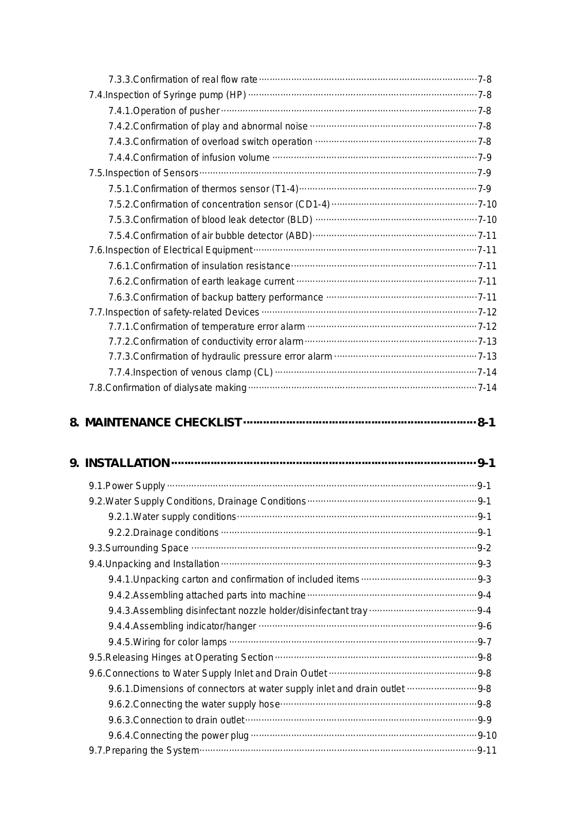
7.3.3.Confirmation of real flow rate·················································································7-8 7.4.Inspection of Syringe pump (HP) ·····················································································7-8 7.4.1.Operation of pusher ·······························································································7-8 7.4.2.Confirmation of play and abnormal noise ······························································7-8 7.4.3.Confirmation of overload switch operation ····························································7-8 7.4.4.Confirmation of infusion volume ············································································7-9 7.5.Inspection of Sensors·······································································································7-9 7.5.1.Confirmation of thermos sensor (T1-4)··································································7-9

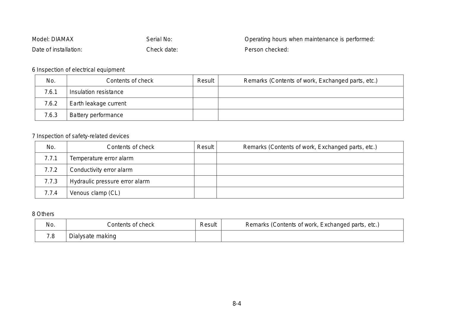
7.5.2.Confirmation of concentration sensor (CD1-4) ······················································7-10 7.5.3.Confirmation of blood leak detector (BLD) ····························································7-10 7.5.4.Confirmation of air bubble detector (ABD)·····························································7-11 7.6.Inspection of Electrical Equipment···················································································7-11 7.6.1.Confirmation of insulation resistance·····································································7-11 7.6.2.Confirmation of earth leakage current ···································································7-11 7.6.3.Confirmation of backup battery performance ························································7-11 7.7.Inspection of safety-related Devices ················································································7-12 7.7.1.Confirmation of temperature error alarm ·······························································7-12 7.7.2.Confirmation of conductivity error alarm································································7-13 7.7.3.Confirmation of hydraulic pressure error alarm ·····················································7-13 7.7.4.Inspection of venous clamp (CL) ···········································································7-14 7.8.Confirmation of dialysate making·····················································································7-14

8.MAINTENANCE CHECKLIST·······································································8-1

9.INSTALLATION·····························································································9-1

9.1.Power Supply ···················································································································9-1 9.2.Water Supply Conditions, Drainage Conditions·······························································9-1 9.2.1.Water supply conditions·························································································9-1 9.2.2.Drainage conditions ·······························································································9-1 9.3.Surrounding Space ··········································································································9-2 9.4.Unpacking and Installation·······························································································9-3 9.4.1.Unpacking carton and confirmation of included items···········································9-3 9.4.2.Assembling attached parts into machine·······························································9-4 9.4.3.Assembling disinfectant nozzle holder/disinfectant tray ········································9-4 9.4.4.Assembling indicator/hanger ·················································································9-6 9.4.5.Wiring for color lamps ····························································································9-7 9.5.Releasing Hinges at Operating Section···········································································9-8 9.6.Connections to Water Supply Inlet and Drain Outlet ·······················································9-8 9.6.1.Dimensions of connectors at water supply inlet and drain outlet ··························9-8 9.6.2.Connecting the water supply hose·········································································9-8 9.6.3.Connection to drain outlet······················································································9-9

9.6.4.Connecting the power plug ····················································································9-10 9.7.Preparing the System·······································································································9-11

9.7.1.Filling water in the hydraulic ··················································································9-11 9.7.2.Setting date and clock ···························································································9-12 9.7.3.Setting a diameter of tube segment in the blood pump·········································9-12 9.7.4.Setting the Syringe pump ······················································································9-13 9.7.5.Setting the dialysate to be used·············································································9-14

9.8.Changing a PASS ID········································································································9-15 9.9.Verifying operation after installation·················································································9-15 9.10.Disposal of Machine·······································································································9-16 9.10.1.Disposal of main machine····················································································9-16 9.10.2.Disposal of LCD display·······················································································9-16 9.10.3.Disposal of backup battery ··················································································9-16

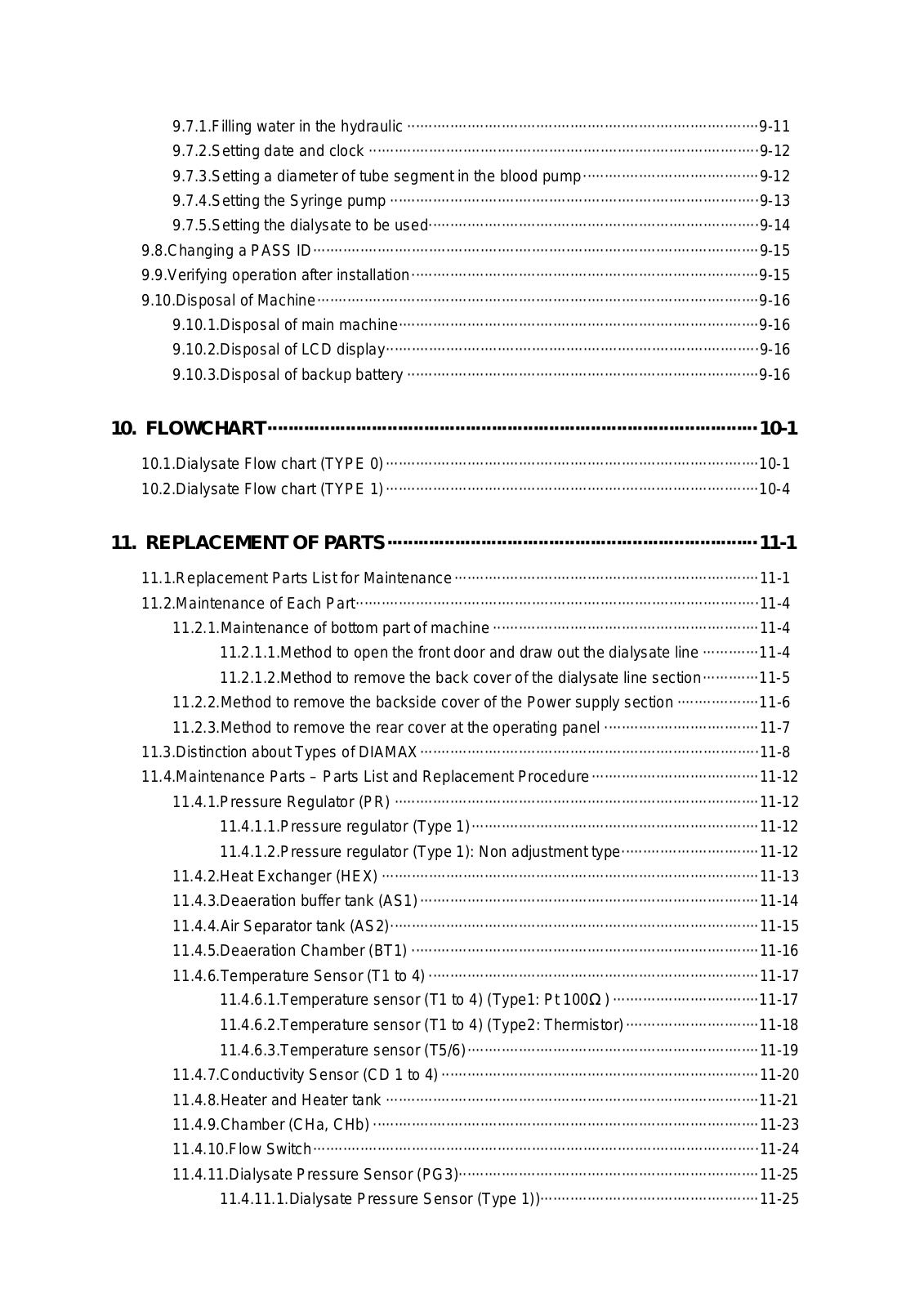
10. FLOWCHART······························································································10-1

10.1.Dialysate Flow chart (TYPE 0)·······················································································10-1 10.2.Dialysate Flow chart (TYPE 1)·······················································································10-4

11. REPLACEMENT OF PARTS·······································································11-1

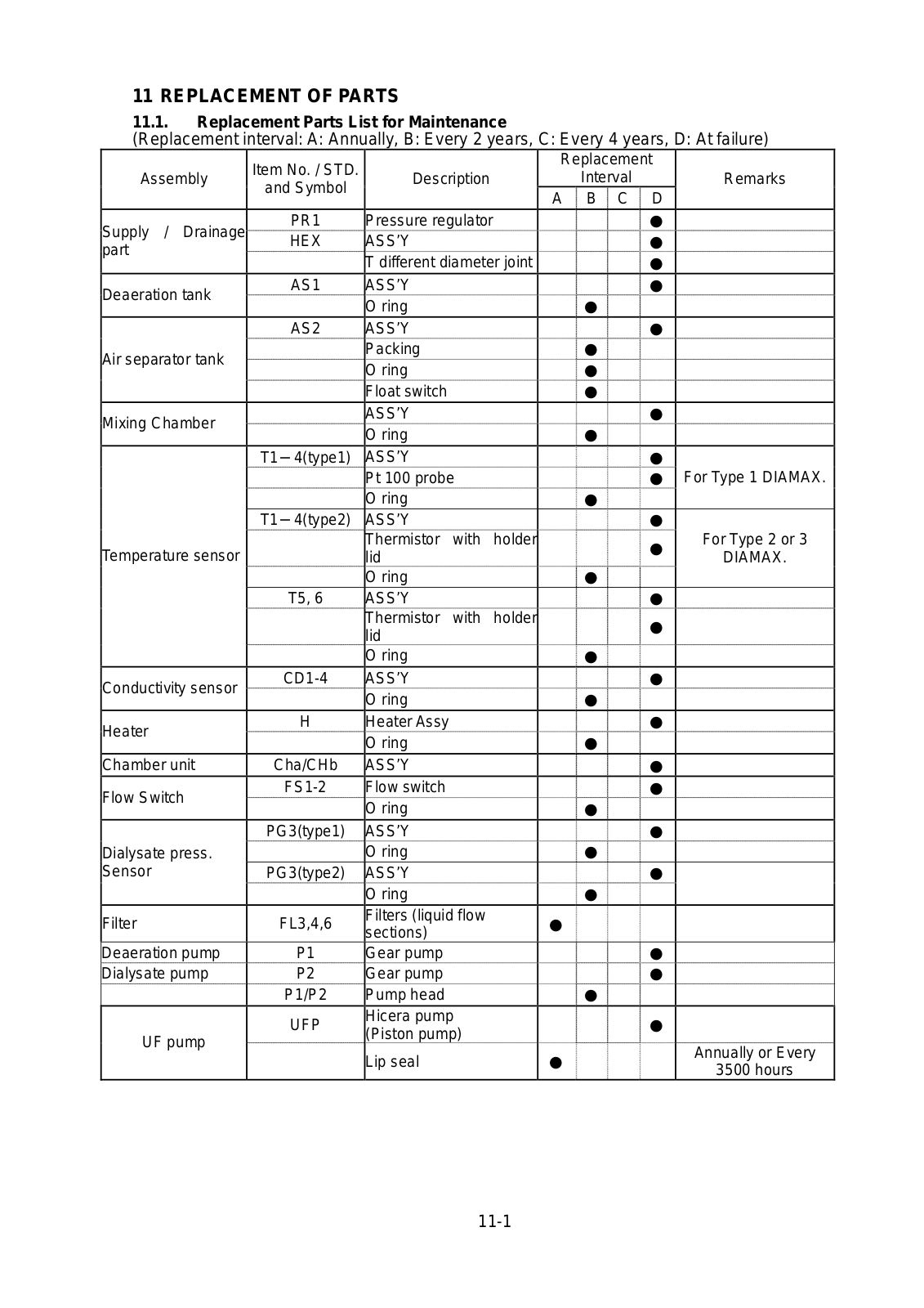
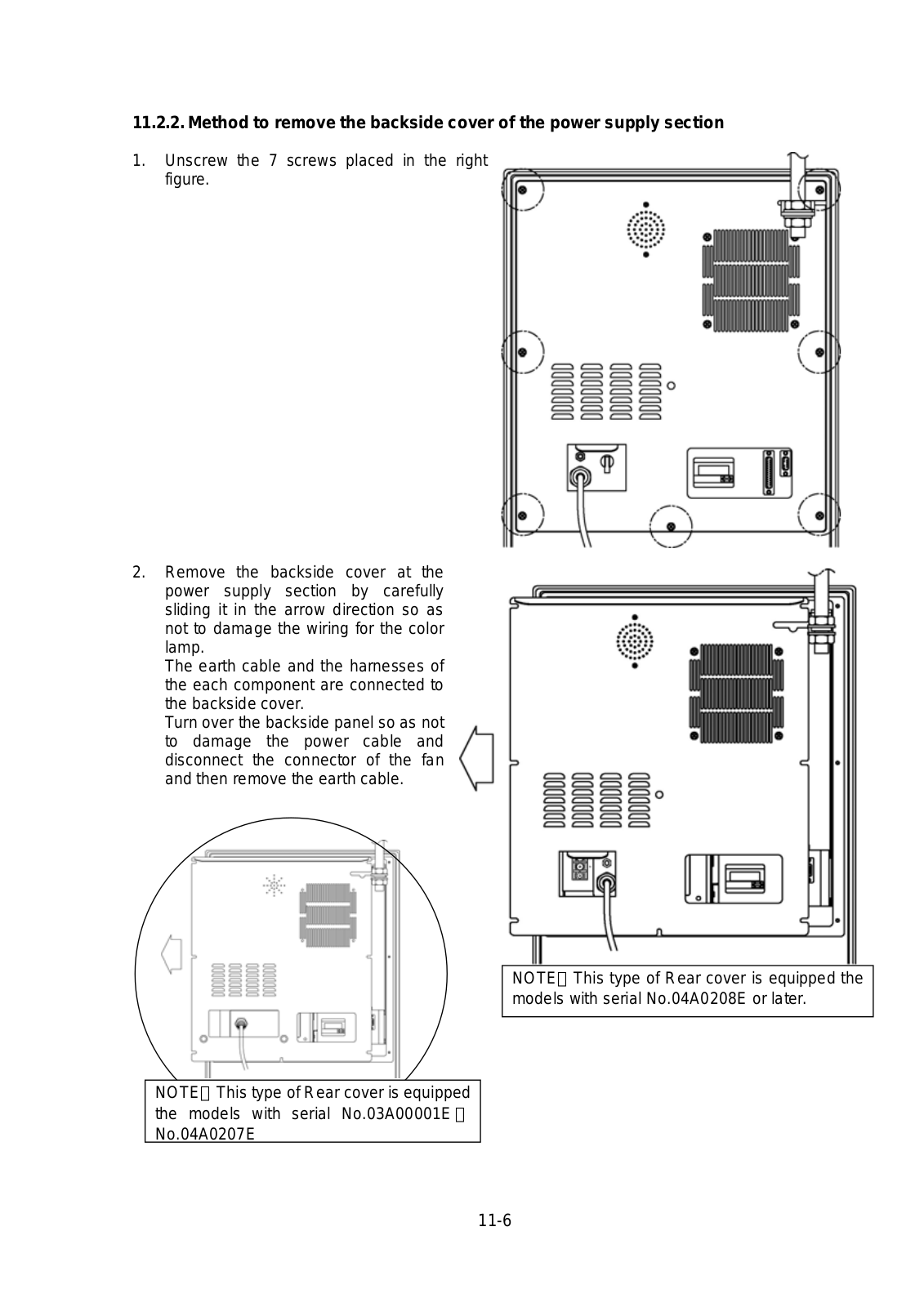
11.1.Replacement Parts List for Maintenance·······································································11-1 11.2.Maintenance of Each Part······························································································11-4 11.2.1.Maintenance of bottom part of machine ······························································11-4 11.2.1.1.Method to open the front door and draw out the dialysate line ·············11-4 11.2.1.2.Method to remove the back cover of the dialysate line section·············11-5 11.2.2.Method to remove the backside cover of the Power supply section ···················11-6 11.2.3.Method to remove the rear cover at the operating panel ····································11-7 11.3.Distinction about Types of DIAMAX···············································································11-8

11.4.Maintenance Parts – Parts List and Replacement Procedure·······································11-12 11.4.1.Pressure Regulator (PR) ·····················································································11-12 11.4.1.1.Pressure regulator (Type 1)···································································11-12 11.4.1.2.Pressure regulator (Type 1): Non adjustment type································11-12 11.4.2.Heat Exchanger (HEX) ························································································11-13 11.4.3.Deaeration buffer tank (AS1) ···············································································11-14 11.4.4.Air Separator tank (AS2)······················································································11-15 11.4.5.Deaeration Chamber (BT1) ·················································································11-16 11.4.6.Temperature Sensor (T1 to 4) ·············································································11-17 11.4.6.1.Temperature sensor (T1 to 4) (Type1: Pt 100Ω) ··································11-17 11.4.6.2.Temperature sensor (T1 to 4) (Type2: Thermistor)·······························11-18 11.4.6.3.Temperature sensor (T5/6)····································································11-19 11.4.7.Conductivity Sensor (CD 1 to 4) ··········································································11-20 11.4.8.Heater and Heater tank ·······················································································11-21 11.4.9.Chamber (CHa, CHb) ··························································································11-23 11.4.10.Flow Switch········································································································11-24 11.4.11.Dialysate Pressure Sensor (PG3)······································································11-25 11.4.11.1.Dialysate Pressure Sensor (Type 1))···················································11-25

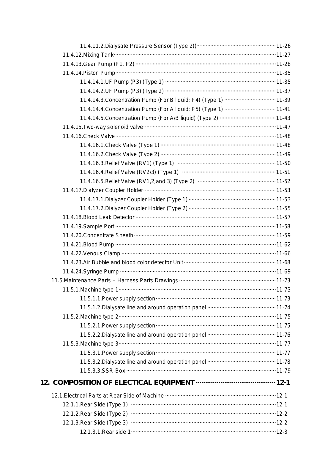
11.4.11.2.Dialysate Pressure Sensor (Type 2))···················································11-26 11.4.12.Mixing Tank········································································································11-27 11.4.13.Gear Pump (P1, P2) ··························································································11-28 11.4.14.Piston Pump·······································································································11-35 11.4.14.1.UF Pump (P3) (Type 1) ·······································································11-35 11.4.14.2.UF Pump (P3) (Type 2) ·······································································11-37 11.4.14.3.Concentration Pump (For B liquid; P4) (Type 1) ·································11-39 11.4.14.4.Concentration Pump (For A liquid; P5) (Type 1) ·································11-41 11.4.14.5.Concentration Pump (For A/B liquid) (Type 2) ····································11-43 11.4.15.Two-way solenoid valve·····················································································11-47 11.4.16.Check Valve·······································································································11-48 11.4.16.1.Check Valve (Type 1) ··········································································11-48 11.4.16.2.Check Valve (Type 2) ··········································································11-49 11.4.16.3.Relief Valve (RV1) (Type 1) ·······························································11-50 11.4.16.4.Relief Valve (RV2/3) (Type 1) ····························································11-51 11.4.16.5.Relief Valve (RV1,2,and 3) (Type 2) ··················································11-52 11.4.17.Dialyzer Coupler Holder·····················································································11-53 11.4.17.1.Dialyzer Coupler Holder (Type 1) ························································11-53 11.4.17.2.Dialyzer Coupler Holder (Type 2) ························································11-55 11.4.18.Blood Leak Detector ··························································································11-57 11.4.19.Sample Port ·······································································································11-58 11.4.20.Concentrate Sheath···························································································11-59 11.4.21.Blood Pump ·······································································································11-62 11.4.22.Venous Clamp ···································································································11-66 11.4.23.Air Bubble and blood color detector Unit ···························································11-68 11.4.24.Syringe Pump ····································································································11-69 11.5.Maintenance Parts – Harness Parts Drawings ······························································11-73 11.5.1.Machine type 1·····································································································11-73 11.5.1.1.Power supply section·············································································11-73 11.5.1.2.Dialysate line and around operation panel ············································11-74 11.5.2.Machine type 2·····································································································11-75 11.5.2.1.Power supply section·············································································11-75 11.5.2.2.Dialysate line and around operation panel ············································11-76 11.5.3.Machine type 3·····································································································11-77 11.5.3.1.Power supply section·············································································11-77 11.5.3.2.Dialysate line and around operation panel ············································11-78 11.5.3.3.SSR-Box ································································································11-79

12. COMPOSITION OF ELECTICAL EQUIPMENT ··········································12-1

12.1.Electrical Parts at Rear Side of Machine ·······································································12-1 12.1.1.Rear Side (Type 1) ·····························································································12-1 12.1.2.Rear Side (Type 2) ·····························································································12-2 12.1.3.Rear Side (Type 3) ·····························································································12-2 12.1.3.1.Rear side 1·····························································································12-3

12.1.3.2.Rear side (SSR Box)··············································································12-4 12.2.Electrical Parts at Inner Side of Front Door around the Hydraulic·································12-5 12.3.Electrical Parts at operation panel ·················································································12-8 12.4.Electrical Parts at Front Side of operation panel····························································12-9

13. CONNECTION AND REPLACEMENT OF P.C.BOARD ·····························13-1

13.1.The Cautions on Replacement / Connection Work of a P.C. Board······························13-1 13.2.Cautions of This Chapter ·······························································································13-1 13.3.LCD Display P.C.Board (BP02-15A, BP02-15B, BP02-15C, BP02-15D)······················13-2 13.3.1.General ················································································································13-2 13.3.2.Function of each part ···························································································13-2 13.3.3.Replacement········································································································13-3 13.3.4.Adjustment···········································································································13-3 13.3.5.Precautions··········································································································13-3 13.4.Control P.C.Board (BP02-16B, BP05-12A, BP05-12B): CPU1 ·····································13-5 13.4.1.General ················································································································13-5 13.4.2.Function of each part ···························································································13-5 13.4.3.Replacement········································································································13-6 13.4.4.Adjustment···········································································································13-7 13.4.5.Precautions··········································································································13-7 13.5.Monitor P.C.Board (BP02-17B, BP02-17C, BP05-13A, BP05-13B): CPU2 ··················13-8 13.5.1.General ················································································································13-8 13.5.2.Function of each part ···························································································13-8 13.5.3.Replacement········································································································13-9 13.5.4.Adjustment···········································································································13-9 13.5.5.Precautions··········································································································13-9

13.6.Driver P.C.Board (BP02-18B, BP05-14A): DRIVER······················································13-10 13.6.1.General ················································································································13-10 13.6.2.Function of each part ···························································································13-10 13.6.3.Replacement········································································································13-11 13.6.4.Adjustment···········································································································13-11 13.6.5.Precautions··········································································································13-11

13.7.Mother P.C.Board (BP02-14A, BP05-11A) ····································································13-12 13.7.1.Part allocation of BP02-14A·················································································13-12 13.7.2.Part allocation of BP05-11A·················································································13-13 13.7.3.General ················································································································13-13 13.7.4.Function of each part ···························································································13-13 13.7.5.Replacement········································································································13-15 13.7.6.Adjustment···········································································································13-15 13.7.7.Precautions··········································································································13-15

13.8.Blood Pressure Sensor P.C.Board (BP01-19B, BP01-19C)··········································13-16 13.8.1.General ················································································································13-16 13.8.2.Function of each part ···························································································13-16

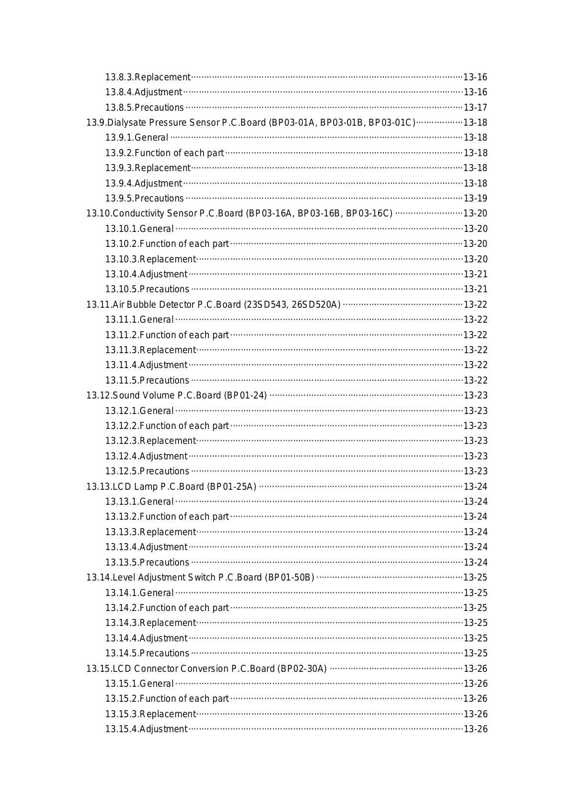
13.8.3.Replacement········································································································13-16 13.8.4.Adjustment···········································································································13-16 13.8.5.Precautions··········································································································13-17 13.9.Dialysate Pressure Sensor P.C.Board (BP03-01A, BP03-01B, BP03-01C)··················13-18 13.9.1.General ················································································································13-18 13.9.2.Function of each part ···························································································13-18 13.9.3.Replacement········································································································13-18 13.9.4.Adjustment···········································································································13-18 13.9.5.Precautions··········································································································13-19 13.10.Conductivity Sensor P.C.Board (BP03-16A, BP03-16B, BP03-16C) ··························13-20 13.10.1.General ··············································································································13-20 13.10.2.Function of each part ·························································································13-20 13.10.3.Replacement······································································································13-20 13.10.4.Adjustment·········································································································13-21 13.10.5.Precautions········································································································13-21 13.11.Air Bubble Detector P.C.Board (23SD543, 26SD520A) ··············································13-22 13.11.1.General ··············································································································13-22 13.11.2.Function of each part ·························································································13-22 13.11.3.Replacement······································································································13-22 13.11.4.Adjustment·········································································································13-22 13.11.5.Precautions········································································································13-22 13.12.Sound Volume P.C.Board (BP01-24) ··········································································13-23 13.12.1.General ··············································································································13-23 13.12.2.Function of each part ·························································································13-23 13.12.3.Replacement······································································································13-23 13.12.4.Adjustment·········································································································13-23 13.12.5.Precautions········································································································13-23 13.13.LCD Lamp P.C.Board (BP01-25A) ··············································································13-24 13.13.1.General ··············································································································13-24 13.13.2.Function of each part ·························································································13-24 13.13.3.Replacement······································································································13-24 13.13.4.Adjustment·········································································································13-24 13.13.5.Precautions········································································································13-24 13.14.Level Adjustment Switch P.C.Board (BP01-50B) ························································13-25 13.14.1.General ··············································································································13-25 13.14.2.Function of each part ·························································································13-25 13.14.3.Replacement······································································································13-25 13.14.4.Adjustment·········································································································13-25 13.14.5.Precautions········································································································13-25 13.15.LCD Connector Conversion P.C.Board (BP02-30A) ···················································13-26 13.15.1.General ··············································································································13-26 13.15.2.Function of each part ·························································································13-26 13.15.3.Replacement······································································································13-26 13.15.4.Adjustment·········································································································13-26

13.15.5.Precautions········································································································13-26 13.16.Connector P.C.Board (BP02-31B, BP02-31C) ····························································13-27 13.16.1.General ··············································································································13-27 13.16.2.Function of each part ·························································································13-27 13.16.3.Replacement······································································································13-28 13.16.4.Adjustment·········································································································13-28 13.16.5.Precautions········································································································13-28 13.17.Pump Driver P.C.Board (BP03-10A, BP03-10B) ·························································13-29 13.17.1.General ··············································································································13-29 13.17.2.Function of each part ·························································································13-29 13.17.3.Replacement······································································································13-29 13.17.4.Adjustment·········································································································13-30 13.17.5.Precautions········································································································13-30 13.18.Inventor P.C.Board (CXA-P1212B-WJL) ·····································································13-31 13.18.1.General ··············································································································13-31 13.18.2.Function of each part ·························································································13-31 13.18.3.Replacement······································································································13-31 13.18.4.Adjustment·········································································································13-31 13.18.5.Precautions········································································································13-31 13.19.UFP encoder P.C.Board (BP05-34)·············································································13-32 13.19.1.General ··············································································································13-32 13.19.2.Function of each part ·························································································13-32 13.19.3.Replacement······································································································13-32 13.19.4.Adjustment·········································································································13-32 13.19.5.Precautions········································································································13-32

14. TECHNICIAN MODE AND MAKER MODE·················································14-1

14.1.TECHNICIAN Mode and MAKER Mode ········································································14-1 14.2.PASS ID Setting the Method··························································································14-2 14.2.1.PASS ID Setting for the MAKER mode ·······························································14-2 14.2.2.PASS ID setting for the TECHNICIAN mode·······················································14-4 14.3.Setting Items on Each Screen ······················································································14-6 14.3.1.Hierarchy of setting menu····················································································14-6

14.3.2.List of setting items in each screen······································································14-10 14.4.Rinse Program Setting and Creating Methods ······························································14-24 14.4.1.Rinse Program creating method··········································································14-24 14.4.2.Notices on creating a rinse program and setting for disinfectant to be used ······14-32 14.4.3.Registering rinse program in rinse standby screen ·············································14-35 14.4.4.Registering WEEKLY RINSE in rinse standby screen ········································14-37 14.5.UF PROFILE Program Creating Method ·······································································14-40 14.6.AB PROFILE Program Creating Method ·······································································14-44

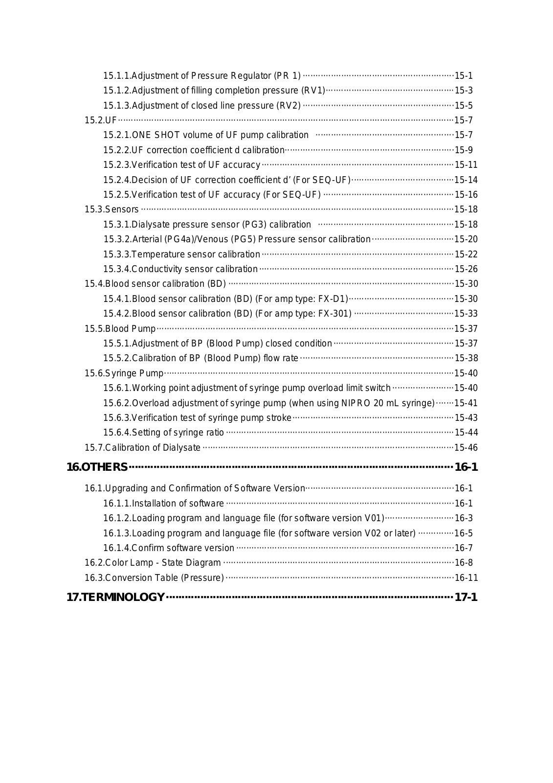
15. ADJUSTMENT ····························································································15-1

15.1.Pressure Regulator and Relief Valve·············································································15-1

15.1.1.Adjustment of Pressure Regulator (PR 1) ···························································15-1 15.1.2.Adjustment of filling completion pressure (RV1)··················································15-3 15.1.3.Adjustment of closed line pressure (RV2) ···························································15-5 15.2.UF···································································································································15-7 15.2.1.ONE SHOT volume of UF pump calibration ······················································15-7 15.2.2.UF correction coefficient d calibration··································································15-9

15.2.3.Verification test of UF accuracy···········································································15-11 15.2.4.Decision of UF correction coefficient d’ (For SEQ-UF)········································15-14 15.2.5.Verification test of UF accuracy (For SEQ-UF) ···················································15-16 15.3.Sensors ··························································································································15-18 15.3.1.Dialysate pressure sensor (PG3) calibration ·····················································15-18 15.3.2.Arterial (PG4a)/Venous (PG5) Pressure sensor calibration································15-20 15.3.3.Temperature sensor calibration···········································································15-22 15.3.4.Conductivity sensor calibration············································································15-26 15.4.Blood sensor calibration (BD) ························································································15-30 15.4.1.Blood sensor calibration (BD) (For amp type: FX-D1)·········································15-30 15.4.2.Blood sensor calibration (BD) (For amp type: FX-301) ·······································15-33 15.5.Blood Pump····················································································································15-37 15.5.1.Adjustment of BP (Blood Pump) closed condition···············································15-37 15.5.2.Calibration of BP (Blood Pump) flow rate ····························································15-38 15.6.Syringe Pump·················································································································15-40 15.6.1.Working point adjustment of syringe pump overload limit switch ························15-40 15.6.2.Overload adjustment of syringe pump (when using NIPRO 20 mL syringe)·······15-41 15.6.3.Verification test of syringe pump stroke·······························································15-43 15.6.4.Setting of syringe ratio ·························································································15-44 15.7.Calibration of Dialysate ··································································································15-46

16.OTHERS········································································································16-1

16.1.Upgrading and Confirmation of Software Version··························································16-1 16.1.1.Installation of software ·························································································16-1 16.1.2.Loading program and language file (for software version V01)···························16-3 16.1.3.Loading program and language file (for software version V02 or later) ··············16-5 16.1.4.Confirm software version ·····················································································16-7

16.2.Color Lamp - State Diagram ··························································································16-8 16.3.Conversion Table (Pressure) ·························································································16-11

17.TERMINOLOGY····························································································17-1

1APPLICATION

(a)Single patient dialysis machine, DIAMAX is applied to treatment of patients with acute or chronic renal failure by dialysis when doctors instruct the application.

(b)DIAMAX can be used in a controlled environment such as a place in a hospital.

1-1

2 CONTRAINDICATION

Any application other than dialysis using DIAMAX is contraindicated.

2-1

3 PRECAUTIONS

Service life of this machine is 6 years.

3.1.Equipment Classification and Handling precautions

This machine is classified as follows:

Type of protection from electric shock ····················Class Degree of protection from electric shock ··················Type B Ensure to have a protective earth connection with the equipped power plug.

3.2.Precaution for Fluid Penetration

Keep the machine out of water.

3.3.Precaution for Flammable Atmospheres

Do not use this machine in flammable atmospheres.

3.4.Safety Precautions

Appropriate operation and regular maintenance are essential for safer use of this machine. Carefully read and thoroughly understand the safety precautions described in this manual before

using or servicing this machine.

The operating procedures and precautions described in this manual are effective only when this machine is used for its intended purposes. Users shall be liable for all deeds and the safety measures taken when the machine is used in methods other than specified in this manual.

1. Degree of damage to health and property, and its indication (Alert symbols and signal words)

The degree of the foreseeable damage to health and property when the machine is misused is classified into the following three categories, and each category is expressed by the following alert symbol and signal word.

DANGER

Indicates an imminent hazardous situation which, if the machine is misused, will result in death or serious injury.

WARNING

Indicates a potentially hazardous situation which, if the machine is misused, will result in death or serious injury.

3-1

CAUTION

Indicates a potentially hazardous situation which, if the machine is misused, may result in minor or moderate injury or property damage.

2. Note and its indication

NOTE

Indicates note sentences. Make reference when operating or servicing the machine.

3-2

DANGER

Before using the machine, be sure to read this manual.

This machine operates in a safe and reliable manner when operated and serviced as specified in this manual.

Carefully read and thoroughly understand this manual before operating this machine. Incorrect operation may endanger individual person or damage the machine.

This machine shall be operated by trained qualified personnel at a hospital under the supervision by a doctor.

Know the method to stop this machine immediately.

Know the method to stop this machine immediately in order to prevent the occurrence of serious troubles.

Do not allow non-professionals to operate the unit without having proper instructions.

Know the measures to take in case when this machine has stopped due to some troubles.

• Check the condition of the machine and take appropriate measures according to the instructions described in this manual.

Do not touch any printed wiring boards, electric wiring, and terminals except when servicing this machine.

Do not touch any electric wiring and terminals not isolated.

Do not touch any printed wiring boards with wet hands.

Turn OFF the breaker when touching a printed wiring board, electric wiring, or terminals.

Take special caution on the following foreseeable risk of danger to a patient when he or she is connected to or disconnected from the line of the machine for medical treatment.

Air must not enter the body of a patient.

Do not connect a patient to the blood line before priming.

Do not connect a patient to the blood line when this machine is being rinsed.

Take caution so that any harmful viruses or chemicals do not enter the body of a patient.

Always confirm that a patient is appropriately connected to the blood line. Improper connection to the blood line may endanger a patient by the blood leak due to the poor connection, rupture of the blood line due to inappropriate pressure rise, etc.

3-3

WARNING

Do not change any set values during a treatment except for the case in emergency.

Change set values before connecting a patient.

When making a setting for a function, thoroughly understand the function to use in advance.

Take caution to keep the power cable off the floor to prevent an electric shock due to the leaked water on the floor when this machine is defected.

Furnish drainage near this machine.

Be sure to read maintenance manual before servicing the machine.

Read carefully and thoroughly understand maintenance manual before servicing the machine.

Service the machine according to the instructions described in the maintenance manual.

Ask special maintenance personnel for the maintenance other than specified in the maintenance manual.

Do not operate any switches unnecessarily during dialysis treatment.

Do not tilt the machine by five (5) degrees or more under the conditions where something is put on the disinfectant tank table, hanger, tray, etc. Otherwise, the machine may fall.

Do not put anything on the disinfectant tank table, hanger, tray, etc when moving the machine.

Do not tilt the machine by ten (10) degrees or more. Otherwise, the machine may fall.

Do not connect any equipment other than allowed with this machine.

(Total leakage current (of this machine and other connected equipment) may exceed the allowable value).

Usages other than specified by the manufacturer may cause injury or death of a patient. The manufacturer will not liable for any troubles including damage to health of a patient if this machine is operated, serviced, or calibrated in a manner other than specified by the manufacturer. Only a trained qualified person must operate this machine in the method specified by the manufacturer.

Check the real concentration by the Laboratory.

Confirm that the real concentration is correct, using an osmotic pressure meter, a conductivity meter, a flame photometer, etc.

Confirm that the conductivity displayed on the machine is correct.

Confirm neither disinfectant nor acid fluid remains after rinsing is complete.

After disinfection by sodium hypochloride or peracetic acid or acid cleaning by acetic

3-4

acids is complete, confirm neither disinfectant nor acidic fluid remains in the fluid supply part and drainage part using test papers or reagent.

3-5

CAUTION

Read and understand the installation procedures described in the maintenance manual before installing this machine.

Only the person who was trained qualified personnel must install this machine.

Read and understand the instruction manual of optional parts before connecting such optional parts to this machine.

Only the person who was trained qualified personnel must install this machine.

Do not give strong force or shock to the display and operation panel.

• Take caution not to give strong force or shock to the display and operation panel during cleaning.

Sufficiently disinfect the machine before using it.

Rinse the machine for one hour or longer when it has not been used for a long period of time.

When using the machine that has not been used for a long period of time without draining, clean it until clean water comes out from the drain outlet.

Be sure to always keep the machine clean.

Wipe off droplets and stains of blood, dialysate, cleaning solution as soon as possible.

Perform rinsing and disinfection regularly.

Some processes do not accept specific switches. In such cases, do not operate switches forcedly.

Be sure to use the dialysate concentrate in properly color-coded container. The dialysate concentrate not contained in a color-coded container cannot be used with this machine.

Use only disposable products affixed with CE marking.

A person who handles disposable products may touch hepatitis virus or other infectious medicals. Take extreme caution not to be infected when operating this machine.

Assure the quality of water, dialysate concentrate, and substitution fluid used for the machine operation in order to secure performance and safety.

3-6

3.5.Precautions

1.Allow only skilled personnel to operate the machine.

2.Take caution on the following points when installing the machine.

1)Install at a place where water does not splash on the machine.

2)Install at a place where the machine does not receive adverse effect from the atmospheric pressure, temperature, humidity, ventilation, sunlight, and atmosphere that includes dust, salty, sulfur, etc.

3)Take caution on the stability of the machine not to give it inclination, vibration, and shocks (including the time of transportation).

4)Avoid a storage of chemicals or a place where gases are generated.

5)Pay attention to the frequency, voltage, and permissible current (or power consumption) of the power supply.

6)Check the state of the power supply (state of the electrical discharge, polarity, etc.).

7)Connect the earth properly.

3.Take caution on the following points before using the machine.

1)Check the conditions of switch contacts and verify that the machine operates properly.

2)Confirm the grounding is ensured.

3)Confirm that all the cable connections are correct and safe.

4)Take sufficient caution when using the machine in combination with other machines since it may obstruct correct operation or cause danger.

5)Verify that there is neither deforming nor discoloration in the appearance and other

features of the machine.

4)Take caution on the following points when using the machine.

1)Always observe that there is no abnormality in the operation of the machine and with a patient.

2)If some abnormality has occurred with the machine, take appropriate measures such as stopping the machine in a safe condition for the patient.

3)Do not raise the dialysate pressure above the allowable limit.

4)Take caution so that a patient does not touch the machine.

5)Do not give any strong vibration to the machine.

6)Do not bring any electromagnetic wave source close to the machine since it may

cause a breakdown or malfunction of the machine.

5.Take caution on the following points after using the machine.

1)Turn OFF the power supply of the machine to return the machine to the condition before use according to the specified procedures.

2)Do not give unnecessary force in pulling the power and other cables for disconnection, but hold the plug.

3)Take caution on the following points for the storage of the machine. a. Keep at a place where no water splashes on the machine.

3-7

b.Keep at a place where the machine does not receive adverse effect from the atmospheric pressure, temperature, humidity, ventilation, sunlight, and atmosphere that includes dust, salty, sulfur, etc.

c.Take caution on the stability of the machine not to give it inclination, vibration, and shocks (including the time of transportation).

d.Avoid storage of chemicals at a place where gases are generated.

4)Put away the accessories, cables, and electrode, etc. together at an appointed place after cleaning.

5)Always rinse and clean the machine after use to prepare for the next use.

6)Always keep the filter of the cooling fan clean.

6.If the machine is defected, check the trouble cause on the appropriate display and ask the special maintenance personnel for repair without fiddling it by yourself.

7.Do not modify the machine.

8.Maintenance

1)Make the special maintenance personnel check the machine and its parts periodically.

2)Confirm that the machine operates properly and safely when operating the machine that has not been used for a certain period of time.

9.Others

1)Check the concentration of the dialysate before use by the osmotic pressure measurement method and the like.

2)(Concerning the water to dilute the dialysate concentrate:) AAMI standards water is recommended for the water to dilute the dialysate concentrate used for the chronic dialysis treatment.

3.6.Precaution for Software

The Version number of manuals is described on the front cover of each document.

These documents are corresponded with this software version. Please check the list below for compliance with the software version and these documents before usage.

You can check the software version in the start-up screen.

Documents / Version

Software Version


Instruction Manual

PrCMX1001-0606


Ver. CE 00

Maintenance Manual

PrCMX2001-0606


Troubleshooting Manual

PrCMX3001-0606


3-8

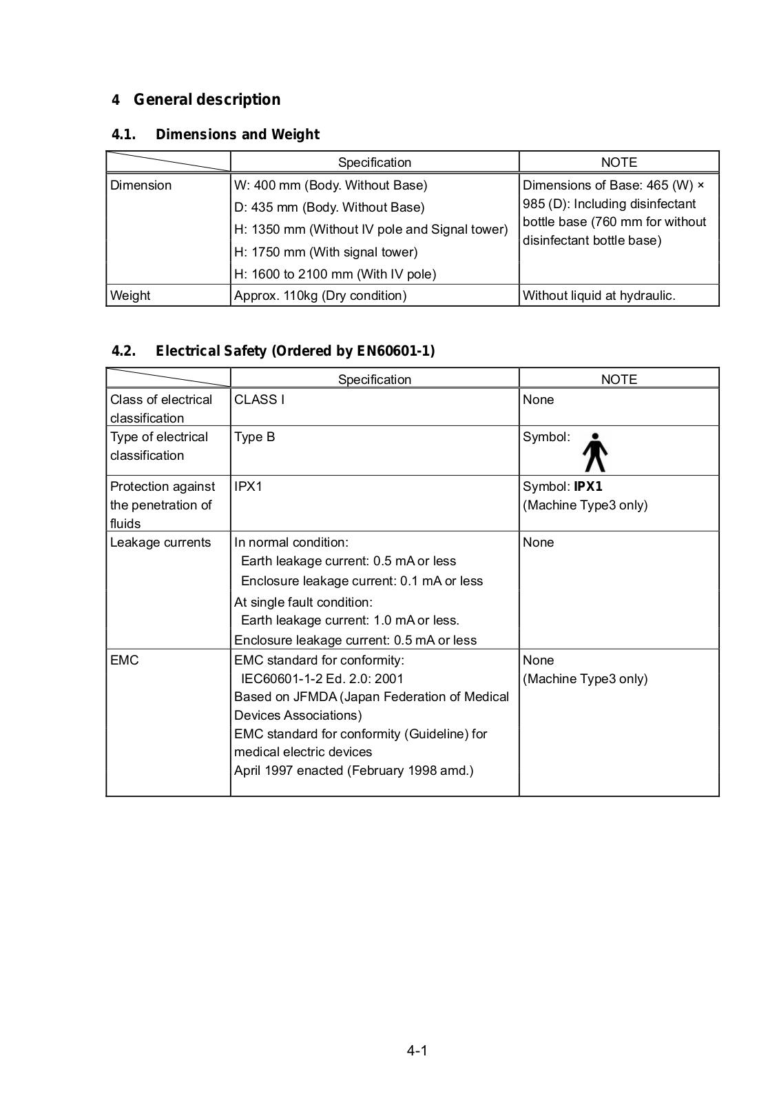
4 General description

4.1.Dimensions and Weight


Specification


Dimension

W: 400 mm (Body. Without Base)


D: 435 mm (Body. Without Base)


H: 1350 mm (Without IV pole and Signal tower)


H: 1750 mm (With signal tower)


H: 1600 to 2100 mm (With IV pole)


Weight

Approx. 110kg (Dry condition)


NOTE

Dimensions of Base: 465 (W) × 985 (D): Including disinfectant bottle base (760 mm for without disinfectant bottle base)

Without liquid at hydraulic.

4.2.Electrical Safety (Ordered by EN60601-1)


Specification

NOTE

Class of electrical

CLASS I

None

classification


Type of electrical

Type B

Symbol:

classification


Protection against

IPX1

Symbol: IPX1

the penetration of


(Machine Type3 only)

fluids


Leakage currents

In normal condition:

None


Earth leakage current: 0.5 mA or less


Enclosure leakage current: 0.1 mA or less


At single fault condition:


Earth leakage current: 1.0 mA or less.


Enclosure leakage current: 0.5 mA or less


EMC

EMC standard for conformity:

None


IEC60601-1-2 Ed. 2.0: 2001

(Machine Type3 only)


Based on JFMDA (Japan Federation of Medical


Devices Associations)


EMC standard for conformity (Guideline) for


medical electric devices


April 1997 enacted (February 1998 amd.)


4-1

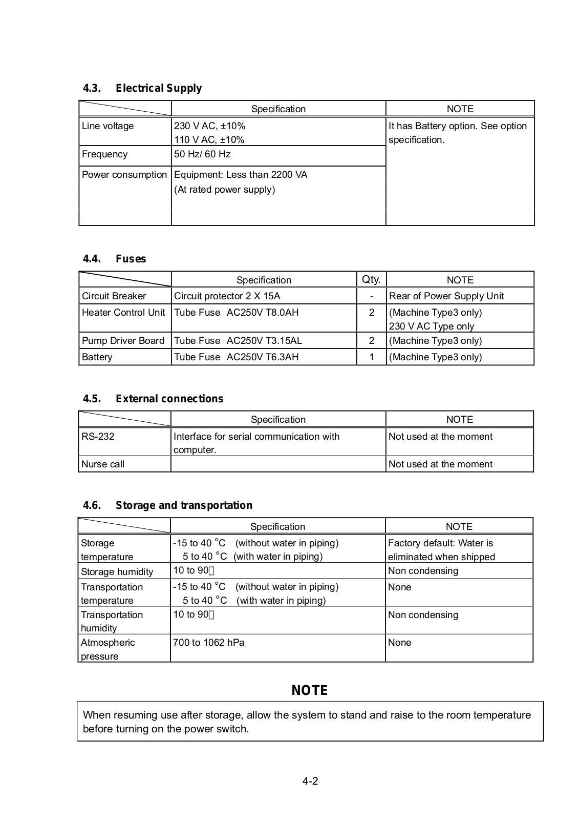
4.3.Electrical Supply


Specification


NOTE


It has Battery option. See option

Line voltage

230 V AC, ±10%


110 V AC, ±10%


specification.

Frequency

50 Hz/ 60 Hz


Power consumption

Equipment: Less than 2200 VA


(At rated power supply)


4.4. Fuses


Specification

Qty.

NOTE

Circuit Breaker

Circuit protector 2 X 15A

-

Rear of Power Supply Unit


Heater Control Unit

Tube Fuse

AC250V T8.0AH

2

(Machine Type3 only)


230 V AC Type only

Pump Driver Board

Tube Fuse

AC250V T3.15AL

2

(Machine Type3 only)

Battery

Tube Fuse

AC250V T6.3AH

1

(Machine Type3 only)


4.5.External connections


Specification


NOTE


RS-232

Interface for serial communication with


Not used at the moment


computer.


Nurse call


Not used at the moment


4.6.Storage and transportation


Specification

NOTE


Storage

-15 to 40 °C (without water in piping)

Factory default: Water is

temperature

5 to 40 °C (with water in piping)

eliminated when shipped

Storage humidity

10 to 90

Non condensing

Transportation

-15 to 40 °C (without water in piping)

None

temperature

5 to 40 °C (with water in piping)


Transportation

10 to 90

Non condensing

humidity


Atmospheric

700 to 1062 hPa

None

pressure


NOTE

When resuming use after storage, allow the system to stand and raise to the room temperature before turning on the power switch.

4-2

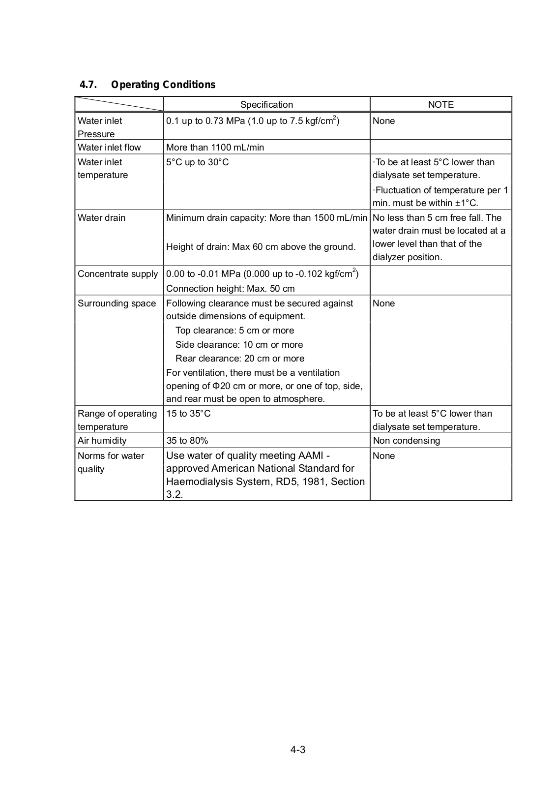
4.7.Operating Conditions


Specification

NOTE


Water inlet

0.1 up to 0.73 MPa (1.0 up to 7.5 kgf/cm2)

None

Pressure


Water inlet flow

More than 1100 mL/min


Water inlet

5°C up to 30°C

·To be at least 5°C lower than

temperature


dialysate set temperature.


·Fluctuation of temperature per 1


min. must be within ±1°C.

Water drain

Minimum drain capacity: More than 1500 mL/min

No less than 5 cm free fall. The


water drain must be located at a


Height of drain: Max 60 cm above the ground.

lower level than that of the


dialyzer position.


Concentrate supply

0.00 to -0.01 MPa (0.000 up to -0.102 kgf/cm2)


Connection height: Max. 50 cm


Surrounding space

Following clearance must be secured against

None


outside dimensions of equipment.


Top clearance: 5 cm or more


Side clearance: 10 cm or more


Rear clearance: 20 cm or more


For ventilation, there must be a ventilation


opening of Φ20 cm or more, or one of top, side,


and rear must be open to atmosphere.


Range of operating

15 to 35°C

To be at least 5°C lower than

temperature


dialysate set temperature.

Air humidity

35 to 80%

Non condensing


Norms for water

Use water of quality meeting AAMI -

None

quality

approved American National Standard for


Haemodialysis System, RD5, 1981, Section


3.2.


4-3

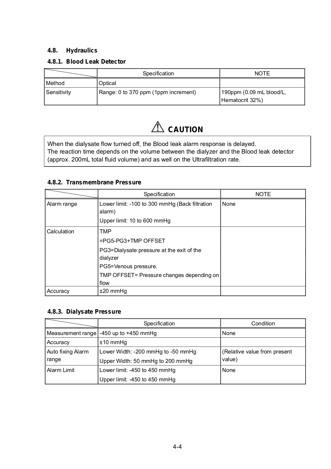
4.8.Hydraulics

4.8.1. Blood Leak Detector


Specification


NOTE


Method

Optical


Sensitivity

Range: 0 to 370 ppm (1ppm increment)


190ppm (0.09 mL blood/L,


Hematocrit 32%)


CAUTION

When the dialysate flow turned off, the Blood leak alarm response is delayed.

The reaction time depends on the volume between the dialyzer and the Blood leak detector (approx. 200mL total fluid volume) and as well on the Ultrafiltration rate.

4.8.2. Transmembrane Pressure


Specification


NOTE


Alarm range

Lower limit: -100 to 300 mmHg (Back filtration


None


alarm)


Upper limit: 10 to 600 mmHg


Calculation

TMP


=PG5-PG3+TMP OFFSET


PG3=Dialysate pressure at the exit of the


dialyzer


PG5=Venous pressure.


TMP OFFSET= Pressure changes depending on


flow


Accuracy

±20 mmHg


4.8.3. Dialysate Pressure


Specification


Condition


Measurement range

-450 up to +450 mmHg


None

Accuracy

±10 mmHg


Auto fixing Alarm

Lower Width: -200 mmHg to -50 mmHg


(Relative value from present

range

Upper Width: 50 mmHg to 200 mmHg


value)

Alarm Limit

Lower limit: -450 to 450 mmHg


None


Upper limit: -450 to 450 mmHg


4-4

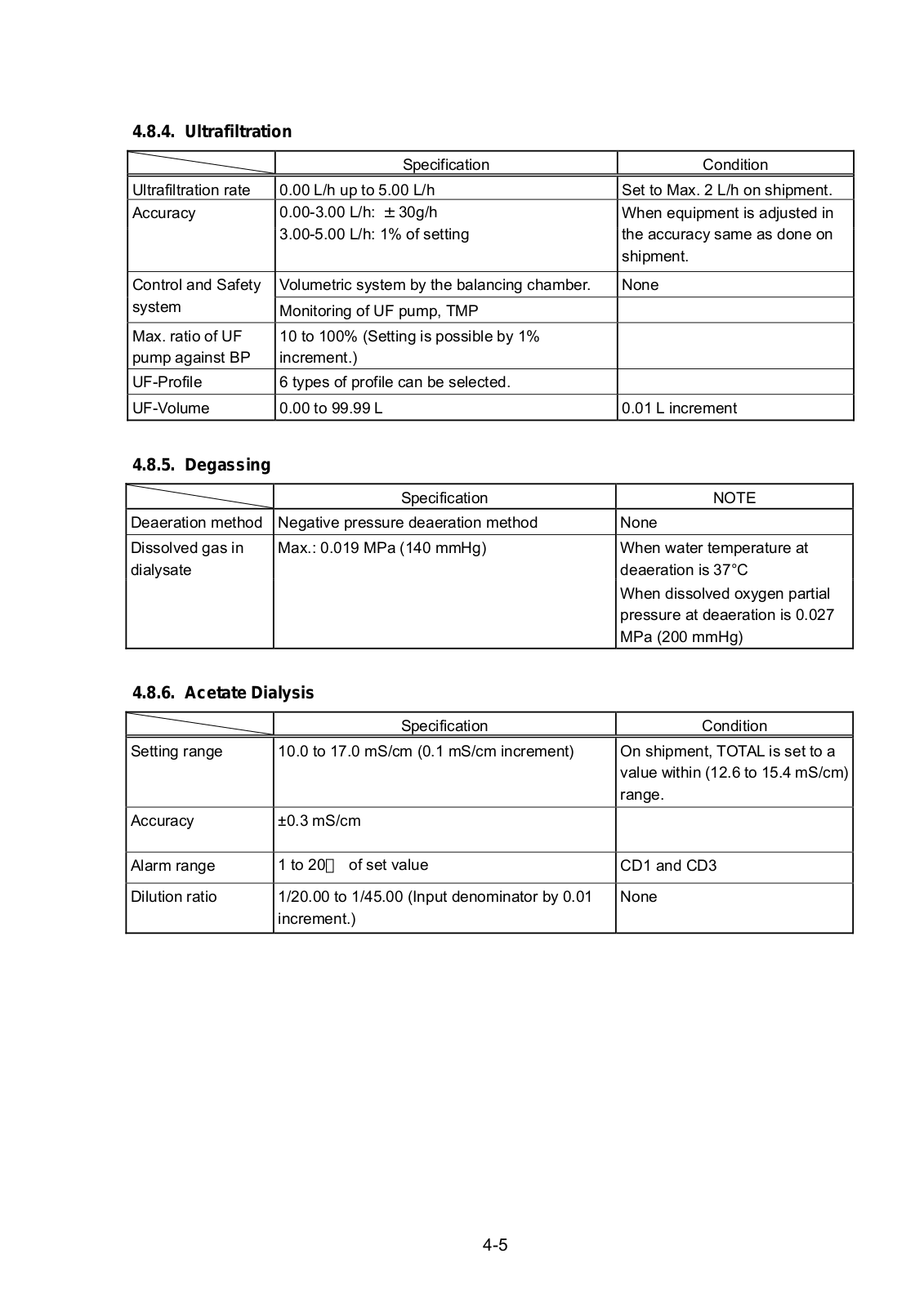
4.8.4. Ultrafiltration


Specification

Condition


Ultrafiltration rate

0.00 L/h up to 5.00 L/h

Set to Max. 2 L/h on shipment.

Accuracy

0.00-3.00 L/h: ±30g/h

When equipment is adjusted in


3.00-5.00 L/h: 1% of setting

the accuracy same as done on


shipment.


Control and Safety

Volumetric system by the balancing chamber.

None

system

Monitoring of UF pump, TMP


Max. ratio of UF

10 to 100% (Setting is possible by 1%


pump against BP

increment.)


UF-Profile

6 types of profile can be selected.


UF-Volume

0.00 to 99.99 L

0.01 L increment


4.8.5. Degassing


Specification

NOTE

Deaeration method

Negative pressure deaeration method

None

Dissolved gas in

Max.: 0.019 MPa (140 mmHg)

When water temperature at

dialysate


deaeration is 37°C


When dissolved oxygen partial


pressure at deaeration is 0.027


MPa (200 mmHg)

4.8.6. Acetate Dialysis


Specification


Condition


Setting range

10.0 to 17.0 mS/cm (0.1 mS/cm increment)


On shipment, TOTAL is set to a


value within (12.6 to 15.4 mS/cm)


range.

Accuracy

±0.3 mS/cm


Alarm range

1 to 20 of set value


CD1 and CD3


Dilution ratio

1/20.00 to 1/45.00 (Input denominator by 0.01


None


increment.)


4-5

NIPRO DIAMAX User manual

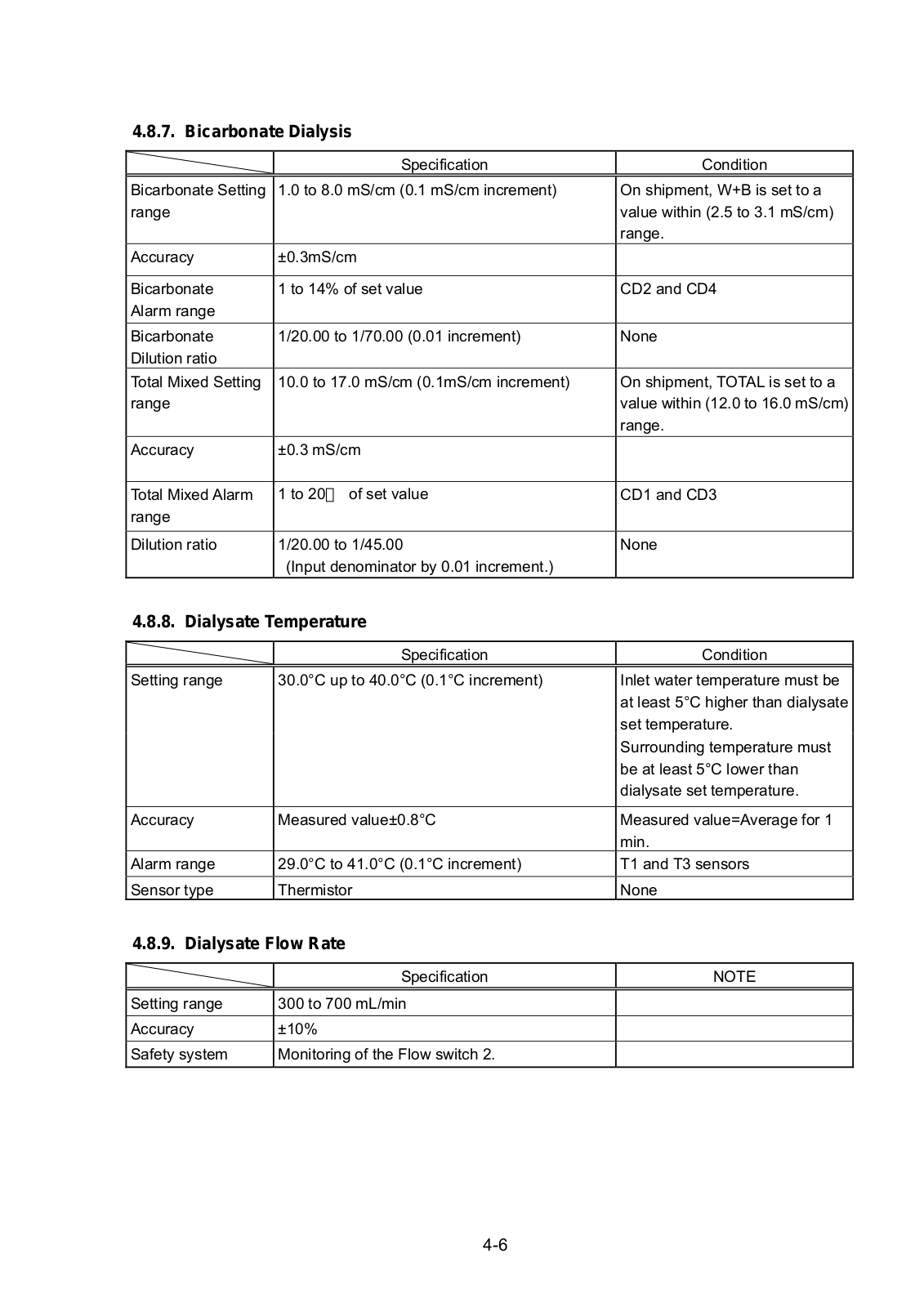
4.8.7. Bicarbonate Dialysis

Specification

Bicarbonate Setting 1.0 to 8.0 mS/cm (0.1 mS/cm increment) range

Accuracy

±0.3mS/cm


Bicarbonate

1 to 14% of set value

Alarm range


Bicarbonate

1/20.00 to 1/70.00 (0.01 increment)

Dilution ratio


Total Mixed Setting

10.0 to 17.0 mS/cm (0.1mS/cm increment)

range


Accuracy

±0.3 mS/cm


Total Mixed Alarm

1 to 20 of set value

range


Dilution ratio

1/20.00 to 1/45.00


(Input denominator by 0.01 increment.)

4.8.8. Dialysate Temperature


Specification


Setting range

30.0°C up to 40.0°C (0.1°C increment)

Accuracy

Measured value±0.8°C


Alarm range

29.0°C to 41.0°C (0.1°C increment)


Sensor type

Thermistor

4.8.9. Dialysate Flow Rate


Specification


Setting range

300 to 700 mL/min


Accuracy

±10%


Safety system

Monitoring of the Flow switch 2.


4-6

Condition

On shipment, W+B is set to a value within (2.5 to 3.1 mS/cm) range.

CD2 and CD4

None

On shipment, TOTAL is set to a value within (12.0 to 16.0 mS/cm) range.

CD1 and CD3

None

Condition

Inlet water temperature must be at least 5°C higher than dialysate set temperature.

Surrounding temperature must be at least 5°C lower than dialysate set temperature.

Measured value=Average for 1 min.

T1 and T3 sensors None

NOTE

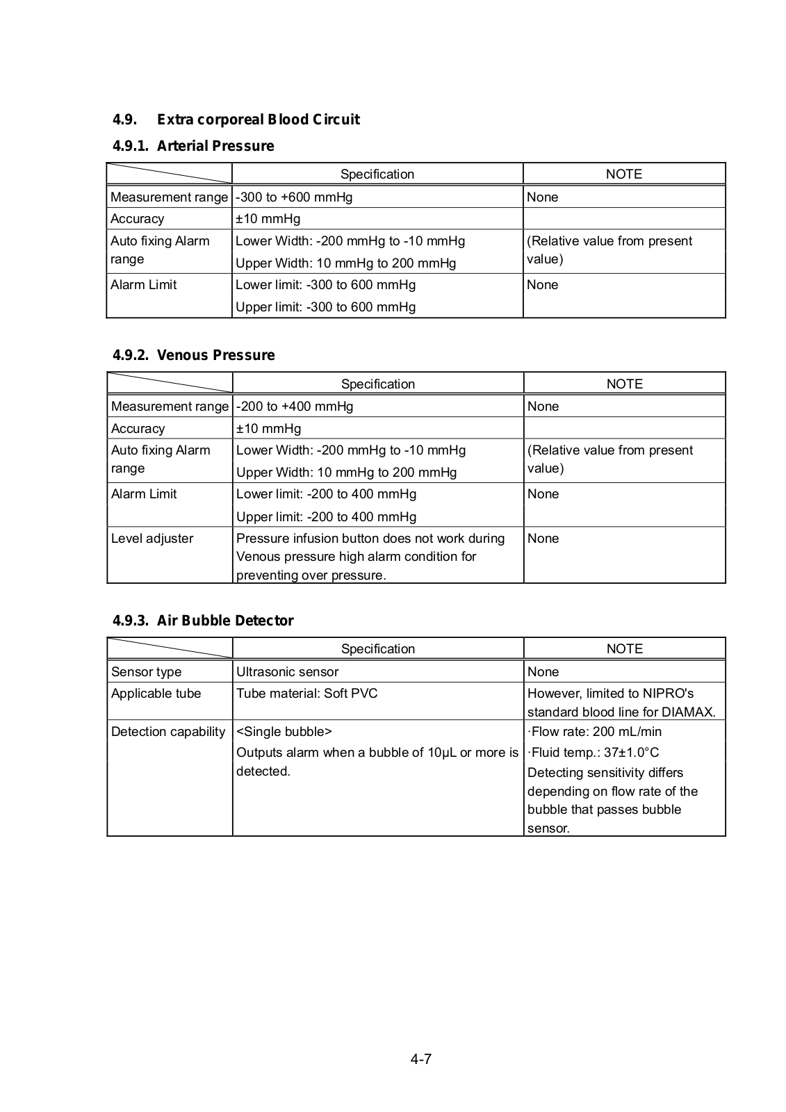
4.9. Extra corporeal Blood Circuit 4.9.1. Arterial Pressure


Specification

NOTE


Measurement range

-300 to +600 mmHg

None

Accuracy

±10 mmHg


Auto fixing Alarm

Lower Width: -200 mmHg to -10 mmHg

(Relative value from present

range

Upper Width: 10 mmHg to 200 mmHg

value)

Alarm Limit

Lower limit: -300 to 600 mmHg

None


Upper limit: -300 to 600 mmHg


4.9.2. Venous Pressure


Specification


NOTE


Measurement range

-200 to +400 mmHg


None


Accuracy

±10 mmHg


Auto fixing Alarm

Lower Width: -200 mmHg to -10 mmHg


(Relative value from present

range

Upper Width: 10 mmHg to 200 mmHg


value)

Alarm Limit

Lower limit: -200 to 400 mmHg


None


Upper limit: -200 to 400 mmHg


Level adjuster

Pressure infusion button does not work during


None


Venous pressure high alarm condition for


preventing over pressure.


4.9.3. Air Bubble Detector


Specification


NOTE


Sensor type

Ultrasonic sensor


None

Applicable tube

Tube material: Soft PVC


However, limited to NIPRO's


standard blood line for DIAMAX.

Detection capability

<Single bubble>


·Flow rate: 200 mL/min


Outputs alarm when a bubble of 10µL or more is


·Fluid temp.: 37±1.0°C


detected.


Detecting sensitivity differs


depending on flow rate of the


bubble that passes bubble


sensor.

4-7

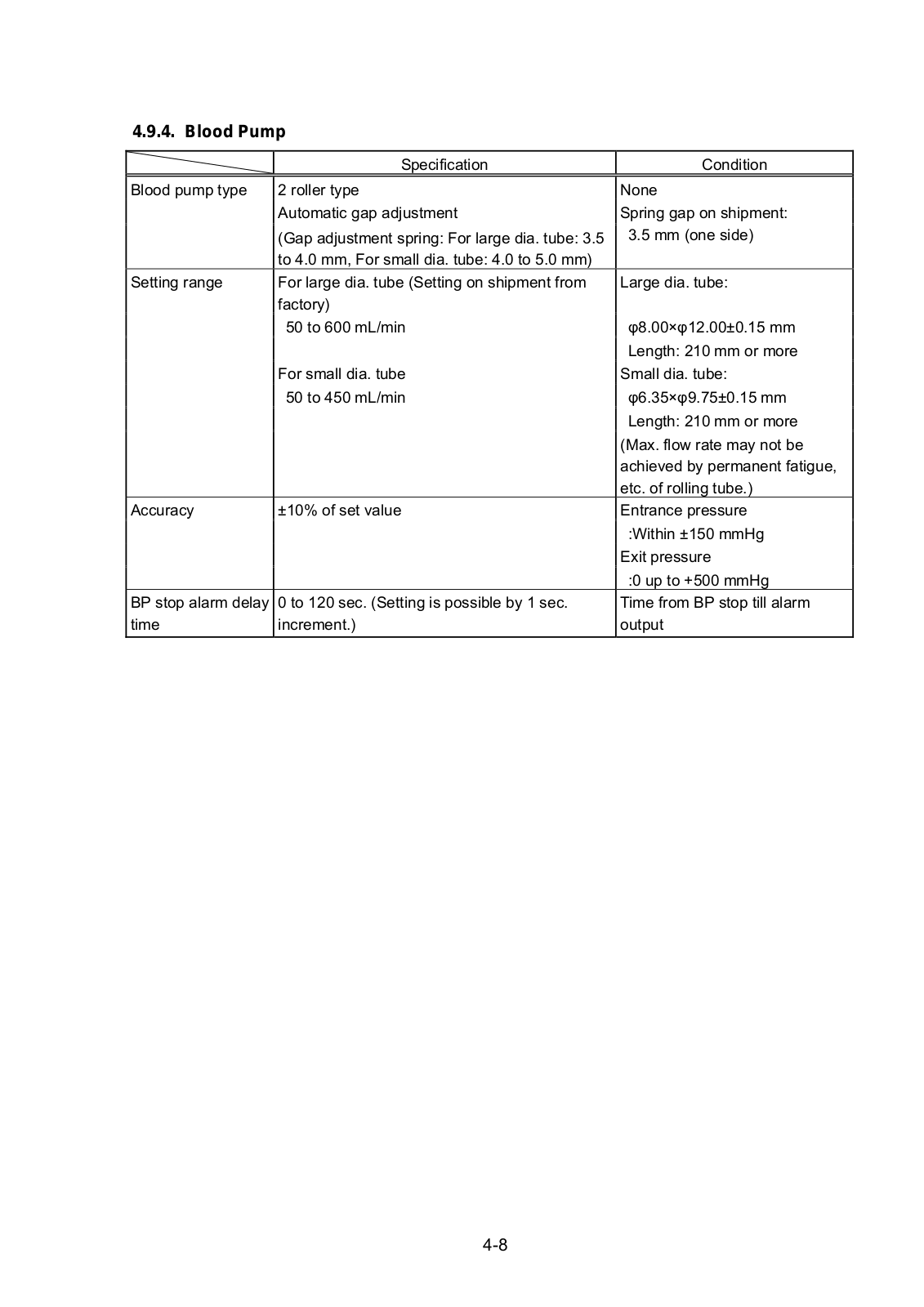
4.9.4. Blood Pump


Specification


Condition


Blood pump type

2 roller type


None


Automatic gap adjustment


Spring gap on shipment:


(Gap adjustment spring: For large dia. tube: 3.5


3.5 mm (one side)


to 4.0 mm, For small dia. tube: 4.0 to 5.0 mm)


Setting range

For large dia. tube (Setting on shipment from


Large dia. tube:


factory)


50 to 600 mL/min


φ8.00×φ12.00±0.15 mm


Length: 210 mm or more


For small dia. tube


Small dia. tube:


50 to 450 mL/min


φ6.35×φ9.75±0.15 mm


Length: 210 mm or more


(Max. flow rate may not be


achieved by permanent fatigue,


etc. of rolling tube.)

Accuracy

±10% of set value


Entrance pressure


:Within ±150 mmHg


Exit pressure


:0 up to +500 mmHg

BP stop alarm delay

0 to 120 sec. (Setting is possible by 1 sec.


Time from BP stop till alarm

time

increment.)


output

4-8

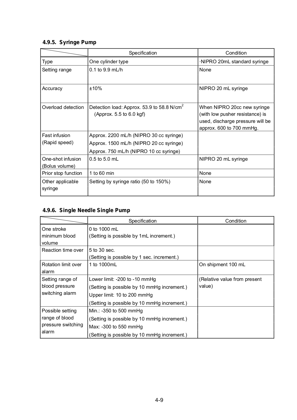
4.9.5. Syringe Pump


Specification


Type

One cylinder type


Setting range

0.1 to 9.9 mL/h


Accuracy

±10%


Overload detection

Detection load: Approx. 53.9 to 58.8 N/cm2


(Approx. 5.5 to 6.0 kgf)


Fast infusion

Approx. 2200 mL/h (NIPRO 30 cc syringe)


(Rapid speed)

Approx. 1500 mL/h (NIPRO 20 cc syringe)


Approx. 750 mL/h (NIPRO 10 cc syringe)


One-shot infusion

0.5 to 5.0 mL


(Bolus volume)


Prior stop function

1 to 60 min


Other applicable

Setting by syringe ratio (50 to 150%)


syringe


4.9.6. Single Needle Single Pump

Condition

·NIPRO 20mL standard syringe None

NIPRO 20 mL syringe

When NIPRO 20cc new syringe (with low pusher resistance) is used, discharge pressure will be approx. 600 to 700 mmHg.

NIPRO 20 mL syringe

None

None


Specification

Condition


One stroke

0 to 1000 mL


minimum blood

(Setting is possible by 1mL increment.)


volume


Reaction time over

5 to 30 sec.


(Setting is possible by 1 sec. increment.)


Rotation limit over

1 to 1000mL

On shipment 100 mL

alarm


Setting range of

Lower limit: -200 to -10 mmHg

(Relative value from present

blood pressure

(Setting is possible by 10 mmHg increment.)

value)

switching alarm

Upper limit: 10 to 200 mmHg


(Setting is possible by 10 mmHg increment.)


Possible setting

Min.: -350 to 500 mmHg


range of blood

(Setting is possible by 10 mmHg increment.)


pressure switching

Max: -300 to 550 mmHg


alarm


(Setting is possible by 10 mmHg increment.)


4-9

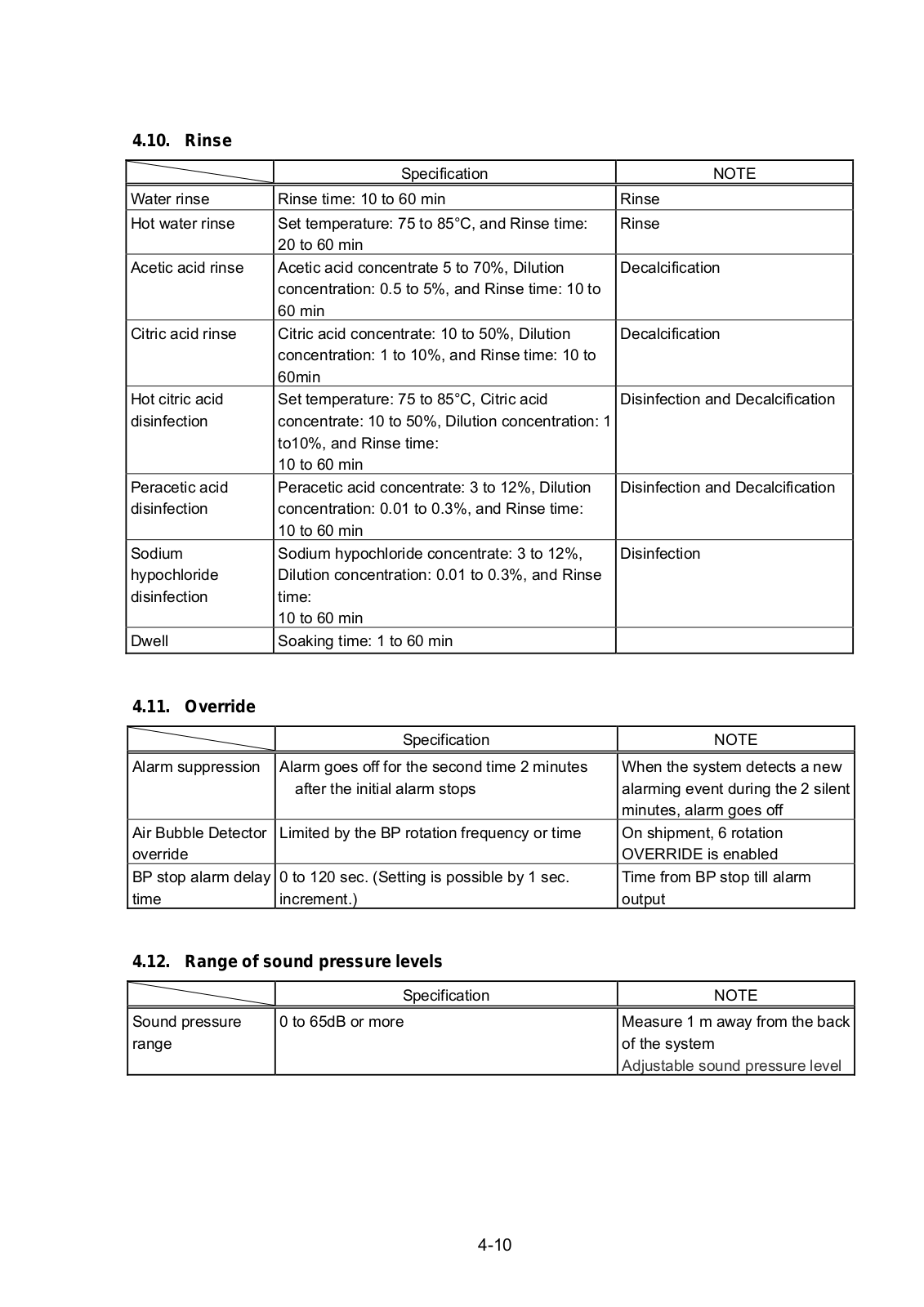
4.10. Rinse


Specification


NOTE


Water rinse

Rinse time: 10 to 60 min


Rinse

Hot water rinse

Set temperature: 75 to 85°C, and Rinse time:


Rinse


20 to 60 min


Acetic acid rinse

Acetic acid concentrate 5 to 70%, Dilution


Decalcification


concentration: 0.5 to 5%, and Rinse time: 10 to


60 min


Citric acid rinse

Citric acid concentrate: 10 to 50%, Dilution


Decalcification


concentration: 1 to 10%, and Rinse time: 10 to


60min


Hot citric acid

Set temperature: 75 to 85°C, Citric acid


Disinfection and Decalcification

disinfection

concentrate: 10 to 50%, Dilution concentration: 1


to10%, and Rinse time:


10 to 60 min


Peracetic acid

Peracetic acid concentrate: 3 to 12%, Dilution


Disinfection and Decalcification

disinfection

concentration: 0.01 to 0.3%, and Rinse time:


10 to 60 min


Sodium

Sodium hypochloride concentrate: 3 to 12%,


Disinfection

hypochloride

Dilution concentration: 0.01 to 0.3%, and Rinse


disinfection

time:


10 to 60 min


Dwell

Soaking time: 1 to 60 min


4.11. Override


Specification

NOTE


Alarm suppression

Alarm goes off for the second time 2 minutes

When the system detects a new


after the initial alarm stops

alarming event during the 2 silent


minutes, alarm goes off

Air Bubble Detector

Limited by the BP rotation frequency or time

On shipment, 6 rotation

override


OVERRIDE is enabled

BP stop alarm delay

0 to 120 sec. (Setting is possible by 1 sec.

Time from BP stop till alarm

time

increment.)

output

4.12. Range of sound pressure levels


Specification

NOTE


Sound pressure

0 to 65dB or more

Measure 1 m away from the back

range


of the system


Adjustable sound pressure level

4-10

Loading...
+ 273 hidden pages