

Page 1

AGB Programming Manual
Version 1.1
April 2, 2001
1999 - 2001 Nintendo of America Inc.
Page 2

AGB Programming Manual
“Confidential”
This document contains confidential and proprietary information
of Nintendo and is also protected under the copyright laws of
the United States and other countries. No part of this document
may be released, distributed, transmitted or reproduced in any
form or by any electronic or mechanical means, including
information storage and retrieval systems, without permission in
writing from Nintendo.
1999 - 2001 Nintendo of America Inc.
TM and are trademarks of Nintendo
©1999 - 2001 Nintendo of America Inc.
2
D.C.N. AGB-06-0001-002B4
Page 3

AGB Programming Manual Introduction
Introduction
2.9" WIDE TFT COLOR
PCM STEREO SOUND
COLOR GRAPHIC EFFECTS
COMPATIBLE FOR CGB
CHARACTER/BITMAP BG
MULTIPLAY COMMUNICATION
32768 COLORS
32BIT RISC CPU 16MHz
Game Boy Advanced (AGB) stresses portability and focuses on 2D rather than 3D image
processing functions, resulting in a cutting-edge portable game device with revolutionary
capabilities.
It provides window-like functions, rotation, scaling, α blending, and fade-in/fade-out
features that can be combined to produce exactly the image representations desired.
Additionally, the bitmap image-rendering function, with its two modes (double buffering
mode for rewriting full-screen images in real time and single buffering mode for stills), can
be used to handle realistic images that are indistinguishable from actual photographs.
The 2.9-inch-wide reflective TFT color LCD screen provides a clear display with little
afterimage.
In addition to Game Boy Color compatible sound, AGB has a PCM stereo sound generator.
Multiple tracks can be played simultaneously by overlapping them using the CPU. L and R
buttons have been added to the Controller. The broader range of control provided also
expands the breadth of game designs possible.
Although AGB uses a 32-bit RISC CPU whose computing performance and data processing
capabilities far surpass those of Game Boy Color, it consumes little power, allowing
approximately 15 hours of continuous play. This is made possible by the inclusion of the various
types of RAM on a single custom chip.
Furthermore, software for AGB can be developed using the C language, minimizing the
cost of development equipment. This favorable development environment and the high
level of freedom of the system configuration allow one to build a profound world of play in
which anyone can become absorbed.
With its extremely high-performance computational and data processing capabilities as a
foundation, AGB provides greater image and sound representation capabilities, making the
pursuit of fun its essential aim.
The purpose of this high level of performance is to bring unique game ideas fully to life.
AGB is an innovation born from experience. While providing backwards compatibility with
the enormous software resources available for the 100 million Game Boy units in use
worldwide, it also breaks new ground for portable game devices.
©1999 - 2001 Nintendo of America Inc.
3 D.C.N. AGB-06-0001-002B4
Page 4

AGB Programming Manual Revision History
Revision History
Version Date Description
0.3.6.2 12/21/1999 -Minor modification. ( Numbering for items: P81,P82,P149),
(Reference to chapter removed)
-Deleted 14.3
0.3.6.3 01/05/2000 -Minor modification.
-Corrected BG Offset Registers diagrams
-Corrected the diagrams of Registers for Setting the Direction
Parameters of BG data.
-Corrected diagram of the Sound 1 Duty Cycle.
-Corrected the name of d05 bit for the DISPCNT Register.
-Added the description of Bit map BG mode.
-Corrected the SIO Timing Chart of Normal Serial Communication.
-Changed the diagrams and descriptions of the Sound Control
Registers.
-Added the formula for calculating the number of OBJs that can
be displayed on 1 line.
0.4.0 01/25/2000
-Changed specifications.
*Changed CPU internal working RAM memory capacity, and
created CPU external working RAM.
*Changed the bit structures of DMA control registers.
*Deleted Infrared Communication functions.
*Created the interrupt IME register, and changed the bit
structures of IE and IF registers.
*Changed the number of colors that can be displayed to 32,768.
*Changed the specifications of Normal Serial Communication
(Bit width, communication speed)
*Changed the specifications of Multi SIO Communication (UART
system).
*Changed the center coordinate of OBJ Rotation to dot
boundary.
*Added UART system communication function.
02/09/2000
0.4.1 02/22/2000
-Added the Complete Block Diagram.
-Modified the description of Direct Sounds, and corrected
register
02/24/2000
02/25/2000
R bit structure.
-Added the PWM sampling cycle control function.
-Changed the method to specify OBJ size.
-Corrected misprints in the communication control register.
0.4.1.1 03/08/2000
03/10/2000
-Added the description of ROM registration data.
-Improved the description of interrupt and multiple interrupt
process.
03/10/2000
-Improved the description of system call and multiple system call
process.
0.4.1.2 04/06/2000 -Added the description of UART system communication.
©1999 - 2001 Nintendo of America Inc.
4 D.C.N. AGB-06-0001-002B4
Page 5

AGB Programming Manual Revision History
Version Date Description
0.4.1.3 05/08/2000
-Corrected [Sound 1 Usage Notes].
-In 1) Normal Communication of Communication Functions,
mentioned not to use a cable.
05/16/2000
-Added the diagram of Multi Player AGB Game Link cable
connection.
05/25/2000
-Changed the diagram in System-Allocated Area in Working RAM,
and deleted “(Tentative)”.
-Revised ROM registration data.
-Corrected the description of internal shift clock of normal SIO
control register.
-Newly added the description of “AGB Game Link cable” in the
chapter of Communication Functions.
-Corrected Overview of Screen Sizes for Text BG Screens in
“Rendering Functions”.
0.4.1.4 05/29/2000 -Added the description for the device type of ROM Registration
Data.
-Corrected “Fault Function” to ”Halt Function.”
-Corrected the diagram of “AGB Game Link cable.”
0.4.1.5 06/01/2000 -Corrected the attributes of timer setting values register from W
to R/W.
-Added one sentence to 1) of 15.2.1. Normal Interrupt and 15.2.2.
Multiple Interrupts respectively.
-Emphasized the prohibition of use of cable for normal SIO
communication.
0.4.1.6 06/26/2000 -Modified the connection diagram of the multi-play cable.
-Added the transition diagram of the multi-play communication
data.
-Modified the description of "16-Bit Multi-play Communication".
0.4.1.7 08/10/2000 -Modified the description of an error flag for the multi=play
control register.
-Modified the description of a valid flag for all the DMA control
registers.
-Added the number of transfer when 0 is set for the DMA word
count register.
0.4.1.8 10/16/2000 -Added cautions to the priority setting of OBJ.
-Added a description and cautions to Sound 1,2,3, and 4.
-Added the description to "Mapping of character data".
-Revised the description in SIOCNT[d14] and [06] of UART
communication register.
-Revised the connection diagram of 16 bit multi-play
communication.
-Added a description to all sound operation modes of the sound
control register.
-Revised the itemized description of Chapter 10 "Sound".
©1999 - 2001 Nintendo of America Inc.
5 D.C.N. AGB-06-0001-002B4
Page 6

AGB Programming Manual Revision History
Version Date Description
1.0 12/01/2000 -Deleted the checksum of ROM registration data and revised the
diagram.
-Revised the diagram for "AGB Game Link Cable" in the "Communication
Function".
-Revised the number of DMG sold from tens of millions to a hundred
million in the introduction of AGB.
-Revised the hours you can play continuously from "about 20 hours" to
"about 15 hours".
-Revised the illustrations of the AGB hardware and the Multi Player AGB
Game Link cable in the multi play communication diagram.
-Added the description of the timing chart for normal SIO communication.
-Added a caution in the DMA valid flag of all the DMA control registers.
-Added a caution in the master start bit of the multi-play control register.
-Revised the multi-play timing chart.
-Revised the memory map for system reserve area in the work RAM.
-Added a caution to "Communication Function".
-Revised the first sentence in "UART Communication". Added "Relation
between Data register, FIFO and Shift register".
-Revised the expression of [Cautions] to a more specific expression
[Cautions for ~~].
-Added a description of X coordinate and Y coordinate for OAM. Added
the diagram to Y coordinate.
-Revised the description of the pre-fetch buffer flag in the Game Pak
memory wait control register.
-Added cautions to the description of the input/output select flag in the R
register of general communication.
1.01 2/01/2001 -Modified the description of pin 31 in the Game Pak bus.
-Revised the cancel conditions for the Stop function in the power-down
mode.
-Added additional descriptions and cautions for the initialization flag of
Sound 1.
1.02 2/13/2001 -Modified the description of "8-Bit/32-Bit Normal Communication Function"
summary in "Communication" chapter.
-Added a paragraph to "Selecting Communication Function" in
"Communication" chapter.
1.04 3/1/2001 -Specified the method to control the OBJ display individually in
the description of the double size flag and the rotation/scaling
flag for OAM attribute 0.
-Added the description of display synchronization DMA to DMA3.
-Added the description of the DMA problem and how to avoid it at the end
of the chapter on DMA.
*Added the restrictions to the description of the repeat flag in DMA3.
*Updated the timing chart and the cable connection diagram for the multiplay communication.
*Revised the description of the normal serial communication cautions.
©1999 - 2001 Nintendo of America Inc.
6 D.C.N. AGB-06-0001-002B4
Page 7

AGB Programming Manual Revision History
1.1 4/2/2001 - Changed the picture in the AGB introduction in the
beginning paragraph.
- Added a caution regarding clearing of IME and IE in the
chapter "Interrupt Control".
- Added additional description of an error flag and ID flag
for multi-play communication.
- Added additional description of communication error flag
of multi-play communication control register.
- Modified the host side example in the description of JOY
bus communication from NUS to DOL.
Added DOL to the abbreviation in "Using This Manual".
- Modified the SIO timing chart for normal serial
communication.
- Revised the number of colors from 256 to 32,768 in the
description of Display Synchronization DMA of DMA3.
- Modified the description of general purpose
communication mode.
- Revised the caution for normal serial communication.
- Revised the caution for communication function.
- Revised the summary of normal serial communication in
the communication function chapter, and added additional
description.
- Added additional description in the caution for the
selection of communication function in the
communication function chapter.
- Emphasized that unless general purpose communication
mode, the cancellation condition SIO for System Call Stop
will not work.
- Changed LPU to LCD controller in system calls Halt and
Stop.
- Deleted the first item in Sound 3 Usage Note.
- Changed the names of following registers according to
header files provided by Nintendo.
--Wait Control--
204h WSCNT àà WAITCNT
--Color Special Effects--
050h BLDMOD àà BLDCNT
052h COLEV
054h COLY
àà BLDALPHA
àà BLDY
--Sound Related --
080h~ SGCNT0_(L H) àà SOUNDCNT_(L H) ** Combined multiple names
084h SGCNT1 àà SOUNDCNT_X
088h SG_BIAS
060h~ SG10_(L H)
064h SG11 àà SOUND1CNT_X
068h SG20
06Ch SG21
àà SOUNDBIAS
àà SOUND1CNT_(L H) **
àà SOUND2CNT_L
àà SOUND2CNT_H
©1999 - 2001 Nintendo of America Inc.
7 D.C.N. AGB-06-0001-002B4
Page 8

AGB Programming Manual Revision History
074h SG31 àà SOUND3CNT_X
078h SG40 àà SOUND4CNT_L
07Ch SG41 àà SOUND4CNT_H
090h~ SGWR(0-3)_L àà WAVE_RAM(0-3)_L **
092h~ SGWR(0-3)_H àà WAVE_RAM(0-3)_H **
0A0h~ SG_FIFOA_(L H) àà FIFO_A_(L H) **
0A4h~ SG_FIFOB_(L H) àà FIFO_B_(L H) **
--DMA Related --
0B0h~ DM(0-3)SAD_L àà DMA(0-3)SAD_L **
0B2h~ DM(0-3)SAD_H àà DMA(0-3)SAD_H **
0B4h~ DM(0-3)DAD_L àà DMA(0-3)DAD_L **
0B6h~ DM(0-3)DAD_H àà DMA(0-3)DAD_H **
0B8h~ DM(0-3)CNT_L àà DMA(0-3)CNT_L **
0Bah~ DM(0-3)CNT_H àà DMA(0-3)CNT_H **
--Timer Related --
100h~ TM(0-3)D àà TM(0-3)CNT_L **
102h~ TM(0-3)CNT àà TM(0-3)CNT_H **
--Communication Related --
134h R àà RCNT
128h SCCNT_L àà SIOCNT
12Ah SCCNT_H àà SIODATA8 (Normal serial, UART communication)
SIOMLT_SEND (Multi-play communication)
120h SCD0 àà SIODATA32_L (Normal serial communication)
SIOMULTI0 (Multi-play communication)
122h SCD1 àà SIODATA32_H (Normal serial communication)
SIOMULTI1 (Multi-play communication)
124h~ SCD(2 3) àà SIOMULTI(2 3) **
140h HS_CTRL àà JOYCNT
158h JSTAT àà JOYSTAT
150h~ JOYRE_(L H) àà JOY_RECV_(L H) **
154h~ JOYTR_(L H) àà JOYTRANS_(L H) **
--Key Related --
130h P1 àà KEYINPUT
132h P1CNT àà KEYCNT
©1999 - 2001 Nintendo of America Inc.
8 D.C.N. AGB-06-0001-002B4
Page 9

AGB Programming Manual Table of Contents
Table of Contents
1 AGB SYSTEM .....................................................................................13
1.1 SYSTEM OVERVIEW.....................................................................................................13
2 SYSTEM CONFIGURATION..............................................................15
2.1 CPU BLOCK DIAGRAM...............................................................................................15
2.2 COMPLETE BLOCK DIAGRAM .....................................................................................16
2.3 MEMORY CONFIGURATION AND ACCESS WIDTH .......................................................17
2.4 LITTLE-ENDIAN............................................................................................................17
3 AGB MEMORY....................................................................................18
3.1 OVERALL MEMORY MAP .............................................................................................18
3.2 MEMORY CONFIGURATION..........................................................................................19
3.2.1 AGB Internal Memory .................................................................................................19
3.2.2 Game Pak Memory ....................................................................................................20
3.3 GAME PAK MEMORY WAIT CONTROL........................................................................21
3.3.1 Access Timing ...........................................................................................................23
3.3.2 Game Pak Bus ..........................................................................................................24
4 LCD.......................................................................................................25
4.1 LCD STATUS...............................................................................................................26
4.1.1 V Counter ..................................................................................................................26
4.1.2 General LCD Status ...................................................................................................27
5 IMAGE SYSTEM...............................................................................29
5.1 BG MODES ..................................................................................................................31
5.1.1 Details of BG Modes ..................................................................................................31
5.1.2 VRAM Memory Map ...................................................................................................32
6 RENDERING FUNCTION S...............................................................33
6.1 CHARACTER MODE BG (BG MODES 0-2)..................................................................33
6.1.1 BG Control ................................................................................................................33
6.1.2 Mosaic Size..............................................................................................................39
6.1.3 VRAM Address Mapping of BG Data............................................................................40
6.1.4 Character Data Format ..............................................................................................42
6.1.5 BG Screen Data Format .............................................................................................43
6.1.6 BG Screen Data Address Mapping for the LCD Screen ..................................................45
6.1.7 BG Rotation and Scaling Features...............................................................................49
6.1.8 BG Scrolling..............................................................................................................52
©1999 - 2001 Nintendo of America Inc.
9 D.C.N. AGB-06-0001-002B4
Page 10

AGB Programming Manual Table of Contents
6.2 BITMAP MODE BGS (BG MODES 3-5).......................................................................53
6.2.1 BG Control ................................................................................................................53
6.2.2 BG Rotation/Scaling ...................................................................................................54
6.2.3 Pixel Data.................................................................................................................54
6.2.4 Pixel Data Address Mapping for the LCD Screen...........................................................55
6.3 OBJ (OBJECT).............................................................................................................58
6.3.1 OBJ Function Overview.............................................................................................58
6.3.2 Character Data Mapping .............................................................................................60
6.3.3 OAM .........................................................................................................................62
6.3.4 OBJ Rotation/Scaling Feature .....................................................................................70
6.4 DISPLAY PRIORITY OF OBJ AND BG.........................................................................72
7. COLOR PALETTES...........................................................................73
7.1 COLOR PALETTE OVERVIEW ......................................................................................73
7.2 COLOR PALETTE RAM...............................................................................................74
7.3 COLOR DATA FORMAT................................................................................................76
8 WINDOW FEATURE............................................................................77
8.1 WINDOW POSITION SETTING......................................................................................77
8.2 WINDOW CONTROL.....................................................................................................78
9 COLOR SPECIAL EFFECTS..........................................................80
9.1 SELECTION OF COLOR SPECIAL EFFECTS ................................................................80
9.2 COLOR SPECIAL EFFECTS PROCESSING...................................................................82
10 SOUND ...............................................................................................84
10.1 SOUND BLOCK DIAGRAM .........................................................................................84
10.2 DIRECT SOUNDS A AND B........................................................................................85
10.3 SOUND 1....................................................................................................................87
10.4 SOUND 2....................................................................................................................91
10.5 SOUND 3....................................................................................................................93
10.6 SOUND 4....................................................................................................................97
10.7 SOUND CONTROL....................................................................................................100
10.8 SOUND PWM CONTROL.........................................................................................104
11 TIMER ...............................................................................................106
©1999 - 2001 Nintendo of America Inc.
10 D.C.N. AGB-06-0001-002B4
Page 11

AGB Programming Manual Table of Contents
12 DMA TRANSFER............................................................................108
12.1 DMA 0.....................................................................................................................109
12.2 DMA 1 AND 2..........................................................................................................113
12.3 DMA 3 ....................................................................................................................117
12.4 DMA 4 ....................................................................................................................122
13 COMMUNICATION FUNCTIONS ..................................................125
13.1 8-BIT/32-BIT NORMAL SERIAL COMMUNICATION ................................................128
13.2 16-BIT MULTI-PLAYER COMMUNICATION ..............................................................134
13.3 UART COMMUNICATION FUNCTIONS ....................................................................142
13.4 GENERAL PURPOSE COMMUNICATION...................................................................148
13.5 JOY BUS COMMUNICATION ...................................................................................150
13.6 AGB GAME LINK CABLE.........................................................................................154
14 KEY INPUT ......................................................................................155
14.1 KEY STATUS............................................................................................................155
14.2 KEY INTERRUPT CONTROL......................................................................................155
14.2.1 Interrupt Conditions ...................................................................................................156
15 INTERRUPT CONTROL.................................................................157
15.1 SYSTEM-ALLOCATED AREA IN WORK RAM..........................................................159
15.2 INTERRUPT OPERATION...........................................................................................160
15.2.1 Normal Interrupt ........................................................................................................160
15.2.2 Multiple Interrupts .....................................................................................................161
16 POWER-DOWN FUNCTIONS ........................................................163
16.1 STOP FUNCTION......................................................................................................163
16.2 HALT FUNCTION......................................................................................................164
17 AGB SYSTEM CALLS...................................................................165
17.1 SYSTEM CALL OPERATION.....................................................................................165
17.1.1 Normal Calls............................................................................................................165
17.1.2 Multiple Calls...........................................................................................................167
18 ROM REGISTRATION DATA........................................................170
©1999 - 2001 Nintendo of America Inc.
11 D.C.N. AGB-06-0001-002B4
Page 12
AGB Programming Manual Using This Manual
Using This Manual
Important terms and symbols used in this manual are defined below.
1. Terms
The term “user” in this manual refers to the software developer, not to the general consumer.
Bit lengths in this manual are expressed as follows.
Bit Length Term Used
8 bits byte
16 bits half-word
32 bits word
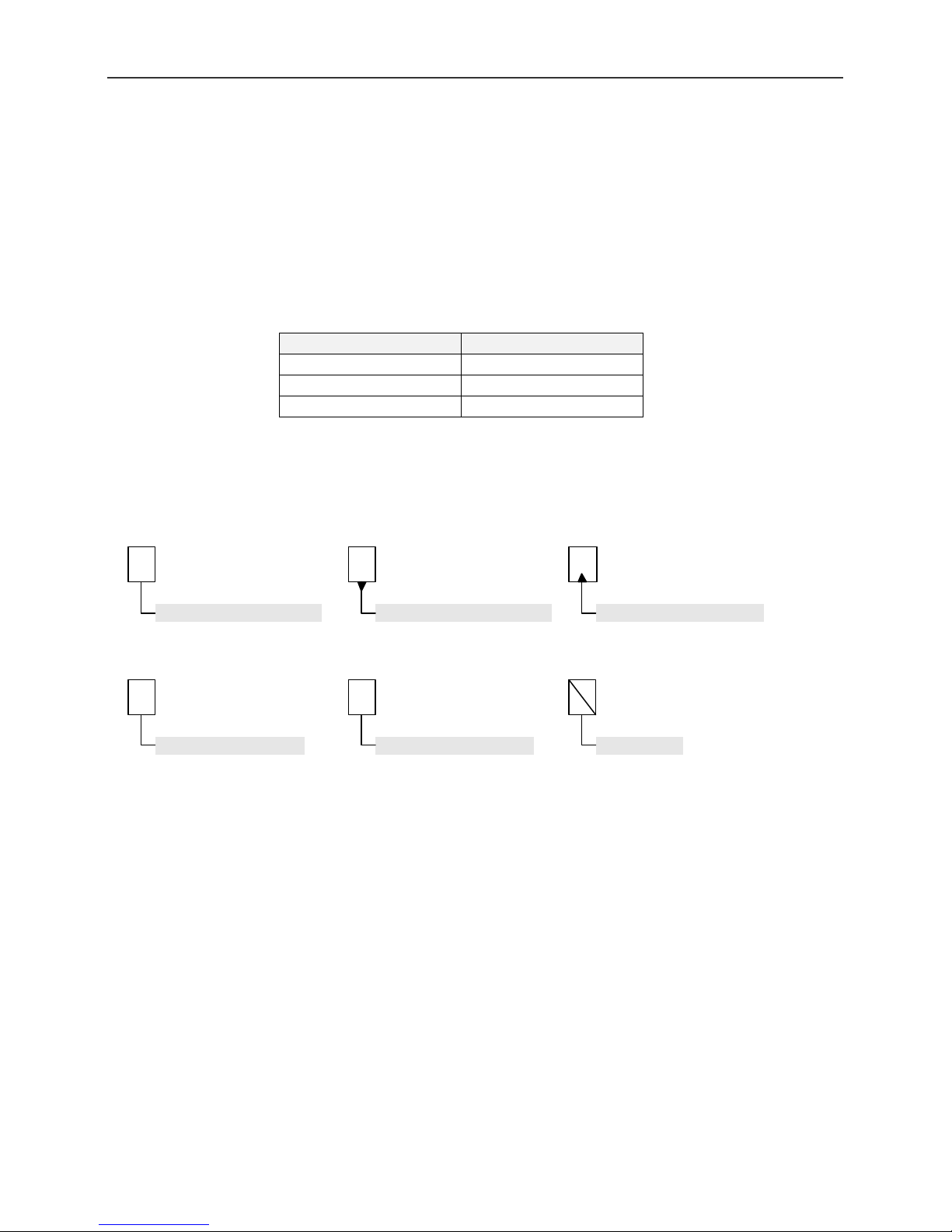
2. Symbols
The attributes of bits used in bit operations are represented as follows.
Read/write bit
A readable and writable bit.
1
Fixed-value bit
Must be set to a
specified fixed value.
Read-only bit
A bit that is readable but not
writable.
*
Unrestricted bit
Can be set to either 0 or 1.
Write-only bit
A bit that is not readable but
is writable.
Not used
3. Abbreviations
Nintendo's game hardware is abbreviated as follows:
Ø DMG (Game Boy)
Ø CGB (Game Boy Color)
Ø AGB (Game Boy Advance)
Ø DOL (Nintendo GameCube)
©1999 - 2001 Nintendo of America Inc.
12 D.C.N. AGB-06-0001-002B4
Page 13

AGB Programming Manual AGB System
1 AGB System
1.1 System Overview
AGB is a portable game device that maintains downward compatibility with Game Boy
Color (CGB) and provides higher performance.
AGB’s 2.9-inch-wide reflective TFT color LCD and 32-bit RISC CPU enable production
of games that match or surpass the Super Nintendo Entertainment System (Super
NES) in performance.
AGB CPU
32-bit RISC CPU (ARM7TDMI)/16.78 MHz
Downward Compatibility with CGB
Integral 8-bit CISC CPU for compatibility
(However, it cannot operate at the same time as the AGB CPU.)
Memory
System ROM 16 Kbytes (and 2 Kbytes for CGB System ROM)
Working RAM 32 Kbytes + CPU External 256 Kbytes (2 wait)
VRAM 96 Kbytes
OAM 64 bits x 128
Palette RAM 16 bits x 512 (256 colors for OBJ ;
256 colors for BG)
Game Pak
memory
Up to 32 MB: mask ROM or flash memory
(&EEPROM)
+
Up to 512 Kbits: SRAM or flash memory
Display
240 x 160 x RGB dots
32,768 colors simultaneously displayable
Special effects features (rotation/scaling, α blending, fade-in/fade-out, and mosaic)
4 image system modes
Operation
Operating keys (A, B, L, R, START, SELECT, and Control Pad)
Sound
4 sounds (corresponding to CGB sounds) + 2 CPU direct sounds (PCM format)
Communication
Serial communication (8 bit/32 bit, UART, Multi-player, General-purpose, JOY Bus)
©1999 - 2001 Nintendo of America Inc.
13 D.C.N. AGB-06-0001-002B4
Page 14

AGB Programming Manual AGB System
Game Pak
Like DMG and CGB, AGB is equipped with a 32-pin connector for Game Pak
connection. When a Game Pak is inserted, AGB automatically detects its type and
switches to either CGB or AGB mode.
The following Game Paks operate on the AGB system.
1. DMG Game Paks, DMG/CGB dual mode Game Paks, and CGB dedicated Game
Paks
2. AGB dedicated Game Paks(Game Paks that only function with AGB)
©1999 - 2001 Nintendo of America Inc.
14 D.C.N. AGB-06-0001-002B4
Page 15

AGB Programming Manual System Configuration
2 System Configuration
2.1 CPU Block Diagram
Game Pak
CPU
16
Game Pak I/F
(Prefetch Buffer)
ARM7TDMI
CPU
(16.78MHz)
32
VRAM_A
(64KByte)
16
INT
Control
ROM
(16KByte)
WRAM
(32KByte)
EXT. WRAM
(256KByte)
DMAC
(4ch)
Timer
(4ch)
SIO
SOUND(CGB
compatible + PWM)
KEY
Control
32
R:8/16/32
W:8/16/32
32
R:8/16/32
32
R:8/16/32
W:8/16/32
16(2 Wait)
R:8/16/32
W:8/16/32
32
R:8/16/32
W:8/16/32
32
R:8/16/32
W:8/16/32
32
R:8/16/32
W:8/16/32
32
32
32
16
R:16/32
W:16/32
32
R:16/32
W:16/32
32
R:16/32
W:16/32
16
R:16/32
W:16/32
32
R:8/16/32
W:8/16/32
BG Processing Circuit
16
VRAM_B
(16KByte)
16
16
VRAM_C
(16KByte)
16
OBJ Processing Circuit
OAM
(64bit x 128)
16
Priority Evaluation Circuit
16
Palette RAM
(16bit x 512)
16
Special Color Processing Circuit
RGB(5:5:5)
16
16
Bitmap
Mode
16
* "R:8/16/32" and "W:8/16/32" mean that you can
access an area of 8bits/16bits/32bits when reading
and writing, respectively.
©1999 - 2001 Nintendo of America Inc.
LCD Unit
15 D.C.N. AGB-06-0001-002B4
Page 16

AGB Programming Manual System Configuration
2.2 Complete Block Diagram
AGB Unit
LCD Module
External
Unit
Infrared
Communi
-cation
Adaptor,
etc.
Regulator IC
CPU External WRAM
256KByte
16bit Bus
6Pin-EXP
SIO
8/32bit SIO
General Purpose
Communi-
cation
Multi-SIO
UART
JOY
Sound
Volume
Sound
Amp
Port
2wait
2.9"Reflective TFT Color LCD
240 x 160 x RGB Dot
32,768 Colors Displayable
LCD Driver
CPU
RGB
LCD Controller
VRAM
98KByte
16bit Bus
ARM7TDMI
CPU Internal WRAM
32KByte
32bit Bus
AGB System ROM
16KByte
32bit Bus
CGB System ROM
Peripheral Circuit
(SOUND, DMA, TIMER, I/O, etc)
Prefetch Buffer
16bit x 8
LCD DriverLCD Driver LCD Driver
AGB 32bit
CPU Core
CGB 8bit
CPU Core
2KB
DC-DC Converter
and Regulator
Power Switch
AA Alkaline Battery
AA Alkaline Battery
3.3V/5V
Voltage
Detection
Circuit
Controller
L
SELECT START
13.6V5V3.3V2.5V-15V
R
A
B
Headphone
Jack
Gane Pak
©1999 - 2001 Nintendo of America Inc.
4.194MHz
(System 16.78MHz)
Speaker
General Purpose
Bus Memory Space
64KByte Max.
AD Bus Memory
Space
32MByte Max.
Power 3.3V
AGB Game Pak(AGB Only)
5V(DMG/CGB)3.3V(AGB)
Game Pak Shape
Detection Switch
General Purpose Bus
Switch Between AD Bus/
Game Pak Power
3.3V(AGB)/5V(DMG/CGB)
General Purpose Bus
Memory Space
32KByte Max.
Power 5V
DMG/CGB Game Pak
16 D.C.N. AGB-06-0001-002B4
Page 17

AGB Programming Manual System Configuration
2.3 Memory Configuration and Access Width
Memory Type
Bus
Width
Read
Width
DMA CPU
Write
Width
Read
Width
Write
Width
OAM 32 16/32 16/32 16/32 16/32
Palette RAM 16 16/32 16/32 16/32 16/32
VRAM 16 16/32 16/32 16/32 16/32
CPU Internal Working RAM 32 16/32 16/32 8/16/32 8/16/32
CPU External Working RAM 16 16/32 16/32 8/16/32 8/16/32
Internal registers 32 16/32 16/32 8/16/32 8/16/32
Game Pak ROM
16 16/32 16/32 8/16/32 16/32
(Mask ROM, Flash Memory)
Game Pak RAM
8 -- -- 8 8
(SRAM, Flash Memory)
Good execution efficiency is obtained when programs that operate from the Game Pak
use 16-bit instructions (16-bit compiler), and those that operate from CPU Internal
Working RAM use 32-bit instructions (32-bit compiler).
2.4 Little- Endian
In the AGB CPU, memory addresses are allocated in 8-bit increments, and littleendian format is used in implementing the 8-, 16-, and 32-bit access widths.
Memory Register
0003h
0002h
0001h
0000h
©1999 - 2001 Nintendo of America Inc.
D
C
B
A
d31 d24 d23 d16 d15 d08 d07 d00
ABCD
17 D.C.N. AGB-06-0001-002B4
Page 18

AGB Programming Manual AGB Memory
3 AGB Memory
3.1 Overall Memory Map
The following is the overall memory map of the AGB system.
0FFFFFFFh
Game Pak Memory
AGB Internal
Memory
0E00FFFFh
0E000000h
0DFFFFFFh
0C000000h
0BFFFFFFh
0A000000h
09FFFFFFh
08000000h
070003FFh
07000000h
Game Pak RAM
(0 - 512 Kbits)
Game Pak ROM
Wait State 2
(32 MB)
Game Pak ROM
Wait State 1
(32 MB)
Game Pak ROM
Wait State 0
(32 MB)
OAM
(1 Kbyte)
Images
Flash Memory
(1 Mbit)
Mask ROM
(255 Mbits)
Flash Memory
(1 Mbit)
Mask ROM
(255 Mbits)
Flash Memory
(1 Mbit)
Mask ROM
(255 Mbits)
06017FFFh
06000000h
050003FFh
05000000h
04000000h
03007FFFh
03000000h
0203FFFFh
02000000h
00003FFFh
00000000h
VRAM
(96 Kbytes)
Palette RAM
(1 Kbyte)
I/O, Registers
CPU Internal Working RAM
(32 Kbytes)
CPU External Working RAM
(256 Kbytes)
System ROM
(16 Kbytes)
ROM
RAM
Unused Area
Image Area
©1999 - 2001 Nintendo of America Inc.
18 D.C.N. AGB-06-0001-002B4
Page 19

AGB Programming Manual AGB Memory
3.2 Memory Configuration
In broad terms, the area 00000000h-07FFFFFFh is allocated as AGB internal memory,
and 08000000-0EFFFFFFh is allocated as Game Pak memory.
3.2.1 AGB Internal Memory
1) System ROM
The 16 KBytes from 000000000h is the system ROM.
Various types of System Calls can be used.
2) CPU External Working RAM
The 256 Kbytes from 02000000h is CPU External Working RAM. Its
specifications are 2 Wait 16 bit Bus.
3) CPU Internal Working RAM
The 32 Kbytes from 03000000h is CPU Internal Working RAM. It is used to
store programs and data.
4) I/O and Registers
This area is used for various registers.
5) Palette RAM
The 1 Kbyte from 05000000h is palette RAM. It is used to assign palette
colors.
6) VRAM
The 96 Kbytes from 06000000h is the VRAM area. This area is for BG and
OBJ data.
7) OAM
The 1 Kbyte from 07000000h is Object Attribute Memory (OAM). It holds
the objects to be displayed and their attributes.
©1999 - 2001 Nintendo of America Inc.
19 D.C.N. AGB-06-0001-002B4
Page 20

AGB Programming Manual AGB Memory
3.2.2 Game Pak Memory
1) Game Pak ROM
Three 32 MB Game Pak ROM spaces are allocated to the area beginning
from 08000000h.
The access speed of each of these spaces can be set individually. Thus,
they are named Wait State 0, Wait State 1, and Wait State 2.
This specification enables memory of varying access speeds in Game Pak
ROM to be accessed optimally.
The base addresses of the 3 spaces are 08000000h for Wait State 0,
0A000000h for Wait State 1, and 0C000000h for Wait State 2.
In addition, the upper 1 Mbit of each space is allocated as flash memory.
This area is used primarily for saving data.
2) Game Pak RAM
The area beginning from 0E000000h is the Game Pak RAM area. Up to
512 Kbits of SRAM or Flash Memory can be stored here. However, it is an
8 bit data bus. Due to the specifications, any Game Pak device other than
ROM must be accessed using Nintendo's library.
©1999 - 2001 Nintendo of America Inc.
20 D.C.N. AGB-06-0001-002B4
Page 21

AGB Programming Manual AGB Memory
Initial
3.3 Game Pak Memory Wait Control
Although the 32 MB Game Pak memory space is mapped to the area from 08000000h
onward, the 32 MB spaces beginning from 0A000000h and 0C000000h are images of
the 32 MB space that starts at 08000000h.
These images enable memory to be used according to the access speed of the Game
Pak memory (1-4 wait cycles).
Address Register Attributes
15 14 13 12 11 10 09 08 07 06 05 04 03 02 01 00
WAITCNT204h 0000hR/W
Game Pak RAM
Wait Control
Wait State 0
Wait Control
Wait State 1
Wait Control
Wait State 2
Wait Control
PHI Terminal Output Control
00: No Output
01: 4.19 MHz clock
10: 8.38 MHz clock
11: 16.76 MHZ clock
Prefetch Buffer Flag
0: Disabled
1: Enabled
Game Pak Type Flag
Value
WAITCNT [d15] Game Pak Type Flag
The System ROM uses this.
WAITCNT [d14] Prefetch Buffer Flag
When the Prefetch Buffer Flag is enabled and there is some free space,
the Prefetch Buffer takes control of the Game Pak Bus during the time
when the CPU is not using it, and reads Game Pak ROM data repeatedly.
When the CPU tries to read instructions from the Game Pak and if it hits
the Prefetch Buffer, the fetch is completed with no wait in respect to the
CPU. If there is no hit, the fetch is done from the Game Pak ROM and
there is a wait based on the set wait state.
©1999 - 2001 Nintendo of America Inc.
21 D.C.N. AGB-06-0001-002B4
Page 22

AGB Programming Manual AGB Memory
If the Prefetch Buffer Flag is disabled, the fetch is done from the Game Pak
ROM. There is a wait based on the wait state associated with the fetch
instruction to the Game Pak ROM in respect to the CPU.
WAITCNT [d12 - 11] PHI Terminal Output Control
Controls the output from the PHI terminal. This should always be set to
00(No Output).
WAITCNT [d10 - 08],[d07 - 05],[d04 - 02] Wait State Wait Control
Individual wait cycles for each of the three areas(Wait States 0-2) that
occur in Game Pak ROM can be set. The relation between the wait control
settings and wait cycles is as follows. Use the appropriate settings for the
device you are using.
Wait Cycles
Wait Control Value
1st Access
Wait State0Wait State1Wait State
2nd Access
2
000 4 2 4 8
001 3 2 4 8
010 2 2 4 8
011 8 2 4 8
100 4 1 1 1
101 3 1 1 1
110 2 1 1 1
111 8 1 1 1
After executing the System ROM (when the User Program is started) the Wait
Control Value is 000. In the Game Pak Mask ROM used with the actual
manufactured product, the specifications are 1st Access/3 Wait, 2nd Access/1 Wait.
In this case, set the Wait Control Value to 101.
WAITCNT [d01 - 00] Game Pak RAM Wait Control
Wait cycles for the Game Pak RAM can be set. The relation between the
wait control settings and wait cycles is as follows. Use the appropriate
settings for the device you are using.
Wait Control Value
©1999 - 2001 Nintendo of America Inc.
Wait Cycles
00 4
01 3
10 2
11 8
22 D.C.N. AGB-06-0001-002B4
Page 23

AGB Programming Manual AGB Memory
3.3.1 Access Timing
The following timing charts illustrate Game Pak ROM access with 3 wait
cycles on the first access and 1 wait cycle on the second.
1) Sequential Access
System Clock
16.78 MHz
Wait Cycles
AD Bus
2) Random Access
System Clock
16.78 MHz
Wait Cycles
AD Bus
wait wait wait
Address Data Data
1st Access
(3 wait cycles)
wait wait wait
Address Data
wait
2nd Access
(1 wait cycle)
wait
Address
wait
Data
3rd Access
(1 wait cycle)
waitwait
Data
©1999 - 2001 Nintendo of America Inc.
1st Access
(3 wait cycles)
1st Access
(3 wait cycles)
23 D.C.N. AGB-06-0001-002B4
Page 24

AGB Programming Manual AGB Memory
3.3.2 Game Pak Bus
The Game Pak bus has a total of 32 terminals, which are described in the following table.
No.
Game Pak ROM Access Game Pak RAM Access
Terminal Use Terminal Use
1 VDD(3.3V) VDD(3.3V)
2 PHI PHI
3 /WR Write Flag /WR Write Flag
4 /RD Read Flag /RD Read Flag
5 /CS ROM Chip Selection /CS
6 AD0 A0
7 AD1 A1
8 AD2 A2
9 AD3 A3
10 AD4 A4
11 AD5 A5
12 AD6 A6
13 AD7 A7
14 AD8 A8
15 AD9 A9
Terminals used for
both address(lower)
and data
Address
16 AD10 A10
17 AD11 A11
18 AD12 A12
19 AD13 A13
20 AD14 A14
21 AD15
A15
22 A16 D0
23 A17 D1
24 A18 D2
25 A19 D3
26 A20 D4
Address(upper)
Data
27 A21 D5
28 A22 D6
29 A23
D7
30 /CS2 /CS2 RAM Chip Selection
31
IREQ and
DREQ
Terminal used for IREQ
and DREQ
IREQ and
DREQ
Terminal used for IREQ
and DREQ
32 GND GND
©1999 - 2001 Nintendo of America Inc.
24 D.C.N. AGB-06-0001-002B4
Page 25

AGB Programming Manual LCD
4 LCD
AGB uses a 2.9-inch-wide reflective TFT color LCD screen.
The vertical blanking interval of AGB is longer than that of DMG and CGB, and its horizontal
blanking interval is fixed.
308 dots
160 lines
228 lines
(4.994ms)
Item Value Interval
Display
screen size
Number of dots per
horizontal line
Number of
horizontal lines
Total number
of dots
Number of dots per
horizontal line
Number of
horizontal lines
Blanking Number of dots per
horizontal blank
Number of
horizontal lines per
vertical blank
Scanning
cycle
H interval frequency 13.618 KHz
V interval frequency 59.727 Hz 16.743 ms
240 dots
Display
Screen
Vertical
Blank
240 dots
57.221 µs
160 lines 11.749 ms
308 dots
73.433 µs
228 lines 16.743 ms
68 dots
16.212 µs
68 lines 4.994 ms
73.433 µs
(16.212µs)
Horizontal
Blank
©1999 - 2001 Nintendo of America Inc.
25 D.C.N. AGB-06-0001-002B4
Page 26

AGB Programming Manual LCD
4.1 LCD Status
4.1.1 V Counter
The VCOUNT register can be used to read which of the total of 228 LCD
lines (see previous figure) is currently being rendered.
Address Register
006h
VCOUNT
15 14 13 12 11 10 09 08 07 06 05 04 03 02 01 00
V counter value
0-227
Attributes Initial Value
R
0000h
A value of 0-227 is read.
A value of 0-159 indicates that rendering is in progress; a value of 160-227
indicates a vertical blanking interval.
©1999 - 2001 Nintendo of America Inc.
26 D.C.N. AGB-06-0001-002B4
Page 27

AGB Programming Manual LCD
4.1.2 General LCD Status
General LCD status information can be read from bits 0-5 of the
DISPSTAT register.
In addition, 3 types of interrupt requests can be generated by the LCD
controller.
Address Register
004h
DISPSTAT
DISPSTAT [d15-08] V Count Setting
15 14 13 12 11 10 09 08 07 06 05 04 03 02 01 00
V-Blank Status
V count setting
0-227
V-Blank Interrupt Request Enable Flag
0: Disable
1: Enable
H-Blank Interrupt Request Enable Flag
0: Disable
1: Enable
V Counter Match Interrupt Request Enable Flag
0: Disable
1: Enable
0: Outside V-blank interval
1: During V-blank interval
H-Blank Status
0: Outside H-blank interval
1: During H-blank interval
V Counter Evaluation
0: V counter non-match
1: V counter match
Attributes
R/W
Initial Value
0000h
Can be used to set the value used for V counter evaluation and V counter
match interrupts. The range for this setting is 0-227.
DISPSTAT [d05] V Counter Match Interrupt Request Enable Flag
Allows an interrupt request to be generated when the value of the V counter
setting and the value of the line actually rendered (VCOUNT register value)
agree.
DISPSTAT [d04] H-Blank Interrupt Request Enable Flag
Allows an interrupt request to be generated during horizontal blanking.
DISPSTAT [d03] V-Blank Interrupt Request Enable Flag
Allows an interrupt request to be generated during vertical blanking.
©1999 - 2001 Nintendo of America Inc.
27 D.C.N. AGB-06-0001-002B4
Page 28

AGB Programming Manual LCD
DISPSTAT [d02] V Counter Evaluation
Flag indicating whether the V count setting and the V count register value
match. It is set while they match and automatically reset when they no
longer match.
DISPSTAT [d01] H-Blank Status
Can check whether a horizontal blanking interval is currently in effect.
DISPSTAT [d00] V-Blank Status
Can check whether a vertical blanking interval is currently in effect.
©1999 - 2001 Nintendo of America Inc.
28 D.C.N. AGB-06-0001-002B4
Page 29

AGB Programming Manual Image System
5 Image System
AGB can use different image systems depending on the purpose of the software.
These display-related items are changed mainly using the DISPCNT register.
Address Register Attributes Initial Value
DISPCNT0000h 0080hR/W
15 14 13 12 11 10 09 08 07 06 05 04 03 02 01 00
OBJBG3BG2BG1BG0
BG Mode
0-5
(CGB Mode)
Display Frame Selection
0: Frame buffer 0
1: Frame buffer 1
H-Blank Interval OBJ Processing Flag
0: Enable(OBJ Processing of all H-Line
Intervals)
1: Disable(OBJ Processing of H-Line
Display Intervals Only)
OBJ Character VRAM Mapping Format
0: 2-dimensional
1: 1-dimensional
Forced Blank
0: Disable
1: Enable
Individual Screens Display
0: OFF
1: ON
Window 0 Display Flag
Window 1 Display Flag
OBJ Window Display Flag
DISPCNT [d15] OBJ Window Display Flag
Master flag that controls whether the OBJ window is displayed.
For information on the OBJ window, see section “6.3, OBJ (Object)”.
DISPCNT [d14][d13] Display Flags for Windows 0 and 1
Master flag that controls whether windows 0 and 1 are displayed.
For information on windows, see “Chapter 8, Window Feature”.
DISPCNT [d12-08] Individual Screens Display Flag
Allows individual control of whether BG0, BG1, BG2, BG3, and OBJ,
respectively, are displayed.
©1999 - 2001 Nintendo of America Inc.
29 D.C.N. AGB-06-0001-002B4
Page 30

AGB Programming Manual Image System
DISPCNT [d07] Forced Blank
Setting this bit causes the CPU to forcibly halt operation of the image
processing circuit, allowing access to VRAM, color palette RAM, OAM, and
the internal registers. The LCD screen displays white during a forced
blank. However, the internal HV synchronous counter continues to operate
even during a forced blank. When the internal HV synchronous counter
cancels a forced blank during a display period, the display begins from the
beginning, following the display of three vertical lines.
DISPCNT [d06] OBJ Character VRAM Mapping Format
Specifies the VRAM mapping format for an OBJ character.
A setting of 0 causes the OBJ character to be handled in memory mapped
2-dimensional. A setting of 1 causes the OBJ character to be handled in
memory mapped 1-dimensional.
For information on OBJ character VRAM mapping formats, see section
6.3.2, Character Data Mapping.
DISPCNT [d05] H-Blank Interval OBJ Processing Flag
A setting of 0 executes OBJ Render Processing with all H-Line
intervals(including H-Blank intervals).
A setting of 1 executes OBJ Render Processing with the display intervals
only and not for H-Blank intervals. Thus, when the user accesses OAM or
OBJ VRAM during an H-Blank interval, this bit needs to be set. However,
also in this situation, maximum OBJ display performance cannot be
obtained.
DISPCNT [d04] Display Frame Selection
When rendering in bitmap format in a mode in which there are 2 frame
buffers (BG modes 4 and 5), this bit allows selection of one of the frame
buffers for rendering. A setting of 0 selects the contents of frame buffer 0
for rendering; a setting of 1 selects the contents of frame buffer 1 for
rendering.
DISPCNT [d03] (CGB Mode)
AGB is equipped with 2 CPUs. In AGB mode, a 32-bit RISC CPU starts,
and in CGB mode, an 8-bit CISC CPU starts. Because this bit is
controlled by the system, it cannot be accessed by the user.
DISPCNT [d02-00] BG Mode
Selects the BG mode from a range of 0-5.
For more information on BG modes, see the following section.
©1999 - 2001 Nintendo of America Inc.
30 D.C.N. AGB-06-0001-002B4
Page 31

AGB Programming Manual Image System
5.1 BG Modes
5.1.1 Details of BG Modes
In AGB, changing the BG mode allows character format and bitmap format
to be used selectively, as appropriate.
In modes 0, 1, and 2, rendering to the LCD screen is performed in a
character format suitable for the game.
In modes 3, 4, and 5, rendering to the LCD screen is performed in bitmap
format.
Character Format BG Screen
BG Mode
0 No 4
1
2 Yes 2
BG Mode
3 Yes 1 240 x 160 1 32,768 O X O O O O
4 Yes 1 240 x160 2 256 O X O O O O
Rotation/
Scaling
No 2
Yes 1
Bitmap Format BG Screen Features
Rotation/
Scaling
No. of
Screens
No. of
Screens
Size
256 x 256
to
512 x 512
256 x 256
to
512 x 512
128 x 128
to
1024 x 1024
128 x 128
to
1024 x 1024
Size
Number of
Characters
Specifiable
1024
1024
256
256
Frame
Memory
Number of Colors/
Palettes
16 / 16
256 / 1
16 / 16
256 / 1
256 / 1 O X O O O O
256 / 1 O X O O O O
No. of Colors
Features
*1 *2 *3 *4 *5 *6
O O O O O O
O O O O O O
*1 *2 *3 *4 *5 *6
5 Yes 1 160 x 128 2 32,768 O X O O O O
Features *1 HV Scroll (individual screens) *4 Semitransparent(16 levels)
*2 HV Flip (individual characters) *5 Fade-in/Fade-out
*3 Mosaic (16 levels) *6 Screen priority specification (2 bits)
[Note]
In mode 3, one frame memory is available that can display 32,768 colors, which is suitable for
rendering still images. Modes 4 and 5 allow double buffering using two frame memories, and are
thus suitable for rendering animated video.
The method of controlling text BG scrolling is different from that of BG rotation/scaling and
bitmap BG scrolling. (See “6.1.8 BG Scrolling” and “6.1.7 BG Rotation and Scaling Features”.)
©1999 - 2001 Nintendo of America Inc.
31 D.C.N. AGB-06-0001-002B4
Page 32

AGB Programming Manual Image System
5.1.2 VRAM Memory Map
The VRAM (96 Kbyte) memory maps in the BG modes are as shown in the
following figure.
BG Modes 0, 1, and 2 BG Mode 3 BG Modes 4 and 5
06017FFFh
06010000h
OBJ
Character Data
32 Kbytes
06014000h
OBJ
Character Data
16 Kbytes
06014000h
OBJ
Character Data
16 Kbytes
Frame Buffer 1
40 Kbytes
06000000h
BG0-BG3
Screen Data
Maximum 32 Kbytes
and
BG0-BG3 Shared
Character Data
Minimum 32 Kbytes
Frame Buffer 0
80 Kbytes
0600A000h
Frame Buffer 0
40 Kbytes
Users can map the screen and character data areas in the 64 Kbyte BG
area in BG modes 0, 1, and 2. For more information, see section 6.1.3,
VRAM Address Mapping of BG Data.
In addition, see the descriptions below for more information on the memory
areas and the data formats for each area.
©1999 - 2001 Nintendo of America Inc.
32 D.C.N. AGB-06-0001-002B4
Page 33

AGB Programming Manual Rendering Functions
6 Rendering Functions
The AGB CPU has 96 Kbytes of built-in VRAM.
Its rendering functions include BG and OBJ display capability. The method used for BG
rendering varies with the BG mode, as described below.
6.1 Character Mode BG (BG Modes 0-2)
In character mode, the components of the BG screen are basic characters of 8 x 8
dots.
6.1.1 BG Control
There are 4 BG control registers, corresponding to the maximum number
of BG screens (registers BG0CNT, BG1CNT, BG2CNT, and BG3CNT).
Registers BG0CNT and BG1CNT are exclusively for text BG control, while
BG2CNT and BG3CNT also support BG rotation and scaling control.
The registers used by the BG modes are as follows.
BG Mode BG Control Register
BG0CNT BG1CNT BG2CNT BG3CNT
0 BG0
(text)
1 BG0
(text)
BG1
(text)
BG1
(text)
(rotation/scaling)
2 BG2
(rotation/scaling)
BG2
(text)
BG2
BG3
(text)
BG3
(rotation/scaling)
©1999 - 2001 Nintendo of America Inc.
33 D.C.N. AGB-06-0001-002B4
Page 34

AGB Programming Manual Rendering Functions
The contents of the BG control registers are shown below.
1) Text BG Screen Control (BG0, BG1)
Address Register Attributes Initial Value
008h
00Ah
BG0CNT
BG1CNT
15 14 13 12 11 10 09 08 07 06 05 04 03 02 01 00
00
Mosaic
0: Disable
1: Enable
Character Base Block
0-3
Color Mode
0: 16 colors x 16 palettes
1: 256 colors x 1 palette
Screen Base Block
0-31
Screen Size
0000hR/W
Priority Specification
00: 1st priority
01: 2nd priority
10: 3rd priority
11: 4th priority
©1999 - 2001 Nintendo of America Inc.
34 D.C.N. AGB-06-0001-002B4
Page 35

AGB Programming Manual Rendering Functions
Initial Value
2) Text BG and Rotation/Scaling BG Screen Control (BG2 and BG3)
Whether the screen is a text screen or a scaling/rotation screen varies
with the BG mode.
Address Register
00Ch
00Eh
BG2CNT
BG3CNT
BG*CNT [d15-14] Screen Size
15 14 13 12 11 10 09 08 07 06 05 04 03 02 01 00
00
Mosaic
0: Disable
1: Enable
Character Base Block
0-3
Color Mode
0: 16 colors x 16 palettes
1: 256 colors x 1 palette
Screen Base Block
0-31
Area Overflow Processing Flag
0: Transparent display
1: Wraparound display
Screen SizeScreen Size
Attributes
0000hR/W
Priority Specification
00: 1st priority
01: 2nd priority
10: 3rd priority
11: 4th priority
Allows the screen size for the BG as a whole to be specified.
When a value other than the maximum is specified, the remaining VRAM
area can be used as a character data area.
Refer to the table below and the VRAM Memory Map figure above.
Screen Size
Setting
Screen Size Screen Data Screen Size Screen Data
00 256×256 2 Kbytes 128×128 256 Bytes
01 512×256 4 Kbytes 256×256 1 Kbyte
10 256×512 4 Kbytes 512×512 4 Kbytes
11 512×512 8 Kbytes 1024×1024 16 Kbytes
Text Screen Rotation/Scaling Screen
©1999 - 2001 Nintendo of America Inc.
35 D.C.N. AGB-06-0001-002B4
Page 36

AGB Programming Manual Rendering Functions
1) Overview of Screen Sizes for Text BG Screens
[d15,d14]=[0,0]
Virtual screen size:256 x 256
SC0
(256 x 256)
Display Screen
(240 x 160)
SC0
d15,d14]=[1,0] Virtual screen size: 256 x 512 [d15,d14]=[1,1] Virtual screen size: 512 x 512
[
SC0
SC0
SC0
(256 x 256)
Display Screen
(240 x 160)
SC1
(256 x 256)
SC0
SC1
[d15,d14]=[0,1]
Virtual Screen size: 512 x 256
SC0
(256 x 256)
Display Screen
(240 x 160)
SC1
(256 x 256)
SC0 SC1
SC0
(256 x 256)
Display Screen
(240 x 160)
SC2
(256 x 256)
SC1
(256 x 256)
SC3
(256 x 256)
SC0
SC2
SC0
SC1
SC0
©1999 - 2001 Nintendo of America Inc.
36 D.C.N. AGB-06-0001-002B4
Page 37

AGB Programming Manual Rendering Functions
2) Illustration of Screen Sizes for Rotation/Scaling BG Screens
[d15,d14]=[0,0] Virtual screen size: 128 x 128 [d15,d14]=[0,1] Virtual screen size: 256 x 256
SC0
(128 x 128)
Display Screen
(240 x 160)
[d15,d14]=[1,0] Virtual screen size: 512 x 512
SC0
(512 x 512)
Display Screen
(240 x 160)
SC0
or
Transparent
SC0
or
Transparent
SC0
or
Transparent
SC0
or
Transparent
SC0
(256 x 256)
Display Screen
(240 x 160)
SC0
or
Transparent
SC0
or
Transparent
SC0
or
Transparent
[d15,d14]=[1,1] Virtual screen size: 1024 x1024
SC0
(1024 x
1024)
SC0
Transparent
Display Screen
(240 x 160)
SC0
SC0
or
Transparent
Transparent
or
or
©1999 - 2001 Nintendo of America Inc.
37 D.C.N. AGB-06-0001-002B4
Page 38

AGB Programming Manual Rendering Functions
BG2CNT,BG3CNT [d13] Area Overflow Processing
When the display screen overflows the boundaries of the virtual screen
due to a rotation/scaling operation, this bit can be used to choose whether
the area of the screen into which the overflow occurs is displayed as
transparent or wraps around the display screen.
For information on scaling, see “6.1.7 BG Rotation and Scaling Features”.
BG*CNT [d12-08] Screen Base Block Specification
Specifies the starting block in VRAM where screen data are stored.
(32 steps: 0-31; 2-Kbyte increments).
See section 6.1.3, VRAM Address Mapping of BG Data.
BG*CNT [d07] Color Mode
Specifies whether to reference BG character data in 16 color x 16 palette
format or 256 color x 1 palette format.
BG*CNT [d06] Mosaic
Turns mosaic processing for BG on and off.
BG*CNT [d03-02] Character Base Block Specification
Specifies the starting block in VRAM where the character data to be
displayed in the BG is stored.
(4 steps: 0-3; 16-Kbyte increments)
See section 6.1.3, VRAM Address Mapping of BG Data.
BG*CNT [d01-00] Priority Among BGs
With the default value (same priority value specified for all), the order of
priority is BG0, BG1, BG2, and BG3. However, this order can be changed
to any desired.
Values of 0 (highest priority) to 3 can be specified.
When the BG priority has been changed, care should be taken in
specifying the pixels used for color special effects.
©1999 - 2001 Nintendo of America Inc.
38 D.C.N. AGB-06-0001-002B4
Page 39

AGB Programming Manual Rendering Functions
6.1.2 Mosaic Size
Mosaic size is set in the MOSAIC register.
Turning mosaic on/off for each BG is accomplished by the mosaic flag of
the BG control register.
For information on the mosaic flag, see the previous section, BG Control.
Address Register
MOSAIC04Ch 0000hW
The mosaic value specifies how many dots of a normal display should
comprise each large dot displayed.
Counting from the upper left-most dot on the screen, the number of dots
equal to the mosaic size are used in the mosaic display. The other dots
are overwritten by the mosaic. Please refer to the figure below.
If the mosaic size value is 0, a normal display is seen even if mosaic is
turned on.
Mosaic Schematic
Normal Display
15 14 13 12 11 10 09 08 07 06 05 04 03 02 01 00
OBJ Mosaic
H size
OBJ Mosaic
V size
BG Mosaic
H size
BG Mosaic
V size
Mosaic H size: 1
V size: 1
AttributesInitial Value
Mosaic H size: 3
V size: 5
01 02 03 04 05 06 07 08 09
00
11 122113
10
20
30
31
40
50
51 52 53 54
60 61 62 63 64
70 71 72 73 74
14
15 16
22
23
24 25
324133 34 35
42
45 46 47 48 49
43 44
55 566557
75
26 27 28
36 37 38
58
66
67
68 69
76
77 78 79
1917 18
29
39
59
©1999 - 2001 Nintendo of America Inc.
04 06 08
0200
00 00
224024 26 28
20
42 46 48
44
0000 00
00 00
00 00
00 00
00 00
00 00
66 6860 62 64
04 08
00 00
00 00
00 00
00 00
00 00
00 00
6860 64
39 D.C.N. AGB-06-0001-002B4
Page 40

AGB Programming Manual Rendering Functions
6.1.3 VRAM Address Mapping of BG Data
BG data (BG character and screen data) are stored in the 64-Kbyte BG
area of VRAM.
1) BG Character Data
The starting address for referencing BG character data can be specified
using the character base block specification of the BG control register.
The amount of data depends on the number of character data items stored
and the data format (color formats: 256 colors x 1 palette or 16 colors x 16
palettes).
2) BG Screening Data
The starting address for referencing BG screen data can be set using the
screen base block specification of the BG control register.
The amount of data depends on the type of BG screen (text or
rotation/scaling) and the screen size. These can be set by the BG control
register.
©1999 - 2001 Nintendo of America Inc.
40 D.C.N. AGB-06-0001-002B4
Page 41

AGB Programming Manual Rendering Functions
Illustration of VRAM Base Blocks for BG Data
BG Character Data
Base Block
BG Screen Data
Base Block
OBJ
Character Data
32 Kbytes
Base Block 3
Base Block 2
Base Block 1
Base Block 0
10000h
C000h
8000h
4000h
0000h
OBJ
Character Data
32 Kbytes
Base Block 31
Base Block 30
Base Block 29
Base Block 28
Base Block 27
Base Block 26
Base Block 25
Base Block 24
Base Block 23
Base Block 22
Base Block 21
Base Block 20
Base Block 19
Base Block 18
Base Block 17
Base Block 16
Base Block 15
Base Block 14
Base Block 13
Base Block 12
Base Block 11
Base Block 10
Base Block 9
Base Block 8
Base Block 7
Base Block 6
Base Block 5
Base Block 4
Base Block 3
Base Block 2
Base Block 1
Base Block 0
©1999 - 2001 Nintendo of America Inc.
41 D.C.N. AGB-06-0001-002B4
Page 42

AGB Programming Manual Rendering Functions
6.1.4 Character Data Format
There are two formats for character dot data, 16 color x 16 palettes and
256 colors x 1 palette. The same format is used for OBJ and BG.
The data are held in VRAM in the form indicated below.
1) 16 Colors x 16 Palettes
There are 2 dots per address. Thus, the amount of data for each basic
character is 20H x 8 bits.
4 bits of data
per dot
(Specifies 1 of 16
colors)
8 dots
d1
d0
a(n)
a(n+ 4)
a(n+ 8)
a(n+ C)
a(n+10)
a(n+14)
a(n+18)
a(n+1C)
d2
d3
d4
d5
d6
d7
d0
a(n+ 1)
a(n+ 5)
a(n+ 9)
a(n+ D)
a(n+11)
a(n+15)
a(n+19)
a(n+1D)
d1
d2
d3
d4
d5
d6
d7
d2
d1
d0
a(n+ 2)
a(n+ 6)
a(n+ A)
a(n+ E)
a(n+12)
a(n+16)
a(n+1A)
a(n+1E)
d3
d4
d5
d6
d7
d3
d2
d1
d0
a(n+ 3)
a(n+ 7)
a(n+ B)
a(n+ F)
a(n+13)
a(n+17)
a(n+1B)
a(n+1F)
d7
d6
d5
d4
8 dots
2) 256 Colors x 1 Palette
There is 1 dot specified per address. Thus, the amount of data for each
basic character is 40H x 8 bits.
d5
d4
d3
a(n+ 6)
a(n+ E)
a(n+16)
a(n+1E)
a(n+26)
a(n+2E)
a(n+36)
a(n+3E)
d7
d6
d3
d2
d1
d0
8 bits of data per dot
(Specifies 1 of 256
colors)
a(n)
a(n+ 8)
a(n+10)
8 dots
a(n+18)
a(n+20)
a(n+28)
a(n+30)
a(n+38)
d0
d1
a(n+ 1)
a(n+ 9)
a(n+11)
a(n+19)
a(n+21)
a(n+29)
a(n+31)
a(n+39)
d2
d3
d0
d4
d1
d6
d5
d3
d2
d0
a(n+ 2)
a(n+ A)
a(n+12)
a(n+1A)
a(n+22)
a(n+2A)
a(n+32)
a(n+3A)
d4
d7
d5
d1
d6
d3
d2
a(n+ 3)
a(n+ B)
a(n+13)
a(n+1B)
a(n+23)
a(n+2B)
a(n+33)
a(n+3B)
d7
d0
d4
d5
d1
d7
d6
d3
d2
a(n+ 4)
a(n+ C)
a(n+14)
a(n+1C)
a(n+24)
a(n+2C)
a(n+34)
a(n+3C)
d4
d0
d5
d1
d7
d6
d2
d7
d6
d5
d4
d3
d2
d1
d0
a(n+ 5)
a(n+ D)
a(n+15)
a(n+1D)
a(n+25)
a(n+2D)
a(n+35)
a(n+3D)
d7
d6
d5
d4
a(n+ 7)
a(n+ F)
a(n+17)
a(n+1F)
a(n+27)
a(n+2F)
a(n+37)
a(n+3F)
d7
d6
d5
d4
d3
d2
d1
d0
©1999 - 2001 Nintendo of America Inc.
8 dots
42 D.C.N. AGB-06-0001-002B4
Page 43

AGB Programming Manual Rendering Functions
6.1.5 BG Screen Data Format
A BG screen is considered to be the 8 x 8 dot unit that represents the size
of the basic character, and the BG screen data specifies the characters
that are arranged.
BG screen data should be stored, beginning from the starting address of
the BG screen base block specified in the BG control register. The
number of screen data items specified per BG depends on the screen size
setting in the BG control register.
BG screen data for text and rotation/scaling screens are specified in the
following formats.
1) Text BG Screen
A text BG screen consists of 2 bytes of screen data per basic character;
1,024 character types can be specified.
15 14 13 12 11 10 09 08 07 06 05 04 03 02 01 00
Character name
Horizontal flip flag
Vertical flip flag
Color Palette
With 16 colors x 16 palettes: 0-15
With 256 colors x 1 palette: disabled
[d15-12] Color Palette
If the color mode specification in the BG control register is 16 colors x 16
palettes, these bits specify palette 0-15 as the palette to be applied to the
character.
This is disabled when the color mode specification is 256 x 1 palette.
[d11] Vertical Flip Flag
Enables the BG character to be flipped vertically.
A setting of 1 produces the vertical-flip display.
[d10] Horizontal Flip Flag
Enables the BG character to be flipped horizontally.
A setting of 1 produces the horizontal-flip display.
©1999 - 2001 Nintendo of America Inc.
43 D.C.N. AGB-06-0001-002B4
Page 44

AGB Programming Manual Rendering Functions
[d09-00] Character Name
Specify the number of the character that has character base block starting
address specified in the BG control register as its starting point.
2) Rotation/Scaling BG Screen
The rotation/scaling BG screen consists of 1 byte of screen data per basic
character; 256 character types can be specified.
The character data must be classified as 256 colors x 1 palette.
The color mode specification in the BG control register is disabled for a
rotation/scaling screen.
07 06 05 04 03 02 01 00
Character Name
[Cautions for VRAM]
AGB provides a high degree of freedom in using the BG area of VRAM.
Consequently, in managing VRAM, the following points deserve particular
attention.
1. There are 2 formats for BG character data (defined by 16 and 256
colors), and these can be used together.
2. The BG character data base block can be selected from among 4
blocks (BG control register).
3. The BG screen data base block can be selected from among 32
blocks (BG control register).
4. The screen size (amount of VRAM used) can be set for each BG (BG
control register).
5. Text and rotation/scaling BGs can be present and used together in a
BG screen.
In managing VRAM, particular care is required in BG mode 1, because text
BG screens (which can handle BG character data in both 256 colors x 1
palette and 16 colors x 16 palettes) and rotation/scaling BG screens
(which can handle only 256 colors x 1 palette) may be used together.
Therefore, the VRAM mapping status should be sufficiently understood
when programming.
©1999 - 2001 Nintendo of America Inc.
44 D.C.N. AGB-06-0001-002B4
Page 45

AGB Programming Manual Rendering Functions
6.1.6 BG Screen Data Address Mapping for the LCD Screen
1) Text BG
1-1) Virtual Screen Size of 256 x 256 Dots
256 dots
(32 blocks)
240 dots
(30 blocks)
160 dots
(20 blocks)
000H 002H 004H 006H
040H 042H 044H
0C0H 0C2H 0C4H 0C6H
046H
008H
048H
088H080H 082H 084H 086H
0C8H
4C8H4C0H 4C2H 4C4H 4C6H
256 dots
(32 blocks)
780H 782H 784H 788H786H 7BAH 7BCH
7C8H7C0H 7C2H 7C4H 7C6H
LCD Display Area
1-2) Virtual Screen Size of 512 x 256 Dots
512 dots
000H002H004H006
040H042H044
H
046
256 dots
(32 blocks)
H
H
03A
07A
H
03C
07C
H
(64 blocks)
800
H
03E
H
H
07E
H
H
03AH
03CH
07AH
07CH
0BAH
0BCH
0DCH
0DAH
4FAH
4FCH
7FAH 7FCH
(32 blocks)
03EH
07EH
0BEH
0DEH
4FEH
7BEH
7FEH
256 dots
83E
H
080H082H084H086
256 dots
(32 blocks)
4C0H4C2H4C4H4C6
780H782H784
7C0H7C2H7C4H7C6
H
786
LCD Display Area
©1999 - 2001 Nintendo of America Inc.
H
H
788
H
H
7C8
H
H
0BA
4FA
0BC
H
4FC
H
7BCH7BE
7FC
H
0BE
H
H
4FE
H
H
FFE
FC0
7FE
H
H
H
H
45 D.C.N. AGB-06-0001-002B4
Page 46

AGB Programming Manual Rendering Functions
1-3) Virtual Screen Size of 256 x 512 Dots
256 dots
(32 blocks)
000H002H004
040H 042H 044H
H
03A
07AH
H
H
H
03C
03E
07CH
07EH
256 dots
(32 blocks)
512 dots
(64 blocks)
4C0H 4C2H 4C4H
7C0H
7C2H 7C4H
800H
FC0H FFEH
LCD display area
1-4) Virtual Screen Size of 512 x 512 Dots
512 dots
(64 blocks) 256 dots
800H
07CH 07EH
4FCH 4FEH
256 dots
(32 blocks)
256 dots
(32 blocks)
000H 002H 004H
040H 042H 044H
040H 042H 044H
4C0H 4C2H 4C4H
4C0H 4C2H 4C4H 4FAH
03AH
07AH
07AH
4FAH
4FCH 4FEH4FAH
7FCH
7FEH
83EH
(32 blocks)
83EH03AH 03CH 03EH
512 dots
(64 blocks)
256 dots
(32 blocks)
©1999 - 2001 Nintendo of America Inc.
7FEH7C0H 7C2H 7C4H 7FCH
FC0H
1000H
17C0H 17FEH 1FFEH
103EH 1800H
FFEH
183EH
LCD display area
46 D.C.N. AGB-06-0001-002B4
Page 47

AGB Programming Manual Rendering Functions
2) Rotation/scaling BG
2-1) Virtual Screen Size of 128 x 128 Dots
240 dots
(30 blocks)
128 dots
(16 blocks)
000H 001H 002H 003H
010H 011H 012H
013H
004H
014H
128 dots
(16 blocks)
160 dots
(20 blocks)
0E0H
0F1H 0F2H 0F3H
0F0H
0E4H
0F4H
0E1H 0E2H 0E3H
LCD display area
2-2) Virtual Screen Size of 256 x 256 Dots
256 dots
(32 blocks)
240 dots
(30 blocks)
160 dots
(20 blocks)
000H 001H 002H 003H
020H 041H 042H
060H 0C1H 0C2H 0C3H
043H
004H
044H
084H040H 081H 082H 083H
0C4H
00FH
01FH
0EFH
0FFH
01DH
03DH
05DH
06DH
01EH
03EH
05EH
06EH
01FH
03FH
05FH
06FH
256 dots
(32 blocks)
©1999 - 2001 Nintendo of America Inc.
264H260H 261H 262H 263H
280H 281H 282H 283H 284H
3C0H 3C1H 3C2H 3C4H3C3H 3DDH 3DEH
3E4H3E0H 3E1H 3E2H 3E3H
27DH
27EH
29DH 29EH
3FDH 3FEH
LCD display area
47 D.C.N. AGB-06-0001-002B4
27FH
29FH
3DFH
3FFH
Page 48

AGB Programming Manual Rendering Functions
2-3) Virtual Screen Size of 512 x 512 Dots
512 dots
(64 blocks)
240 dots
(30 blocks)
512 dots
160 dots
(20 blocks)
000H 001H 002H 003H
040H 041H 042H
0C0H 0C1H 0C2H 0C3H
500H 501H 502H 503H 504H
043H
004H
044H
084H080H 081H 082H 083H
0C4H
4C4H4C0H 4C1H 4C2H 4C3H
(64 blocks)
F80H F81H F82H F84HF83H F9DH F9EH FBEH
FC4HFC0H FC1H FC2H FC3H
LCD display area
2-4) Virtual Screen Size of 1024 x 1024 Dots
(128 blocks)
240 dots
(30 blocks)
01DH
01EH
05DH
05EH
09EH
09DH
0DEH
0DDH
4DDH
4DEH
51DH 51EH
FDDH FDEH
1024 dots
03EH
07EH
0BEH
0FEH
4FEH
53EH
FFEH
03FH
07FH
0BFH
0FFH
4FFH
53FH
FBFH
FFFH
160 dots
(20 blocks)
1024 dots
(128 blocks)
©1999 - 2001 Nintendo of America Inc.
000H 001H 002H 003H
080H 081H 082H
180H 181H 182H 183H
A00H A01H A02H A03H A04H
3F00H 3F01H 3F02H 3F04H3F03H 3F1DH3F1EH 3F7EH
083H
3F84H3F80H 3F81H 3F82H 3F83H
004H
084H
104H100H 101H 102H 103H
184H
984H980H 981H 982H 983H
01DH
01EH
09EH
09DH
11EH
11DH
19DH
19EH
99EH
99DH
A1DH A1EH
3F9DH 3F9EH
07EH
0FEH
17EH
1FEH
9FEH
A7EH
3FFEH
LCD display area
48 D.C.N. AGB-06-0001-002B4
07FH
0FFH
17FH
1FFH
9FFH
A7FH
3F7FH
3FFFH
Page 49

AGB Programming Manual Rendering Functions
6.1.7 BG Rotation and Scaling Features
Rotation and scaling of the BG as a whole can be performed in a
rotation/scaling BG screen.
With rotation, BG data is referenced as shown in the following figure.
Origin
y-axis
)0,0(
Rotation center
coordinate
Coordinate
before rotation
θ
),(00yx
θ
dmy
θ
dmx
dx
),(11yx
Coordinate after
rotation
dy
BG display
screen
∗
),(22yx
BG data reference area
dx (distance moved in direction x, same line) = (1 /
dy (distance moved in direction y, same line) = - (1 /
dmx (distance moved in direction x, next line) = ( 1 /
dmy (distance moved in direction y, next line) = ( 1 /
Horizontal line before
rotation
Horizontal line after
rotation
α
: Magnification along x-axis
β
: Magnification along y-axis
α
α
β
x-axis
) cos θ
β
) sin θ
) sin θ
) cos θ
BG rotation and scaling are implemented in AGB using the following arithmetic
expressions.
x
2
=
y
2
1
α
©1999 - 2001 Nintendo of America Inc.
BA
DC
,cos
θ
xx
−
yy
−
1
α
x
01
01
0
+
y
0
,sin
θ
1
,sin
θ
β
)()(
xyyBxxAx
+−+−=
001012
)()(
yyyDxxCy
+−+−=
001012
49 D.C.N. AGB-06-0001-002B4
1
DCBA
cos
=−===
θ
β
Page 50

AGB Programming Manual Rendering Functions
Initial Value
Initial Value
Initial Value
Initial Value
Parameters used in rotation and scaling operations are specified for BG2
and BG3 in the following registers. Registers for Starting Point of BG Data
Reference are also used when Scaling/Rotation BG and Bitmap Mode BG
are offset displayed (scrolled). (There is also an offset register for Text
BG.)
Registers for Setting the Starting Point of BG Data
Address Register
028h
038h
Address Register Attributes
02Ah
03Ah
Address Register
02Ch
03Ch
Address Register
02Eh
03Eh
BG2X_L
BG3X_L
BG2X_H
BG3X_H
BG2Y_L
BG3Y_L
BG2Y_H
BG3Y_H
15 14 13 12 11 10 09 08 07 06 05 04 03 02 01 00
X-coordinate of reference starting point (rotation/scaling results)
15 14 13 12 11 10 09 08 07 06 05 04 03 02 01 00
X-coordinate of reference starting point
(rotation/scaling results)
15 14 13 12 11 10 09 08 07 06 05 04 03 02 01 00
Y-coordinate of reference starting point (rotation/scaling results)
15 14 13 12 11 10 09 08 07 06 05 04 03 02 01 00
Y-coordinate of reference starting point
(rotation/scaling results)
AttributesInitial Value
W
Attributes Initial Value
AttributesInitial Value
Registers for Setting the Direction Parameters of BG Data
Address Register
020h
030h
Address Register
022h
032h
Address Register
024h
034h
Address Register
026h
036h
BG2PA
BG3PA
BG2PB
BG3PB
BG2PC
BG3PC
BG2PD
BG3PD
15 14 13 12 11 10 09 08 07 06 05 04 03 02 01 00
dx: distance of movement in x direction along same line
15 14 13 12 11 10 09 08 07 06 05 04 03 02 01 00
dmx: distance of movement in x direction along next line
15 14 13 12 11 10 09 08 07 06 05 04 03 02 01 00
dy: distance of movement in y direction along same line
15 14 13 12 11 10 09 08 07 06 05 04 03 02 01 00
dmy: distance of movement in y direction along next line
Attributes
Attributes
Attributes
Attributes
W
0000hW
Initial Value
0000h
0000hW
0000hW
0100hW
0000hW
0000hW
0100h
©1999 - 2001 Nintendo of America Inc.
50 D.C.N. AGB-06-0001-002B4
Page 51

AGB Programming Manual Rendering Functions
Operations Used in BG Rotation/Scaling Processing
1. Using software, the user determines the results of the rotation/scaling
operation for the left-upper coordinate of the display screen and sets
this as the starting point of the BG data reference in registers BG2X_L,
BG2X_H, BG2Y_L, BG2Y_H, BG3X_L, BG3X_H, BG3Y_L, and
BG3Y_H. The set value is a signed fixed-point number (8 bits for
fractional portion, 19 bits for integer portion, and 1 bit for sign, for a total
of 28 bits).
The BG data reference direction is set in BG2PA, BG2PB, BG2PC,
BG2PD, BG3PA, BG3PB, BG3PC, and BG3PD. The set value is a
signed fixed-point number (8 bits for fractional portion, 7 bits for integer
portion, and 1 bit for sign, for a total of 16 bits).
2. The image processing circuit sums the increases in the x direction (dx,
dy) in relation to the BG data reference starting point set in the above
registers, and calculates the x-coordinate.
3. When the line is advanced, the increases in the y direction (dmx, dmy)
are summed in relation to the reference starting point, and the
coordinate of the rendering starting point for the next line is calculated.
The processing in step 2) is then performed.
4. However, if a register for the BG data reference starting point is
rewritten during an H-blanking interval, the y-direction summation for
that register is not calculated. The CPU uses this mode to change the
center coordinate and the rotation/scaling parameters for each line.
Area Overflow Processing
When the display screen overflows the boundaries of the virtual screen
due to a rotation/scaling operation, this BG control register can be used to
select whether the area of the screen into which the overflow occurs is
transparent or wraps around the display screen.
For information on BG control, see “6.1.1 BG Control”.
©1999 - 2001 Nintendo of America Inc.
51 D.C.N. AGB-06-0001-002B4
Page 52

AGB Programming Manual Rendering Functions
Initial Value
Initial Value
6.1.8 BG Scrolling
For each text BG screen, the offset on the display screen can be specified
in 1-dot increments. Offset register is only valid for Text BG. In order to
offset display Scaling/Rotation BG and Bitmap Mode BG set the BG
Reference Starting Point. See “6.1.7, BG Rotation and Scaling Features”.
Offset Settings Registers
Address Register
BG0HOFS
010h
BG1HOFS
014h
BG2HOFS
018h
BG3HOFS
01Ch
Address Register Attributes
BG0VOFS
012h
BG1VOFS
016h
BG2VOFS
01Ah
BG3VOFS
01Eh
15 14 13 12 11 10 09 08 07 06 05 04 03 02 01 00
H offset
15 14 13 12 11 10 09 08 07 06 05 04 03 02 01 00
V offset
Attributes
Offset Illustration
V Offset
H Offset
0000hW
0000hW
©1999 - 2001 Nintendo of America Inc.
Display Screen
Screen
52 D.C.N. AGB-06-0001-002B4
Page 53

AGB Programming Manual Rendering Functions
6.2 Bitmap Mode BGs (BG Modes 3-5)
In the bitmap modes, the components of the BG screen are handled in pixel units, and
the contents of VRAM (frame buffer) are displayed as color data for each dot on the
screen.
6.2.1 BG Control
The bitmap BG will be treated as BG2. Therefore, in order to display the
content of the frame buffer on the LCD screen, you need to set the BG2
display flag to ON in the DISPCNT Register. For BG Control the BG2CNT
Register is used.
Address Register Attributes Initial Value
BG2CNT00Ch
15 14 13 12 11 10 09 08 07 06 05 04 03 02 01 00
00
Mosaic
0: Disable
1: Enable
0000hR/W
Priority Specification
00: 1st priority
01: 2nd priority
10: 3rd priority
11: 4th priority
BG2CNT [d06] Mosaic
This controls the ON/OFF of mosaic processing for BG2. When ON, the
settings for the Mosaic Size Register, MOSAIC, are referenced. For
information on Mosaic, see “6.1.2 Mosaic Size”.
BG2CNT [d01-00] Priority Among BGs
Due to the fact that in Bitmap Mode there is only one BG plane(other than
the backdrop plane), there is no priority relationship among BGs, but you
can set up priorities with OBJ. For information on this, see “6.4 Display
Priority of OBJ and BG”.
©1999 - 2001 Nintendo of America Inc.
53 D.C.N. AGB-06-0001-002B4
Page 54

AGB Programming Manual Rendering Functions
6.2.2 BG Rotation/Scaling
The parameters for Bitmap BG Rotation/Scaling use BG2 related
registers(BG2X_L, BG2X_H, BG2Y_L, BG2Y_H, BG2PA, BG2PB, BG2PC,
and BG2PD).
For information on rotation/scaling parameters, see “6.1.7 BG
Rotation and Scaling Features”.
With Bitmap BG, if the displayed portion exceeds the edges of the screen
due to the rotation/scaling operation, that area becomes transparent.
6.2.3 Pixel Data
In the bitmap modes, only the amount of pixel data corresponding to the
size of the display screen can be stored in VRAM. Available bitmap modes
allow the simultaneous display of 32,768 colors (BG modes 3 and 5) and
the display of 256 of the 32,768 colors (BG mode 4). The format of the
data in the frame buffer differs between the modes as described below.
1. 32,768-Color Simultaneous Display Format (BG Modes 3 and 5)
Palette RAM is not referenced.
Each pixel uses a half-word.
15 14 13 12 11 10 09 08 07 06 05 04 03 02 01 00
B4 B3 B2 B1 B0 G4 G3 G2 G1 G0 R4 R3 R2 R1 R0
RedGreenBlue
2. 256-Color (of 32,768) Display Format (BG Mode 4)
Palette RAM color data (256 of the 32,768 colors storable) are
referenced.
Each pixel uses 1 byte.
07 06 05 04 03 02 01 00
©1999 - 2001 Nintendo of America Inc.
Color No.
54 D.C.N. AGB-06-0001-002B4
Page 55

AGB Programming Manual Rendering Functions
6.2.4 Pixel Data Address Mapping for the LCD Screen
The different address mappings for the different BG modes are shown
below.
The frame buffer (VRAM) starts at address 06000000h. Thus, to see the
addresses used by the CPU, add 06000000h to the addresses shown
below.
6.2.4.1 BG Mode 3 (32,768 colors, 240X160 dots, 1 frame buffer)
Because there is a single frame buffer, this mode is used mainly for still
images. However, it enables 32,768 colors to be displayed simultaneously
over the full screen.
0 1 2 3 4 236 237 238 239
0 0h 2h 4h 6h 8h 1D8h 1Dah 1DCh 1DEh
1 1E0h 1E2h 1E4h 1E6h 1E8h 3B8h 3Bah 3BCh 3BEh
2 3C0h 3C2h 3C4h 3C6h 3C8h 598h 59Ah 59Ch 59Eh
3 5A0h 5A2h 5A4h 5A6h 5A8h 778h 77Ah 77Ch 77Eh
4 780h 782h 784h 786h 788h 958h 95Ah 95Ch 95Eh
156 12480h 12482h 12484h 12486h 12488h 12658h 1265Ah 1265Ch 1265Eh
157 12660h 12662h 12664h 12666h 12668h 12838h 1283Ah 1283Ch 1283Eh
158 12840h 12842h 12844h 12846h 12848h 12A18h 12A1Ah 12A1Ch 12A1Eh
159 12A20h 12A22h 12A24h 12A26h 12A28h 12BF8h 12BFAh 12BFCh 12BFEh
VRAM address (+06000000h)
©1999 - 2001 Nintendo of America Inc.
55 D.C.N. AGB-06-0001-002B4
Page 56

AGB Programming Manual Rendering Functions
6.2.4.2 BG Mode 4 (256 colors, 240X160 dots, 2 frame buffers)
Two frame buffers are allocated in VRAM, making this mode suitable for
full-motion video. Of the total of 32,768 colors, 256 can be displayed
simultaneously over the full screen.
1) Frame 0
0 1 2 3 4 236 237 238 239
0 0h 1h 2h 3h 4h ECh EDh EEh EFh
1 F0h F1h F2h F3h F4h 1DCh 1DDh 1DEh 1DFh
2 1E0h 1E1h 1E2h 1E3h 1E4h 2CCh 2CDh 2CEh 2CFh
3 2D0h 2D1h 2D2h 2D3h 2D4h 3BCh 3BDh 3BEh 3BFh
4 3C0h 3C1h 3C2h 3C3h 3C4h 4ACh 4ADh 4AEh 4AFh
156 9240h 9241h 9242h 9243h 9244h 932Ch 932Dh 932Eh 932Fh
157 9330h 9331h 9332h 9333h 9334h 941Ch 941Dh 941Eh 941Fh
158 9420h 9421h 9422h 9423h 9424h 950Ch 950Dh 950Eh 950Fh
159 9510h 9511h 9512h 9513h 9514h 95FCh 95FDh 95FEh 95FFh
VRAM address (+06000000h)
2) Frame 1
0 1 2 3 4 236 237 238 239
0 A000h A001h A002h A003h A004h A0ECh A0EDh A0EEh A0EFh
1 A0F0h A0F1h A0F2h A0F3h A0F4h A1DCh A1DDh A1DEh A1DFh
2 A1E0h A1E1h A1E2h A1E3h A1E4h A2CCh A2CDh A2CEh A2CFh
3 A2D0h A2D1h A2D2h A2D3h A2D4h A3BCh A3BDh A3BEh A3BFh
4 A3C0h A3C1h A3C2h A3C3h A3C4h A4ACh A4ADh A4AEh A4AFh
156 13240h 13241h 13242h 13243h 13244h 1332Ch 1332Dh 1332Eh 1332Fh
157 13330h 13331h 13332h 13333h 13334h 1341Ch 1341Dh 1341Eh 1341Fh
158 13420h 13421h 13422h 13423h 13424h 1350Ch 1350Dh 1350Eh 1350Fh
159 13510h 13511h 13512h 13513h 13514h 135FCh 135FDh 135FEh 135FFh
VRAM address (+06000000h)
©1999 - 2001 Nintendo of America Inc.
56 D.C.N. AGB-06-0001-002B4
Page 57

AGB Programming Manual Rendering Functions
6.2.4.3 BG Mode 5 (32,768 colors, 160X128 dots, 2 frame buffers)
Although there are 2 frame buffers, the display area is limited in this mode
to enable simultaneous display of 32,768 colors.
1) Frame 0
0 1 2 3 4 156 157 158 159
0 0h 2h 4h 6h 8h 138h 13Ah 13Ch 13Eh
1 140h 142h 144h 146h 148h 298h 29Ah 29Ch 29Eh
2 2A0h 2A2h 2A4h 2A6h 2A8h 3B8h 3BAh 3BCh 3BEh
3 3C0h 3C2h 3C4h 3C6h 3C8h 4F8h 4FAh 4FCh 4FEh
4 500h 502h 504h 506h 508h 638h 63Ah 63Ch 63Eh
124 9B00h 9B02h 9B04h 9B06h 9B08h 9C38h 9C3Ah 9C3Ch 9C3Eh
125 9C40h 9C42h 9C44h 9C46h 9C48h 9D78h 9D7Ah 9D7Ch 9D7Eh
126 9D80h 9D82h 9D84h 9D86h 9D88h 9EB8h 9EBAh 9EBCh 9EBEh
127 9EC0h 9EC2h 9EC4h 9EC6h 9EC8h 9FF8h 9FFAh 9FFCh 9FFEh
VRAM Address (+06000000h)
2) Frame 1
0 1 2 3 4 156 157 158 159
0 A000h A002h A004h A006h A008h A138h A13Ah A13Ch A13Eh
1 A140h A142h A144h A146h A148h A298h A29Ah A29Ch A29Eh
2 A2A0h A2A2h A2A4h A2A6h A2A8h A3B8h A3BAh A3BCh A3BEh
3 A3C0h A3C2h A3C4h A3C6h A3C8h A4F8h A4FAh A4FCh A4FEh
4 A500h A502h A504h A506h A508h A638h A63Ah A63Ch A63Eh
124 13B00h 13B02h 13B04h 13B06h 13B08h 13C38h 13C3Ah 13C3Ch 13C3Eh
125 13C40h 13C42h 13C44h 13C46h 13C48h 13D78h 13D7Ah 13D7Ch 13D7Eh
126 13D80h 13D82h 13D84h 13D86h 13D88h 13EB8h 13EBAh 13EBCh 13EBEh
127 13EC0h 13EC2h 13EC4h 13EC6h 13EC8h 13FF8h 13FFAh 13FFCh 13FFEh
VRAM address (+06000000h)
©1999 - 2001 Nintendo of America Inc.
57 D.C.N. AGB-06-0001-002B4
Page 58

AGB Programming Manual Rendering Functions
6.3 OBJ (Object)
6.3.1 OBJ Function Overview
Objects are in character format regardless of the BG mode. However, the
number of basic characters that can be defined varies depending on the
BG mode.
Item Function
Number of display colors 16 colors/16 palettes or 256 colors/1 palette (mixed display possible)
Number of characters
(8x8 dots)
Character size 8x8 - 64x64 dots (12 types)
Max. number per screen 128 (64x64 dot conversion)
Max. number per line 128 (8x8 dot conversion)
Color special effects HV flip, semi-transparency, mosaic, priority specification, OBJ windows
1,024 (16 colors x 16 palettes) : in BG modes 0-2
512 (256 colors x 1 palette) : "
512 (16 colors x 16 palettes) : in BG modes 3-5
256 (256 colors x 1 palette) : "
OBJ Display Capability on a Single Line
The single-line OBJ display capability shown in the table above, is the
capability at maximum efficiency.
When the displayed OBJ are arranged continuously from the start of OAM,
you can calculate the OBJ display capability on a single line using the
following formula:
(Number of H Dots × 4 - 6) / Number of Rendering Cycles =
The “Number of H Dots” is usually 308 dots, but when the H-Blank Interval
OBJ Processing Flag for Register DISPCNT is set to 1, there are 240
dots(Refer to “4 LCD”).
“×4” expresses the number of cycles that the OBJ Rendering Circuit can
use per one dot. “-6” represents the number of cycles needed for
processing before OBJ rendering at the start of the H Line.
©1999 - 2001 Nintendo of America Inc.
OBJ Displayable on a single line(Max. of 128)
58 D.C.N. AGB-06-0001-002B4
Page 59

AGB Programming Manual Rendering Functions
The “Number of Rendering Cycles” and the corresponding number of OBJ
displayable for a single line is expressed in the table below.
Number of Rendering Cycles Number of OBJ displayable on single line
OBJ H Size
8 8 26 128 47
16 16 42 76 29
32 32 74 38 16
64 64 138 19 8
128 (double the
size of 64)
Normal OBJ
X 266 X 4
Rotation/Scaling
OBJ
Normal OBJ
Rotation/Scaling
OBJ
If the number for non-displayed (outside of the screen) OBJ in the OAM is
lower than that for displayed OBJ, the bigger the non-displayed OBJ's size
is, the less efficient the rendering will be. Please be aware of this problem.
©1999 - 2001 Nintendo of America Inc.
59 D.C.N. AGB-06-0001-002B4
Page 60

AGB Programming Manual Rendering Functions
6.3.2 Character Data Mapping
With OBJ character data, the basic character is 8 x 8 dots, and characters
between 8 x 8 and 64 x 64 dots can be handled (total of 12 types). The
base address of OBJ character data is a fixed VRAM base address. The
OBJ character data capacity allocated is either 32 Kbytes or 16 Kbytes,
depending on the BG mode (see 5.1.2 "VRAM Memory Map").
There are 2 types of mapping to the character area, and they can be
specified in bit [d06] of the DISPCNT register.
OBJ is managed by character numbers that are divided by 32 bytes
starting with OBJ character database address. 32 bytes is the required
capacity to define 1 basic character of 16 colors x 16 palettes. 64 bytes is
the required capacity to define 1 basic character of 256 colors x 1 palette.
1) VRAM 2-Dimensional Mapping for OBJ Characters
Setting the DISPCNT register bit [d06] to 0 results in the 2-dimensional
mapping mode shown in the following figure.
Basic Character
8x8 dots
(16 colors/16 palettes)
32x32 dots
(16 colors/16 palettes)
64x64 dots
(16 colors/16 palettes)
000H 001H 002H 003H
020H 021H 022H
060H 061H 062H 063H
080H 081H 082H
0C0H 0C1H 0C2H 0C3H
0E0H 0E1H 0E2H
120H 121H 122H 123H
140H 141H 142H
023H
083H
0E3H
143H
Character mapping area (character no.in hexadecimal notation)
Character name
004H
005H
024H 025H
044H040H 041H 042H 043H
045H
064H
065H
084H 085H
0A4H0A0H 0A1H 0A2H 0A3H
0A5H
0C4H
0C5H
0E4H 0E5H
104H100H 101H 102H 103H
105H
124H
125H
144H 145H
164H160H 161H 162H 163H
165H
006H
026H
066H
086H
0C6H
0E6H
126H
146H
008H
007H
028H
027H 03DH 03EH 03FH
047H046H
048H
067H
068H
087H
088H
0A7H0A6H
0A8H
0C7H
0C8H
0E7H
0E8H
107H106H
108H
127H
128H
147H
148H
167H166H
168H
01BH
03BH
05BH
07BH
09BH
0BBH
0DBH
0FBH
11BH
13BH
15BH
17BH
03CH
0BCH
0DCH
13CH
15CH
01DH01CH 01EH
05DH
07DH07CH
09DH09CH 09EH
0BDH
0DDH
0FDH0FCH
11DH11CH 11EH
13DH
15DH
17DH17CH
05EH05CH
07EH
0BEH
0DEH
0FEH
13EH
15EH
17EH
01FH
8x16 dots
(16 colors/16 palettes)
05FH
07FH
09FH
0BFH
0DFH
0FFH
11FH
13FH
15FH
17FH
16x16 dots
(256 colors/1 palette)
©1999 - 2001 Nintendo of America Inc.
60 D.C.N. AGB-06-0001-002B4
Page 61

AGB Programming Manual Rendering Functions
[Cautions for Character Name]
When a character of 256 colors x 1 palette is displayed during 2
dimensional mapping mode, specifying a character name is limited to even
numbers (see OBJ attribute 2 of OAM). So, in most cases when defining a
character of 256 colors x 1 palette during 2 dimensional mapping mode,
you define it so that a character name is an even number.
2) VRAM 1-Dimensional Mapping for OBJ Characters
Setting DISPCNT register bit [d06] to 1 results in the 1-dimensional
mapping mode shown in the following figure.
The data that comprise a character are stored in contiguous addresses.
b20h
920h
91Fh
900h
8FFh
OBJ Character Storage Area
VRAM
16 x 32-dot character
(256 colors x 1 palette format)
8 x 8-dot character
(16 colors x 16 palette format)
64 x 64-dot character
(16 color x 16 palette format)
Basic Character
Unit Image
n+7
1 basic character
n
64 bytes
n+63
n+62
n+2
n+1
With OBJ Character Display
n n+1
n+2 n+3
n+4 n+5
n+6 n+7
n n+1 n+2 n+3 n+4 n+5 n+6 n+7
n+8 n+9 n+10 n+11 n+12 n+13 n+14 n+15
n+16 n+17 n+18 n+19 n+20 n+21 n+22 n+23
n+24 n+25 n+26 n+27 n+28 n+29 n+30 n+31
n+32 n+33 n+34 n+35 n+36 n+37 n+38 n+39
n+40 n+41 n+42 n+43 n+44 n+45 n+46 n+47
n+48 n+49 n+50 n+51 n+52 n+53 n+54 n+55
100h
0FFh
16 x 16-dot character
(256 colors x 1 palette format)
000h
©1999 - 2001 Nintendo of America Inc.
1 basic character
n
32 bytes
n Character name
n+56 n+57 n+58 n+59 n+60 n+61 n+62 n+63
61 D.C.N. AGB-06-0001-002B4
Page 62

AGB Programming Manual Rendering Functions
6.3.3 OAM
OBJs are displayed by placing data in OAM.
OBJ data for 128 OBJs can be written to internal CPU OAM (addresses
07000000h-070003FFh), and 128 OBJ characters of an arbitrary size can
be displayed on the LCD.
OAM Mapping
OBJ attributes occupying 48 bits x 128 OBJs can be written to OAM.
In addition, when rotation/scaling are performed for an OBJ, a total of 32
instances of rotation/scaling parameter combinations (PA, PB, PC, and
PD) can be written to OAM, as shown in the following figure.
OAM
070003FEh
Rotation/Scaling Parameter PD-31
Attribute 2
OBJ127
OBJ1
OBJ0
Attribute 1
Attribute 0
Rotation/Scaling Parameter PB-0
Attribute 2
Attribute 1
Attribute 0
Rotation/Scaling Parameter PA-0
Attribute 2
Attribute 1
07000000h
©1999 - 2001 Nintendo of America Inc.
Attribute 0
16 Bits
62 D.C.N. AGB-06-0001-002B4
Page 63

AGB Programming Manual Rendering Functions
OBJ Attribute 0
15 14 13 12 11 10 09 08 07 06 05 04 03 02 01 00
y-coordinatey-coordinate
Rotation/Scaling Flag
0: OFF
1: ON
Rotation/Scaling Double-Size Flag
0: single-fold
1: double angle
OBJ Mode
00: normal OBL
01: semi-transparent OBJ
10: OBJ window
11: Prohibited code
OBJ Mosaic
0: OFF
1: ON
Color Mode
0: 16 colors x 16 palettes
1: 256 colors x 1 palette
OBJ Shape
00: Square
01: Horizontal Rectangle
10: Vertical Rectangle
11: Prohibited Code
[d15-14] OBJ Shape
Selects the OBJ Character Shape: Square, Horizontal Rectangle, or
Vertical Rectangle.
11 is a prohibited code.
Please also refer to OBJ size specification for OBJ Attribute 1.
[d13] Color Mode Flag
Specifies whether the OBJ data format is 16 colors x 16 palette mode or
256 colors x 1 palette mode.
[d12] OBJ Mosaic Flag
Turns mosaic for OBJs on and off.
©1999 - 2001 Nintendo of America Inc.
63 D.C.N. AGB-06-0001-002B4
Page 64

AGB Programming Manual Rendering Functions
[d11-10] OBJ Mode
Specifies whether an OBJ is a normal OBJ or a semitransparent OBJ.
A normal OBJ is specified by 00, a semi-transparent OBJ by 01, and an
OBJ window by 10.
A value of 11 is a prohibited code, so care should be taken to prevent this
setting.
When a semi-transparent OBJ is specified, color special effects
processing can be performed. For information on color special effects,
see “9 Color Special Effects”.
OBJs for which an OBJ window specification is used are not displayed as
normal OBJs; dots with non-zero character data are used as the OBJ
window.
[d09] Rotation/Scaling Double-Size Flag
OBJs are limited in size by the OBJ field (8x8 - 64x64 dots), and the
character data may surpass the boundaries of this field when rotated.
This problem can be avoided by implementing a pseudo double-size for
the OBJ field, by setting the double-size flag to 1.
With this setting, the OBJ does not surpass the boundaries of the OBJ
field even if the OBJ display is magnified by up to two-fold.
©1999 - 2001 Nintendo of America Inc.
64 D.C.N. AGB-06-0001-002B4
Page 65

AGB Programming Manual Rendering Functions
Example: 64x64 dot OBJ field → 128x128 dot field displayed with rotation
processing. Note, however, that the OBJ display position is shifted.
With the double-size flag set to 0, display of the portion protruding from the
edges is cut off.
Please refer to the following figure.
Normal Display
Magnified (x2) Display
(Double-Size object field)
Rotation Display
Rotation Display
(Double-Size object field)
Individual Control of OBJ display
It is possible to control the ON and OFF functions of the OBJ display individually by setting
in the combination of this double size flag and the rotation/scaling flag of [d08].
In case of (double size flag, rotation/scaling flag) = (1, 0), OBJ is not displayed, but is
displayed in other cases.
[d08] Rotation/Scaling Flag
Allows rotation processing for the OBJ to be enabled and disabled.
With the OBJ rotation/scaling feature enabled by setting this bit to 1, the
maximum number of OBJs displayed per line is decreased. Please refer to the
description in Section 6.3.1 on OBJ Display Capability on a Single Line.
©1999 - 2001 Nintendo of America Inc.
65 D.C.N. AGB-06-0001-002B4
Page 66

AGB Programming Manual Rendering Functions
Individual Control of OBJ display
It is possible to control the ON and OFF functions of the OBJ display individually by setting
in the combination of the double size flag for [d09] and this rotation/scaling flag.
In case of (double size flag, rotation/scaling flag) = (1, 0), OBJ is not displayed, but is
displayed in other cases.
[d07-00] Y-Coordinate
Allows the y-coordinate of the OBJ in the display screen to be specified.
[Cautions]
160 dots in total (0 - 159) are inside the display screen, and 96 dots in total (160-
255) are outside the display screen (virtual screen).
When the vertical size displays a 64 dot OBJ by a double size of character, the
size is 128 dots, exceeding the vertical 96 dots for the virtual screen.
Therefore, in the range of Y coordinate values of 129 - 159, the lower part of OBJ
that is pushed out upwards is displayed. The upper part of OBJ in the lower
screen is not displayed (see below).
OBJ Attribute 1
15 14 13 12 11 10 09 08 07 06 05 04 03 02 01 00
OBJ Size
©1999 - 2001 Nintendo of America Inc.
x-coordinate
Rotation/scaling parameter selection
0-31
Horizontal flip flag
Vertical flip flag
66 D.C.N. AGB-06-0001-002B4
Page 67

AGB Programming Manual Rendering Functions
[d15-14] OBJ Size
Linked to the specification of the OBJ size for Attribute 0, the size for the
OBJ Character is also specified. For each of the three OBJ shapes, you
can set four sizes.
OBJ
Shape
00
SquareHorizontal RectangleVertical Rectangle
01
10
OBJ Size
00 01 10 11
A 8x8 16x16 32x32
16x8 32 x8 32x16
E F G H 64 x32
8x16 8x32 16x32 32 x64
I J K L
B C D
64 x64
11 Prohibited Code
[d13] [d12] Vertical and Horizontal Flip Flags
Allows the OBJ to be flipped horizontally and vertically.
A normal display is produced by a setting of 0 and a flip display by a setting
of 1.
When the rotation/scaling flag ([d08] of OBJ Attribute 0) is enabled, these
bits also can be used as the high-order bits of the rotation/scaling
parameter selection.
[d13-09] Rotation/Scaling Parameter Selection
The parameters used in OBJ rotation/scaling processing are selected from
the 32 parameters registered in OAM.
©1999 - 2001 Nintendo of America Inc.
67 D.C.N. AGB-06-0001-002B4
Page 68

AGB Programming Manual Rendering Functions
[d08-00] X-Coordinate
Specifies the x-coordinate of the OBJ on the display screen in the range of
0~511.
OBJ Attribute 2
15 14 13 12 11 10 09 08 07 06 05 04 03 02 01 00
Character name
Priority Specification Relative to BG
00: 1st priority
01: 2nd priority
10: 3rd priority
11: 4th priority
Color Palette No.
16 colors x 16 palettes: 0-15
256 colors x 1 palette: disabled
[d15-12] Color Palette No.
When 16 colors x 16 palette format is specified in the color mode bit, these
bits specify 1 of the 16 palettes to apply to the character data.
When 256 colors x 1 palette format is specified in the color mode bit, these
bits are disabled.
[d11-10] Priority Relative to BG
Specifies the display priority of the OBJ relative to BG. For information on
priority, see section 6.4, Display Priority of OBJ and BG.
[d09-00] Character Name
Writes the number of the basic character located at the start of the OBJ
character data mapped in VRAM. (See section 6.3.2, Character Data
Mapping).
16 colors x 16 palettes (color mode=1)
Allows selection of 1,024 characters.
256 colors x 1 palette (color mode=0)
Allows selection of 512 characters.
Bit 0 fixed at 0 in 2-dimensional mapping mode.
©1999 - 2001 Nintendo of America Inc.
68 D.C.N. AGB-06-0001-002B4
Page 69

AGB Programming Manual Rendering Functions
BG Mode is 3~5 (Bitmap Mode)
OBJ character data RAM is halved to 16 KB, so character name numbers
0-511 are disabled and numbers 512 and greater are used.
©1999 - 2001 Nintendo of America Inc.
69 D.C.N. AGB-06-0001-002B4
Page 70

AGB Programming Manual Rendering Functions
6.3.4 OBJ Rotation/Scaling Feature
The rotation and scaling feature for OBJ is essentially the same as that for
BG.
OBJ Character Data Referenced with Rotation
x-axis
OBJ Character Data
*
Double-Size Object Field
*
Object Field
*
y-axis
θ
dmx
dmy
OBJ Center
dx (distance moved in x direction, same line) = ( 1 /
dx
θ
dy
dy (distance moved in y direction, same line) = - ( 1 /
dmx (distance moved in x direction, next line) = ( 1 /
dmy (distance moved in y direction, next line) = ( 1 /
Horizontal Line
Before Rotation
α
) cos θ
β
) sin θ
α
) sin θ
) cos θ
β
α
: Magnification along x-axis
β
: Magnification along y-axis
When an OBJ is displayed, the OBJ character data are referenced
horizontally, beginning from the left-uppermost position. Rotation display
can be achieved by adding an angle to the reference direction. The center
of rotation is fixed at the center of the OBJ field. If a reference point
surpasses the specified OBJ size, it becomes transparent.
©1999 - 2001 Nintendo of America Inc.
70 D.C.N. AGB-06-0001-002B4
Page 71

AGB Programming Manual Rendering Functions
Operations Used in OBJ Rotation/Scaling Processing
1. Specify the rotation/scaling parameter number to be applied in OBJ
Attribute 1 of the OAM.
2. The image-processing circuit sums the increases in the x direction (dx,
dy) in relation to the center of rotation (OBJ field center), which serves
as reference point, to calculate the x-direction coordinates.
3. When the line is advanced, the increases in the y-direction (dmx, dmy)
in relation to the reference point, are summed to calculate the
coordinate of the starting point for rendering the next line. The
processing in step 2) above, is then performed.
Rotation/Scaling Parameters
Specifies the direction of character data reference in OBJ rotation/scaling
processing.
The values set for PA, PB, PC, and PD are signed, fixed-point numbers
(8-bit fractional portion, 7-bit integer portion, 1-bit sign, for a total of 16 bits).
These 4 parameters are used together as a single group, which can be
placed in any of 32 areas in OAM.
15 14 13 12 11 10 09 08 07 06 05 04 03 02 01 00
PA
15 14 13 12 11 10 09 08 07 06 05 04 03 02 01 00
PB
15 14 13 12 11 10 09 08 07 06 05 04 03 02 01 00
PC
15 14 13 12 11 10 09 08 07 06 05 04 03 02 01 00
PD
dx: distance moved in x direction along same line
dmx: distance moved in x direction along next line
dy: distance moved in y direction along same line
dmy: distance moved in y direction along next line
©1999 - 2001 Nintendo of America Inc.
71 D.C.N. AGB-06-0001-002B4
Page 72

AGB Programming Manual Rendering Functions
6.4 Display Priority of OBJ and BG
1) Priority Among BGs
Priority among BGs can be set to any of 4 levels.
When BGs have the same priority setting, the BG with the lowest BG number is given
priority.
2) Priority Among OBJs
Priority among OBJs can be set to any of 4 levels.
When OBJs have the same priority setting, the OBJ with the lowest OBJ number is
given priority.
3) Priority Among BGs and OBJs
The priority of each OBJ in relation to the BG can be set to 4 levels. Please refer to
the following figure.
Backdrop
The backdrop screen
is fixed at the lowest
priority.
[Cautions for priority]
When orders of OBJ number and OBJ priority are reversed, the display is
not right if BG is between the OBJs. Please be cautious not to let this
situation occur.
OBJ
Priority
3
BG
Priority
3
OBJ
Priority
2
BG
Priority
2
OBJ
Priority
1
BG
Priority
1
BG
Priority
0
Observer
OBJ
Priority
0
HIghLow Priority
Examples of when display is not right:
OBJ-No.0 (OBJ priority 2)
BG (BG priority 1)
OBJ-No.1 (OBJ priority 0)
©1999 - 2001 Nintendo of America Inc.
72 D.C.N. AGB-06-0001-002B4
Page 73

AGB Programming Manual Color Palettes
7 Color Palettes
7.1 Color Palette Overview
The LCD unit of AGB can display 32 levels of red, 32 levels of green, and 32 levels of
blue, for a total of 32,768 colors.
The number of colors that can be displayed at once varies with the BG mode. See
“5.1.1 Details of BG Modes”. Color palettes are used in defining character-format BGs
and OBJs.
[Note]
Bitmap-format BG modes 3 and 5 are not palette formats.
See “6.2 Bitmap Mode BGs (BG Modes 3-5)”.
Color palettes come in the following two forms.
1) 16 Colors x 16 Palettes
This mode provides 16 color palettes, each consisting of 16 colors.
Color 0 for OBJ and BG palettes is forcibly allocated to transparent (color
specification disabled).
2) 256 Colors x 1 Palette
This mode allocates all 256 of its colors to 1 palette.
Color data are represented by 15 bits (5 for Red, 5 for Green, and 5 for
Blue). Colors can be selected from the total of 32,768.
OBJ color 0 and BG color 0 are forcibly allocated to transparent (color
specification disabled).
3) Color 0 Transparency
Color 0 transparency is used to render the pixels of low-priority OBJs or
BGs as transparent.
The color specified for color 0 of BG palette 0 is applied to the backdrop,
which has the lowest priority.
©1999 - 2001 Nintendo of America Inc.
73 D.C.N. AGB-06-0001-002B4
Page 74

AGB Programming Manual Color Palettes
7.2 Color Palette RAM
OBJs and BGs use separate palettes.
The size of palette RAM is large enough (512 bytes) to hold data (16-bit) for up to 256
colors (of 32,768) that can be specified. The memory map of the OBJ and BG
palettes is shown in the follow figure.
Palette RAM
050003FFh
OBJ
Palette RAM
512 bytes
05000200h
050001FFh
05000000h
BG
Palette RAM
512 bytes
©1999 - 2001 Nintendo of America Inc.
74 D.C.N. AGB-06-0001-002B4
Page 75

AGB Programming Manual Color Palettes
Either of 2 modes (16 colors x 16 palette and 256 colors x 1 palette) can
be selected for OBJ and BG. Palette RAM for these modes is referenced
as shown in the following figure.
Palette RAM
Palette 0
Palette 1
Palette 2
Palette 3
Palette 4
Palette 5
Palette 6
Palette 7
Palette 8
Palette 9
Palette 10
Palette 11
Palette 12
Palette 13
Palette 14
Palette 15
16 Colors x 16 Palettes
Color 0
Color 1
Color 2
Color 3
Color 13
Color 14
Color 15
256 Colors x 1 Palette
Palette RAM
Color 0
Color 1
Color 2
Color 3
Color 4
Palette 0
Color 252
Color 253
Color 254
Color 255
©1999 - 2001 Nintendo of America Inc.
75 D.C.N. AGB-06-0001-002B4
Page 76

AGB Programming Manual Color Palettes
7.3 Color Data Format
Allows 1 of 32,768 colors to be specified.
15 14 13 12 11 10 09 08 07 06 05 04 03 02 01 00
B4 B3 B2 B1 B0 G4 G3 G2 G1 G0 R4 R3 R2 R1 R0
RedGreenBlue
©1999 - 2001 Nintendo of America Inc.
76 D.C.N. AGB-06-0001-002B4
Page 77

AGB Programming Manual Window Feature
Initial Value
Initial Value
8 Window Feature
The AGB system can display 2 windows simultaneously.
Display of the areas inside and outside the windows can be separately turned on and off.
In addition, scrolling and color special effects such as rotation, α blending, and fade-in/fade-out
can be performed for each window.
8.1 Window Position Setting
The Window Position Setting specifies the upper-left and lower-right coordinates of a
rectangular area.
These settings specify the window's position and size.
When a non-rectangular window is displayed, the values of these registers are
updated during H-blanking intervals.
Address Register
040h
042h
Address Register
044h
046h
WIN0H
WIN1H
WIN0V
WIN1V
Window Display Example
Window 0 has a higher display priority than Window 1.
15 14 13 12 11 10 09 08 07 06 05 04 03 02 01 00
Left-upper x-coordinate of window Right-lower x-coordinate of window
15 14 13 12 11 10 09 08 07 06 05 04 03 02 01 00
Left-upper y-coordinate of window Right-lower y-coordinate of window
Window 0
Attributes
Attributes
W
0000hW
0000h
Display
Screen
©1999 - 2001 Nintendo of America Inc.
Window 1
77 D.C.N. AGB-06-0001-002B4
Page 78

AGB Programming Manual Window Feature
8.2 Window Control
The window control registers control operations such as turning window display on
and off.
However, the master window display flag of the DISPCNT register has a higher priority
than the WININ and WINOUT registers. For information concerning the DISPCNT
register, see “5 Image System".
1) Control of Inside of Window
The WININ register controls display of the area inside windows 0 and 1.
The high-order bits (d13-8) control Window 1, while the low-order bits (d5-
0) control Window 0.
Window 1 Window 0
Address Register Attributes Initial Value
WININ048h 0000hR/W
15 14 13 12 11 10 09 08 07 06 05 04 03 02 01 00
OBJ BG3BG2BG1BG0OBJ BG3BG2BG1BG0
Display Flag
0: No display
1: Display
Color Special Effects Flag
0: Disable color special effects
1: Enable color special effects
Color Special Effects Flag
0: Disable color special effects
1: Enable color special effects
Display Flag
0: No display
1: Display
©1999 - 2001 Nintendo of America Inc.
78 D.C.N. AGB-06-0001-002B4
Page 79

AGB Programming Manual Window Feature
Initial Value
2) Control of Outside of Window and Inside of OBJ Window
The WINOUT register controls display of the area outside the window. It
controls both windows 0 and 1.
In addition, it controls display of the area inside the OBJ window.
OBJ Window Windows 0 and 1
Address Register
04Ah
WINOUT
WININ [d12-08][d04-00], WINOUT[d12-08][d04-00] Display Flags
WININ [d13][d05], WINOUT[d13][d05] Color Special Effects Flags
15 14 13 12 11 10 09 08 07 06 05 04 03 02 01 00
OBJBG3BG2BG1BG0OBJ BG3BG2BG1BG0
Display Flag
0: No display
1: Display
Color Special Effects Flag
0: Disable color special effects
1: Enable color special effects
Color Special Effects Flag
0: Disable color special effects
1: Enable color special effects
Display Flag
0: No display
1: Display
Attributes
R/W
Turns display of the OBJ and BG 3-0 on and off.
A setting of 0 turns display off, and 1 turns display on.
A setting of 0 disables color special effects; 1 enables them. For
information on color special effects, see “9 Color Special Effects”.
0000h
©1999 - 2001 Nintendo of America Inc.
79 D.C.N. AGB-06-0001-002B4
Page 80

AGB Programming Manual Color Special Effects
9 Color Special Effects
The AGB provides the following color special effects. The area where these effects are applied
can be limited using a window.
1) α α Blending
Performs arithmetic operations on 2 selected surfaces and implements processing for
16 levels of semi-transparency.
2) Fade-in/Fade-out
Performs arithmetic operations on 1 selected surface and implements processing
for 16 levels of brightness.
9.1 Selection of Color Special Effects
The types of color special effects and the target pixels, are determined by the
BLDCNT register.
Address Register
BLDCNT050h 0000hR/W
Although color special effects are specified by the BLDCNT register, for α blending,
which involves processing between surfaces, the 2 target surfaces must have suitable
priorities.
15 14 13 12 11 10 09 08 07 06 05 04 03 02 01 00
OBJ BG3BG2BG1BG0BD OBJBG3BG2BG1BG0BD
1st Target Pixel
Color Special Effects Setting
2nd Target Pixel
Attributes Initial Value
©1999 - 2001 Nintendo of America Inc.
80 D.C.N. AGB-06-0001-002B4
Page 81

AGB Programming Manual Color Special Effects
In addition, semi-transparent OBJs are individually specified in OAM, and color special
effects for the OBJ as a whole, are specified in the BLDCNT register. These
specifications are summarized in the following table.
BLDCNT
d07 d06
0 0 No special effects Normally, color special effects processing is not performed.
0 1 α blending
(Semi-transparency
1 0 Brightness Increase Gradually increases brightness for 1st target screen.
1 1 Brightness
Type Color Special Effects Processing
16-level semi-transparency processing (α blending) is performed only
when a semi-transparent OBJ is present and is followed immediately
by a 2nd target screen.
If the 1st target screen is followed immediately by a 2nd target screen,
16-level semi-transparency processing (α blending) is performed.
processing)
Decrease
The bits of the backdrop of the 1st target screen should be turned off
([d05]=0).
When OBJ = 1 for the 1st target pixel, processing is executed for all
OBJs regardless of the OBJ type.
When OBJ=0, processing is executed only if the OBJ is semitransparent.
The entire screen can gradually be made whiter by setting all bits of
the specification for the 1st target screen to 1.
When OBJ=1 for the 1st target screen, processing for increased
brightness is executed only for normal objects.
If a semi-transparent OBJ is the 1st target screen, α blending
processing is always executed.
Brightness is gradually decreased for the 1st target screen.
The entire screen can gradually be made blacker by setting all bits of
the specification for the 1st target screen to 1.
When OBJ=1 for the 1st target screen, processing for decreased
brightness is performed only for normal objects. If a semi-transparent
OBJ is the 1st target screen, α blending processing is always
executed.
©1999 - 2001 Nintendo of America Inc.
81 D.C.N. AGB-06-0001-002B4
Page 82

AGB Programming Manual Color Special Effects
9.2 Color Special Effects Processing
Coefficients for Color Special Effects
Address Register
052h 0000hW
Address Register
BLD
ALPHA
BLDY054h 0000hW
15 14 13 12 11 10 09 08 07 06 05 04 03 02 01 00
Color Special Effects Coefficient EVB
15 14 13 12 11 10 09 08 07 06 05 04 03 02 01 00
Color Special Effects Coefficient EVA
Color Special Effects Coefficient EVY
Coefficients used in α blending processing are specified in EVA and EVB of the
BLDALPHA register.
The coefficient used in processing brightness changes is specified in EVY of the
BLDY register.
The values of EVA, EVB, and EVY are numbers less than 1 and are obtained by
multiplying 1/16 by an integer.
Attributes Initial Value
Attributes Initial Value
EVA, EVB, EVY Coeff. EVA, EVB, EVY Coeff.
0 0 0 0 0 0 0 1 0 0 0 8/16
0 0 0 0 1 1/16 0 1 0 0 1 9/16
0 0 0 1 0 2/16 0 1 0 1 0 10/16
0 0 0 1 1 3/16 0 1 0 1 1 11/16
0 0 1 0 0 4/16 0 1 1 0 0 12/16
0 0 1 0 1 5/16 0 1 1 0 1 13/16
0 0 1 1 0 6/16 0 1 1 1 0 14/16
0 0 1 1 1 7/16 0 1 1 1 1 15/16
1 X X X X 16/16
©1999 - 2001 Nintendo of America Inc.
82 D.C.N. AGB-06-0001-002B4
Page 83

AGB Programming Manual Color Special Effects
The color special effects arithmetic expressions that use the coefficients are shown
below.
1. αα Blending (16 levels of semi-transparency) Operations
Display color (R) = 1st pixel color (R) ×EVA + 2nd pixel color (R)×EVB
Display color (G) = 1st pixel color (G) ×EVA + 2nd pixel color (G) ×EVB
Display color (B) = 1st pixel color (B) ×EVA + 2nd pixel color (B) ×EVB
2. Brightness Increase Operations
Display color (R) = 1st pixel (R) + (31 - 1st pixel (R) ) ×EVY
Display color (G) = 1st pixel (G) + (63 - 1st pixel (G) ) ×EVY
Display color (B) = 1st pixel (B) + (31 - 1st pixel (B) ) ×EVY
3. Brightness Decrease Operations
Display color (R) = 1st pixel (R) - 1st pixel (R) ×EVY
Display color (G) = 1st pixel (G) - 1st pixel (G) ×EVY
Display color (B) = 1st pixel (B) - 1st pixel (B) ×EVY
©1999 - 2001 Nintendo of America Inc.
83 D.C.N. AGB-06-0001-002B4
Page 84

AGB Programming Manual Sound
10 Sound
In addition to 4 channels of CGB-compatible sound, AGB has 2 channels of direct sound.
1. Direct Sounds A and B
Provides playback of linear 8-bit audio data.
Uses the timer and DMA.
2. Sound 1
Allows generation of rectangular waveforms with sweep (frequency change) and envelope
(volume change) functions.
3. Sound 2
Allows generation of rectangular waveforms with envelope functions.
4. Sound 3
Allows playback of any waveform recorded in waveform RAM.
Waveform RAM in AGB has double the capacity of that in CGB.
5. Sound 4
Can generate white noise with the envelope function.
The synthesis ratio of sounds 1-4 to direct sound can be specified.
10.1 Sound Block Diagram
Sound 1
Sound 2
Sound 3
Sound 4
Direct Sound A
DMA1
Direct Sound B
DMA2
4 → 9bit
4 → 9bit
4 → 9bit
4 → 9bit
FIFO A
(8 Words)
FIFO B
(8 Words)
R/L
Selection
&
Addition
8 → 9bit
8 → 9bit
1-Fold
/
2-Fold
/
4-Fold
1-Fold/2-Fold
1-Fold/2-Fold
R/L
Selection
&
Addition
©1999 - 2001 Nintendo of America Inc.
84 D.C.N. AGB-06-0001-002B4
Page 85

AGB Programming Manual Sound
10.2 Direct Sounds A and B
Direct sounds have 2 channels, A and B. Linear 8-bit audio data can be played back.
The audio data are set to a bias level of 00h and are 8-bit data (+127 to -128), obtained
by 2’s complement.
Audio data are transferred sequentially to the sound FIFO (8-word capacity), using the
sound FIFO transfer mode of DMA 1 and 2.
The sampling rate can be set to an arbitrary value using timers 0 and 1.
Sound FIFO Input Register
Address Register Attributes Initial Value
0A0h
0A4h
Address Register
0A2h
0A6h
FIFO_A_L
FIFO_B_L
FIFO_A_H
FIFO_B_H
15 14 13 12 11 10 09 08 07 06 05 04 03 02 01 00
Sound Data 1 Sound Data 0
15 14 13 12 11 10 09 08 07 06 05 04 03 02 01 00
Sound Data 3 Sound Data 2
W
Attributes Initial Value
W
-
-
Sound Data
All sounds are PWM modulated (refer to 10.8 “Sound PWM Control”) at the final
portion of the Sound Circuit. Therefore, if you match the 8 bit audio data sampling
frequency and the timer settings with the PWM modulation sampling frequency, a
clean sound can be produced.
The following operations are repeated for direct sound.
Preparing to Use Direct Sound
1. Using sound control register SOUNDCNT_H (refer to 10.7 “Sound Control”),
select the timer channel to be used (0 or 1).
2. Using sound control register SOUNDCNT_H, do a 0 clear with FIFO A and FIFO
B, and initialize the sequencer.
3. In cases of producing a sound immediately after starting the direct sound, write
the first 8 bits of linear audio data to the FIFO with a CPU write.
4. Specify the transfer mode for DMA 1 or 2 (see 12.2 “DMA 1 and 2”).
5. Specify the direct sound outputs settings in the sound control register.
6. Start the timer.
©1999 - 2001 Nintendo of America Inc.
85 D.C.N. AGB-06-0001-002B4
Page 86

AGB Programming Manual Sound
With the preceding preparations, direct sound is executed as follows.
Direct Sound Execution
1. When the specified timer overflows due to a count up, the audio data are passed
from the FIFO to the sound circuit.
2. If 4 words of data remain in the FIFO as the transfer count progresses, the FIFOs
for direct sounds A and B output a data transfer request to the specified DMA
channel.
3. If the DMA channel receiving the request is in sound FIFO transfer mode, 4 words
of data are provided to the sound FIFO (the DMA WORD COUNT is ignored).
The preceding is repeated starting from 1.
©1999 - 2001 Nintendo of America Inc.
86 D.C.N. AGB-06-0001-002B4
Page 87

AGB Programming Manual Sound
10.3 Sound 1
Sound 1 is a circuit that generates rectangular waveforms with sweep (frequency
change) and envelope (volume change) functions.
The contents of NR10, NR11, NR12, NR13, and NR14 for Sound 1, conform with
those of CGB.
Address Register Attributes Intial Value
060h 0000hR/W
SOUND1
CNT_L
15 14 13 12 11 10 09 08 07 06 05 04 03 02 01 00
NR10
No. of sweep shifts
0-7
Sweep Increase/Decrease
0: Addition (increase frequency)
1: Decrease (decrease frequency)
Sweep time
SOUND1CNT_L [d06 - 04] Sweep Time
These bits specify the interval for frequency change.
Setting Sweep Time
000 Sweep OFF
001 1/f128 (7.8 ms)
010 2/f128 (15.6 ms)
011 3/f128 (23.4 ms)
100 4/f128 (31.3 ms)
101 5/f128 (39.1 ms)
110 6/f128 (46.9 ms)
111 7/f128 (54.7 ms)
(f128=128Hz)
SOUND1CNT_L [d03] Sweep Increase/Decrease
Specifies whether the frequency increases or decreases.
When the sweep function is not used, the increase/decrease flag should
be set to 1.
©1999 - 2001 Nintendo of America Inc.
87 D.C.N. AGB-06-0001-002B4
Page 88

AGB Programming Manual Sound
SOUND1CNT_L [d02 - 00] Number of Sweep Shifts
Specifies the number of sweeps.
The frequency data with a single shift are determined according to the
following formula, with f
signifying the frequency after a shift and f
(t)
(t-1)
the
frequency before the shift.
f
)1(
−
t
±=
ff
)1()(
−
tt
=
f
)0(
n
2
datafrequency Initial
If the addition according to this formula produces a value consisting of
more than 11 bits, sound output is stopped and the Sound 1 ON flag (bit 0)
of NR52 is reset.
With subtraction, if the subtrahend is less than 0, the pre-subtraction value
is used. However, if the specified setting is 0, shifting does not occur and
the frequency is unchanged.
Address Register
SOUND1
062h 0000hR/W
CNT_H
15 14 13 12 11 10 09 08 07 06 05 04 03 02 01 00
NR12
No. of Envelope Steps
0-7
Envelope Increase/Decrease
0: Attenuate
1: Amplify
Envelope initial value
NR11
Sound Length
0-63
Waveform duty cycle
Attributes
SOUND1CNT_H [d15 - 12] Envelope Initial-Value
Allows specification of any of 16 levels ranging from maximum to mute.
SOUND1CNT_H [d11] Envelope Increase/Decrease
Specifies whether to increase or decrease the volume.
Initial Value
©1999 - 2001 Nintendo of America Inc.
88 D.C.N. AGB-06-0001-002B4
Page 89

AGB Programming Manual Sound
64
256
SOUND1CNT_H [d10 - 08] Number of Envelope Steps
Sets the length of each step of envelope amplification or attenuation.
With n the specified value, the length of 1 step (steptime) is determined by
the following formula.
steptime n= ×
1
(sec)
When n = 0, the envelope function is turned off.
SOUND1CNT_H [d07 - 06] Waveform Duty Cycle
Specifies the proportion of amplitude peaks for the waveform.
Setting Duty Cycle Waveform
00
01
10
11
12.5%
25.0%
50.0%
75.0%
SOUND1CNT_H [d05 - 00] Sound Length
With st signifying the sound length, the length of the output sound is
determined by the following formula.
time st= − ×( ) (sec)64
1
©1999 - 2001 Nintendo of America Inc.
89 D.C.N. AGB-06-0001-002B4
Page 90

AGB Programming Manual Sound
Initial
Address Register Attributes
064h 0000hR/W
SOUND1
CNT_X
15 14 13 12 11 10 09 08 07 06 05 04 03 02 01 00
NR13NR14
Sound Length Flag
0: Continuous
1: Counter
Initializaton Flag
Frequency Data
SOUND1CNT_X [d15] Initialization Flag
A setting of 1 causes Sound 1 to restart.
When the sweep function is used, set the initialization flag again after an
interval of 8 clock s or more.
SOUND1CNT_X [d14] Sound Length Flag
When 0, sound is continuously output.
When 1, sound is output for only the length of time specified for the sound
length in NR11.
When sound output ends, the Sound 1 ON flag of NR52 is reset.
SOUND1CNT_X [d10 - 00] Frequency Data
With fdat signifying the frequency, the output frequency (f) is determined by
the following formula.
Value
=
4194304
3
−××
Hz
fdatf)2048(24
Thus, the specifiable range of frequencies is 64 to 131.1 KHz.
[Sound 1 Usage Notes]
1. When the sweep function is not used, the sweep time should be set to 0 and the
sweep increase/decrease flag should be set to 1.
2. If sweep increase/decrease flag of NR10 is set to 0, the number of sweep shifts
set to a non-zero value, and sweep OFF mode is set, sound production may be
stopped.
3. When a value is written to the envelope register, sound output becomes unstable
before the initialization flag is set. Therefore, set initialization flag immediately
after writing a value to the envelope register.
4. For sound 1, if you change the frequency when selecting a consecutive operation
mode (sound length flag of NR14 is 0), always set 0 for the data of sound length
(lower 6 bits of NR11) after setting the frequency data. If 0 is not set, sound may
stop prematurely.
5. If the Sound 1 initialization flag is set when the sweep function is used, always set
the initialization flag again after an interval of 8 clock s or more. Unless the
initialization flag is set twice with an interval of 8 clock s or more, the sound may
not be heard.
©1999 - 2001 Nintendo of America Inc.
90 D.C.N. AGB-06-0001-002B4
Page 91

AGB Programming Manual Sound
Initial
64
10.4 Sound 2
Sound 2 is a circuit that generates rectangular waveforms with envelope functions.
The contents of NR21, NR22, NR23, NR24 for Sound 2, conform with those of CGB.
Address Register Attributes
068h 0000hR/W
SOUND2
CNT_L
15 14 13 12 11 10 09 08 07 06 05 04 03 02 01 00
NR21NR22
Sound Length
0-63
Waveform Duty Cycle
No. of Envelope Steps
0-7
Envelope Increase/Decrease
0: Attenuate
1: Amplify
Envelope Initial-Value
SOUND2CNT_L [d15 - 12] Envelope Initial-Value
Allows specification of any one of 16 levels ranging from maximum to
mute.
SOUND2CNT_L [d11] Envelope Increase/Decrease
Specifies whether volume will increase or decrease.
Value
SOUND2CNT_L [d10 - 08] Number of Envelope Steps
Sets the length of 1 step of envelope amplification or attenuation.
With n signifying the value specified, the length of 1 step (step time) is
determined by the following formula.
When n=0, the envelope function is turned off.
SOUND2CNT_L [d07 - 06] Waveform Duty Cycle
Specifies the proportion of waveform amplitude peaks.
©1999 - 2001 Nintendo of America Inc.
steptime n= ×
1
(sec)
91 D.C.N. AGB-06-0001-002B4
Page 92

AGB Programming Manual Sound
256
Initial
SOUND2CNT_L [d05 - 00] Sound Length
With st signifying the sound length data, the length of the output sound is
determined by the following formula.
time st= − ×( ) (sec)64
Address Register
06Ch 0000hR/W
SOUND2
CNT_H
15 14 13 12 11 10 09 08 07 06 05 04 03 02 01 00
Sound Length
0: Continuous
1: Counter
Initialization Flag
1
Attributes
NR23NR24
Frequency Data
SOUND2CNT_H [d15] Initialization Flag
A setting of 1 causes Sound 2 to be restarted.
SOUND2CNT_H [d14] Sound Length
Continuous sound output with 0; with 1, sound output only for the time
specified in the sound length data of NR21.
When sound output ends, the Sound 2 ON flag of NR52 is reset.
Value
SOUND2CNT_H [d10 - 00] Frequency Data
With fdat signifying the frequency data, the output frequency is determined
by the following formula.
f
4 2 2048
4194304
3
× × −
( )
fdat
Hz=
( )
Thus, the frequency range that can be specified is 64 to 131.1 KHz.
[Sound 2 Usage Note]
1. When a value is written to the envelope register, sound output
becomes unstable before the initialization flag is set. Therefore, set
initialization flag immediately after writing a value to the envelope
register.
2. For sound 2, if you change the frequency when selecting a
consecutive operation mode (Reset sound length flag of NR24),
always set 0 for data of sound length (lower 6 bits of NR21) after
setting frequency data. If 0 is not set, sound may stop prematurely.
©1999 - 2001 Nintendo of America Inc.
92 D.C.N. AGB-06-0001-002B4
Page 93

AGB Programming Manual Sound
10.5 Sound 3
The Sound 3 circuit outputs arbitrary waveforms and can automatically read waveform
patterns (1 cycle) in waveform RAM and output them while modifying their length,
frequency, and level.
The capacity of the waveform RAM of Sound 3 in AGB (total of 64 steps) is twice that
in CGB, and can be used as 2 banks of 32 steps or as 64 steps.
In addition, a new output level of 3/4 output can now be selected.
The contents of NR30, NR31, NR32, NR33, NR34 for Sound 3, add the functionalities
listed above to those of CGB.
15 14 13 12 11 10 09 08 07 06 05 04 03 02 01 00
070h 0000hR/W
SOUND3
CNT_L
Sound Output Flag
0: Stop Output
1: Output
NR30
Waveform RAM Data Association Spec.
0: 32 Steps
1: 64 Steps
Waveform RAM Bank Specification
0: Bank 0
1: Bank 1
Attributes Initial ValueAddress Register
SOUND3CNT_L [d07] Sound Output Flag
Sound output stops when 0; sound output occurs when 1.
SOUND3CNT_L [d06] Waveform RAM Bank Specification
Two banks of waveform RAM are provided, banks 0 and 1. The Sound 3
circuit plays the waveform data in the specified bank.
When waveform RAM is accessed by the user, the bank not specified is
accessed.
SOUND3CNT_L [d05] Waveform RAM Data Association Specification
When 0 is specified, 32-step waveform pattern is constructed under
normal operation.
With a setting of 1, the data in the bank specified by NR30 [d06] (waveform
RAM bank specification) is played, followed immediately by the data in the
back bank.
The front bank 32 steps and the back bank 32 steps combine to form a
waveform pattern with a total of 64 steps.
©1999 - 2001 Nintendo of America Inc.
93 D.C.N. AGB-06-0001-002B4
Page 94

AGB Programming Manual Sound
Initial
256
Initial
Address Register Attributes
072h 0000hR/W
SOUND3
CNT_H
15 14 13 12 11 10 09 08 07 06 05 04 03 02 01 00
NR31NR32
Output Level Selection
Forced 3/4 Output Level Spec. Flag
Sound Length
0-255
SOUND3CNT_H [d15] Forced 3/4 Output Level Specification Flag
With 0 specified, the output level specified in NR32 [d14-13] is used.
A setting of 1 forces a 3/4 output level regardless of the setting in NR32
[d14-13].
SOUND3CNT_H [d14 - 13] Output Level Selection
The Sound 3 output-level selections are as shown in the following table.
Setting Output Level
00 Mute
01 Outputs the waveform RAM data unmodified.
10 Outputs the waveform RAM data with the contents right-shifted
1 bit (1/2).
11 Outputs the waveform RAM data with the contents right-shifted
2 bits (1/4).
Value
SOUND3CNT_H [d07 - 00] Sound Length
The sound length, time, is determined by the following formula, with st signifying
the sound-length setting.
time st= − ×( ) (sec)256
Address Register Attributes
074h 0000hR/W
SOUND3
CNT_X
15 14 13 12 11 10 09 08 07 06 05 04 03 02 01 00
Sound Length Flag
0: Continuous
1: Counter
Initializaton Flag
1
NR33NR34
Frequency Data
SOUND3CNT_X [d15] Initialization Flag
When SOUND3CNT_L [d07] is 1, a setting of 1 in this bit causes Sound 3
to restart.
Value
©1999 - 2001 Nintendo of America Inc.
94 D.C.N. AGB-06-0001-002B4
Page 95

AGB Programming Manual Sound
SOUND3CNT_X [d14] Sound Length Flag
When 0, sound is continuously output.
When 1, sound is output for only the length of time specified for the sound
length in NR31.
When sound output ends, the Sound 2 ON flag of NR52 is reset.
SOUND3CNT_X [d10 - 00] Frequency Data
With fdat signifying the frequency, the output frequency (f) is determined by
the following formula.
=
4194304
3
−××
Hz
fdatf)2048(24
Thus, the specifiable range of frequencies is 64 to 131.1 KHz.
[Sound 3 Usage Note]
1. When changing the frequency during Sound 3 output, do not set the initialization
flag. The contents of waveform RAM may be corrupted. With sounds 1, 2 , and 4,
the initialization flag can be set without problems.
2. For sound 3, if you change the frequency when selecting a consecutive
operation mode (Reset the sound length flag of NR34), always set 0 for the
data of sound length (NR31) after setting the frequency data. If 0 is not set,
sound may stop prematurely.
©1999 - 2001 Nintendo of America Inc.
95 D.C.N. AGB-06-0001-002B4
Page 96

AGB Programming Manual Sound
Waveform RAM
Waveform RAM consists of a 4-bit x 32-step waveform pattern. It has 2
banks, with [d06] of SOUND3CNT_L used for bank specification.
The Sound 3 circuit plays the waveform data specified by the bank setting,
while the waveform RAM not specified is the waveform RAM accessed by
the user.
Address Register Attributes Initial Value
090h
WAVE_
RAM0_L
Address Register
092h -R/W
WAVE_
15 14 13 12 11 10 09 08 07 06 05 04 03 02 01 00
Step 1Step 0Step 3Step 2
15 14 13 12 11 10 09 08 07 06 05 04 03 02 01 00
Step 5Step 4Step 7Step 6
R/W
Attributes
-
Initial Value
RAM0_H
Address Register
094h -R/W
WAVE_
15 14 13 12 11 10 09 08 07 06 05 04 03 02 01 00
Step 9Step 8Step 11Step 10
Attributes Initial Value
RAM1_L
Address Register
096h
WAVE_
15 14 13 12 11 10 09 08 07 06 05 04 03 02 01 00
Step 13Step 12Step 15Step 14
Attributes
R/W
Initial Value
-
RAM1_H
Address Register
098h -R/W
WAVE_
15 14 13 12 11 10 09 08 07 06 05 04 03 02 01 00
Step 17Step 16Step 19Step 18
Attributes Initial Value
RAM2_L
Address Register
09Ah
Address Register
09Ch -R/W
WAVE_
RAM2_H
WAVE_
RAM3_L
15 14 13 12 11 10 09 08 07 06 05 04 03 02 01 00
Step 21Step 20Step 23Step 22
15 14 13 12 11 10 09 08 07 06 05 04 03 02 01 00
Step 25Step 24Step 27Step 26
Attributes Initial Value
R/W
Attributes Initial Value
-
Address Register
09Eh
©1999 - 2001 Nintendo of America Inc.
WAVE_
RAM3_H
15 14 13 12 11 10 09 08 07 06 05 04 03 02 01 00
Attributes Initial Value
Step 29Step 28Step 31Step 30
R/W
-
96 D.C.N. AGB-06-0001-002B4
Page 97

AGB Programming Manual Sound
Initial
64
256
10.6 Sound 4
Sound 4 is a circuit that generates white noise with the envelope function.
The contents of NR41, NR42, NR43, and NR44 for Sound 4 conform with those of
CGB.
Address Register Attributes
078h 0000hR/W
SOUND4
CNT_L
15 14 13 12 11 10 09 08 07 06 05 04 03 02 01 00
NR41NR42
Sound Length
0-63
No. of Envelope Steps
0-7
Envelope Increase/Decrease
0: Attenuate
1: Amplify
Envelope Initial-Value
SOUND4CNT_L [d15 - 12] Envelope Initial-Value
Allows specification of any of 16 levels ranging from maximum to mute.
SOUND4CNT_L [d11] Envelope Increase/Decrease
Specifies whether to increase or decrease the volume.
SOUND4CNT_L [d10 - 08] Number of Envelope Steps
Value
Sets the length of each step of envelope amplification or attenuation.
With n the specified value, the length of 1 step (steptime) is determined by
the following formula.
When n = 0, the envelope function is turned off.
SOUND4CNT_L [d05 - 00] Sound Length
With st signifying the sound length, the length of the output sound is
determined by the following formula.
©1999 - 2001 Nintendo of America Inc.
steptime n= ×
time st= − ×( ) (sec)64
1
(sec)
1
97 D.C.N. AGB-06-0001-002B4
Page 98

AGB Programming Manual Sound
Address Register Attributes Initial Value
07Ch 0000hR/W
SOUND4
CNT_H
15 14 13 12 11 10 09 08 07 06 05 04 03 02 01 00
NR43NR44
Sound Length Flag
0: Continuous
1: Counter
Initialization
Polynomial Counter Step
Number Selection
0: 15 steps
1: 7 steps
Polynomial Counter Shift
Clock Freq. Selection
Dividing Ratio Freq.
Selection
SOUND4CNT_H [d15] Initialization Flag
A setting of 1 causes Sound 4 to be restarted.
SOUND4CNT_H [d14] Sound Length
Continuous sound output with 0; with 1, sound output only for the time
specified in the sound length data of NR41.
When sound output ends, the Sound 4 ON flag of NR52 is reset.
SOUND4CNT_H [d07 - 04] Polynomial Counter Shift Clock Frequency Selection
With n signifying the specified value, the shift clock frequency (shiftfreq) is
selected as shown in the following formula.
shiftfreq
frequency ratio dividing
1
)1(
+×=n
2
However, %1110 and %1111 are prohibited codes.
SOUND4CNT_H [d03] Polynomial Counter Step Number Selection
A value of 0 selects 15 steps; 1 selects 7 steps.
©1999 - 2001 Nintendo of America Inc.
98 D.C.N. AGB-06-0001-002B4
Page 99

AGB Programming Manual Sound
SOUND4CNT_H [d02 - 00] Dividing Ratio Frequency Selection
Selects a 14-step prescalar input clock to produce the shift clock for the
polynomial counter.
With f=4.194304 MHz, selection is as shown in the following table.
Setting Dividing Ratio Frequency
000 fx1/23x2
001 fx1/23x1
010 fx1/23x(1/2)
011 fx1/23x(1/3)
100 fx1/23x(1/4)
101 fx1/23x(1/5)
110 fx1/23x(1/6)
111 fx1/23x(1/7)
[Sound 4 Usage Note]
When a value is written to the envelope register, sound output becomes
unstable before the initialization flag is set. Therefore, set initialization flag
immediately after writing a value to the envelope register.
©1999 - 2001 Nintendo of America Inc.
99 D.C.N. AGB-06-0001-002B4
Page 100

AGB Programming Manual Sound
10.7 Sound Control
The output ratio for direct sound and sound can be set using the SOUNDCNT_H
register. Final sound control can be achieved with the SOUNDCNT_L register.
NR50 and NR51 are each based on their counterparts in CGB.
Address Register
080h 0000hR/W
SOUND
CNT_L
15 14 13 12 11 10 09 08 07 06 05 04 03 02 01 00
NR50NR51
L Output Level
0-7
Sound 1 R Output Flag
Sound 2 R Output Flag
Sound 3 R Output Flag
Sound 4 R Output Flag
Sound 1 L Output Flag
Sound 2 L Output Flag
Sound 3 L Output Flag
Sound 4 L Output Flag
R Output Level
0-7
Attributes Initial Value
SOUNDCNT_L [d15 - 12] L Output Flag for each Sound
No output of that sound to L when 0.
Output of that sound to L when 1.
SOUNDCNT_L [d11 - 08] R Output Flag for each Sound
No output of that sound to R when 0.
Output of that sound to R when 1.
SOUNDCNT_L [d06 - 04] L Output Level
L output level can be set to any of 8 levels.
However, there is no effect on direct sound.
SOUNDCNT_L [d02 - 00] R Output Level
R output level can be set to any of 8 levels.
However, there is no effect on direct sound.
©1999 - 2001 Nintendo of America Inc.
100 D.C.N. AGB-06-0001-002B4
 Loading...