


56397010
Nilfisk-Advance 56397010, 56397580, 56397011, 56397012, 56397013 Service Manual
...
1/00 revised 7/02 Form Number 56043056
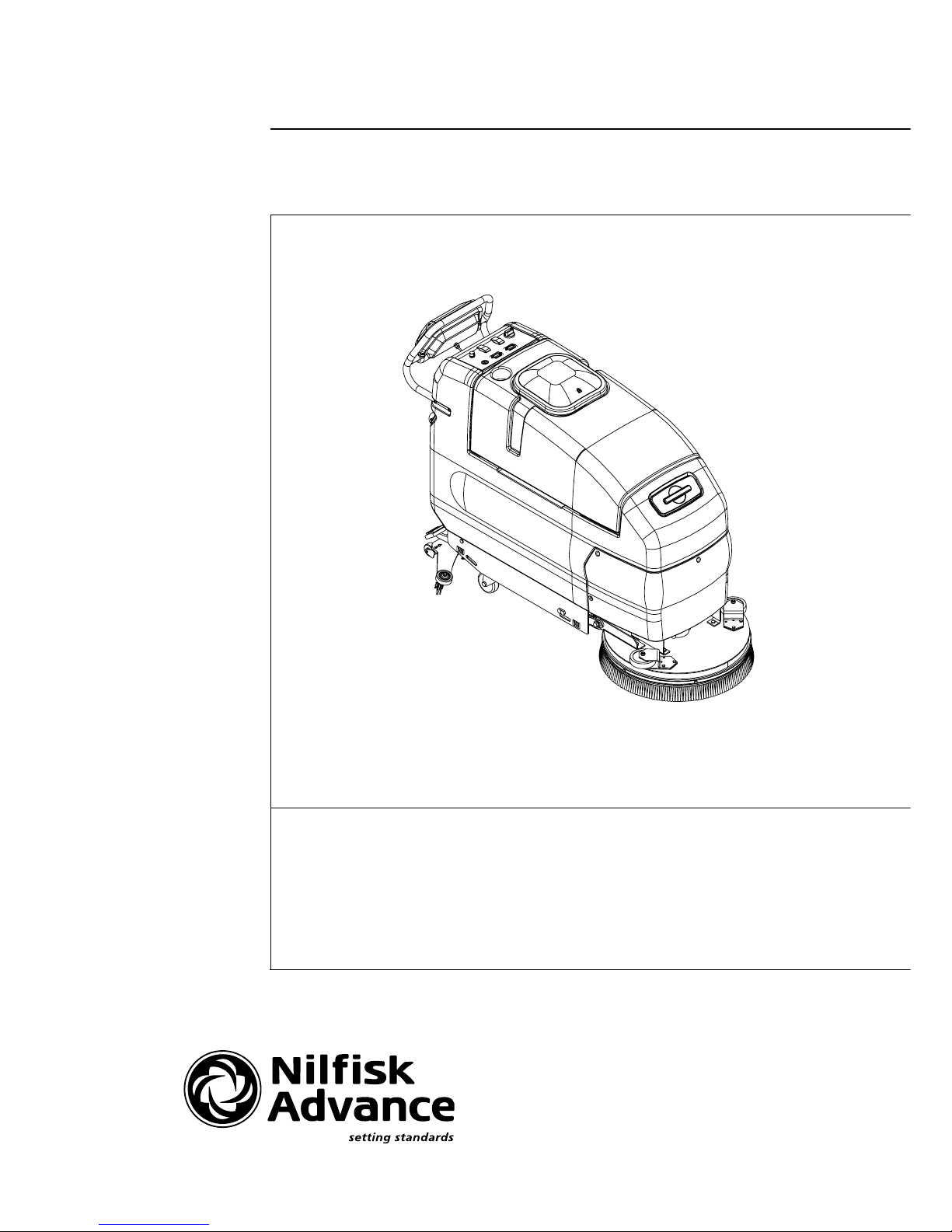
ConvertaMAX™ 20/26
BA 550/650
SERVICE MANUAL
Advance MODELS 56397010, 56397011
56397580, 56397581
Nilfisk MODELS 56397012, 56397013
56397582, 56397583

FORM NO. 56043056 / ConvertaMAX™ 20/26 / BA 550/650 - 1
GENERAL INFORMATION ..................................................................................................................................................2
SAFETY INSTRUCTIONS....................................................................................................................................................3
SPECIFICATIONS & MAINTENANCE ............................................................................................................................. 4-6
PM CHECKLIST .................................................................................................................................................................7
KNOW YOUR MACHINE ............................................................................................................................................... 9-13
SOLUTION SYSTEM ................................................................................................................................................... 14-19
FUNCTIONAL OVERVIEW ..............................................................................................................................................14
SOLUTION SYSTEM TROUBLESHOOTING ............................................................................................................ 15-17
SOLUTION SOLENOID VALVE AND STRAINER REMOVAL.........................................................................................18
SOLUTION SOLENOID VALVE DISASSEMBLY AND CLEANING.................................................................................19
SOLUTION FLOW CONTROL VALVE REMOVAL ..........................................................................................................19
SCRUB BRUSH SYSTEM............................................................................................................................................ 20-27
FUNCTIONAL OVERVIEW ..............................................................................................................................................20
TROUBLESHOOTING GUIDE ................................................................................................................................... 21-24
SCRUB BRUSH DECK REMOVAL 20/550 ......................................................................................................................25
SCRUB BRUSH MOTOR/GEARBOX REMOVAL 20/550................................................................................................25
SCRUB BRUSH DECK REMOVAL 26/650 ................................................................................................................ 26-27
SCRUB BRUSH MOTOR/GEARBOX REMOVAL 26/650................................................................................................26
SCRUB BRUSH HEAD SWITCH ADJUSTMENT (machines built before March 2001) ..................................................28
SCRUB BRUSH HEAD SWITCH ADJUSTMENT (machines built after February 2001) .................................................29
RECOVERY SYSTEM.................................................................................................................................................. 30-35
FUNCTIONAL OVERVIEW ..............................................................................................................................................30
VACUUM/RECOVERY SYSTEM MAINTENANCE CHECKLIST.....................................................................................31
TROUBLESHOOTING GUIDE ................................................................................................................................... 31-33
MAINTENANCE OF FLOAT CAGE AND FLOAT DUCT .................................................................................................34
VACUUM MOTOR REMOVAL .........................................................................................................................................35
RECOVERY TANK REMOVAL ........................................................................................................................................35
VACUUM SWITCH REPLACEMENT AND ADJUSTMENT .............................................................................................35
SQUEEGEE SYSTEM.................................................................................................................................................. 36-37
SQUEEGEE TOOL BLADE REPLACEMENT ..................................................................................................................36
SQUEEGEE TOOL ANGLE ADJUSTMENT ....................................................................................................................36
WHEEL DRIVE SYSTEM ............................................................................................................................................. 38-45
FUNCTIONAL OVERVIEW ..............................................................................................................................................38
TROUBLESHOOTING GUIDE ................................................................................................................................... 39-41
CHAIN MAINTENANCE ...................................................................................................................................................42
CHAIN REMOVAL AND ADJUSTMENT ..........................................................................................................................42
WHEEL DRIVE MOTOR REMOVAL ................................................................................................................................42
DRIVE WHEEL REMOVAL ..............................................................................................................................................42
POTENTIOMETER (5K) TESTING AND REMOVAL (for machines built before December 1, 2000)..............................44
POTENTIOMETER INSTALLATION AND ADJUSTMENT (machines before December 1, 2000)..................................45
POTENTIOMETER (5K) TESTING AND REMOVAL (for machines built after December 1, 2000).................................46
POTENTIOMETER INSTALLATION AND ADJUSTMENT (machines after December 1, 2000)............................... 46-47
POTENTIOMETER (25K) TESTING ................................................................................................................................47
ELECTRICAL SYSTEM................................................................................................................................................ 48-53
BATTERIES / CHARGERS SPECIFICATIONS ...............................................................................................................48
INSTALL THE BATTERIES ..............................................................................................................................................48
DESCRIPTION OF THE BATTERY LOW VOLTAGE CUTOUT FEATURE .................................................................... 49
CHARGING BATTERIES .................................................................................................................................................50
BATTERY MAINTENANCE AND BATTERY TESTING ...................................................................................................50
ELECTRICAL COMPONENT LOCATION........................................................................................................................51
WIRING SCHEMATIC ......................................................................................................................................................52
WIRING DIAGRAM .......................................................................................................................................................... 53
Note: All references to right, left, front, or rear in this manual are as seen from the operator’s stand-point.
TABLE OF CONTENTS
revised 7/02

2 - FORM NO. 56043056 / ConvertaMAX™ 20/26 / BA 550/650
INTRODUCTION
This manual will help you get the most from your ConvertaMAX™ 20/26 / BA 550/650. Read it thoroughly before servicing the machine.
Note: Bold numbers in parentheses indicate an item illustrated on pages 9-10.
This product is intended for commercial use only.
PARTS AND SERVICE
Repairs, when required, should be performed by your Authorized Nilfisk-Advance Service Center, who employs factory trained service personnel,
and maintains an inventory of Nilfisk-Advance original replacement parts and accessories.
Call the NILFISK-ADVANCE DEALER named below for repair parts or service. Please specify the Model and Serial Number when discussing
your machine.
(Dealer, affix service sticker here.)
NAME PLATE
The Model Number and Serial Number of your machine are shown on the Nameplate on the machine. This information is needed when ordering
repair parts for the machine. Use the space below to note the Model Number and Serial Number of your machine for future reference.
MODEL NUMBER
SERIAL NUMBER
TRANSPORTING THE MACHINE
CAUTION!
Before transporting the machine on an open truck or trailer, make sure that . . .
• The machine is tied down securely - see tie-down locations (26).
• All access doors and covers are secured (tape and strap as needed).
TOWING
CAUTION!
If the machine must be towed or pushed, make sure the Key Switch (Main Power) (18) is in the OFF position, disconnect wheel drive
motor wiring harness and do not move the machine faster than a normal walking pace (2-3 mph, 3-5kph) and for short distances only.
OTHER MANUALS AVAILABLE FOR YOUR MACHINE
The following manuals are available from the Nilfisk-Advance Literature Service Department (order according to model name, model number and machine’s serial
number):
• A Parts List and Operation Manual are available for each machine.
• The three Operation Manuals available for the BA 550/650 are multi-language: (Danish, Norwegian, Swedish, Finnish), (English, German, French,
Netherlands) or (Spanish, Portuguese, Italian, Greek)
GENERAL INFORMATION
revised 7/02

FORM NO. 56043056 / ConvertaMAX™ 20/26 / BA 550/650 - 3
SYMBOLS
Nilfisk-Advance uses the symbols below to signal potentially dangerous conditions. Always read this information carefully and take
the necessary steps to protect personnel and property.
DANGER!
Is used to warn of immediate hazards that will cause severe personal injury or death.
WARNING!
Is used to call attention to a situation that could cause severe personal injury.
CAUTION!
Is used to call attention to a situation that could cause minor personal injury or damage to the machine or other property.
GENERAL SAFETY INSTRUCTIONS
Specific Cautions and Warnings are included to warn you of potential exposure to machine damage or bodily harm.
WARNING!
• This machine should only be used by properly trained and authorized persons.
• Keep sparks, flame and smoking materials away from batteries. Explosive gases are vented during normal operation.
• Charging the batteries produces highly explosive hydrogen gas. Charge batteries only in well-ventilated areas, away from open
flame. Do not smoke while charging the batteries.
• Remove all jewelry when working near electrical components.
• Turn the key switch off (O) and disconnect the batteries before servicing electrical components.
• Never work under a machine without safety blocks or stands to support the machine.
• Do not dispense flammable cleaning agents, operate the machine on or near these agents, or operate in areas where flammable
liquids exist.
• Do not clean this machine with a pressure washer.
• Do not operate this machine on ramps or inclines of more than a 2 percent gradient.
CAUTION!
• This machine is not approved for use on public paths or roads.
• This machine is not suitable for picking up hazardous dust.
• Use care when using scarifier discs and grinding stones. Advance will not be held responsible for any damage to floor surfaces
caused by scarifiers or grinding stones.
• When operating this machine, ensure that third parties, particularly children, are not endangered.
• Before performing any service function, carefully read all instructions pertaining to that function.
• Do not leave the machine unattended without first turning the key switch off (O), removing the key and securing the machine.
• Turn the key switch off (O) before changing the brush(es), and before opening any access panels.
• Take precautions to prevent hair, jewelry, or loose clothing from becoming caught in moving parts.
• Use caution when moving this machine in below freezing temperature conditions. Any water in the solution or recovery tanks
or in the hose lines could freeze.
SAVE THESE INSTRUCTIONS
CAUTIONS AND WARNINGS

4 - FORM NO. 56043056 / ConvertaMAX™ 20/26 / BA 550/650
General Specifications English (Metric)
Machine Length
20” Models 64 in. (162cm)
26” Models 59 in. (149cm)
Machine Width with Squeegee
20” Models 30.5 in. (77cm)
26” Models 36.25 in. (92cm)
Machine Height 42.5 in. 108cm)
Machine Net Weight*
20” Models 362 lbs. (164kg)
26” Models 384 lbs. (174kg)
Machine Gross Weight**
20” Models 626 lbs. (284kg)
26” Models 648 lbs. (297kg)
Cleaning Width (scrubbing path)
20” Models 20 inches (51cm)
26” Models 26 inches (66cm)
Coverage Rate Per Hour (theory)
20” Models 28,000 sq. ft. (2600m2)
26” Models 34,500 sq. ft. (3205m2)
Coverage Rate Per Hour (average)
20” Models 9,000 sq. ft. (836 m2)
26” Models 11,300 sq. ft. (1050 m2)
Brush Diameter 20” Models (qty of 1) 20 inches (50.8cm)
Brush Diameter 26” Models (qty of 2) 13 inches (36cm)
Brush Speed (20”) 200 RPM
Brush Speed (2 x 13”) 220 RPM
Brush Pressure
20” Models Low - 45 lbs. (20kg) High – 80 lbs. (36kg)
26” Models Low – 70 lbs. (32kg) High – 110 lbs. (50kg)
Solution Tank Capacity 20 gal. (76l.)
Recovery Tank Capacity 20 gal. (76l.)
Vacuum Water Lift 63 inches (sealed)
14 inches (open hole adapter 1”)
Ramp Climbing Ability (gradeability) 2% grade
Sound power level as per ISO 3744 (at operator) 70 dB(A)/20µPa
Transport Speed (Maximum) 3.3 mph (5.3KPH)
Scrubbing Speed (Maximum) 3 mph (4.8KPH)
Power Source 24VDC Battery Pack (4) 6V/238 AH batteries
Battery Weight (each) 66lbs. (29.9kg)
Battery Compartment Size
Height 13.25 inches (33.6cm)
Width 15.5 inches (39.3cm)
Length 20.5 inches (52cm)
Battery Chargers Automatic 24V – 20A DC / 115V 60Hz AC
Wheel Drive Motor .5 hp, 373 watt
Brush Drive Motor (20” Models) (1) 1 hp, 746 watt
Brush Drive Motor (26” Models) (2) .75 hp, 560 watt
Vacuum Motor .75 hp, 570 watt
Machine Current (Average) 20” Models: 40 Amps 26” Models: 50 Amps
*Net Weight: Standard machine without options, empty solution and recovery tanks, without removable scrub brushes and no battery installed.
**Gross Weight: Standard machine without options, empty solution tank and empty recovery tank, with removable scrub brushes and 238 AH batteries.
SPECIFICATIONS
revised 9/00
FORM NO. 56043056 / ConvertaMAX™ 20/26 / BA 550/650 - 5
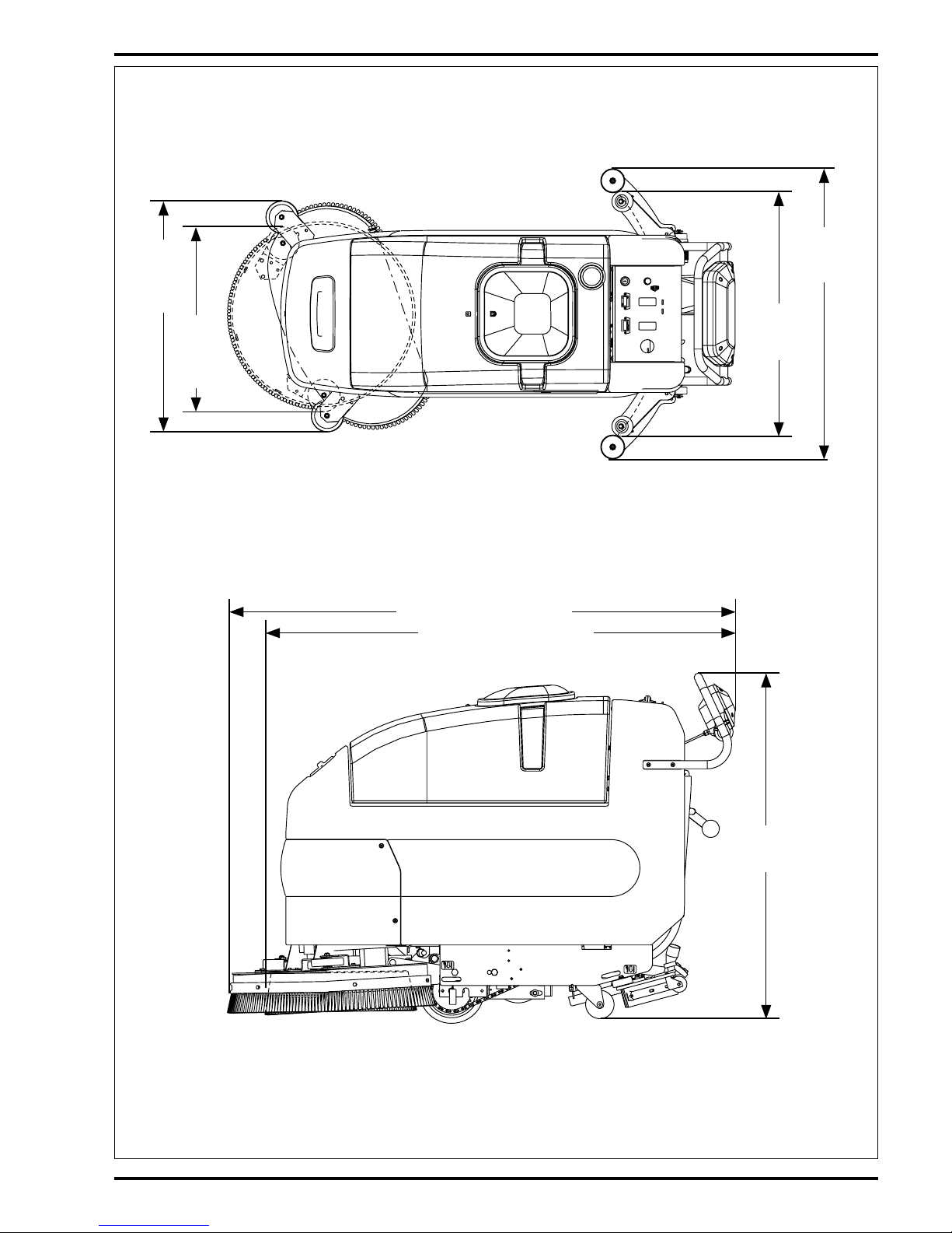
SPECIFICATIONS
TOP VIEW
SIDE VIEW
30.5 in.
(77cm)
20" Models
64 in. (162cm) 20" Models
59 in. (149cm) 26" Models
42.5 in.
(108cm)
26.5 in.
(67.3cm)
20"
Models
28.5 in.
(72.4cm)
26"
Models
36.25 in.
(92cm)
26" Models

6 - FORM NO. 56043056 / ConvertaMAX™ 20/26 / BA 550/650
MAINTENANCE
MAINTENANCE SCHEDULE
Maintenance intervals given are for average operating conditions. Machines used in severe operational environments may require
service more often.
MAINTENANCE ITEM Daily Weekly Monthly Yearly
Charge Batteries •
Drain/Clean and Check Tanks & Hoses •
Check/Clean/Rotate the Brushes/Pads •
Check/Clean/Adjust the Squeegee ••
Check/Clean Vacuum Shut-Off Float •
Check Each Battery Cell(s) Water Level •
Inspect and Clean Solution Filter •
Lubrication – Grease Fittings •
*Check Motor Carbon Brushes •
Note: See the individual machine system sections for maintenance information.
* Have Nilfisk-Advance:
IMPORTANT!
Motor damage resulting from failure to service the carbon brushes is not covered under warranty. See the Limited Warranty
Statement.
Check vacuum motor carbon brushes (Qty 2) once a year or after 300 operating hours.
Note if the vacuum or brush motor carbon brushes are 9.5mm (3/8 inches) or shorter, replace them.
Check brush motor carbon brushes (Qty 4) once a year or after 500 operating hours.
Check wheel drive motor carbon brushes every 500 operating hours. The original length of each brush is 20mm (25/32 inches).
Replace when shorter than 9.5 mm (3/8 inches) to obtain the same motor efficiency as a new brush.
WARNING!
Turn the key switch off and disconnect the battery before servicing the machine.
BATTERIES AND CHARGERS
Attention: See the electrical system manual section for battery installation and charger system requirements.
LUBRICATING THE MACHINE
Once a month, pump a small amount of grease into each grease fitting on the machine until grease seeps out around the bearings.
Grease fitting locations are:
• Rear Caster Wheel Axle & Swivel (2) per Assembly
Once a month, apply light machine oil to lubricate the:
•Drive Chain
• Squeegee Height Adjustment Caster Hardware
•Pivot Points For the Squeegee & Scrub Brush Linkage
FORM NO. 56043056 / ConvertaMAX™ 20/26 / BA 550/650 - 7
revised 7/02
Copyright 2001 Nilfisk-Advance. 8/09/01
Advance ConvertaMAX 20/26 Models 56397010, 56397011, 56397580, 56397581
Nilfisk BA 550/650 Models 56397012, 56397013, 56397582, 56397583
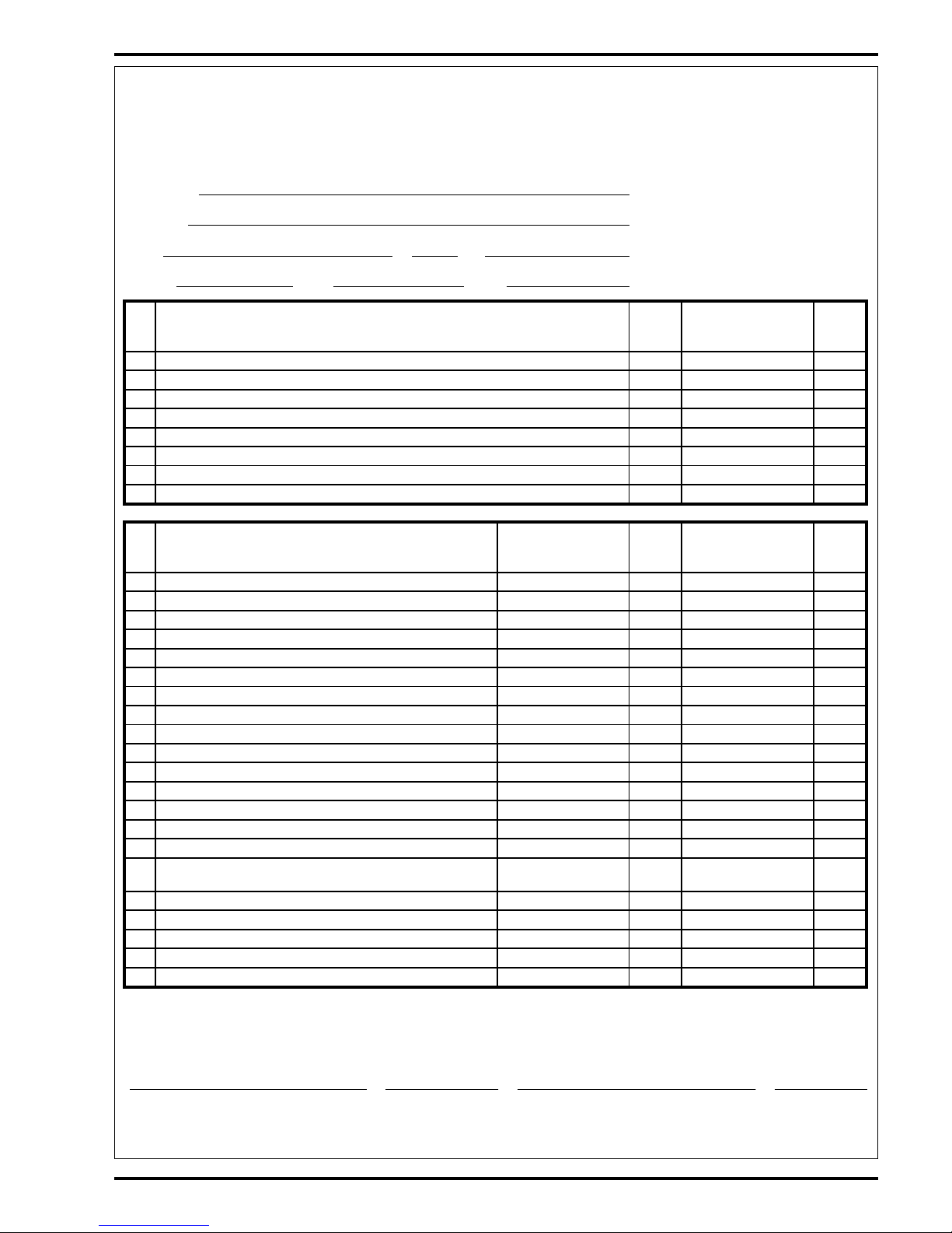
PM Checklist
Defect Codes
Customer
A needs adjustment
B binding
Address
C dirty or contaminated
D damaged, bent or torn
City
St Zip L leaks
M missing
Model
Serial Hours W worn out
Ref
OPERATIONAL INSPECTION ITEMS
OK
Defect Codes
(circle)
Does
Not
Work
1Drive Paddle Operation (check for Fwd/Rev Drive & any neutral creep) A B D
2Drive System Performance (Speed Changes Min/Max) noisy sluggish
3 Scrub System (Raise/Lower, Brush Motor On/Off, Brush install & Remove Feature) A B D
4 Scrub Brush (pressure settings Normal & Heavy) A B
5 Squeegee System (Raise/Lower & Squeegee Tool pickup Performance) A B D
6Vacuum Performance (Sealed water lift 63" and 1- inch open hole adapter 14 inches) C L W
7 Solution Control (On/Off Manual /Auto and Flow Volume Min/Max) A B L
8Battery Charger (Auto turn ON & OFF) D
Ref
VISUAL INSPECTION ITEMS
Comments OK
Defect Codes
(circle)
Does
Not
Work
9 Scrub Brushes, check for wear and rotate D M W
10 Scrub Brush Motor(s), check for carbon brush wear 500 Hours B C W
11 Scrub Brush Motor(s), check gearboxes B D L
12 Brush Drive Plate Retainer Clips & flex couplers C D M
13 Scrub Deck Skirts and Side Wheels D M W
14 Solution Solenoid Valve C D L W
15 Solution Flow Control Valve and Linkage A B D W
16 Solution Tank, Delivery Hoses & Filter Clean filter screen C L
17 Vacuum Motor Carbon Brushes (wear limit 3/8”) 300 Hours B C W
18 Vacuum Motor Gaskets and Filters C D L
19 Vacuum Float Ball & Cage Assembly Clean float C D M
20 Recovery Tank Cover Gasket L M W
21 Recovery Tank Drain Hose & Cap C D L
22 Squeegee Pick-Up Hose Back flush C D L
23 Squeegee Tool & Blades (clean & rotate) A D W
24 Squeegee Tool Wheels (lubricate) Two side and two
floor
A D W
25 Battery Condition (load test, clean & water) C W
26 Front Drive Wheel Motor Check Carbon Brushes 500 Hours B C W
27 Front Drive Tire tread wear W
28 Drive wheel Motor Chain (Lubricate and tension) A B C W
29 Rear chassis Caster Wheels (Lubricate) tread wear W
NOTE: For additional service information see service manual form number 56043056 and
operators manual form numbers 56041459, 56041460, 56041461.
WORK COMPLETED BY: ACKNOWLEDGED BY:
Service Technician Signature Date Customer Signature Date

8 - FORM NO. 56043056 / ConvertaMAX™ 20/26 / BA 550/650
BLANK PAGE
revised 9/01
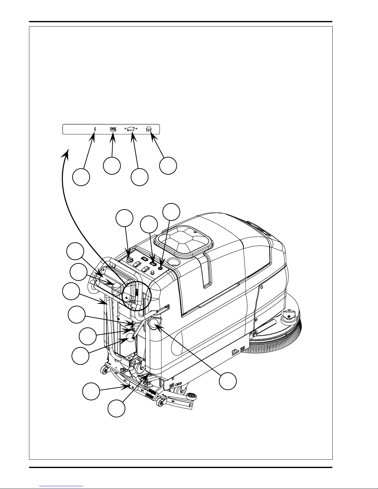
FORM NO. 56043056 / ConvertaMAX™ 20/26 / BA 550/650 - 9
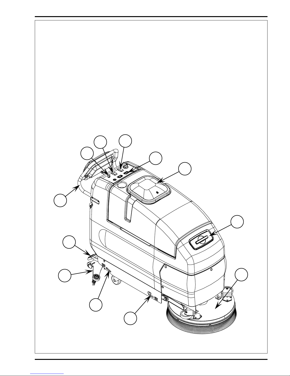
1 Solution Tank Fill Openings (2)
2 Recovery Tank Cover
3 Vacuum / Squeegee Lever
4 Brush Raise / Lower Pedal
5 Drive Paddle
6 Solution Drain Hose / Level Indicator
7 Recovery Drain Hose
8 Squeegee Adjustment Knob
9 Squeegee Blade Latch
10 Squeegee
11 Battery Charger Connector
12 Battery Fuel Gauge
13 Hour Meter
14 Solution Switch, ON-Momentarily ON-OFF
15 Brush Remove Switch
16 Solution Flow Control Knob
17 Speed Limit Control Knob
18 Master Key Switch
19 Auxiliary Circuit Breaker
20 Vacuum Motor Circuit Breaker
21 Brush Motor Circuit Breaker
22 Wheel Drive Circuit Breaker
23 Scrub Pressure Lever
24 Brush Deck
25 Operator Control Handle
26 Tie Downs
1
2
10
4
12
14
15
17
24
25
26
26
KNOW YOUR MACHINE
revised 9/01
10 - FORM NO. 56043056 / ConvertaMAX™ 20/26 / BA 550/650
3
5
6
8
9
11
13
16
18
19
20
22
21
23
7
1
KNOW YOUR MACHINE
revised 9/01

FORM NO. 56043056 / ConvertaMAX™ 20/26 / BA 550/650 - 11
FUNCTIONAL DESCRIPTION OF CONTROL BUTTONS:
Solution Tank Fill (1) – Open to fill the solution tank, use non-foaming chemicals only (capacity 20 gal. / 75 liters)
Recovery Tank Cover (2) – Point of entry for waste water into tank. Also houses float ball which shuts off vacuum port to vac motor
when tank is full.
Squeegee Lever (3) – This lever controls both the squeegee and the vacuum motor. There are three positions: OFF, vacuum ON
and vacuum ON with the squeegee on the floor.
*Off
* Vacuum ON
This position lifts the squeegee slightly while leaving the vacuum turned on. This can be used for backing up during scrubbing,
or supplies vacuum for cleaning remote areas using an attachment.
* Vacuum ON with the squeegee on the floor
This position is for picking up solution while scrubbing.
Brush Raise / Lower Pedal (4) – Located at the right rear corner near the floor, this pedal is used to raise or lower the brush head.
Drive Paddle (5) – Located on top at the rear of the machine, the operator can make the machine go forward by pushing forward
on it, or reverse by pulling backward on it. The speed is variable depending on how far forward or backward the paddle is moved.
When the brush head is in the “DOWN” position, the brushes and solution will operate when the drive is engaged in either direction,
but will stop after the machine is stationary for 1 second.
Solution Drain Hose / Level Indicator (6) – Used to empty the solution tank and show current level of solution in tank, graduations
are marked on the side of the solution tank next to the hose.
Recovery Drain Hose (7) – Used to empty the recovery tank.
Squeegee Adjustment Knob (8) – Used to adjust the tilt of the squeegee. Turn knob clockwise to tilt the squeegee backwards and
counter-clockwise to tilt it forward.
Squeegee Blade Latch (9) – Holds rear squeegee blade and straps in place, release to replace rear blade.
Squeegee (10) – Picks up solution after scrubbing.
Battery Charger Connector (11) – Plug battery charger into this port to charge batteries.
Battery Fuel Gauge (12) – Shows current state of charge of batteries.
Hour Meter (13) – Displays number of hours machine has been used.
Solution Switch (14) – This switch is used to select the mode of operation for the solution system. There are 3 modes of operation
for this system. The modes are OFF, ON, MOMENTARY ON. Following is a description of each mode and how they are selected.
OFF: In this mode the solution flow is turned off.
ON: In this mode the solution flow will be turned on whenever the Drive Paddle (5) is in forward or reverse mode and the brush head
is down. The solution flow will be turned off otherwise.
MOMENTARY ON: – Solution can be dispensed by pressing and holding the solution button. Solution will be dispensed for as long
as the button is held. This is for pre-wetting the floor prior to scrubbing.
KNOW YOUR MACHINE
revised 9/01

12 - FORM NO. 56043056 / ConvertaMAX™ 20/26 / BA 550/650
Brush Remove Switch (15) – To remove the brush(es) from the machine, have the machine stationary and the Brush Deck (24) in
the “RAISED” position. Press the switch to the “REMOVE” position and release. The switch will snap to the OFF position, and the
brush(es) will drop to the floor.
Solution Flow Control Knob (16) – Turn this dial to the right to increase solution flow to the floor. Turn to the left, to decrease the
amount of solution flow to the floor. When the Drive Paddle (5) is released from either forward or reverse travel, the solution flow will
stop automatically, and resume when the drive is engaged.
Speed Limit Control Knob (17) – The Speed Limit Control Knob is used to adjust the maximum speed in both forward and reverse.
Master Key Switch (18) – The master power switch.
Auxiliary Circuit Breaker (19) – Provides overload protection. If it trips, it will pop out. To reset, wait one minute and press the button
back in. If any breaker trips repeatedly, have the machine serviced.
Vacuum Motor Circuit Breaker (20) – Provides overload protection to machine’s vacuum motor. If it trips, it will pop out. To reset,
wait one minute and press the button back in. If any breaker trips repeatedly, have the machine serviced.
Brush Motor Circuit Breaker (21) – Provides overload protection to machine’s brush motor(s). If it trips, it will pop out. To reset,
wait one minute and press the button back in. If any breaker trips repeatedly, have the machine serviced.
Wheel Drive Circuit Breaker (22) – Provides overload protection to machine’s wheel drive motor. If it trips, it will pop out. To reset,
wait one minute and press the button back in. If any breaker trips repeatedly, have the machine serviced.
Scrub Pressure Lever (23) – Two position lever provides two different scrubbing pressures.
TOP POSITION: – In this position the full weight of the scrub deck rests on the floor.
BOTTOM POSITION: – In this position the scrub pressure is approximately 30 pounds less.
Brush Deck (24) – Contains brush drive motor(s) and brush(es).
Operator Control Handle (25) – Operator holds onto this to control the machine.
KNOW YOUR MACHINE
revised 9/01

FORM NO. 56043056 / ConvertaMAX™ 20/26 / BA 550/650 - 13
CONTROL MODULE DESCRIPTION
The ConvertaMAX™ 20/26 / BA 550/650 scrubbers have an electronic module that controls the activation of the scrub brush motors
for scrubbing and removal of the brushes/pads and the low voltage cutout function.
For normal scrubbing the brush motor(s) will activate only if the brushes are down and the Drive Paddle (5) (throttle) is in the forward
or reverse position.
For removal of the brushes/pads the scrub deck must be in the up position. To remove the brushes/pads simply depress the Brush
Remove Switch (15). The module will momentarily run the brush motor and then stop it quickly.
The low voltage cutout is adjustable for two different thresholds. The normal setting cuts out at 1.75 volts per cell and the alternate
setting cuts out at 1.83 volts per cell. The cutout level is selected by momentarily depressing the pushbutton switch located on the
module circuit board.
*Important Note: See the Low Voltage Cutout Level Selection manual section in the Electrical System and follow the instructions
for setting the low voltage cutout threshold.
DESCRIPTION OF THE BATTERY FUEL GAUGE
The Battery Fuel Gauge (12) uses a 10 bar LED display that indicates the state of the batteries charge, successively, bar by bar, from
full to empty. At 70% depth of discharge a single flashing light signals an energy reserve alert. At 80% of discharge, a double flashing
light signals an empty alarm. The battery gauge will retain the last state-of-charge condition even when the machine has been turned
off. The battery fuel gauge state-of-charge display indication is automatically reset to full charge when the battery pack is recharged.
KNOW YOUR MACHINE
revised 9/01
14 - FORM NO. 56043056 ConvertaMAX™ 20/26 / BA 550/650
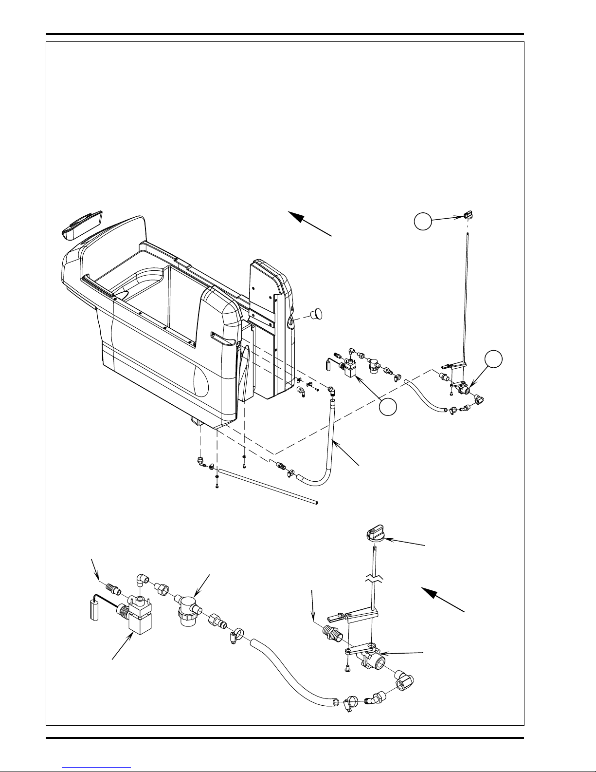
SOLUTION SYSTEM
FRONT
Solution
Solenoid Valve
(L1)
Solution Filter
Main Solution
Valve
To Brush(es)
Solution Flow
Control Knob
From Solution
Tank
FRONT
A
B
C
Drain Hose
FUNCTIONAL OVERVIEW
The 20-gallon (76 l.) capacity solution tank uses two fill openings one located in the front and another in the rear, which offers ease of filling. Plumbed
onto the tank outlet is a serviceable solution filter, to keep debris from entering the solenoid valve. Also fitted to the tank is flexible hose used to
indicate the solution level and to drain the tank for system maintenance.
See Figure 1. The solution system uses (2) valves to regulate the amount of solution dispensed onto the floor. The Knob (A) located on the control
panel operates the Main Solution Valve (B) that controls the needed flow volume demanded by the scrub brushes. The electrical solenoid valve
(L1) (C) and control panel mounted solution switch (S2) start and stop the solution flow (See Electrical Diagram).
During normal machine operation the (S2) solution switch when turned ON works in conjunction with the wheel drive controller components and
brush motor solenoid output to energize the (L1) solenoid valve. The solution will flow to the scrub brushes when the main flow control valve is
open, the scrub deck is lowered and the handle drive paddle (box) is pushed or pulled into Fwd or Rev. Note: When the solution On/Off switch
(S2) is turned Off, no flow can occur regardless of the main valve being On and the drive control paddle being activated.
FIGURE 1
FIGURE 2
revised 9/01
FORM NO. 56043056 ConvertaMAX™ 20/26 / BA 550/650 - 15
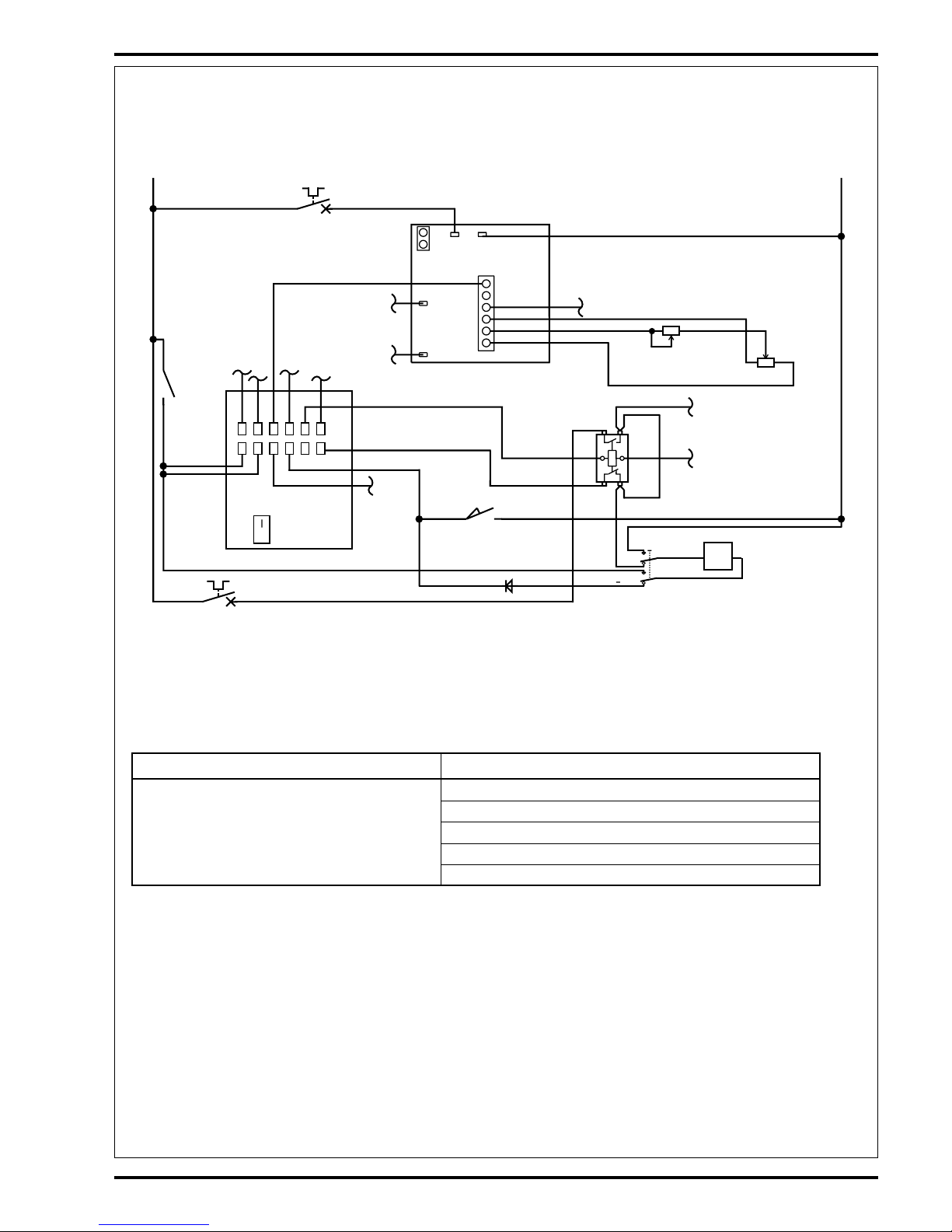
SOLUTION SYSTEM
-
+
1
2
3
4
5
6
5124
3
10
61
11
987
2
S6
D2
L1
R1
R2
S2
K1
F2
A2
Voltage Cutout
Button
LIQ
.
GEL
.
A1
F3
P1
B-B+
P2
+24V -24V
S1
YEL/BLK
YEL/WHT
VIO/BLK
BLK/YEL
VIO
BLK
ORN/BLK
WHT/RED
#12
VIO/BLK
#10
BLK
VIO
Electrical Diagram (Solution Switch Closed in the Full ON Position)
*For complete description of all callouts see Electrical System Wiring Diagram.
TROUBLESHOOTING GUIDE
Problem Possible Cause
Inadequate or no solution flow No solution in the tank
Main solution flow control valve knob is in the off position
Clogged solution filter, valves and hoses
Defective solution solenoid valve (L1)*
Defective control panel solution switch (S2)**
*See Solenoid Troubleshooting flow chart Symptom One for electrical system diagnostics.
**See Troubleshooting flow chart Symptom Two.
FIGURE 3
revised 9/01
16 - FORM NO. 56043056 ConvertaMAX™ 20/26 / BA 550/650
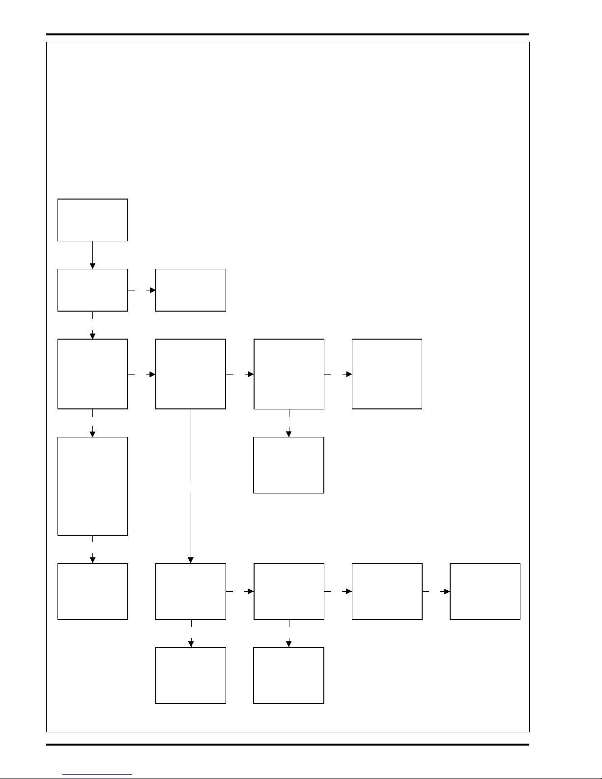
SOLUTION SYSTEM
No
Yes
Yes
No
Yes
No No
Yes
Yes
No No
Yes
No
Yes
Solenoid will
not open, no
solution flow
(See Figure 3).
Verify scrub
brush(es) are
turning
See Brush System
Troubleshooting
Symptom 2 (part
A&B).
Separate the wiring
harness connector
that feeds the L1
solenoid (2 wires
Yel/Wht & Yel/Blk).
Test for 24V
Test the resis-
tance of the L1
solenoid coil. If it
reads infinity coil
is open or if it
reads 40 ohms or
less it is shorted
(a good coil
should read 63
ohms ±10%).
Check for 24V
(Pos.) from the
Yel/Wht L1 harness
feed wire to a
(Neg.) battery
standoff
Replace the L1
solenoid coil if
testing shows it
shorted or open.
Check for 24V
(Pos.) at the
Blk/Yel input wire
on the S2 solution
switch
Test continuity of
the Blk/Yel & #12
wires from the K1
solenoid to the S2
solution switch.
Repair or replace
Replace the S2
solution switch
Check for 24V
(Neg.) from the
Yel/Blk L1 harness
feed wire to a (Pos.)
battery standoff
Check for 24V
(Neg.) at the
Vio/Blk input wire
on the S2 solution
switch
Replace the S2
solution switch
Check diode D2
for continuity in
one direction only
If diode checks
open replace the
D2 diode
Replace the L1
solenoid valve
TROUBLESHOOTING GUIDE ELECTRICAL
Possible Symptoms
1 Solution solenoid valve will not open when the solution switch is in the full on position.
2 Solution solenoid valve will not open when the solution switch is in the momentary on position.
SYMPTOM ONE
Note: Do all testing with the key switch on, brush switch closed (scrub deck lowered) and the drive paddle activated
(pushed Fwd or pulled into Rev).
revised 9/01
 Loading...