

Page 1
Page 2

English
2
Page 3

Components Symbols used to mark instructions.............................................4
Attachments Included Attachments.................................................................5
Accessories Included Accessories..................................................................6
Guidance Congratulations...........................................................................7
Getting the best results...............................................................7
Installation Assembly.....................................................................................8
Warnings.....................................................................................8
Operation Switching on the machine...........................................................9
Using the machine......................................................................10
During Use..................................................................................10
Maintenance Daily............................................................................................11
Weekly........................................................................................11
Precautions Do’s & Don’ts..............................................................................12
Service Guarantee...................................................................................12
Technical Technical Data............................................................................13
Troubleshooting Symptom, possible cause & action.............................................14
Contents
English
Modified January 2010
3
Page 4
English
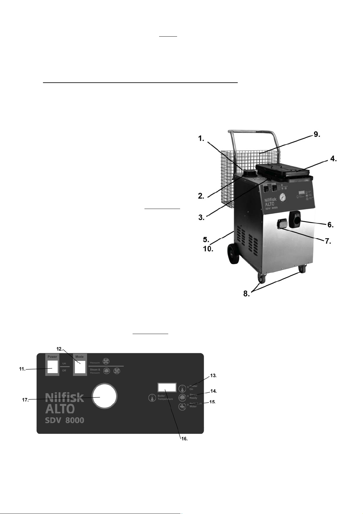
Components
1. Detergent Connection Point
2. Cold Water Tank
3. Steam Control
4. Collection Tank
5. Filter Panel
6. Vacuum Hose Socket
7. Steam Hose Socket
8. Castor With Brake
9. Wire Basket
10. Serial Number
Diagram A
Diagram B
11. On/Off Switch
12. Mode Switch
13. Heater On LED
14. Steam Ready LED
15. Cold Water Refill LED
16. Temperature Display LED
17. Pressure Gauge
4
Page 5
English
p
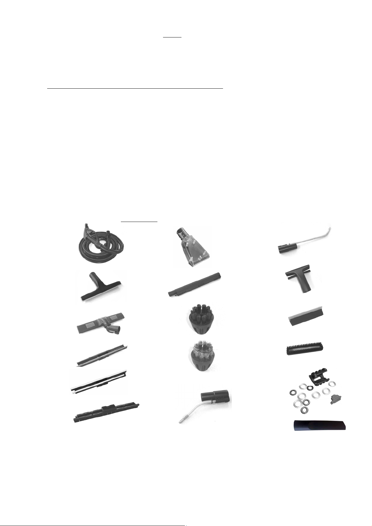
Attachments
These Parts were carefully packed at Nilfisk ALTO. Please check all accessories on receipt. If any parts are
missing or damaged please contact the company in which you purchased this machine, within 7 days of
1. 7. 12.
13.
2. 8.
14.
9.
3.
15..
10.
4.
16.
11.
17.
urchase quoting your serial number on the back of the machine.
1. 4 Meter Steam, Detergent & Vacuum Hose 2. Glass Washer
3. Floor Nozzle 400mm 4. Squeegee Insert for Floor Nozzle
5. Carpet Insert for Floor Nozzle 6. Brush Insert for Floor Nozzle
7. Clear Upholstery Tool 8. Extension Tubes x 2
9. Nylon Details Brush x 5 10. Brass Details Brush x 5
11. Short Steam Lance 12. Long Steam Lance
13. Suction Nozzle 150mm 14. Clip on Squeegee 150mm
15. Clip On Brush 150mm 16. Accessory Service Kit
17. Crevice Tool
Diagram C
5.
6.
Also available is Stainless Steel detail brushes (Packs of 10)
5
Page 6

English
,
•
Accessories
These Parts were carefully packed at Nilfisk ALTO. You will find these items in your box with all the attachments. Please check
all accessories on receipt. If any parts are missing or damaged please contact the company in which you purchased this
machine
within 7 days of purchase quoting your serial number on the back of the machine.
Diagram D
• Wire Basket
• Plastic Wing Nuts x 4
• Back Wheel Assembly
6
• Tubular Handle
• Detergent Bottle
Castor with Brake x2
Page 7

•
English
Guidance
Congratulations
………………………………………………...
We would like to take this oppo rtunity to thank you for your purchase of the Nilfisk ALTO combined
steam, detergent and vacuum cleaner.
This instruction manual contains all of the necessary information to operate and maintain this
machine. Please read this instruction manual carefully before you start using or carrying out any
maintenance on the machine.
If you use this machine correctly as stated in this instruction manual this machine will fulfil all your
steam cleaning needs.
The SDV8000 is manufactured in the EU to the highest quality Standards
• This machine is intended for use in a commercial cleaning environment. If you do not follow
the instructions contained in this manual, situations may arise which may be dangerous or
harmful to the machine or the person operating the machine. Read this manual carefully so
that you know when such situations can arise.
• Ensure that all operators of this machine are fully trained on how it works.
• Report any problems or damage to the machine immediately to the supplier or a Nilfisk
ALTO approved supplier for this product. Do not operate the machine until the problem or
damage has been resolved.
Getting the Best Results
………………………………………………...
• Operate the machine in accordance with
the instruction manual
• Maintain the machine in accordance with
instruction manual
Keep this manual in a safe place for future reference and ordering of spare parts
Use only parts supplied by Nilfisk ALTO approved
distributors
• Use only detergents and cleaning products in the solution
tank which have been approved by Nilfisk ALTO
7
Page 8

English
•
Installation
This machine has been designed with your safety in mind; however it is important that
you observe the following points for safe operation during the operating procedure
Lift the machine out of the box.
• Carefully place the machine on its side in order
to assemble the wheels securely.
!! A flat surface is required which will not
scratch or damage the surfaces of the machine.
• Diagram D – Back wheel assembly. Using a 10 mm spanner remove the bolts from the
machine and place the assembly into place towards the back of the machine. Tighten the
bolts securely ensuring no movement on the brackets.
• Diagram D – Casters with Brake x 2. Remove bolts from the machine and position into place
towards front of the machine. Tighten securely ensuring no movement on the brackets.
• Once all the wheels are fully assembled, resume the machine to its upright position.
• Place Tubular Handle (Diagram D) in position on the back of the machine and secure using
the 4 x Plastic Wing Nuts (Diagram D).
!! Do not screw them all the way in at this point.
• Place Wire Basket (Diagram D) over the Wing Nuts and tighten up to secure.
• Check all accessories are present in the box as shown in Diagram C & D.
Warnings
………………………………………………...
• This is an electrical product – Do not use in wet weather or allo w the machine to get wet.
• Do not discharge steam towards people, danger of scolding. Or towards equipment containing
electrical components
• Never allow children to play with this appliance.
• Do not use the machine for other purposes that it was built for.
• Please remember that the steam cleaner operates at temperatures in excess of 170°C. Never use it
on objects, which cannot resist the temperature (delicate materials, fabrics, plastics, wood etc).
Where any doubt exists check carefully on a part of the material where minor marks will not matter.
• Do not operate the machine or carry out any maintenance out on it
Unless you are trained and authorised to do so
Unless you have read and thoroughly understand this instruction manual.
8
Page 9

English
Operating Procedure
………………………………………………...
1. Switch mode switch (Number 12 Diagram B) to position 11.
• This will switch on the boiler elements and will enable you to use the handle controls on the
hose once connected.
2. Fill the cold water tank (Number 2 Diagram A) with clean cold
!! Anything other than clean cold water used in the
water tank will void the manufacturer’s warranty.
3. Connect the Detergent Bottle (Diagram B) to the detergent connection point (Number 1
Diagram A) on the machine.
4. Fill the detergent bottle (Diagram B) with Nilfisk ALTO approved detergent.
!! Unapproved detergent may be harmful or dangerous to the machine or the operator
using the machine. This may cause irrepairable damage to seals and will void the
manufacturers warranty.
5. Connect the Vacuum Hose to the front of the machine (Number 6 Diagram A) ensuring it locks
into position. To release the vacuum hose from the socket slide the red button upwards at the
same time as pulling the hose out.
!! If the Hose becomes damaged the complete hose must be replaced. Do not
attempt this task yourself, contact a Nilfisk ALTO approved supplier for replacement.
6. Connect the Steam Hose to the front of the machine (Number 7 Diagram A) ensuring it is
pushed in all the way and the pin on the flap locks into the hole on the hose.
!! Grease “O” rings on steam pin before connecting.
!! To release the steam hose, lift the flap and pull.
7. Plug the power cable into a 240 Volt supply.
!! Inspect the electric cable before every use. If the cable becomes damaged at
anytime the complete cable must be replaced by a Nilfisk ALTO approved distributor.
!! Never touch the power cable or plug with wet hands
!! Always unplug the machine when
i. The machine is not in use
ii. Cleaning the machine
iii. Any maintenance work is being carried out
8. Switch the On/Off switch (Number 11 Diagram B) to the ON position. The Heater On light LED
(Number 13 Diagram B) will illuminate.
9. Allow approximately 10 minutes for the boiler to heat the water
10. When the Steam Ready LED (Number 14 Diagram B) illuminates the machine is ready to be
used.
water only.
9
Page 10

English
Operating Procedure cont….
………………………………………………...
11. The handle controls are now active.
• The red trigger on the hose handle will release steam when pressed.
12. The steam output can be adjusted by the steam control knob (Number 3 Diagram A)
13. Choose and fit the required accessory (Diagram C) to the hose handle. Lock the accessory in
place by turning the accessory locking clip.
!! When changing accessories during use please note these will be hot.
During Use
………………………………………………...
Cold Water Tank Empty(Number 2 Diagram A)
1. Refill the cold water tank when the refill cold water LED (Number 15 Diagram B) is illuminated.
A buzzer will sound and the steam will no longer come out of the nozzle when the steam switch
on the handle is pressed.
2. Always empty the collection tank each time the cold-water tank is refilled.
3. The pumps will not work when the cold-water tank is empty.
4. Once the cold water refill LED is illuminated the boiler heater will remain on for 30 minutes. If the
cold-water tank is not refilled within 30 minutes and the machine is left powered on the boiler
heater will switch off.
Detergent Bottle Empty (Diagram D)
1. If the detergent does not come out of the nozzle when the detergent switch on the handle is
pressed, refill the detergent bottle (Diagram D)
Collection Tank Full (Number 4 Diagram A)
1. Always empty the collection tank each ti m e the col d -water tank is refilled
2. The pitch of the motor noise changes and there is no suction at the nozzle
3. Switch off the machine, empty the collection tank and rinse clean
• The red button on the side of the handle will lock the steam trigger in the off position.
• Pressing the left hand switch on top of the handle will activate the vacuum.
• Pressing the right hand momentary switch located on the top of the handle will
activate the detergent pump. Hold the switch as long as you need to dispense the
detergent. Releasing the switch will stop the detergent supply.
10
Page 11

y
Maintenance
DO
Warning: Disconnect the machine from the mains before
cleaning or carrying out any maintenance work.
Daily Maintenance
………………………………………………...
To be carried out every day or every 8 hours of operation.
1. Grease “O” rings on the steam pin in the steam hose.
2. Wash the hose by sucking one or two litres of water from a basin into the collection tank.
3. Empty the collection tank, rinse and wipe down.
4. Remove the foam filter, wash in water and re fit.
• Take care not to damage the filter mesh. If it becomes torn do not use the
machine and replace damaged parts immediately.
5. Rinse detergent bottle with clean water.
6. Wipe down the body of the machine with a clean damp cloth
7. Always wash the accessories in hot soapy water
DO NOT IMMERSE THE MACHINE OR HOSE IN WATER
8. Wrap the power cable around the handle before storage.
Weekly Maintenance
………………………………………………...
To be carried out every week or every 50 hours of operation.
As for daily maintenance plus the following:
1. Inspect the power cable for any signs of damage. If damaged do not repair, contact the
supplier of this product. Do not use until repaired.
2. Inspect the hose assembly for any signs of damage. If damaged do not repair, contact
the supplier of this product. Do not use until repaired.
3. Inspect castors to ensure all securing bolts are fully tightened.
Safety Precautions
………………………………………………...
This machine is to be used by trained operatives onl
• Check the cable and plug are safe and intact
before plugging the machine in.
• Place cleaning in progress signs where necessary
• Point the steam nozzle away from your body
during use
• Empty and clean machine after each use
English
DON’T
• Use the machine near people, children or
animals
• Point steam at electrical apparatus
• Use the machine to clean the machine down
• Do not use on Velvet, satin or leather
• Leave the machine unattended
11
Page 12

English
Service & Guarantee
If you require a service or advice on using or maintaining your
machine please contact your Nilfisk ALTO approved distributor.
Service
Guarantee
………………………………………………...
………………………………………………...
Nilfisk ALTO guarantees that if within 12 months from the date of purchase this appliance, or any
parts thereof, is proved to be defective by reason of faulty workmanship or materials, we will at our
option repair or replace the same free of charge for labour and materials, provided that:
• The appliance has been installed and used in accordance with our operating and servicing
instructions.
• If the appliance has been serviced, maintained, repaired, modified taken apart or
tampered with by any person not authorised by us, then we will not be liable under this
guarantee for any fault arising from their defective workmanship.
• We shall not be liable under this guarantee for any fault in the appliance arising from the
use of spare parts not supplied and recommended by us.
• Excluded from this guarantee are parts that need replacement due to normal wear and
tear such as hoses, nozzles and accessories.
12
Page 13

English
Technical
Technical Information
………………………………………………...
Boiler
Wattage: 3000W – (2000+1000)
Type: Stainless Steel
Capacity: 3.3 Litres
Continuous Fill Yes
Steam Pressure 8 Bar
Steam at source: 165°C >
Vacuum
Type Integral
Motor 850 Watt
Electrical
Voltage 230V ~ single phase
Low Voltage Controls 5V
Cord length 10m
Capacities
Boiler 3.3 Litres
Cold Water Tank 5 Litres (easy fill)
Collection Tank 12 Litres
Detergent Tank 2.5 Litres (easy fill)
Weight 35kg
13
Page 14

English
Trouble Shooting
Symptom Possible cause Action
No power Not connected / Faulty socket Check connection to wall socket and
socket switch. Try in another wall socket
On / Off switch not on Press On / Off switch which will illuminate
when on
Fuse blown Replace fuse with approved 13A fuse
Unknown Call for service
No steam Steam Control turned down fully
clockwise
Steamer not ready Wait for the “Ready to steam” light to
Clean water tank is low (beeping
sound& "refill" light is lit)
Unknown Call for service
No steam, Just water Steamer not ready Wait for the "Ready to steam " light to
Boiler at pressure an d no t
heating(temperature less than 110ºC)
Unknown Call for service
Steam Leaking from front
socket
“O” rings worn Change and re grease “O” Rings. To
Vacuum power low Vacuum operation has been selected
Unknown Call for service
No detergent Solution tank empty Pour cleaning solution diluted in
Unknown Call for service
“O” Rings split Change and re grease “O” Rings. To
on the machine
High pitch motor noise
Turn the control to half way
illuminate
Pour water into the clean water tank until
the beeper stops. The steam hand le will
work again.
illuminate
Hold the steam switch on for
approximately one minute, ever if just
water is coming out. This will result in the
heater coming back on
avoid this happening ensure “o” rin gs ar e
grease before every use.
avoid this happening ensure “o” rin gs ar e
grease before every use.
Operate any of the handle controls,
which will reset the motor power to full.
Continue vacuuming
Switch the machine off and empty the
collection tank. Refill the collection tank
with clean water to the mark and
recommence work.
accordance with the manufacturer’s
instructions into the solution tank.
14
Page 15

Page 16

 Loading...