

SCRUBTEC R 571SCRUBTEC R 571
SCRUBTEC R 571
SCRUBTEC R 571SCRUBTEC R 571
Operator's
Manual
U.S. Patent No. 6,105,192; No. 6,493,896; No. 6,557,207
READ THIS BOOK
CAUTION: Read the Operator's Manual before using the appliance.
This book has important information for the use and safe operation of this machine. Failure to read this
book prior to operating or attempting any service or maintenance procedure to your ALTO machine could
result in injury to you or to other personnel; damage to the machine or to other property could occur as
well. You must have training in the operation of this machine before using it. If operator(s) cannot read
this manual, have it explained fully before attempting to operate this machine.
All directions given in this book are as seen from the operator’s position at the rear of the machine.
For new books write to: ALTO, 2100 Highway 265, Springdale, Arkansas 72764.
Form No. 70879E 9/05 CLARKE TECHNOLOGY Printed in the U.S.A.
SCRUBTEC R 571 CSCRUBTEC R 571 C
SCRUBTEC R 571 C
SCRUBTEC R 571 CSCRUBTEC R 571 C
SCRUBTEC R 586SCRUBTEC R 586
SCRUBTEC R 586
SCRUBTEC R 586SCRUBTEC R 586

Table of Contents
Operator Safety Instructions .................................................................................................................................................. 3
Introduction & Machine Specifications.................................................................................................................................... 5
Symbols Used on Scrubtec .................................................................................................................................................... 6
Display Screens for Scrubtec ................................................................................................................................................ 7
Machine Control Panel ............................................................................................................................................................. 8
I-Drive Controls ........................................................................................................................................................................ 9
Machine Controls and Features .............................................................................................................................................. 9
How to Prepare the Machine for Operation ........................................................................................................................... 10
How to Operate the Machine .................................................................................................................................................. 15
Maintenance ............................................................................................................................................................................ 25
How to Correct Problems in the Machine ............................................................................................................................... 29
Common Error Codes .............................................................................................................................................................. 30
Accesories and Options ......................................................................................................................................................... 31
SECTION II Parts and Service Manual
Final Assembly Drawing ......................................................................................................................................................... 34
Main Frame Assembly Drawing .............................................................................................................................................. 36
Optional Side Squeegee Lift (571 and 586 Rotary Models) ................................................................................................... 38
Front Wheel Assembly Drawing and Parts List ..................................................................................................................... 40
Squeegee Lift Assembly Drawing and Parts List .................................................................................................................. 41
Recovery Tank Assembly Drawing........................................................................................................................................ 42
Solution Tank Assembly Drawing (View 1) ........................................................................................................................... 44
Solution Tank Assembly Drawing (View 2) ........................................................................................................................... 46
571 Rotary Brush Head Assembly Drawing and Parts List................................................................................................... 48
586 Rotary Brush Head Assembly Drawing and Parts List................................................................................................... 49
571 C Cylindrical Head Assembly Drawing ............................................................................................................................ 50
Squeegee Assembly Drawing ................................................................................................................................................ 52
Front Squeegee Assembly Drawing and Parts List ............................................................................................................... 54
Front Squeegee Arm Assembly Drawing and Parts List ....................................................................................................... 55
Right Arm Control Assembly Drawing and Parts List ............................................................................................................ 56
Left Arm Control Assembly Drawing and Parts List .............................................................................................................. 57
Electrical Panel Assembly Drawing ........................................................................................................................................ 58
Vac Motor Assembly ............................................................................................................................................................... 60
Electrical Connection Diagram................................................................................................................................................. 61
Electrical Schematic ................................................................................................................................................................ 65
How to Handle the Packed Machine....................................................................................................................... 10
How to Unpack the Machine................................................................................................................................... 10
How to Install the Batteries..................................................................................................................................... 10
Battery Maintenance ............................................................................................................................................... 11
How to Charge the Batteries .................................................................................................................................. 12
Recharging the Batteries ........................................................................................................................................ 12
Level Indicators for the Charge on the Batteries ................................................................................................... 12
How to Install the Squeegee................................................................................................................................... 13
How to Adjust the Squeegee ................................................................................................................................. 13
How to Change or Rotate Brushes on Cylindrical Brush Head............................................................................. 14
How to Operate the i-Drive Controls ...................................................................................................................... 15
Horn Operation........................................................................................................................................................ 15
One Touch Operation.............................................................................................................................................. 15
Reprogramming One Touch.................................................................................................................................... 15
How to Return One Touch to Factory Default Settings ......................................................................................... 16
Directional Control ................................................................................................................................................... 16
How to Move Machine ............................................................................................................................................ 16
Seat Adjustment...................................................................................................................................................... 17
How to Read the Battery Meter .............................................................................................................................. 18
How to Change Display Screens on the LCD Module ........................................................................................... 18
How to Operate the Squeegee and the Vacuum Motor ........................................................................................ 19
How to Operate the Solution Flow ......................................................................................................................... 19
How to Operate Brush Pressure ........................................................................................................................... 19
How to Fill the Solution Tank................................................................................................................................... 20
Operating the Machine ............................................................................................................................................ 20
Do These Procedures When You Begin Your Work Period .................................................................................. 21
How to Clean a Floor .............................................................................................................................................. 22
How to Clean a Very Dirty Floor............................................................................................................................. 23
Do These Procedures When You End Your Work Period ..................................................................................... 23
Maintenance to Be Done Every Week .................................................................................................................... 25
Battery Inspection and Cleaning ............................................................................................................................. 25
Cleaning the Recovery Tank and Filter................................................................................................................... 25
Cleaning the Solution Tank and Filter...................................................................................................................... 26
Manually Draining the Solution Tank ....................................................................................................................... 26
Vac Assisted Solution Tank Draining ..................................................................................................................... 26
Squeegee Maintenance .......................................................................................................................................... 26
Front Squeegee Blade Replacement ...................................................................................................................... 26
Rear Squeegee Blade Replacement....................................................................................................................... 27
Parts List ................................................................................................................................................................. 35
Parts List ................................................................................................................................................................. 37
Parts List ................................................................................................................................................................. 39
Parts List ................................................................................................................................................................. 43
Parts List (View 1).................................................................................................................................................. 45
Parts List (View 2).................................................................................................................................................. 47
Parts List ................................................................................................................................................................. 51
Parts List ................................................................................................................................................................. 53
Parts List ................................................................................................................................................................. 59
Page -2- CLARKE TECHNOLOGY Operator's Manual -
SCRUBTEC R 571 / 571 C / 586SCRUBTEC R 571 / 571 C / 586
SCRUBTEC R 571 / 571 C / 586
SCRUBTEC R 571 / 571 C / 586SCRUBTEC R 571 / 571 C / 586
OPERATOR SAFETY INSTRUCTIONS
DANGER: Failure to read and observe all DANGER statements could result in severe
bodily injury or death. Read and observe all DANGER statements found in
your Owner's Manual and on your machine.
WARNING: Failure to read and observe all WARNING statements could result in injury
to you or to other personnel; property damage could occur as well. Read
and observe all WARNING statements found in your Owner's Manual and
on your machine.
CAUTION: Failure to read and observe all CAUTION statements could result in
damage to the machine or to other property. Read and observe all
CAUTION statements found in our Owner's Manual and on your machine.
DANGER: Failure to read the Operator’s Manual prior to operating or attempting any service or
DANGER: Operating a machine that is not completely or fully assembled could result in injury or
DANGER: Machines can cause an explosion when operated near flammable materials and
DANGER: Lead acid batteries generate gases which can cause an explosion. Keep sparks and
DANGER: Working with batteries can be dangerous! Always wear eye protection and protective
DANGER: Using the charger with a damaged power cord could result in an electrocution. Do not
maintenance procedure to your ALTO machine could result in injury to you or to other
personnel; damage to the machine or to other property could occur as well. You must
have training in the operation of this machine before using it. If your operator(s) cannot
read English, have this manual explained fully before attempting to operate this
machine.
property damage. Do not operate this machine unless it is completely assembled.
Inspect the machine carefully before operation. Operate only when lids, doors and
access panels are securely closed.
vapors. Do not use this machine with or near fuels, grain dust, solvents, thinners, or
other flammable materials. This machine is not suitable for picking up hazardous dust
or flammable materials. Use only commercially available floor cleaning waxes intended
for machine operation. DO NOT put gasoline, combustible or flammable materials in
the solution or recovery tank.
flames away from batteries. Do not smoke around the machine. Charge the batteries
only in an area with good ventilation.
clothing when working near batteries. Remove all jewelry. Do not put tools or other
metal objects across the battery terminals, or the tops of the batteries.
use the charger if the power cord is damaged.
WARNING: Do not turn the machine on a ramp. Do not use on surfaces having a gradient exceeding that
marked on the appliance.
WARNING: Machines can topple over and cause injury or damage if guided over the edges of stairs or
loading docks. Stop and leave this machine only on a level surface. When you stop the
machine, put all switches into their "OFF" position. Turn the key switch "OFF" and remove the
key.
WARNING: Skidding may occur when traveling at high speeds and attempting sharp turns, especially on
wet surfaces.
WARNING: Do not move machine with forklift. Damage could occur to machine.
WARNING: Maintenance and repairs performed by unauthorized personnel could result in damage or
injury. Maintenance and repairs must be performed by authorized ALTO personnel only.
CLARKE TECHNOLOGY Operator's Manual -
SCRUBTEC R 571 / 571 C / 586SCRUBTEC R 571 / 571 C / 586
SCRUBTEC R 571 / 571 C / 586 Page -3-
SCRUBTEC R 571 / 571 C / 586SCRUBTEC R 571 / 571 C / 586

WARNING: Any alterations or modifications of this machine could result in damage to the machine or
injury to the operator or other bystanders. Alterations or modifications not authorized by the
manufacturer voids any and all warranties and liabilities.
WARNING: Electrical components of this machine can "short-out" if exposed to water or moisture. Keep
the electrical components of the machine dry. Wipe the machine down after each use. This
appliance is for dry use only and is not to be used or stored outdoors in wet conditions. For
storage, keep the machine in a building.
WARNING: Operating a machine without observing all labels and instructional information could result in
injury or damage. Read all machine labels before attempting to operate. Make sure all of the
labels and instructional information are attached or fastened to the machine. Do not cover
them for any reason. If labels or decals are missing or become damaged, get replacement
labels and decals from your ALTO distributor immediately.
WARNING: Wet floor surfaces can be slippery. Water solutions or cleaning materials used with this type of
machine can leave wet areas on the floor surface. These areas can cause a dangerous
condition for the operator or other persons. Always put "Caution" signs around/near the area
you are cleaning.
WARNING: Improper discharge of waste water may damage the environment and be illegal.
The United States Environmental Protection Agency has established certain regulations
regarding discharge of waste water. City, state and national regulations regarding this
discharge may also be in effect in your area. Understand and follow the regulations in your
area. Be aware of the environment hazards of chemicals that you dispose.
WARNING: Only use the brushes provided with the appliance or those specified in the Operator's Manual.
The use of other brushes may impair safety.
CAUTION: Use of this machine to move other objects or to climb on could result in injury or damage. Do
not use this machine as a step or furniture.
CAUTION: Your machine warranty will be voided if anything other than genuine ALTO parts are used on
your machine. Always use ALTO parts for replacement.
CAUTION: This machine contains lead acid batteries. The batteries must be disposed of in an environ-
mentally acceptable manner.
WARNING: GENERAL SAFETY RULES
The rules below have to be followed carefully in order to avoid injury to the operator and damage to the
machine:
• During the operation of this machine, pay attention to other people around you, especially children.
• Use care when reversing machine in confined areas.
• Do not mix different kinds of detergents. Avoid harmful odors.
• Do not place any liquid containers on to the machine.
• The recommended operating temperature should be between 32° F and 104° F.
• The humidity for operating this machine should be between 30 and 95%.
• Do not use acid solutions that could damage the machine.
• In order to prevent floor damage, do not leave brushes running when machine is standing still.
• In case of fire, use a powder extinguisher. Do not use water.
• Do not strike shelving or scaffoldings, where there is danger of falling objects.
• Adapt the utilization speed to the adhesion conditions.
• Do not exceed the declared hill climbing capacity, otherwise the machine could become unstable.
• For any maintenance operation take off the power supply from the machine.
• Do not disassemble any parts which require the use of a tool to be removed.
• Do not wash the machine with direct water jets or with high water pressure nor with corrosive material.
• After every 200 working hours have machine checked by an authorized service person.
Page -4- CLARKE TECHNOLOGY Operator's Manual -
SCRUBTEC R 571 / 571 C / 586SCRUBTEC R 571 / 571 C / 586
SCRUBTEC R 571 / 571 C / 586
SCRUBTEC R 571 / 571 C / 586SCRUBTEC R 571 / 571 C / 586
English
Correct Disposal of This Product (Waste Electrical & Electronic Equipment)
(Applicable in the European Union and other European countries with separate
collection systems)
This marking shown on the product or its literature, indicates that it should not be disposed with
other household wastes at the end of its working life. To prevent possible harm to the
environment or human health from uncontrolled waste disposal, please separate this from other
types of wastes and recycle it responsibly to promote the sustainable reuse of material resources.
Household users should contact either the retailer where they purchased this product, or their
local government office, for details of where and how they can take this item for environmentally
safe recycling.
Business users should contact their supplier and check the terms and conditions of the purchase
contract. This product should not be mixed with other commercial wastes for disposal.
Introduction
Introduction & Machine Specifications
This is a floor cleaning machine which, using the mechanic abrasive action of two rotary brushes or two cylindrical brushes and the chemical action of a water-detergent solution, is able to clean any type of floor. During its
forward movement, it picks up the removed dirt and the detergent solution which has not been absorbed by the
floor.
SPECIFICATIONS:
Model SCRUBTEC R 571 SCRUBTEC R 586 SCRUBTEC R 571 C
Cleaning Width 28 inch (71 cm) 34 inch (86 cm) 28 inch (71 cm)
Brush Deck Side Movement 2 inch (5 cm) * 2 inch (5 cm) * -------Squeegee Width 33 inch (83.8 cm) 40 inch (101.6 cm) 40 inch (101.6 cm)
Working Capacity 32,000 sq ft/hr
Brushes (2) 14 inch (33 cm) 17 inch (38 cm) 6 inch diameter Cylindrical
Brush Speed 300 rpm 300 rpm 750 rpm
Brush Pressure 0 - 225 lbs. (77 kg)** 0 - 225 lbs. (86 kg)** 90-130 lbs.
Brush Motor 2.0 hp (900 W) 2.5 hp (900 W) .75 hp (2 required)
Traverse Motor 1.5 hp (450 W) 1.5 hp (450 W) 1.5 hp (450 W)
Wheel Diameter 10 inch (24.8 cm) 10 inch (24.8 cm) 10 inch (24.8 cm)
Traverse Speed (Max) 350 ft/min (76 m/min) 350 ft/min (76 m/min) 350 ft/min (76 m/min)
Maximum Cleaning Grade 10% (6 degree) 10% (6 degree) 10% (6 degree)
Vacuum Motor 1 hp (670 W) 1 hp (670 W) 1 hp (670 W)
Solution Tank 30 gallon (110 liter) 30 gallon (110 liter) 30 gallon (110 liter)
Recovery Tank 30 gallon (110 liter) 30 gallon (110 liter) 30 gallon (110 liter)
Base Machine Length 65.5 inch (166.4 cm) 65.5 inch (166.4 cm) 65.5 inch (166.4 cm)
Base Machine Height 49.6 inch (126 cm) 49.6 inch (126 cm) 49.6 inch (126 cm)
Base Machine Width 30.0 inch ( 64.8 cm) 30.0 inch (64.8 cm) 30.0 inch (64.8 cm)
Brush Deck Width 28 inch (74.9 cm) 34 inch (81.3 cm) 28 inch (74.9 cm)
Batteries**** 36 volt 36 volt 36 volt
Machine Weight w/Batteries *** 1425 lbs. (532 kg) 1445 lbs. (540 kg) 1445 lbs. (540 kg)
Shipping Weight w/Batteries 1590 lbs. (594 kg) 1610 lbs. (600 kg) 1610 lbs. (600 kg)
Noise (EN ISO 3744:1995) < 70 dBA < 70 dBA < 70 dBA
Vibration (EN ISO 2631-1:1997 (E) ) < 2.5 m/s
* Movement to left only from R.H. side of machine. ** 125 lbs. to 225 lbs. in 5 - 25 lb. increments.
***330AH ****330, 370
(2970 sq m/hr)
2
36,000 sq ft/hr
< 2.5 m/s
2
(3344 sq m/hr)
32,000 sq ft/hr
< 2.5 m/s
2
(2970 sq m/hr)
CLARKE TECHNOLOGY Operator's Manual -
SCRUBTEC R 571 / 571 C / 586SCRUBTEC R 571 / 571 C / 586
SCRUBTEC R 571 / 571 C / 586 Page -5-
SCRUBTEC R 571 / 571 C / 586SCRUBTEC R 571 / 571 C / 586
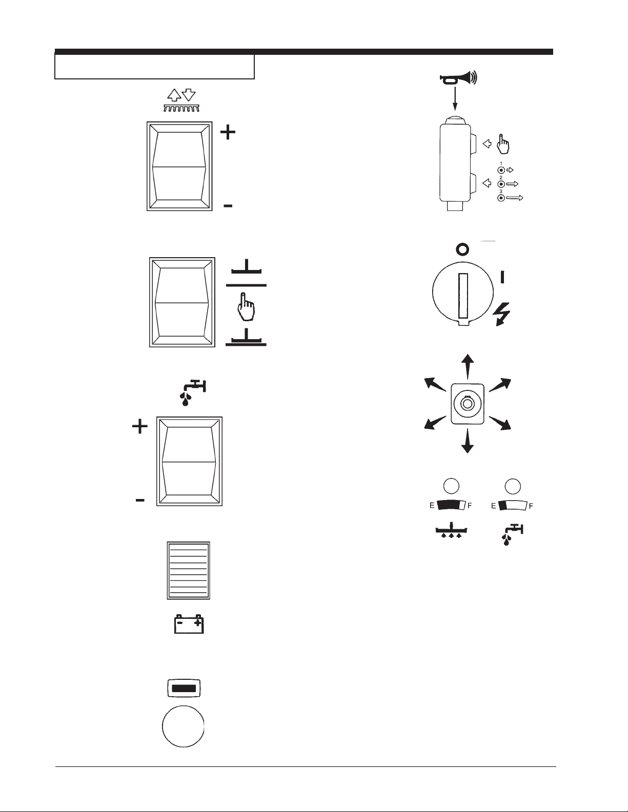
Symbols Used On Scrubtec R
Brush Up/Down
Squeegee
Up/Down
Horn Button
One Touch
Traverse Speed
On/Off Switch
Solution Flow
Switch
Battery Meter
i-Drive
Directional
Guide
Recovery /
Solution LED
LCD Display
Button
Page -6- CLARKE TECHNOLOGY Operator's Manual -
SCRUBTEC R 571 / 571 C / 586SCRUBTEC R 571 / 571 C / 586
SCRUBTEC R 571 / 571 C / 586
SCRUBTEC R 571 / 571 C / 586SCRUBTEC R 571 / 571 C / 586
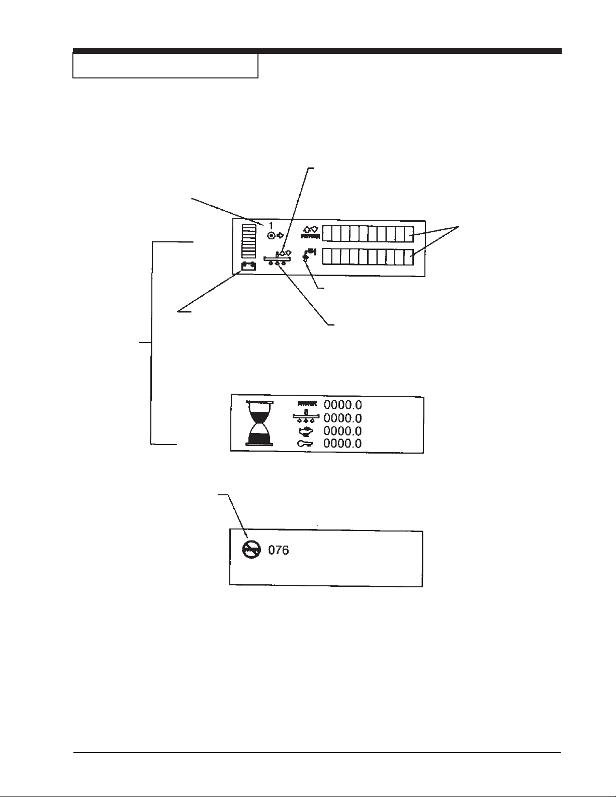
Display Screens For Scrubtec R
Traverse speed indicator
1 = low 0-3 KPH
2 = med 0-5 KPH
3 = high 0-6.4 KPH
SCREEN 1
Screens
Available
to Operator
SCREEN 2
“Battery” blinks when
low voltage occurs.
Position arrow indicating current position
of squeegee (up or down)
Indicators are on,
showing current
settings.
Water “droplets” off when solution is off and
they are flashing when solution is on.
Arrows indicating vacuum status.
They are flashing when vac is on
and off when vac is off.
Example
The Diagnostic only. It will not show unless a fault with
the machine occurs. When the fault happens the icon
and error code will be displayed.
CLARKE TECHNOLOGY Operator's Manual -
SCREEN 3 (Diagnostic)
SCRUBTEC R 571 / 571 C / 586SCRUBTEC R 571 / 571 C / 586
SCRUBTEC R 571 / 571 C / 586 Page -7-
SCRUBTEC R 571 / 571 C / 586SCRUBTEC R 571 / 571 C / 586
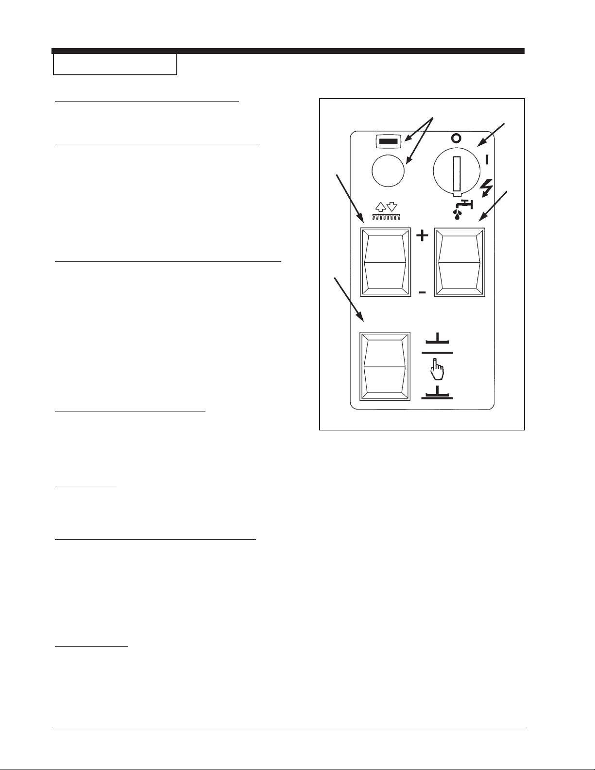
Machine Control Panel
On/Off Key Switch (See figure 1, Item D)
The key switch turns “ON” the power to the control
panel. “O” is the “OFF” and “I” is the “ON”.
Brush Up/Down Switch (See figure 1, Item A)
To lower brush head, push the brush switch in the
down (+) position. To lower the brush head to maximum brush pressure, continue to hold the switch in
the down (+) position until the travel stops. The brush
motors will start and solution will flow (provided the
solution is turned “ON”) when the machine begins to
traverse. To raise the brush head, push the brush
switch in the up (-) position until the brush head travel
stops or desired position is reached.
Squeegee Up/Down Switch (See figure 1, Item B)
The squeegee switch is used to raise and lower the
squeegee and to turn on and off the vacuum motor.
The vacuum motor is turned on when the switch is
placed in the middle or lower position. NOTE: When
the squeegee switch is placed in the lower
position, the vacuum motor will turn on.
To raise the squeegee, place the switch in either the
middle or up position. The middle position is used for
one touch control. The vacuum motor will stop, after a
short delay, when the switch is placed in the up
position.
E
D
A
C
B
Hour Meter (See figure 1, Item E)
The hour meter is located on the front display. You
must toggle screens using LCD display button. The
hour meter indicates the number of hours the machine
has operated. It displays brush motor, vacuum motor,
traverse motor and total key on times.
Battery Meter
The battery meter indicates the relative charge on the
battery pack. The battery meter is located on screen
1 on the front display. See page 7.
Solution Flow Control (See figure 1, Item C)
The solution flow switch regulates the flow of chemical
solution to the floor. To increase the flow, toggle (+).
To decrease the flow, toggle (-). To shut off the
solution, toggle - until no indicators are visible on
display (see figure 2). NOTE: DO NOT run dry!
NOTE: No solution will flow when the machine
does not traverse.
Circuit Breakers
The circuit breaker reset buttons are located on the
back side of the front cover below front display. The
breakers are as follows:
Item A - Main (5 amp)
Item B - Key Switch (5 amp)
Figure 1
Page -8- CLARKE TECHNOLOGY Operator's Manual -
SCRUBTEC R 571 / 571 C / 586SCRUBTEC R 571 / 571 C / 586
SCRUBTEC R 571 / 571 C / 586
SCRUBTEC R 571 / 571 C / 586SCRUBTEC R 571 / 571 C / 586
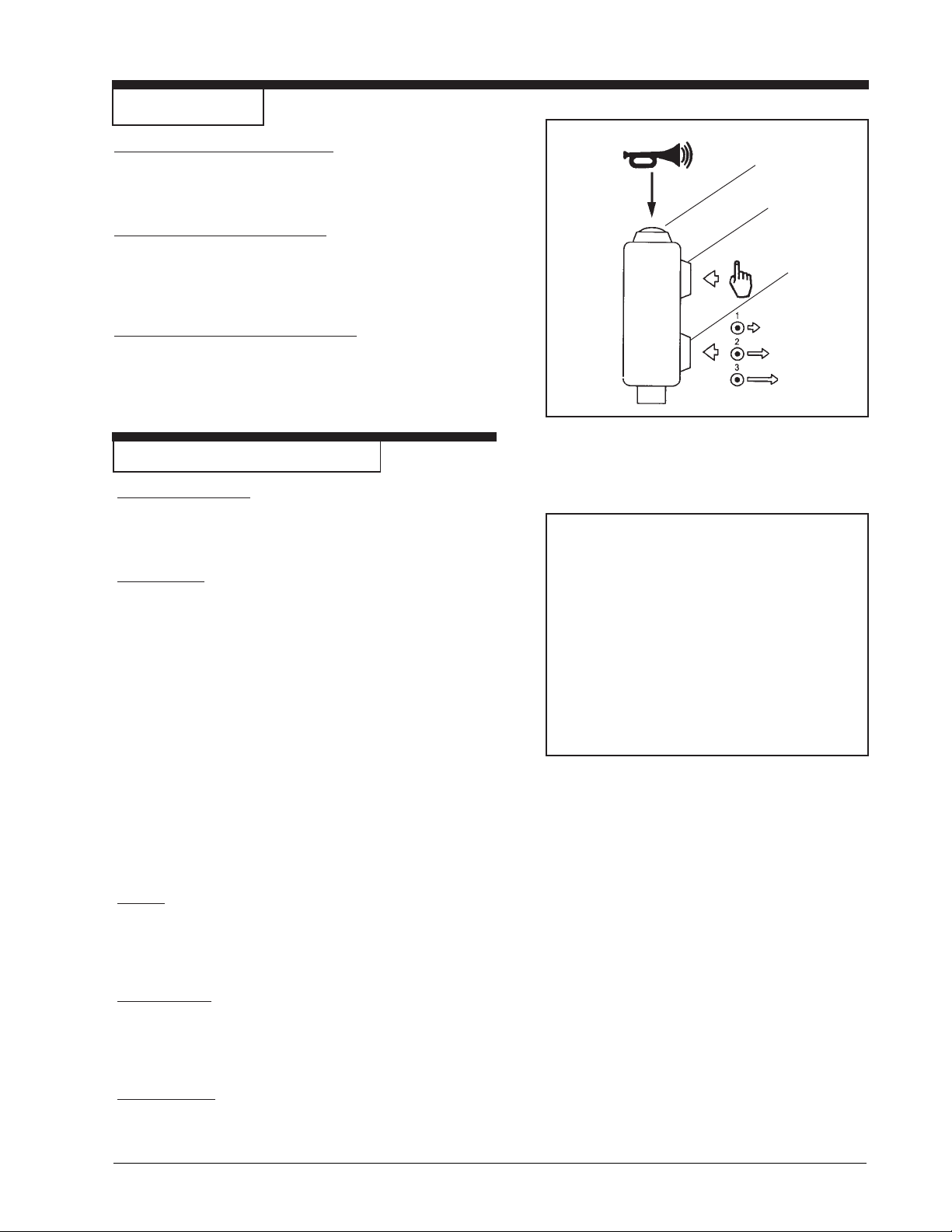
i-Drive Controls
Horn Button (See figure 2, Item A)
The machine is equipped with a horn and is activated by the
red button located on the top of the joystick. The horn will
sound continuously when pressed.
One Touch (See figure 2, Item B)
The one touch button is a green button located on the upper
front of the joystick. NOTE: For more information about the
one touch feature see the section titled “How to Operate the
Machine”.
Speed Selector (See figure 2, Item C)
The speed selector is a black button located on the lower
front of the joystick. Pressing will advance speed range in
the following manner: 1, 2, 3, 2, 1. You may change speeds
while traversing the machine.
Machine Controls and Features
Recovery Tank Float
The Scrubtec R is equipped with a float that shuts the vacuum
off when the recovery tank is full. The squeegee will no longer
pick up water. If this should happen, raise the squeegee and
empty the recovery tank.
A
B
C
Figure 2
The Traverse
The Scrubtec R is equipped with an electronically controlled
traverse system with variable speeds in forward and reverse.
1. To traverse the machine, the power to the machine must
be turned on with the key switch and the operator must
be properly seated. The joystick must be positioned in
either the forward or reverse direction.
2. The traverse speed and direction can be adjusted by
varying the pressure and direction of the joystick.
3. The joystick is very responsive. Simply point it in the
direction you wish to go. NOTE: For initial training, keep
speed setting in 1 and train in an open area.
NOTE: During reverse motion, the squeegee raises and the
solution flow stops automatically. Reverse also reduces
maximum traverse speed.
4. The front wheel always returns to center when you
remove your hand from the joystick.
Brakes
The machine is equipped with an electronic braking system.
The electronic braking is activated automatically when the
operator’s hand is removed from the joystick. NOTE: During
training, you should allow machine to come to a full stop until
you become familiar with stopping distances required.
Parking Brake
The parking brake is activated automatically when the
machine comes to a stop. It disengages automatically when
you begin to traverse. The transaxle is equipped with a
manual brake release. NOTE: Machine will not function when
manual brake release is engaged. See figure 3.
Figure 3
Reverse Alarm
The reverse alarm will sound intermittently and automatically
when the machine is in reverse.
CLARKE TECHNOLOGY Operator's Manual -
SCRUBTEC R 571 / 571 C / 586SCRUBTEC R 571 / 571 C / 586
SCRUBTEC R 571 / 571 C / 586 Page -9-
SCRUBTEC R 571 / 571 C / 586SCRUBTEC R 571 / 571 C / 586
How To Prepare the Machine For Operation
How To Handle the Packed Machine
The machine is packed in a specific package provided on
a pallet so that it can be moved with a forklift.
WARNING: The packages cannot be placed on
top of each other.
How to Unpack the Machine
1. Remove the outer package.
2. The machine is fixed on the pallet with banding
straps and wooden blocks to prevent movement
during shipment. Remove the bands and blocks.
3. The machine is shipped with the batteries already
installed. The machine can be driven off of the
pallet if the operator is thoroughly familiar with its
operation.
4. Remove tie down brackets.
5. Lower the ramp. Release the parking brake and
remove the machine. Avoid violent blows to the
base unit.
6. Keep the pallet for future transport necessities.
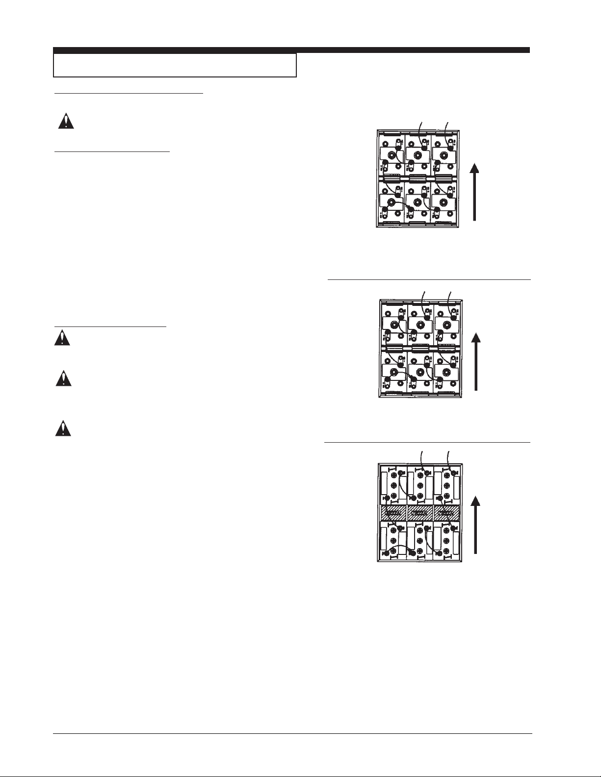
How to Install the Batteries
BA TTERY CONNECTIONS
Front of
machine
370 AH, 6 V olt
(Battery No. 40704A Wet)
(Battery No. 40602A Dry)
Front of
machine
WARNING: The batteries are heavy. Lifting
batteries without help could result in
an injury. Get help to lift the
batteries.
WARNING: Working with batteries can be
dangerous. Always wear eye
protection and protective clothing
when working near batteries. NO
SMOKING!
WARNING: Hydrogen gas is formed during the
charging operation and is explosive.
Only charge batteries in a well
ventilated area with the seat base
lifted.
The batteries are fitted in the battery compartment under
the seat and recovery tank (figure 4). The machine uses
six - 6 volt batteries. They must be handled by using
appropriate lifting equipment suitable for the weight and
for the coupler system. For maintenance and daily
recharge of the batteries, it is necessary to follow all
instructions given by the manufacturer.
For Battery Installation follow these steps (See figure 4):
1. Make sure that the key switch is in the “OFF”
position.
2. Lift and rotate the base support of the seat forward.
3. Lean the seat on it’s restraint cable.
4. Lift the front of the recovery tank and rotate it towards
the rear until it rests on it’s restraint cable.
5. Put the batteries into position and connect the
battery cables as shown in figure 4.
6. Rotate the recovery tank and then carefully rotate it
forward to the normal operating position.
330 AH, 6 V olt
(Battery No. 891384 Wet)
(Battery No. 891385 Dry)
Front of
machine
250 AH, 6 V olt
(Battery No. 881317 Wet)
(Battery No. 881318 Dry)
Three (3) 70222A Spacers
Figure 4
7. Lower the base support of the seat.
NOTE: Charge the batteries before using.
Page -10- CLARKE TECHNOLOGY Operator's Manual -
SCRUBTEC R 571 / 571 C / 586SCRUBTEC R 571 / 571 C / 586
SCRUBTEC R 571 / 571 C / 586
SCRUBTEC R 571 / 571 C / 586SCRUBTEC R 571 / 571 C / 586
How To Prepare the Machine For Operation
Battery Maintenance
The electrical power to operate the machine comes from the
storage batteries. Storage batteries need preventative
maintenance.
WARNING: Working with batteries can be
dangerous. Always wear eye
protection and protective clothing
when working near batteries. NO
SMOKING!
To maintain the batteries in good condition, follow these
instructions:
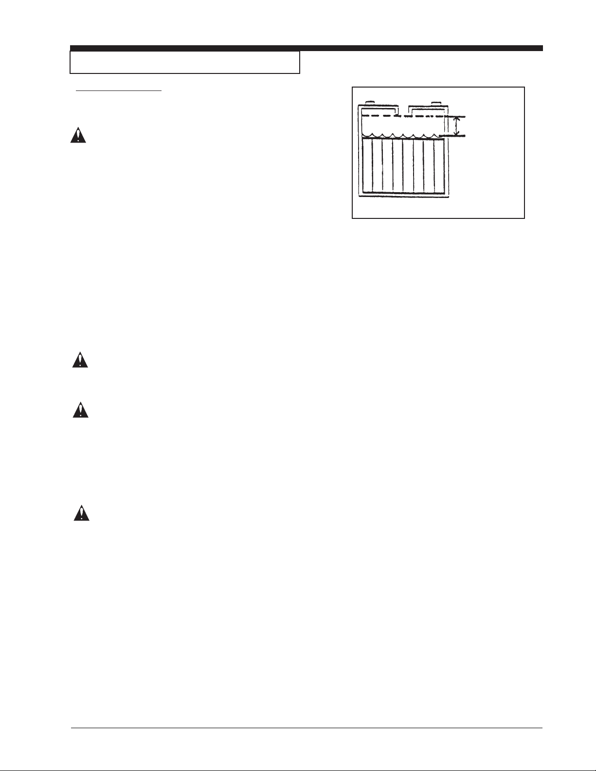
Correct Fill
1. Keep the electrolyte at the correct level. The correct
level is between 1/4” (1/2 cm) below the bottom of the
tube in each cell and above the tops of the plates.
Check the level of the electrolyte each time you charge
the batteries (see figure 5).
NOTE: Check the level of electrolyte prior to charging the
batteries. Be sure the plates in each cell are covered with
electrolyte before charging. Do not top off the cells prior to
charging the battery. Electrolyte expands during charging.
As a result, the electrolyte could overflow from the cells.
Always top off the cells with distilled water after charging.
CAUTION: Irreversible damage will occur to
the batteries if electrolyte does not
cover the plates. Keep the
electrolyte at the correct level.
CAUTION: Machine damage and discharge
across the tops of the batteries can
occur if the batteries are over filled.
Do not fill the batteries up to the
bottom of the tube in each cell.
Wipe any acid from the machine or
the tops of the batteries. Never
add acid to a battery after
installation.
Figure 5
CAUTION: Batteries must be refilled with
distilled water only. Do not use tap
water as it may contain
contaminants that will damage
batteries.
2. Keep the tops of the batteries clean and dry. Keep the
terminals and connectors clean. To clean the top of
the batteries, use a damp cloth with a weak solution of
ammonia or bicarbonate of soda solution. To clean
the terminals and connectors, use a terminal and
connector cleaning tool. Do not allow ammonia or
bicarbonate of soda to get into the batteries.
3. Keep the batteries charged.
CLARKE TECHNOLOGY Operator's Manual -
SCRUBTEC R 571 / 571 C / 586SCRUBTEC R 571 / 571 C / 586
SCRUBTEC R 571 / 571 C / 586 Page -11-
SCRUBTEC R 571 / 571 C / 586SCRUBTEC R 571 / 571 C / 586
How To Prepare the Machine For Operation
How to Charge the Batteries
WARNING: Charging the batteries in an area
without adequate ventilation could
result in an explosion. To prevent
an explosion, charge the batteries
only in an area with good
ventilation.
WARNING: Lead acid batteries generate gases
which could explode. Keep sparks
and flames away from batteries.
NO SMOKING!
To charge the batteries, follow this procedure:
1. Make sure the key switch is in the “OFF” position.
2. Raise the seat base support.
3. Connect the battery charger AC cord to a 15 amp
(min) 120V properly grounded wall receptacle.
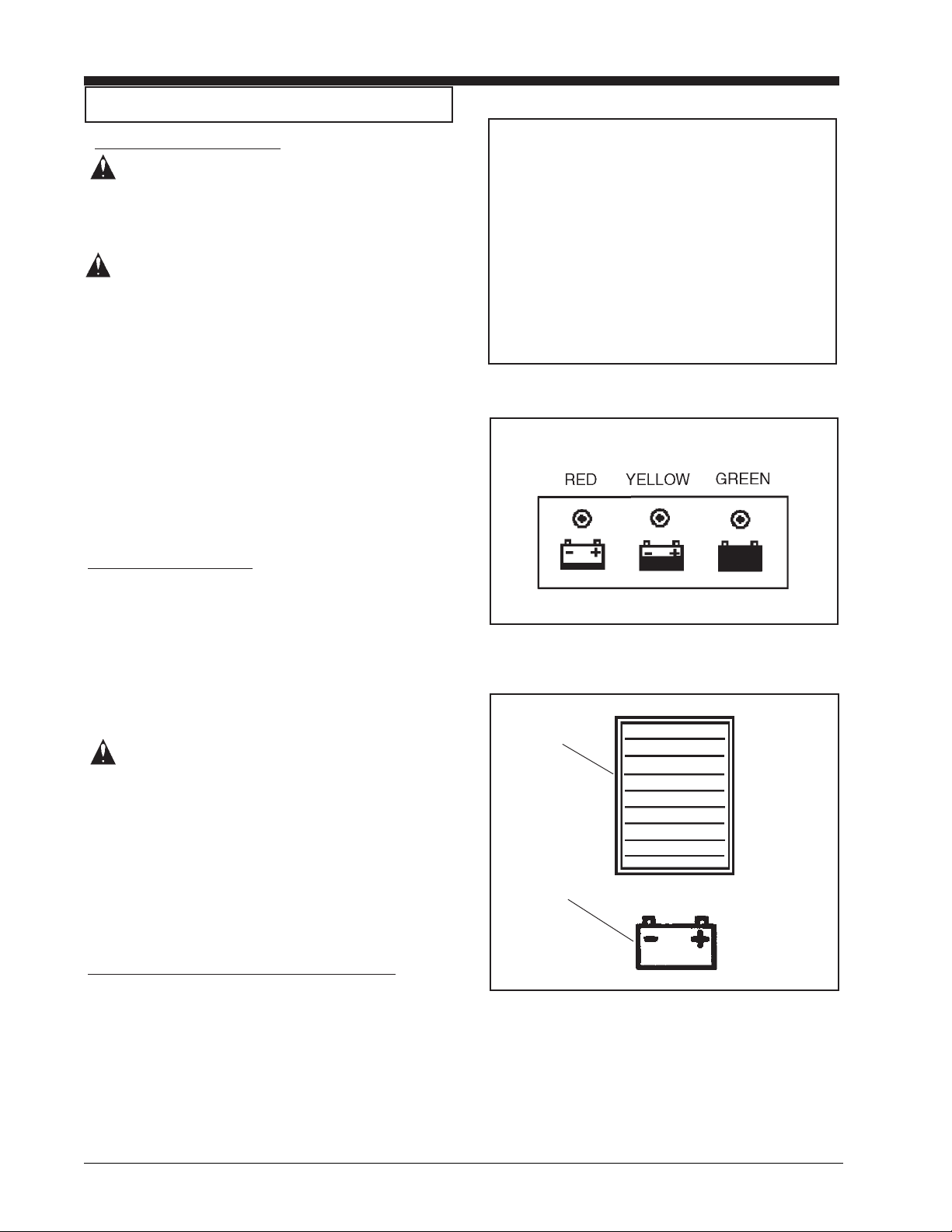
4. Observe indicator light to ensure the charging
process has started (see figure 6, A - Red, B Yellow, C - Green ). For color indications see figure
6A.
Recharging the Batteries
The Scrubtec R comes with an on board charger.
1. Plug into any wall socket and charging is automatic.
A
A
B
Figure 6
B
C
C
2. Observe indicator light to ensure the charging
process has started (see figure 6, A - Red, B Yellow, C - Green ). For color indications see figure
6A.
NOTE: Make sure you plug into a circuit that is not loaded
by other equipment. Wall breakers may be tripped and
no charge will occur.
WARNING: Never charge a GEL battery with an
unsuitable battery charger.
Carefully follow the instructions
given by the manufacturer of the
batteries and battery charger.
NOTE: To prevent permanent damage to the batteries,
avoid their complete discharge. Never leave the batteries
completely discharged, even if the machine is not being
used. When recharging the batteries, keep the base
support of the seat lifted. After every 20 recharging
operations, check the level of the electrolyte and if
necessary top off with distilled water.
Level Indicators for the Charge of the Batteries
The battery meter ( see figure 7) on the control panel has
a digital read out with 10 fixed positions (A) and also a
blinking indicator (B). The bars that appear on the display
show the approximate charge level with icon (blinking)
discharged battery.
NOTE: A few seconds after the voltage reads 32V it will
start blinking. The brush motors will then automatically
switch off.
Figure 6A
A
B
Figure 7
Page -12- CLARKE TECHNOLOGY Operator's Manual -
SCRUBTEC R 571 / 571 C / 586SCRUBTEC R 571 / 571 C / 586
SCRUBTEC R 571 / 571 C / 586
SCRUBTEC R 571 / 571 C / 586SCRUBTEC R 571 / 571 C / 586

How To Prepare the Machine For
Operation
How To Install the Squeegee
To install the squeegee onto the machine, follow this
procedure:
1. The squeegee assembly has a break away feature
that is also used for mounting the squeegee. Loosen
the knobs on the squeegee (figure 8). Slide the stud
into the slotted hole in the support frame on the
machine.
2. Attach the vacuum hose cuff to the squeegee hose
fitting (see figure 9).
3. Tighten knobs. NOTE: Do not overtighten or break
away feature is lost and damage may occur.
NOTE: To prevent damage to the squeegee or machine, the
squeegee was designed to break away from the machine.
If the squeegee is impacted and it breaks away from the
machine, simply reinstall it by following step 1-3.
How to Adjust the Squeegee
During operation, the rear squeegee blade should have a
constant 3/16” minimum flare along the entire squeegee
blade (see figure 10).
1. The squeegee body can be tilted to adjust the
squeegee blade flare in the middle to match the flare
on the ends. To adjust the tilt, loosen the adjusting
bolt located on the left and right side of the squeegee
(see figure 9).
2. Press down on the squeegee until both sets of guide
wheels contact floor.
3. After making adjustments, retighten the screw(s).
NOTE: It is important that the right and left wheels are
contacting the floor in order for the squeegee to work.
Figure 8
Figure 9
Figure 10
3
/16” minimum
NOTE: As the rear squeegee blade wears, it can be rotated
and/or flipped to obtain four good edges before having to
change blades.
CLARKE TECHNOLOGY Operator's Manual -
SCRUBTEC R 571 / 571 C / 586SCRUBTEC R 571 / 571 C / 586
SCRUBTEC R 571 / 571 C / 586 Page -13-
SCRUBTEC R 571 / 571 C / 586SCRUBTEC R 571 / 571 C / 586

How To Prepare the Machine For
Operation
How To Change or Rotate Brushes on Cylindrical Brush
Head
To install or rotate brushes on the cylindrical brush head:
1. Raise the brush deck and turn the key switch “OFF”.
2. Raise the brush skirt and pull out to remove. See
figure 11.
3. Remove thumb screw from brush door. See figure 12.
4. Lower door approximately 12 mm and slide door and
hub assembly from brush. See figure 13.
5. Slide brush off hub at opposite end. See figure 14.
6. Rotate brush or replace.
7. Slide brush on drive hub and insert door and hub
assembly into brush core.
8. Raise door and install thumb screw.
9. Place side skirt on retainer pins and lower in place.
10. Brushes should be rotated after every 20 hours of use.
Figure 11
Figure 12
Page -14- CLARKE TECHNOLOGY Operator's Manual -
Figure 13
Figure 14
SCRUBTEC R 571 / 571 C / 586SCRUBTEC R 571 / 571 C / 586
SCRUBTEC R 571 / 571 C / 586
SCRUBTEC R 571 / 571 C / 586SCRUBTEC R 571 / 571 C / 586

How To Operate The Machine
How to Operate the i-Drive Controls
The following controls are located on the joystick:
1.
Horn : The horn is a red button located on the top of the
joystick (figure 15, item A). NOTE: The horn sounds
continuously when pressed and intermittent and
automatic in reverse.
2.
One Touch: The one touch button is a green button located
on the upper front of the joystick (figure 15, item B). NOTE:
For more information about the one touch control see
below.
3.
Speed Selector: The speed selector is a black button
located on the lower front of the joystick (figure 15, item C).
Horn Operation
The horn is a continuous tone when pressing the horn button. In
reverse the horn pulses automatically.
One Touch Operation
One touch cleaning is a feature on the Scrubtec R. The factory
defaults for this setting are two bars of brush pressure and four
bars for solution flow and squeegee in the down position.
1. Press and release the green button for all cleaning
functions to begin.
A
B
C
Figure 15
2. The squeegee and brush head lower to the floor and the
vacuum starts.
3. The brushes and solution will begin only when you begin to
traverse.
4. The cleaning will be at the factory default settings, however
you can reprogram these settings to your specifications.
See “Reprogramming One Touch” section below.
5. To end cleaning process, press the green button again and
solution will stop; brushes will raise; after a short delay
squeegee will raise; and the vacuum motor will turn off.
NOTE: It is intended that this be done while traversing. If you
stop and do it, some solution can be left on the floor.
Reprogramming One Touch
If you do not want to use the factory default settings, you may
reprogram the setting by following the procedures below:
1. Place the machine in the desired scrub condition by using
the one touch and / or individual switches.
2. Press and hold the green one touch button until you hear a
single beep from the machine then release the button.
NOTE: The time required should be approximately 5
seconds.
3. When you activate or deactivate the one touch, it will now be
set to your preference for cleaning. These settings will
remain until you disconnect power or reprogram them.
NOTE: When programming one touch, be sure squeegee
is in automatic (middle) position, otherwise you may
program squeegee either up or down all the time.
CLARKE TECHNOLOGY Operator's Manual -
SCRUBTEC R 571 / 571 C / 586SCRUBTEC R 571 / 571 C / 586
SCRUBTEC R 571 / 571 C / 586 Page -15-
SCRUBTEC R 571 / 571 C / 586SCRUBTEC R 571 / 571 C / 586

How To Operate The Machine
How to Return One Touch to Factory Default Settings
To restore the factory settings, follow the procedures below:
1. Press and hold the green one touch button (figure 15, B)
until you hear a
The time required for this will be approximately 10
seconds.
2. The settings should be returned to 4 bars of solution and
2 bars of brush pressure. NOTE: The squeegee vac
switch must be in the middle position for default
settings to work.
Directional Control (see figure 16, A and B)
The Scrubtec R is equipped with a joystick for controlling
speed and direction of the machine. Simply point the
joystick in the direction you want the machine to go (figure
16, A). This is true for both forward and reverse directions.
The speed and direction are directly proportional to the
position of the joystick. If you want to go slow and straight,
apply a slight amount of pressure to the joystick in the
forward direction. For more speed, move the joystick
further in direction you wish to travel.
double beep from the machine. NOTE:
Forward Left
(T op V iew)
A
B
Forward Right
NOTE: See example in figure 16, B - the joystick is
positioned to where the machine will go in the forward-right
direction.
How to Move the Machine Without Power (see figure 17)
1. Engage manual override on brake (see page 9, “Parking
Brake”).
2. Remove foot plate and 4 screws.
3. Using the knob, turn shaft on motor in direction you wish
to turn machine.
4. Slowly push machine to desired location. NOTE: If you
attempt to push machine too fast it will limit top speed.
If this happens, stop and restart.
5. After moving machine, disengage manual brake
override. NOTE: Machine will not function if override is
engaged.
Reverse Left Reverse Right
Figure 16
Page -16- CLARKE TECHNOLOGY Operator's Manual -
Figure 17
SCRUBTEC R 571 / 571 C / 586SCRUBTEC R 571 / 571 C / 586
SCRUBTEC R 571 / 571 C / 586
SCRUBTEC R 571 / 571 C / 586SCRUBTEC R 571 / 571 C / 586

How To Operate the Machine
Seat Adjustment (Standard)
The seat cannot be adjusted.
Seat Adjustment (Deluxe)
The optional deluxe seat is adjustable in three ways:
1. The seat can be adjusted to the forward/backward
position by using the lever on the lower right side of the
seat . Moving the lever will allow the seat to slide into
the preferred position. See figure 18.
2. To adjust the angle of the back support portion of the
seat, turn the lever located in the middle right position
of the seat. Turning this clockwise will make the seat
more vertical. Turning the knob counterclockwise will
tilt the seat back.
See figure 19, A.
3. To adjust the suspension of the seat for operator
comfort, use the lever on the side of the back support
section of the seat. This has three positions. The
upper position is for light weight operators. The
middle position is for medium weight operators. The
bottom position is for heavy weight operators. See
figure 20, B. NOTE: The lever must be pressed firmly
to change positions.
Figure 18
Figure 19
CLARKE TECHNOLOGY Operator's Manual -
SCRUBTEC R 571 / 571 C / 586SCRUBTEC R 571 / 571 C / 586
SCRUBTEC R 571 / 571 C / 586 Page -17-
SCRUBTEC R 571 / 571 C / 586SCRUBTEC R 571 / 571 C / 586

How To Operate the Machine
How to Read the Battery Meter (see figure 20, A)
The battery meter is an indicator on the LCD display. This
indicator is on the LCD display on the front of the machine.
It has 10 bars with 10 bars visible indicating a full charge.
As you run the machine the bars will begin to lower. The
“Battery Icon” (B) will begin to flash to indicate you are
reaching the end of charge.
NOTE: If you continue to run the brushes they will shut
down to protect the batteries from over discharging.
NOTE: Run times will vary depending on machine
variables, battery size, brush pressure and floor type,
etc.
How to Change Displays Screens on the LCD Module
The LCD display has three screens. Two of them can be
accessed at any time the key is on. The first screen
shows the machine status and the second screen shows
the four hour meters (figure 20).
The two screens that can be viewed by the operator can be
accessed via the display button (figure 21) on the control
panel to the left of the key switch. Pressing this button
toggles the display between the available screens.
SCREEN 1
A
B
SCREEN 2
Figure 20
The third screen is for diagnostics only. This screen
displays any errors that might occur or if the system
diagnostics finds something wrong. When the diagnostic
screen comes up, refer to the trouble shooting guide for
suitable action to resolve the error code.
Figure 21
Page -18- CLARKE TECHNOLOGY Operator's Manual -
SCRUBTEC R 571 / 571 C / 586SCRUBTEC R 571 / 571 C / 586
SCRUBTEC R 571 / 571 C / 586
SCRUBTEC R 571 / 571 C / 586SCRUBTEC R 571 / 571 C / 586

How To Operate the Machine
How to Operate the Squeegee and the Vacuum
Motor
The squeegee wipes the floor while the vacuum motor
removes the dirty solution from the floor. To operate the
squeegee, follow this procedure:
1. To lower the squeegee and start the vacuum motor,
press the squeegee up/down switch to the down
position (figure 22). NOTE: The vacuum motor
will start immediately when the down position
of the switch is pressed, and the squeegee will
lower.
2. To raise the squeegee, press the squeegee up/
down switch to the up position (figure 22). The
squeegee will then raise and the vacuum motor will
shut off after short delay NOTE: The center
position of the squeegee up/down switch is for
use with one touch control.
NOTE: The squeegee will rise automatically when
traversing in reverse during scrubbing operations.
How to Operate the Solution Flow
The solution is used to loosen and remove dirt from the floor.
The amount of solution applied can be adjusted to five
different levels to accommodate many different floor
conditions. These different levels are shown on the LCD
display on the front of the machine. To adjust the amount
of solution applied, use the Solution Flow Switch (figure 23).
NOTE: There are five different settings on the display
and they come on two bars at a time. See figure
24, A.
Figure 22
To increase solution flow:
1. Press the “ + ” side of the switch (figure 23).
2. Press and hold the “ + ” switch to achieve the desired
level of solution flow.
To decrease solution flow:
.
1. Press the “ - “ side of the switch (figure 23).
2. Press and hold the “ - “ side of the switch to achieve the
desired level of solution flow.
How to Operate the Brush Pressure
The brushes are used to supply agitation for the solution,
which improves the cleaning process. The amount of brush
pressure applied can be adjusted to five different levels to
accommodate many different floor conditions. These
different levels are shown on the LCD display on the front of
the machine (figure 24, B). To adjust the amount of brush
pressure, use the brush up/down switch (figure 25).
To increase brush pressure:
1. Press the “ + ” side of the switch (figure 25).
2. Press and hold the “ + ” switch to achieve the desired
level of pressure.
To decrease brush pressure:
.
1. Press the “ - “ side of the switch (figure 25).
Figure 23
B
A
Figure 24
2. Press and hold the “ - “ side of the switch to achieve the
desired level of pressure.
CLARKE TECHNOLOGY Operator's Manual -
SCRUBTEC R 571 / 571 C / 586SCRUBTEC R 571 / 571 C / 586
SCRUBTEC R 571 / 571 C / 586 Page -19-
SCRUBTEC R 571 / 571 C / 586SCRUBTEC R 571 / 571 C / 586
Figure 25

How To Operate the Machine
How to Fill the Solution Tank
The solution tank fill port is located at the left side of the
machine (see figure 26). To fill the solution tank, follow
this procedure:
1. Turn the key switch to the “OFF” position.
2. Remove lid.
3. Add a cleaning chemical to the solution tank. For
the correct amount of chemical, follow the directions
shown on the container. NOTE: Excess foam in
the recovery tank could damage the vacuum
motor, so use only the minimum amount of
detergent necessary.
WARNING: Always use low foam detergent.
To avoid the production of foam,
before starting to clean, put a
minimum quantity of antifoam
liquid into the recovery tank.
NEVER USE PURE ACID.
4. Fill the solution tank with clean water (see figure 26).
5. After filling the solution tank, replace the solution
tank lid.
WARNING: Water solutions or cleaning
materials used with this type of
machine can leave wet areas on
the floor surface. These areas
can cause a dangerous condition
for the operator or other persons.
Always put CAUTION signs near
the area you are cleaning.
WARNING: Machines can ignite flammable
materials and vapors. Do not use
with or near flammables such as
gasoline, grain dust, solvents and
thinners. Only use a cleaning
concentration recommended by
the chemical manufacturer.
WARNING: ALTO recommends a maximum
water temperature of 120°F
(49°C).
Figure 26
Operating the Machine
NOTE: Before scrubbing with the machine, become
familiar with the operations and handling of the machine.
Run the machine at the lowest traverse speed. Use the
machine in an area that has no furniture or objects until
you can do the following:
1. Traverse the machine in a straight direction, forward
and backward.
2. Stop the machine safely.
3. Turn the machine both left and right and return to a
straight direction.
o
4. Turn a 180
Page -20- CLARKE TECHNOLOGY Operator's Manual -
turn where one rear wheel just pivots.
SCRUBTEC R 571 / 571 C / 586SCRUBTEC R 571 / 571 C / 586
SCRUBTEC R 571 / 571 C / 586
SCRUBTEC R 571 / 571 C / 586SCRUBTEC R 571 / 571 C / 586

How To Operate the Machine (cont.)
To traverse the machine follow this procedure:
1. Sit on the driver seat.
traverse if the operator is not properly seated.
NOTE: The machine will not
2. Turn the key switch to the “ON” position.
3. Raise the brush to the highest position.
4. Raise the squeegee.
6. Gently press on the joystick in the direction you
want to travel. The machine will begin to move.
7. To change the speed of the machine move the
joystick. Move it in the direction you want to travel.
8. To stop, release pressure on the joystick and allow
it to re-center.
9. To travel in reverse, move the joystick in the reverse
position. NOTE: Keep the joystick pointed in
the direction you wish to go.
10. To stop, release the joystick.
11. To turn the machine, move the joystick in the
direction you want to turn.
12. When you stop the machine, turn the key switch
“OFF” and remove the key.
Figure 27
Do These Procedures When You Begin Your Work
Period
1. Make sure the key switch is in the “OFF” position.
2. Disconnect AC power from battery charger (follow
charger instructions).
3. Make sure the filter screen (1) to the vacuum motor
is clean and installed properly in the recovery tank
(see figure 27).
4. Make sure the recovery tank lid is in place and has
been tightened (see figure 28).
5. Close and secure the lower cleaning port cover on
the recovery tank.
6. Make sure that the plug in the recovery drain hose
is in place and has been tightened (see figure 29).
7. Make sure that the brushes/pads are in position
and installed correctly.
8. Make sure the brush housings are in position on
the brush head.
9. Check the installation of the squeegee and
squeegee hose.
Figure 28
Figure 29
CLARKE TECHNOLOGY Operator's Manual -
SCRUBTEC R 571 / 571 C / 586SCRUBTEC R 571 / 571 C / 586
SCRUBTEC R 571 / 571 C / 586 Page -21-
SCRUBTEC R 571 / 571 C / 586SCRUBTEC R 571 / 571 C / 586

How To Operate the Machine
How to Clean a Floor
WARNING: Water solutions or cleaning materials
For one touch automatic cleaning follow this procedure:
1. Turn the key switch to the “OFF” position.
2. Put the water and a cleaning chemical in the solution
tank.
3. Sit on the driver seat. NOTE: The machine will not
traverse if the operator is not properly seated.
4. Turn the key switch “ON”. NOTE: The key switch turns
on the battery and LED screen displays, which shows
the machines condition.
5. The machine has a one touch button on the joystick
(see figure 30) that is preset for brush pressure and
solution flow. Momentarily depress the one touch
button if you wish to use these settings. NOTE: If this is
not the settings that you desire see page 15 or one
touch operation.
For manual control of cleaning process, follow these
procedures:
1. Turn the key switch to the “OFF” position.
2. Put the water and a cleaning chemical in the solution
tank.
3. Sit on the driver seat. NOTE: The machine will not
traverse if the operator is not properly seated.
4. Turn the key switch “ON”. NOTE: The key switch turns
on the battery and LED screen displays, which shows
the machines condition.
5. Lower the squeegee. NOTE: The vacuum motor will
turn on when the squeegee up/down switch is placed
in the lower position.
6. Lower the brush head until it reaches the full stroke
down. NOTE: The brushes will start rotating only
when the machine begins to traverse.
7. Reset the solution flow valve by using the + / - solution
switch. NOTE: The solution will flow only if the
machine is moving forward.
8. Press the joystick in the desired direction/position.
After the joystick is pressed the machine will begin to
move and the brushes will start to rotate and solution
will begin to flow.
9. After a few feet of scrubbing, check to see that the
amount of solution being applied is correct and that the
squeegee is picking up water and drying the floor.
Make adjustments as required.
10. Once the machine is set properly continue to scrub until
the solution low indicator comes on or until you run out
of solution.
WARNING: If the machine develops operating
NOTE: When making multiple passes across the floor,
overlap the brush cleaning path approximately 2 inches (5
cm) of the area already cleaned by the brush.
NOTE: During most cleaning procedures, apply and remove
the solution in one operation.
used with this type of machine can
leave wet areas on the floor surface.
These areas can cause a dangerous
condition for the operator or other
persons. Always put CAUTION signs
near the area you are cleaning.
problems while working, remove your
hand from the joystick. After
resolving the problem, continue
working.
Figure 30
Page -22- CLARKE TECHNOLOGY Operator's Manual -
SCRUBTEC R 571 / 571 C / 586SCRUBTEC R 571 / 571 C / 586
SCRUBTEC R 571 / 571 C / 586
SCRUBTEC R 571 / 571 C / 586SCRUBTEC R 571 / 571 C / 586

How To Operate the Machine
How to Clean a Very Dirty Floor
To clean a very dirty floor, follow this procedure:
1. Apply solution to the floor.
2. Do not lower the squeegee. This will keep the vacuum
motor off.
3. Lower the brush or pad and scrub the floor.
4. Scrub the floor again with additional solution and
lower the squeegee.
5. Pick up all the solution with the squeegee.
Do These Procedures When You End Your Work Period
Having finished the job and before any type of maintenance
is done, follow these procedures:
For one touch cleaning shut down process, press and
release the one touch button.
For manual shut down follow these procedures:
1. Turn the solution flow off by decreasing the flow to its
minimum position.
2. Press the brush up/down switch to the up position
until the brush head has reached its up most position.
3. Place the squeegee up/down switch in the up position
to raise the squeegee and allow the vacuum motor to
continue to run. The vacuum motor will run for another
20 seconds and then place the squeegee up/down
switch to the up position. This will shut the vacuum
motor off.
4. Take the machine to a water drain.
5. Turn the key switch “OFF”.
6. Remove the drain hose from the holding hook.
Figure 31
7. Put the end of the hose over a drain or bucket.
8. Turn the valve housing to the left (see figure 31).
9. To open the valve completely, turn the housing fully to
the left. Pull the housing off of the valve.
10. Empty the recovery tank. NOTE: When hose is
lowered below water level, water will flow.
WARNING: Use gloves to protect your hands
from contact with dangerous
solutions when preforming the steps
listed above.
CLARKE TECHNOLOGY Operator's Manual -
SCRUBTEC R 571 / 571 C / 586SCRUBTEC R 571 / 571 C / 586
SCRUBTEC R 571 / 571 C / 586 Page -23-
SCRUBTEC R 571 / 571 C / 586SCRUBTEC R 571 / 571 C / 586

How To Operate the Machine
11. Rinse the tank. Put clean water in the tank through
the opening at the top. Be careful not to allow
water into the vacuum intake tube (with screen).
12. If the tank or drain hose has an obstruction, use
water pressure to flush the tank or hose. Put the
water hose into the drain hose.
13. Leave the tank and drain plug removed to air dry.
14. Check the squeegee blade. Use a cloth to clean
the squeegee blade. If the squeegee blade is
damaged or worn, turn or replace the blade.
NOTE: To avoid damage to the squeegee, the
squeegee must be lifted when the machine is not in
operation.
15. Take off the brushes and clean them with a jet
stream of water.
16. Use a clean cloth and wipe the surface of the
machine.
17. Check the batteries and add distilled water as
needed. The correct level is between ¼” (½ cm)
below the bottom of the tube in each cell and above
the tops of the plates. See the instructions in the
section of this book called “Battery Maintenance”.
CAUTION: Tap water may contain
contaminants that will damage
batteries. Batteries must be
refilled with distilled water only.
WARNING: Lead acid batteries generate
gases which can cause an
explosion. NO SMOKING.
Always wear eye protection and
protection clothing when
working near batteries.
18. Charge the batteries. See the instructions in the
section of this book called “How to Charge the
Batteries”.
Page -24- CLARKE TECHNOLOGY Operator's Manual -
SCRUBTEC R 571 / 571 C / 586SCRUBTEC R 571 / 571 C / 586
SCRUBTEC R 571 / 571 C / 586
SCRUBTEC R 571 / 571 C / 586SCRUBTEC R 571 / 571 C / 586

Maintenance
Maintenance To Be Done Every Week
WARNING: Maintenance and repairs must be
done by authorized personnel
only. Always empty the solution
tank and the recovery tank before
doing any maintenance. Keep all
fasteners tight.
WARNING: Always wear eye protection and
protective clothing when working
near batteries. NO SMOKING! Do
not put tools or other metal
objects across the battery
terminals or the tops of the
batteries.
CAUTION: To prevent damage to the
machine, and discharge across
the tops of the batteries, do not fill
the batteries above the bottom of
the tube in each cell. Wipe any
acid from the machine or the tops
of the batteries. Do not add acid
to batteries after installation.
Battery Inspection and Cleaning
1. Turn the key switch to the “OFF” position.
2. To inspect batteries, rotate seat support forward.
Lift and rotate recovery tank. Be sure the recovery
tank is empty before lifting.
Figure 32
3. Disconnect the batteries. Use a cloth and a solution
of ammonia or bicarbonate of soda to wipe the top of
the batteries. Clean the battery terminals. Reconnect
the batteries. See the instructions in the section of
this book called “Battery Maintenance”.
4. When battery inspection is completed, close the
recovery tank. Rotate the seat support back to the
operating position.
Cleaning the Recovery Tank and Filter
1. Turn the key switch to the “OFF” position and set the
parking brake.
2. Empty the recovery tank using the flexible drain
hose by unscrewing the knob and taking off the
plug (see figure 32).
3. If the machine is equipped with the optional cleanout port, open the lower cleaning port cover by
unscrewing the four knobs (see figure 33). NOTE:
Make sure that the tank is empty first.
4. Rinse the tank and clean the drain plug.
Figure 33
CLARKE TECHNOLOGY Operator's Manual -
SCRUBTEC R 571 / 571 C / 586SCRUBTEC R 571 / 571 C / 586
SCRUBTEC R 571 / 571 C / 586 Page -25-
SCRUBTEC R 571 / 571 C / 586SCRUBTEC R 571 / 571 C / 586

Maintenance
5. Clean the hose fitting in the recovery tank and
spray water down the squeegee hose to clean
out debris.
6. Reattach the squeegee hose.
Cleaning the Solution Tank and Filter
1. Move the machine so that the solution tank filter
assembly is located directly over a floor drain.
2. Turn the key switch to the “OFF” position.
3. Clean inside the solution tank with a jet stream
of water.
7. Close the solution flow valve.
8. Clean the filter inside the housing and reinstall on
machine.
Manually Draining the Solution Tank
1. Remove sight gauge hose from top connector
(see figure 34).
Figure 34
2. Rotate lower fitting to allow drain hose to rest
over drain.
3. Drain solution tank (see figure 35).
Vac Assisted Solution Tank Drain
1. Remove vacuum hose from squeegee plate.
2. Turn vac on.
3. Remove and place solution hose into vac hose
until washer rest against hose cuff.
NOTE: Using vac assist will help to rinse recovery
tank. This will help to reduce cleanup and
maintenance times.
Squeegee Maintenance
Clean the squeegee with a jet stream of water and a
damp cloth. Inspect the front and rear squeegee
blades for wear. Readjust or replace if necessary.
Front Squeegee Blade Replacement
To replace the front squeegee blade, follow this
procedure:
1. Remove the squeegee assembly from the
machine.
Figure 35
2. Remove clamp and front squeegee blade.
3. Install new front squeegee blade and reinstall
clamp.
4. Replace squeegee on machine.
Page -26- CLARKE TECHNOLOGY Operator's Manual -
SCRUBTEC R 571 / 571 C / 586SCRUBTEC R 571 / 571 C / 586
SCRUBTEC R 571 / 571 C / 586
SCRUBTEC R 571 / 571 C / 586SCRUBTEC R 571 / 571 C / 586

Maintenance
Rear Squeegee Blade Replacement
If the rear squeegee blade is worn and does not dry
the floor well, follow this procedure:
1. Remove the squeegee assembly from the
machine.
2. Remove the squeegee blade and inspect it.
3. Rotate the squeegee blade to obtain a new
cleaning edge. Replace if necessary.
4. Reinstall the squeegee blade.
5. Reinstall the squeegee assembly on the
machine.
6. Readjust the settings on the squeegee as
required (see “How to Adjust Squeegee”).
Squeegee Maintenance
The squeegee blade may be rotated for longer life.
Keep sharp corner on floor for best cleaning
results. See figure 36. To rotate follow this
procedure:
Figure 36
1. Remove Clamp.
2. Remove blade and rotate to new edge.
3. Replace squeegee.
4. Replace clamp.
Cleaning the Vacuum Hoses
Make sure the squeegee is over a suitable drain.
1. Use a garden hose to flush through the
recovery hoses.
2. Side Squeegee - Position garden hose to the
squeegee side of the hose and flush
thoroughly.
3. Recovery Hose - Position garden hose
inside recovery tank. NOTE: Do not place
hose in vacuum intake (see figure 37),
damage will occur.
Re-center Front Wheel
If the front wheel gets out of adjustment and the
machine does not drive straight when the joystick
is pointed forward, follow this procedure:
Figure 37
Figure 38
1. Remove 4 screws holding foot plate to solution
tank (see figure 38).
2. Locate two black wires tied together and
marked “reset sw” (see figure 39).
CLARKE TECHNOLOGY Operator's Manual -
SCRUBTEC R 571 / 571 C / 586SCRUBTEC R 571 / 571 C / 586
SCRUBTEC R 571 / 571 C / 586 Page -27-
SCRUBTEC R 571 / 571 C / 586SCRUBTEC R 571 / 571 C / 586
Figure 39

Maintenance
3. Using the joystick, position the front wheel
straight by doing one of the following:
a) Using black indicator marks on steering
system, realign front wheel (see figure 40).
b) Place front wheel straight by visually
estimating it’s position (see figure 41).
4. Hold joystick in corrected position and
connect black wires together and key off the
machine (see figure 42).
5. Disconnect black wires.
6. Key machine on. If machine drives straight,
then proceed to step 7. If not, then repeat
steps 2-5.
7. Replace foot plate and screws.
8. Key machine on.
Figure 40
Figure 41
Page -28- CLARKE TECHNOLOGY Operator's Manual -
Figure 42
SCRUBTEC R 571 / 571 C / 586SCRUBTEC R 571 / 571 C / 586
SCRUBTEC R 571 / 571 C / 586
SCRUBTEC R 571 / 571 C / 586SCRUBTEC R 571 / 571 C / 586

HOW TO CORRECT PROBLEMS IN THE MACHINE
PROBLEM CAUSE ACTION
Insufficient water onto the brushes
The machine does not clean
satisfactorily
The squeegee does not dry the floor
The solution flow is not set
There is no water in the solution tank.
The solution filter is dirty.
A circuit breaker has tripped.
Insufficient flow.
The brushes are worn.
Need to use a different kind of brush/pad
The squeegee is dirty.
Recovery drain hose is not closed.
The suction hoses need to be cleaned.
The squeegee blades are worn.
Make sure the solution flow is set.
Fill the solution tank.
Clean the solution filter.
Reset the circuit breaker.
Increase flow with solution switch.
Check the brushes and replace if necessary.
(the brushes have to be replaced when the
bristles reach approximately .59 inches (15mm
height.)
Use a different kind of brush. For cleaning
operations on floors where the dirt proves to be
particularly resistant, we recommend using special brushes. See Accessories page.
Clean the squeegee.
Close the drain plug.
Clean the vacuum hoses. See “Routine Maintenance” section.
Replace/ or rotate the squeegee blades. See
“Routine Maintenance” section.
The vacuum motor does not function
The machine does not start
The brush motors do not work
WARNING: To avoid damage to the
floor, the motor starts only when the
machine is traversing.
The recovery tank is full.
The squeegee up/down switch in not in the
low or middle position.
The operator is not properly seated.
The key is not in the “ON position”.
The charger is still connected.
The batteries are not charged or not con-
nected properly.
The circuit breaker has tripped.
The brush head unit is not down.
The batteries are not charged or not con-
nected properly.
Poor electrical connection at the brush head
unit.
Drain recovery tank.
Put the squeegee in the low or middle position
or reprogram “one touch”.
The operator must be properly seated in the
driving position.
Turn the key to the “ON” position.
Remove the A/C cord from the wall.
Check to make sure the batteries are con-
nected properly and charge if necessary.
Reset the circuit breaker.
Put the brush head unit down.
Check to make sure the batteries are con-
nected properly and charge if necessary.
Connect the electrical connection at the brush
head unit.
CLARKE TECHNOLOGY Operator's Manual -
SCRUBTEC R 571 / 571 C / 586SCRUBTEC R 571 / 571 C / 586
SCRUBTEC R 571 / 571 C / 586 Page -29-
SCRUBTEC R 571 / 571 C / 586SCRUBTEC R 571 / 571 C / 586

Scrubtec R
Common Error Codes
ERROR
CODE
1500
1501
1507
1600
3100
3101
3102
3103
3104
3105
7600
7602
7603
CAUSE
Check brake and wiring for
short circuit.
High battery voltage.
Probable short circuit of
output device.
Open circuit on brush motors
or brush motor wiring.
Brush motor overload.
Possible short circuit on
brush motors or wiring.
ACTION
Make sure manual override is not
engaged.
Poor or corroded connection to the
battery.
Check the traction, brush and vac motor
connections on the trio and check wiring
from these connectors down to the
traction, brush and vac motors.
Check the brush motor connection on
the trio and check the wiring from this
connector down to the brush motor.
Scrub in lower pressure setting.
Check the brush motor connection on
the trio and check the wiring from this
connector down to the brush motor.
7700
7800
7802
9000
2F01
Open circuit on vacuum motor
Open circuit on traction motor.
Traction motor current has
exceeded current limit for the
fold back time.
Brushes not fitted.
Drive system activated prior
to turning key switch "ON".
Check connector to trio and vacuum
motor
Check the traction motor connection on
trio and wiring down to motor.
Excessive driving up an incline, or
machine driven up against an obstacle
or step.
Place brushes or pads onto machine.
Release traverse switch and reactivate.
Page -30- CLARKE TECHNOLOGY Operator's Manual -
SCRUBTEC R 571 / 571 C / 586SCRUBTEC R 571 / 571 C / 586
SCRUBTEC R 571 / 571 C / 586
SCRUBTEC R 571 / 571 C / 586SCRUBTEC R 571 / 571 C / 586

Accessories and Options
BRUSHES AND PAD DRIVERS
Scrubtec R 571 Disc Model
P ART NO. DESCRIPTION
17521C Pad Driver Assembly (2 req.)
103 8 3 A Lite Grit Disc Brush (2 req.)
1 1431B Clean Grit Abrasive (2 req.)
1 1426B Supergrit (2 req.)
1 1427B Polypropylene (2 req.)
108 74A Nylon (2 req.)
Scrubtec R 586 Disc Model
P ART NO. DESCRIPTION
17520C Pad Driver Assembly (2 req.)
103 8 4 A Lite Grit Disc Brush (2 req.)
1 1430B Clean Grit Abrasive (2 req.)
1 1425B Supergrit (2 req.)
1 1424B Polypropylene (2 req.)
108 75A Nylon (2 req.)
Scrubtec R 571 C Cylindrical Model
P ART NO. DESCRIPTION
3061 4A Polypropylene (2 req.)
306 15A Nylon (2 req.)
3061 6A Clean Grit Abrasive (2 req.)
3061 7A Supergrit (2 req.)
SQUEEGEE BLADES
Scrubtec R 571 Disc Model
P ART NO. DESCRIPTION
305 56A Rear Squeegee, Back Gum Rubber Blade
30067L Rear Squeegee, Back Linatex Blade
3006 6A Rear Squeegee, Front Ribbed Urethane Blade
305 40A Side Squeegee, Back Gum Rubber Blade
30540L Side Squeegee, Back Linatex Blade
3054 1A Side Squeegee, Front Ribbed Urethane Blade
Scrubtec 586 R Disc Model & 571 C Cylindrical Model
P ART NO. DESCRIPTION
305 57A Rear Squeegee, Back Gum Rubber Blade
30069L Rear Squeegee, Back Linatex Blade
3009 1A Rear Squeegee, Front Ribbed Urethane Blade
305 40A Side Squeegee, Back Gum Rubber Blade
30540L Side Squeegee, Back Linatex Blade
3054 1A Side Squeegee, Front Ribbed Urethane Blade
FIELD INSTALLED OPTION KITS
P ART NO. DESCRIPTION
10880A ESP - Extra Scrub Productivity, Recycling
10881A Off Aisle S pray T ool and Vac Wand (includes pump)
10876A Solution and Recovery T ank Level Indicator Lights
10877A Caution Strobe Light (Amber)
10878A Deluxe Seat
10879A Head Light
53390A CBMS - Clarke Battery Maintenance System
CLARKE TECHNOLOGY Operator's Manual -
SCRUBTEC R 571 / 571 C / 586SCRUBTEC R 571 / 571 C / 586
SCRUBTEC R 571 / 571 C / 586 Page -31-
SCRUBTEC R 571 / 571 C / 586SCRUBTEC R 571 / 571 C / 586

CLARKE TECHNOLOGY
SCRUBTEC R 571, 586, 571 CSCRUBTEC R 571, 586, 571 C
SCRUBTEC R 571, 586, 571 C
SCRUBTEC R 571, 586, 571 CSCRUBTEC R 571, 586, 571 C
Electrical Connection Diagram 5/05
Drawing # 70794A (pages 61-64)
CLARKE TECHNOLOGY Operator's Manual -
SCRUBTEC R 571 / 571 C / 586SCRUBTEC R 571 / 571 C / 586
SCRUBTEC R 571 / 571 C / 586 Page -61-
SCRUBTEC R 571 / 571 C / 586SCRUBTEC R 571 / 571 C / 586

CLARKE TECHNOLOGY
SCRUBTEC R 571, 586, 571 CSCRUBTEC R 571, 586, 571 C
SCRUBTEC R 571, 586, 571 C
SCRUBTEC R 571, 586, 571 CSCRUBTEC R 571, 586, 571 C
Electrical Connection Diagram 5/05
Drawing # 70794A (pages 61-64)
Page -62- CLARKE TECHNOLOGY Operator's Manual -
SCRUBTEC R 571 / 571 C / 586SCRUBTEC R 571 / 571 C / 586
SCRUBTEC R 571 / 571 C / 586
SCRUBTEC R 571 / 571 C / 586SCRUBTEC R 571 / 571 C / 586

CLARKE TECHNOLOGY
SCRUBTEC R 571, 586, 571 CSCRUBTEC R 571, 586, 571 C
SCRUBTEC R 571, 586, 571 C
SCRUBTEC R 571, 586, 571 CSCRUBTEC R 571, 586, 571 C
Electrical Connection Diagram 5/05
Drawing # 70794A (pages 61-64)
CLARKE TECHNOLOGY Operator's Manual -
SCRUBTEC R 571 / 571 C / 586SCRUBTEC R 571 / 571 C / 586
SCRUBTEC R 571 / 571 C / 586 Page -63-
SCRUBTEC R 571 / 571 C / 586SCRUBTEC R 571 / 571 C / 586

CLARKE TECHNOLOGY
SCRUBTEC R 571, 586, 571 CSCRUBTEC R 571, 586, 571 C
SCRUBTEC R 571, 586, 571 C
SCRUBTEC R 571, 586, 571 CSCRUBTEC R 571, 586, 571 C
Electrical Connection Diagram 5/05
Drawing # 70794A (pages 61-64)
Page -64- CLARKE TECHNOLOGY Operator's Manual -
SCRUBTEC R 571 / 571 C / 586SCRUBTEC R 571 / 571 C / 586
SCRUBTEC R 571 / 571 C / 586
SCRUBTEC R 571 / 571 C / 586SCRUBTEC R 571 / 571 C / 586

CLARKE TECHNOLOGY
SCRUBTEC R 571, 586, 571 CSCRUBTEC R 571, 586, 571 C
SCRUBTEC R 571, 586, 571 C
SCRUBTEC R 571, 586, 571 CSCRUBTEC R 571, 586, 571 C
Electrical Schematic (pages 65-66) 5/05
Rider Electrical Options
CLARKE TECHNOLOGY Operator's Manual -
SCRUBTEC R 571 / 571 C / 586SCRUBTEC R 571 / 571 C / 586
SCRUBTEC R 571 / 571 C / 586 Page -65-
SCRUBTEC R 571 / 571 C / 586SCRUBTEC R 571 / 571 C / 586

CLARKE TECHNOLOGY
SCRUBTEC R 571, 586, 571 CSCRUBTEC R 571, 586, 571 C
SCRUBTEC R 571, 586, 571 C
SCRUBTEC R 571, 586, 571 CSCRUBTEC R 571, 586, 571 C
Electrical Schematic (pages 65-67) 5/05
Rider Electrical Options
Page -66- CLARKE TECHNOLOGY Operator's Manual -
SCRUBTEC R 571 / 571 C / 586SCRUBTEC R 571 / 571 C / 586
SCRUBTEC R 571 / 571 C / 586
SCRUBTEC R 571 / 571 C / 586SCRUBTEC R 571 / 571 C / 586
 Loading...