

Page 1

RS 501
ENGLISH SERVICE MANUAL
33015499(3)2008-02
Page 2

Page 3

SERVICE MANUAL
ENGLISH
TABLE OF CONTENTS
GENERAL INFORMATION .............................................................................................................................................. 3
MACHINE LIFTING ......................................................................................................................................................................... 3
MACHINE TRANSPORT ................................................................................................................................................................. 3
PUSHING OR TOWING THE MACHINE ......................................................................................................................................... 3
OTHER AVAILABLE MANUALS ...................................................................................................................................................... 3
SAFETY ........................................................................................................................................................................................... 3
GENERAL SAFETY INSTRUCTIONS ............................................................................................................................................. 4
TECHNICAL DATA ........................................................................................................................................................................... 6
ENVIRONMENTAL CONDITIONS ................................................................................................................................................... 8
MAINTENANCE ............................................................................................................................................................................... 9
SCHEDULED MAINTENANCE TABLE ........................................................................................................................................... 9
MACHINE NOMENCLATURE ........................................................................................................................................................11
SWEEPING SYSTEM .................................................................................................................................................... 17
DESCRIPTION .............................................................................................................................................................................. 17
TROUBLESHOOTING ................................................................................................................................................................... 18
SIDE BROOM POSITION CHECK AND ADJUSTMENT ............................................................................................................... 19
BROOM REPLACEMENT ............................................................................................................................................................. 21
BROOM SPEED ADJUSTMENT ................................................................................................................................................... 22
DUST AND DEBRIS COLLECTION SYSTEM .............................................................................................................. 23
DESCRIPTION .............................................................................................................................................................................. 23
TROUBLESHOOTING ................................................................................................................................................................... 25
HOPPER, FILTER AND SUCTION HOSE CLEANING, AND GASKET CHECK ........................................................................... 26
SUCTION INLET AND SKIRT HEIGHT AND OPERATION CHECK ............................................................................................. 29
SUCTION INLET WHEEL DISASSEMBLY/ASSEMBLY ................................................................................................................ 31
SUCTION INLET SLIDING PANELS DISASSEMBLY/ASSEMBLY ............................................................................................... 32
SUCTION INLET DISASSEMBLY/ASSEMBLY ............................................................................................................................. 33
SKIRT REPLACEMENT ................................................................................................................................................................ 34
HOPPER POSITION ADJUSTMENT ............................................................................................................................................. 35
HOPPER LID CLOSING ACTUATOR ADJUSTMENT ................................................................................................................... 37
MOTOR AND SUCTION FAN DISASSEMBLY/ASSEMBLY .......................................................................................................... 39
SUCTION HOSE DISASSEMBLY/ASSEMBLY ............................................................................................................................. 41
DUST CONTROL SYSTEM ........................................................................................................................................... 43
DESCRIPTION .............................................................................................................................................................................. 43
TROUBLESHOOTING ................................................................................................................................................................... 44
NOZZLE AND FILTER CLEANING ................................................................................................................................................ 45
WATER FILTER CLEANING .......................................................................................................................................................... 47
WATER TANK EMPTYING ............................................................................................................................................................ 48
STEERING SYSTEM ..................................................................................................................................................... 49
DESCRIPTION .............................................................................................................................................................................. 49
TROUBLESHOOTING ................................................................................................................................................................... 50
REAR AXLE TOE-IN ADJUSTMENT ............................................................................................................................................. 51
BRAKE SYSTEM ........................................................................................................................................................... 53
DESCRIPTION .............................................................................................................................................................................. 53
TROUBLESHOOTING ................................................................................................................................................................... 54
BRAKE FLUID LEVEL CHECK ...................................................................................................................................................... 55
PARKING BRAKE CHECK AND ADJUSTMENT ........................................................................................................................... 56
PARKING BRAKE CONTROL CABLE REPLACEMENT............................................................................................................... 57
BRAKE SYSTEM CHECK ............................................................................................................................................................. 59
BRAKING MASSES REPLACEMENT ........................................................................................................................................... 60
BRAKE SYSTEM BLEEDING ........................................................................................................................................................ 61
DRIVE SYSTEM ............................................................................................................................................................. 63
DESCRIPTION .............................................................................................................................................................................. 63
TROUBLESHOOTING ................................................................................................................................................................... 64
TIRE PRESSURE CHECK ............................................................................................................................................................ 65
REVERSE GEAR BUZZER CHECK AND REVERSE GEAR BUZZER ACTIVATION SENSOR ADJUSTMENT ......................... 66
REVERSE GEAR BUZZER SENSOR DISASSEMBLY/ASSEMBLY ............................................................................................. 67
WHEEL REMOVAL/INSTALLATION .............................................................................................................................................. 68
DRIVE SYSTEM MOTOR DISASSEMBLY/ASSEMBLY................................................................................................................ 69
DRIVE PEDAL CHECK AND ADJUSTMENT ................................................................................................................................ 70
RS 501 33015500(3)2008-02
1
Page 4

ENGLISH
SERVICE MANUAL
LDW 1603/B2 ENGINE .................................................................................................................................................. 73
DESCRIPTION .............................................................................................................................................................................. 73
TROUBLESHOOTING ................................................................................................................................................................... 74
ENGINE OIL LEVEL CHECK ......................................................................................................................................................... 75
ENGINE OIL CHANGE .................................................................................................................................................................. 76
ENGINE OIL FILTER CHANGE ..................................................................................................................................................... 77
ENGINE COOLANT LEVEL CHECK ............................................................................................................................................. 78
ENGINE AIR FILTER CLEANING .................................................................................................................................................. 79
FUEL FILTER REPLACEMENT ..................................................................................................................................................... 80
FUEL FITTING AND SCREW CHECK .......................................................................................................................................... 81
ALTERNATOR BELT TENSION CHECK ....................................................................................................................................... 82
ALTERNATOR BELT REPLACEMENT .......................................................................................................................................... 83
RADIATOR FIN CLEANING CHECK ............................................................................................................................................. 84
ENGINE COOLANT LINE SLEEVE CHECK ................................................................................................................................. 85
ENGINE COOLANT CHANGE ...................................................................................................................................................... 86
INJECTOR CALIBRATION AND CLEANING ................................................................................................................................ 87
CLIMATE CONTROL SYSTEM ..................................................................................................................................... 89
DESCRIPTION .............................................................................................................................................................................. 89
TROUBLESHOOTING ................................................................................................................................................................... 90
COMPRESSOR BELT TENSION CHECK (LDW 1603/B2 engine) ............................................................................................... 91
COMPRESSOR BELT REPLACEMENT (LDW 1603/B2 engine) .................................................................................................. 92
AIR FILTER REPLACEMENT ........................................................................................................................................................ 93
OTHER SYSTEMS ......................................................................................................................................................... 95
NUT AND SCREW TIGHTENING AND LEAKAGE CHECK .......................................................................................................... 95
LUBRICATION ............................................................................................................................................................................... 96
CHECK AND ADJUSTMENT OF SENSOR FOR ENGINE START-UP INHIBITION WHEN
THE DRIVE PEDAL IS PRESSED ................................................................................................................................................ 97
DISASSEMBLY/ASSEMBLY OF SENSOR FOR ENGINE START-UP INHIBITION WHEN
THE DRIVE PEDAL IS PRESSED ................................................................................................................................................ 98
HYDRAULIC SYSTEM ................................................................................................................................................... 99
DESCRIPTION .............................................................................................................................................................................. 99
COMPONENT LOCATION ............................................................................................................................................................ 99
HYDRAULIC DIAGRAM .............................................................................................................................................................. 101
TROUBLESHOOTING ................................................................................................................................................................. 103
HYDRAULIC SYSTEM OIL LEVEL AND DRAIN FILTER EFFICIENCY CHECK ........................................................................ 104
HYDRAULIC SYSTEM OIL CHANGE ......................................................................................................................................... 105
HYDRAULIC SYSTEM OIL SUCTION FILTER REPLACEMENT ............................................................................................... 107
HYDRAULIC SYSTEM OIL DRAIN FILTER REPLACEMENT .................................................................................................... 108
DRIVE SYSTEM PUMP OIL FILTER REPLACEMENT ............................................................................................................... 109
HYDRAULIC SYSTEM OIL COOLER FIN CLEANING CHECK ...................................................................................................110
REAR WHEEL CONTROL HYDRAULIC CYLINDER DISASSEMBLY/ASSEMBLY.....................................................................111
HYDRAULIC CYLINDERS DISASSEMBLY/ASSEMBLY ............................................................................................................112
SUCTION FAN CONTROL VALVE ASSEMBLY REMOVAL/INSTALLATION ...............................................................................114
ACCESSORY SYSTEM CONTROL VALVE ASSEMBLY REMOVAL/INSTALLATION .................................................................115
ACCESSORY AND STEERING SYSTEM PUMP DISASSEMBLY/ASSEMBLY (LDW 1603/B2 engine) .....................................116
SUCTION FAN PUMP DISASSEMBLY/ASSEMBLY .................................................................................................................. 120
DRIVE SYSTEM PUMP DISASSEMBLY/ASSEMBLY................................................................................................................. 121
HYDRAULIC SYSTEM OIL PRESSURE CHECK AT THE SUCTION FAN PUMP ..................................................................... 122
HYDRAULIC SYSTEM OIL PRESSURE CHECK AT THE ACCESSORY AND STEERING SYSTEM PUMP ............................ 124
HYDRAULIC SYSTEM OIL PRESSURE CHECK ON DRIVE SYSTEM PUMP .......................................................................... 126
ELECTRICAL SYSTEM ............................................................................................................................................... 129
DESCRIPTION ............................................................................................................................................................................ 129
COMPONENT LOCATION .......................................................................................................................................................... 129
WIRING DIAGRAM ...................................................................................................................................................................... 133
TROUBLESHOOTING ................................................................................................................................................................. 137
BATTERY FLUID LEVEL CHECK ................................................................................................................................................ 138
FUSE REPLACEMENT ............................................................................................................................................................... 139
RELAY REPLACEMENT ............................................................................................................................................................. 140
CONTROL PANEL DISPLAY REPLACEMENT ........................................................................................................................... 141
LOW BEAM AND HIGH BEAM ADJUSTMENT AND BULB REPLACEMENT ............................................................................ 142
2
33015500(3)2008-02 RS 501
Page 5

GENERAL INFORMATION
NOTE
Forward, backward, front, rear, left or right are intended with reference to the operator’s position, while on the driver’s
seat.
MACHINE LIFTING
WARNING!
Do not work under the lifted machine without supporting it with safety stands.
MACHINE TRANSPORT
(See User Manual)
WARNING!
Before transporting the machine, make sure that:
All lids and covers are closed.
–
All moving parts are stopped.
–
The ignition key is removed.
–
The machine is securely fastened to the means of transport.
–
PUSHING OR TOWING THE MACHINE
WARNING!
When pushing or towing the machine, carefully follow the relevant instructions given in the User Manual. Failure
to follow these instructions may cause damage to the machine.
SERVICE MANUAL
GENERAL INFORMATION
ENGLISH
OTHER AVAILABLE MANUALS
The following Manuals are available at Nilfi sk Literature Service Department:
–
RS 501 Spare Parts List – Nilfi sk Form Number 33015502
–
RS 501 User Manual – Nilfi sk Form Number 33015501
SAFETY
The following symbols indicate potentially dangerous situations. Always read this information carefully and take all necessary
precautions to safeguard people and property.
DANGER!
It indicates a dangerous situation with risk of death for the operator.
WARNING!
It indicates a potential risk of injury for people or damage to objects.
CAUTION!
It indicates a caution related to important or useful functions.
Pay careful attention to the paragraphs marked by this symbol.
NOTE
It indicates a remark related to important or useful functions.
CONSULTATION
It indicates that it is necessary to consult the User Manual before performing any procedure.
RS 501 33015500(3)2008-02
3
Page 6
ENGLISH
SERVICE MANUAL
GENERAL INFORMATION
GENERAL SAFETY INSTRUCTIONS
Specifi c warnings and cautions to inform about potential damages to people and machine are shown below.
DANGER!
This machine must be used by properly trained and authorised personnel only.
–
Moreover, the operator must:
–
Be of full age
•
Have a driving license
•
Be in normal psycho-physical conditions
•
Not be under the effect of substances that alters the nervous system (alcohol, psycopharmaceuticals,
•
drugs, etc.)
Before performing any maintenance/repair procedure remove the ignition key, engage the parking brake
–
and disconnect the battery.
Do not wear jewels when working near electrical components.
–
Do not work under the lifted machine without supporting it with safety stands.
–
When working under open hoods/lids, make sure that they cannot be closed by accident.
–
When performing maintenance procedures with the lifted hopper, apply the relevant support rods.
–
Do not operate the machine near toxic, dangerous, fl ammable and/or explosive powders, liquids or vapors.
–
Be careful, fuel is highly fl ammable.
–
Do not smoke or bring naked fl ames in the area where the machine is refuelled or where the fuel is stored.
–
Refuel outdoors or in a well-ventilated area, with the engine off.
–
Do not fi ll the fuel tank to the top, but leave at least 4 cm from the fi ller neck to allow the fuel to expand.
–
After refuelling, check that the fi ller cap is tightly closed.
–
If any fuel is spilled while refuelling, clean up the affected area and allow the vapors to dissipate before
–
starting the engine.
Avoid contact with skin and do not breathe in fuel vapors. Keep out of reach of children.
–
Do not tilt the engine too much to avoid fuel spillage.
–
During machine transportation, the fuel tank must not be full.
–
WARNING!
Carbon monoxide (CO) can cause brain damage or death.
The internal combustion engine of this machine can emit carbon monoxide.
Do not inhale exhaust gas fumes.
Only use indoors when adequate ventilation is provided, and when an assistant has been instructed to look
after you.
Do not lay any object on the engine.
–
Before working on the engine turn it off. To prevent the engine from starting accidentally, disconnect the
–
battery negative terminal.
See also the SAFETY RULES in the Diesel Engine Manual, which is to be considered an integral part of this
–
Manual.
4
33015500(3)2008-02 RS 501
Page 7

SERVICE MANUAL
ENGLISH
GENERAL INFORMATION
WARNING!
Carefully read all the instructions before performing any maintenance/repair procedure.
–
Take all necessary precautions to prevent hair, jewels and loose clothes from being caught by the machine
–
moving parts.
Protect body parts (eyes, hair, hands, etc.) properly, when performing cleaning procedures using
–
compressed air or water gun.
Avoid contact with battery acid, do not touch hot parts.
–
Do not leave the machine unattended with the ignition key inserted and the parking brake deactivated.
–
Do not remove or modify the plates affi xed to the machine.
–
To drive on public roads, the machine must follow local licensing requirements.
–
The machine has been designed to be used as a sweeper, do not use it for different purposes.
–
In case of part replacement, order ORIGINAL spare parts from an authorised Dealer or Retailer.
–
The machine must be disposed of properly, because of the presence of toxic-harmful materials (batteries,
–
etc.), which are subject to standards that require disposal in special centres (see the Scrapping chapter).
While the engine is running the silencer heats up. Do not touch the silencer to avoid serious scalding or
–
fi re.
Do not run the engine if the oil level is low, to avoid damaging it seriously. Check the oil level with the
–
engine off and the machine on a level surface.
Do not run the engine if the air fi lter is not installed, to avoid damaging it.
–
The coolant line is pressurised; do not perform any check until the engine has cooled down and, even if the
–
engine is cold, the tank plug must be opened with extreme care.
Only use original spare parts or parts of matching quality for the diesel engine. Using spare parts of lower
–
quality can seriously damage the engine.
See also the SAFETY RULES in the Diesel Engine Manual, which is to be considered an integral part of this
–
Manual.
RS 501 33015500(3)2008-02
5
Page 8

ENGLISH
SERVICE MANUAL
GENERAL INFORMATION
TECHNICAL DATA
Dimensions and weights Values
Machine length (broom bristles not included) 3,065 mm
Machine width (broom bristles not included) 1,315 mm
Distance between front and rear wheels 1,475 mm
Front wheel base 930 mm
Rear wheel base 840 mm
Machine height 1,997 mm
Minimum distance from the ground (skirts not included) 90 mm
Maximum front working angle 18°
Maximum dumping height 1,460 mm
Front tires R165/70 R14C 89R
Rear tires R165/70 R14C 89R
Tire pressure 3.75 Bar
Standard side broom diameter 720 mm
Optional side broom diameter 650 mm
Total machine weight, in running condition (without operator) 1,500 Kg
Performance data Values
Maximum forward speed (for transport only) 20 km/h
Maximum working speed 12 km/h
Maximum reverse speed 8 km/h
Gradeability at full load 22% (30% optional)
Minimum inner turning radius 2.46 m
Maximum side broom speed 80 rpm
Collection system Suction
Cleaning width 1,600 mm
Filtering system Metallic net
Sound pressure level at workstation (ISO/EN 3744) at maximum working speed 82 dB(A)
Certifi ed sound power (2000/14/EC) at maximum working speed 108 dB(A)
Measured sound power (ISO/EN 3744) at maximum working speed 106 dB(A)
Hopper capacity 500 liters
Hopper maximum load 380 Kg
Dust control By water
Dust control system tank total capacity (No. 2) 240 liters
Lighting and signalling system Road type
Transmission Hydrostatic servoassisted
Steering system On the rear axle, power assisted
Brake Hydraulic
Parking brake Mechanic
Controls Hydraulic
6
33015500(3)2008-02 RS 501
Page 9

SERVICE MANUAL
ENGLISH
GENERAL INFORMATION
LDW 1603/B2 diesel engine data (*) Values
Make Lombardini
Type LDW 1603/B2
Cylinders 3
Maximum speed 2,600 rpm
Maximum working speed 2,200 rpm
Maximum power at 2,600 rpm 25 kW
Idle speed 900 rpm
Consumption while operating at 2,200 rpm 5.0 L/h
Consumption while operating at 2,600 rpm 5.9 L/h
Engine coolant 50% antifreeze AGIP and 50% water (**)
Engine oil type AGIP Sigma Turbo 15W/40 (***)
(*) For other diesel engine data/values, see the relevant Manual.
(**) See the coolant technical data and reference data tables below.
SPECIFICATIONS REFERENCE DATA
Boiling point °C 170 CUNA NC 956-16 97
Boiling point in solution with 50% water °C 110 FF.SS cat. 002/132
Freezing point in solution with 50% water °C -38 ASTM D 1384
Color /
Density at 15°C kg/l 1.13
(***) See the engine oil technical data and reference data tables below.
Turquoise
blue
SPECIFICATIONS REFERENCE DATA
SAE QUALITY / 15W40 ACEA E3-96
Viscosity at 100°C mm2/s 13.7 API Service CG-4/SG
Viscosity at 40°C mm2/s 100 CCMC D5, PD-2
Viscosity at -15°C mm2/s 3,300 US Department of the Army MIL-L-2104 E
Viscosity index / 138 US Department of the Army MIL-L-46152 E
Flash point COC °C 230 MACK EO-L
Pour point °C -27 MAN M 3275
Density at 15°C kg/l 0.885 Mercedes Benz 228.3
VOLVO VDS2
MTU typ 2
Refuelling data Values
Fuel tank capacity 30 liters
Hydraulic system oil tank capacity 40.6 liters
Hydraulic system capacity 58 liters
Electrical system data Values
System voltage 12 V
Starting battery 12 V – 80 Ah
RS 501 33015500(3)2008-02
7
Page 10

ENGLISH
SERVICE MANUAL
GENERAL INFORMATION
Hydraulic system data Values
Maximum drive system pressure 250 Bar
Maximum accessory system pressure 120/200 Bar
Hydraulic system oil type (at ambient temperature above 10°C) AGIP Arnica 46 (****)
NOTE
If the machine is to be used at ambient temperatures below 10°C, the oil should be replaced with equivalent oil having a
viscosity of 32 cSt. For temperatures below 0°C, use oil with lower viscosity.
(****) See the below hydraulic system oil technical data and reference data tables.
TECHNICAL DATA REFERENCE DATA
AGIP ARNICA 46 32 ISO-L-HV
Viscosity at 40°C mm2/s 45 32 ISO 11158
Viscosity at 100°C mm
Viscosity index / 150 157 AISE 127
Flash point COC °C 215 202 ATOS Tab. P 002-0/I
Pour point °C -36 -36 BS 4231 HSE
Density at 15°C kg/l 0.87 0.865 CETOP RP 91 H HV
2
/s 7.97 6.40 AFNOR NF E 48603 HV
COMMERCIAL HYDRAULICS
Danieli Standard 0.000.001 (AGIP ARNICA
22, 46, 68)
EATON VICKERS I-286-S3
EATON VICKERS M-2950
DIN 51524 t.3 HVLP
LAMB LANDIS-CINCINNATI P68, P69 and
P70
LINDE
PARKER HANNIFIN (DENISON) HF-0
REXROTH RE 90220-1/11.02
SAUER-DANFOSS 520L0463
ENVIRONMENTAL CONDITIONS
In the environment where the machine operates, there must not be any danger of explosion.
To avoid inhaling exhaust gas, the machine must be used only where there is a proper air change.
The machine operates correctly (*) in the following environmental conditions:
Temperature: -10°C to +40°C
–
Humidity: 30% to 95%, not condensed
–
Store the machine indoor, in a clean and dry place, protected from bad weather conditions and with the following values:
Temperature: +1°C to +50°C
–
Humidity: maximum 95%, not condensed
–
(*) When using the sweeper at a temperature between -10°C and 0°C the dust control system cannot be used; moreover the
water tanks and the dust control system itself must be empty.
8
33015500(3)2008-02 RS 501
Page 11

SERVICE MANUAL
ENGLISH
GENERAL INFORMATION
MAINTENANCE
The lifespan of the machine and its maximum operating safety are ensured by correct and regular maintenance.
WARNING!
See GENERAL INFORMATION and SAFETY paragraphs.
The following table provides the scheduled maintenance. The intervals shown may vary according to particular working conditions,
which are to be defi ned by the person in charge of the maintenance.
The instructions relating to the maintenance procedures given in the following table are described in the next paragraphs.
SCHEDULED MAINTENANCE TABLE
Maintenance
Engine oil level check
Engine air fi lter cleaning
Engine radiator fi n cleaning check
Engine coolant level check
Battery fl uid level check
Hydraulic system oil level and drain fi lter effi ciency
check
Hydraulic system oil cooler fi n check and cleaning
Hopper, fi lter and suction hose cleaning, and
gasket check
Dust control system nozzle and fi lter cleaning
Brake fl uid level check
Reverse gear buzzer operation check
Diesel engine start-up safety system check
Tire pressure check
Suction inlet and skirt height and operation check
Running-in
period (after the
fi rst 50 hours)
Every 10
hours or
before use
Every
200
hours
Every
600
hours
Every
1,200
hours
Every
2,400
hours
Long
periods
Side broom position check and adjustment
Engine oil change (7)(8)
Dust control system water fi lter cleaning
Parking brake check
Alternator belt tension check (7)
Climate control system compressor belt tension
check
Diesel engine oil fi lter replacement (7)(8)
Fuel fi lter replacement (7)
Nut and screw tightening and leakage check
RS 501 33015500(3)2008-02
9
Page 12

ENGLISH
SERVICE MANUAL
GENERAL INFORMATION
Maintenance
Lubrication
Engine coolant line sleeve check (7)
Drive system pump oil fi lter check
Hydraulic system oil drain fi lter replacement
Hydraulic system oil suction fi lter replacement
Alternator belt replacement (3)
Cab air fi lter replacement (1)
Injector calibration and cleaning (2) (3)
Climate control system belt replacement
Engine coolant change (3)
Hydraulic system oil change (3)
Brake system check
Hydraulic system pump pressure check
Minor engine overhaul (2) (4)
Major engine overhaul (2) (5)
Running-in
period (after the
fi rst 50 hours)
Every 10
hours or
before use
Every
200
hours
Every
600
hours
Every
1,200
hours
Every
2,400
hours
Long
periods
(1) Or every 6 months
(2) Maintenance to be performed by Lombardini authorised Service Center
(3) Or every two years
(4) After 5,000 hours
(5) After 10,000 hours
(7) Every year, if the machine is not frequently used
(8) If a lower-quality oil is used, change it every 125 hours
10
33015500(3)2008-02 RS 501
Page 13

SERVICE MANUAL
ENGLISH
GENERAL INFORMATION
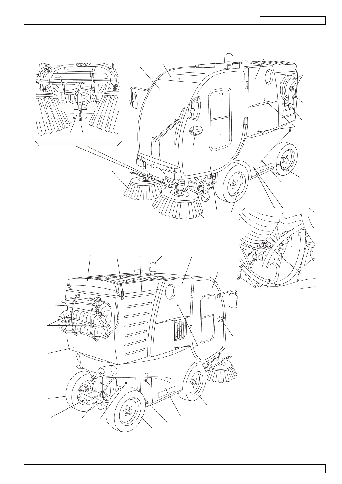
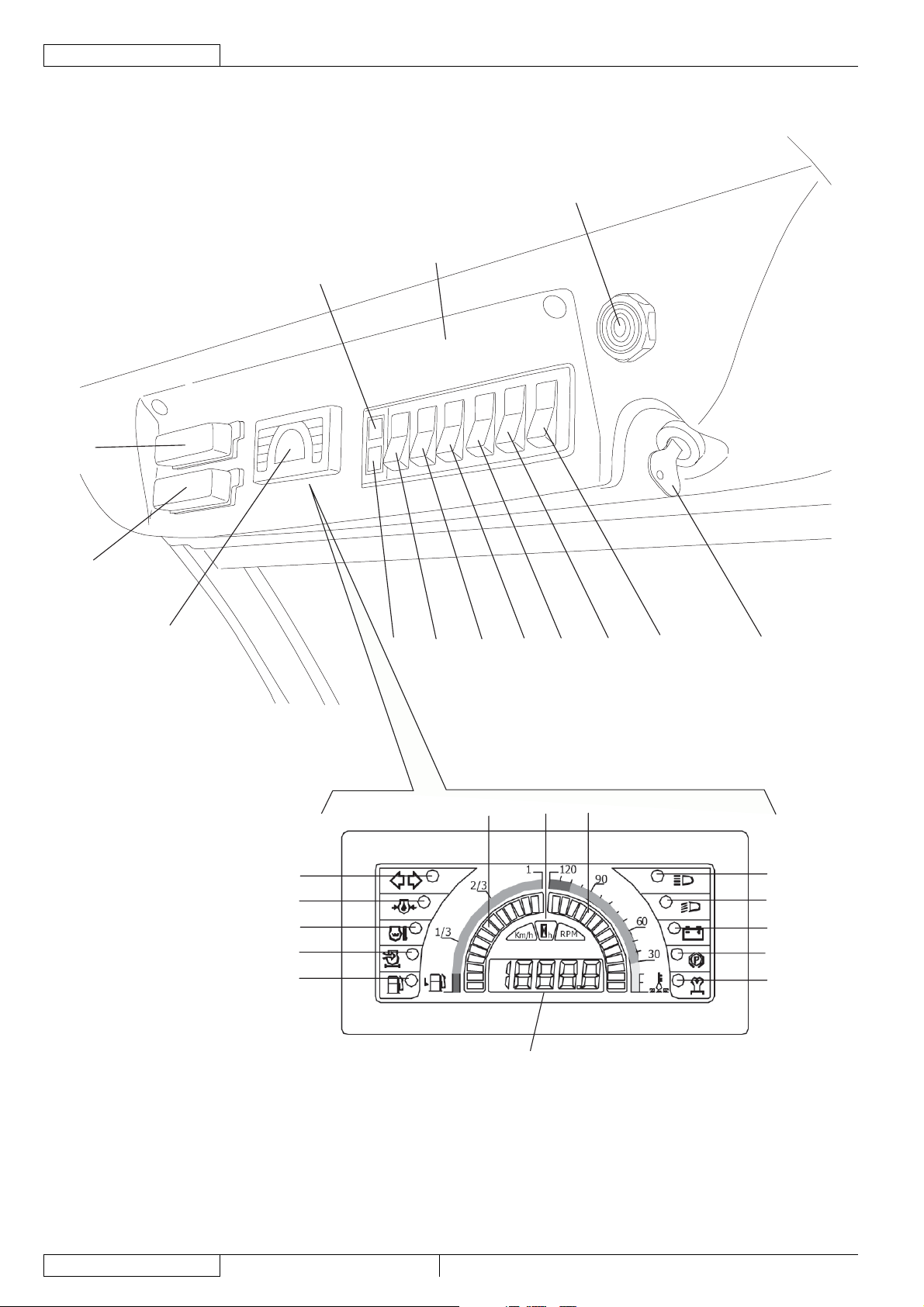
MACHINE NOMENCLATURE
Throughout this Manual you will fi nd numbers in brackets, for example: (2). These numbers refer to the components indicated in
these two nomenclature pages. Refer to these pages whenever it will be necessary to identify a component mentioned in the text.
Cab
1.
Left door
2.
Hopper
3.
Diesel engine
4.
Suction fan
5.
Flashing light
6.
Dust control system left tank
7.
Front fi xed wheels
8.
Rear steering wheels
9.
Right side broom
10.
Left broom
11.
Suction inlet
12.
Right door
13.
Meter and control panel
14.
Rear axle
15.
Dust control system right tank
16.
Rear suction pipe (*)
17.
Left lid
18.
Left lid fasteners
19.
Right lid
20.
Right lid fasteners
21.
Cab right panel
22.
Cab left panel
23.
Right door handle
24.
Left door handle
25.
Hopper lid
26.
Open lid support rod
27.
Lifted hopper locking pins
28.
Lifted hopper locking pins housing
29.
Lifted hopper locking pins holes
30.
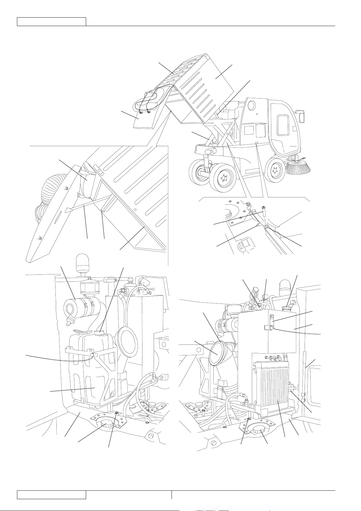
Suction fi lter
31.
Drain fi lter
32.
Hydraulic system oil tank
33.
Battery
34.
Hydraulic system oil cooler
35.
Suction inlet-to-hopper pipe
36.
Fuel tank
37.
Hopper manual lifting hand pump (to be used in case of
38.
engine malfunction)
Hydraulic system oil drain fi lter
39.
Hopper lifting device
40.
Dust control system left tank
41.
Left tank mounting screw
42.
Dust control system right tank
43.
Right tank mounting screw
44.
Front towing hook
45.
Engine air fi lter
46.
Fuel tank fi ller neck
47.
Hopper support rods
48.
Left water tank fi ller plug
49.
Right water tank fi ller plug
50.
Brake fl uid tank
51.
Windscreen wiper fl uid tank
52.
Windscreen wiper motor
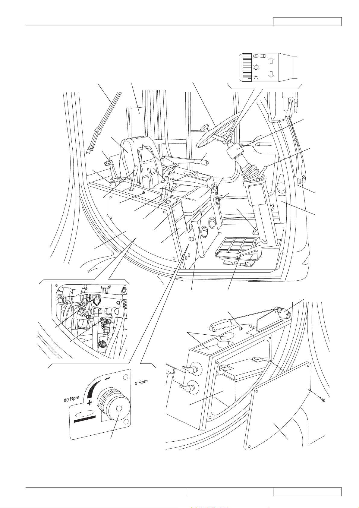
53.
Combination switch
54.
Steering wheel adjusting lever
55.
Drive pedal
56.
Brake pedal
57.
Steering wheel
58.
Driver’s seat
59.
Suction inlet and brooms control lever
60.
61.
Driver’s seat safety belt (*)
62.
Hopper lifting/lowering lever
63.
Suction activation lever
64.
Cab heater control knob
65.
Diesel engine throttle lever
66.
Parking brake lever
67.
Broom dust control system nozzle valve
68.
Suction inlet dust control system nozzle valve
69.
Skirt lifting switch
70.
Lifted hopper warning light (red)
71.
Hazard warning light switch
72.
Dust control system switch
73.
Cab blower switch
74.
Windscreen wiper/washer switch
75.
Climate control system switch (*)
76.
Ignition key
77.
Dust control system water tank warning light (red)
78.
Warning buzzer (it activates together with the warning
lights 87, 91, 93, 94)
79.
Fuse box B
80.
Fuse box A
81.
Indicators and warning lights
82.
Optional indicator light
83.
Optional indicator light
84.
Engine coolant temperature
85.
High beam indicator light
86.
Running light indicator light
87.
Charged battery indicator light (together with the indicator
light a buzzer activates with intermittent sound)
88.
Parking brake indicator light (together with the indicator
light a buzzer activates with continuous sound)
89.
Glow plug pre-heating warning light
90.
Hour counter/revolution counter display:
•
It displays the hours, when the ignition key (76) is
turned on the fi rst position, before running the engine;
•
It displays the engine speed, when the engine is
running and the charged battery warning light is off.
91.
Low fuel warning light (a buzzer activates together with the
warning light)
92.
Optional indicator light
93.
Engine coolant high temperature warning light (a buzzer
activates together with the warning light)
94.
Engine oil pressure warning light (a buzzer activates
together with the warning light)
95.
Turn signal indicator light
96.
Hopper lid opening/closing switch
97.
Rear bumper
Diesel engine serial number/technical data plate (another
98.
plate showing the same data as the plate affi xed on the
diesel engine)(*)
High-pressure washing system hose with reel (*)
99.
High-pressure water quick coupling (*)
100.
Breather fi lter hood fasteners
101.
Rear suction pipe fastener
102.
Front skirt
103.
Machine serial number
104.
Hopper (dumping position)
105.
Suction hose gasket
106.
RS 501 33015500(3)2008-02
11
Page 14

ENGLISH
SERVICE MANUAL
GENERAL INFORMATION
Hopper manual lifting hand pump lever
107.
High-pressure water gun
108.
Serial number plate/technical data/certifi cation marking
109.
Right water tank drain plug
110.
Left water tank drain plug
111.
High-pressure washing system pressure gauge
112.
Breather fi lter hood
113.
Hydraulic system oil fi ller plug
114.
Hydraulic system pressure intake (on drive system pump)
115.
Hydraulic system pressure intake (at suction fan pump)
116.
Hydraulic system pressure intake (at accessory and
117.
steering system pump)
Hopper lid suction sealing gasket
118.
Document holder
119.
Hopper lifting/lowering lever safety fl ange
120.
Suction inlet and broom lifting/lowering lever safety fl ange
121.
Driver’s seat forward/backward adjustment lever
122.
Ashtray
123.
High-pressure water gun sprinkler nozzle
124.
Cigarette lighter
125.
Can holder
126.
Broom speed adjuster (***)
127.
Hydraulic system oil level indicator
128.
(*) Optional for some countries.
12
33015500(3)2008-02 RS 501
Page 15
MACHINE NOMENCLATURE (Continues)
1
14
SERVICE MANUAL
GENERAL INFORMATION
ENGLISH
18
99
104
12
103
45
10
100
112
19
25
111
7
8
2
11
3101113
6
20
13
115
17
102
26
9
97
15
24
21
98
8
4
9
RS 501 33015500(3)2008-02
16
110
S301479
13
Page 16
ENGLISH
SERVICE MANUAL
GENERAL INFORMATION
MACHINE NOMENCLATURE (Continues)
32
26
5
105
48
40
28
37
46
27
31
118
47
36
106
29
38
39
30
114
128
33
107
51
14
41
49
42
33015500(3)2008-02 RS 501
44
50
35
43
S301617
Page 17
MACHINE NOMENCLATURE (Continues)
SERVICE MANUAL
GENERAL INFORMATION
ENGLISH
64
22
108
65
63
59
69
119
121
61
120
60
123
109
58
62
66
68
67
57
54
55
53
52
116
117
127
126
34
122
56
125
124
23
S301481
RS 501 33015500(3)2008-02
15
Page 18
ENGLISH
SERVICE MANUAL
GENERAL INFORMATION
MACHINE NOMENCLATURE (Continues)
70
80
78
1
79
81
95
94
93
92
91
77 71
73 74
82
72
83 84
75
96
76
85
86
87
88
89
16
90
S301407
33015500(3)2008-02 RS 501
Page 19
SERVICE MANUAL
SWEEPING SYSTEM
SWEEPING SYSTEM
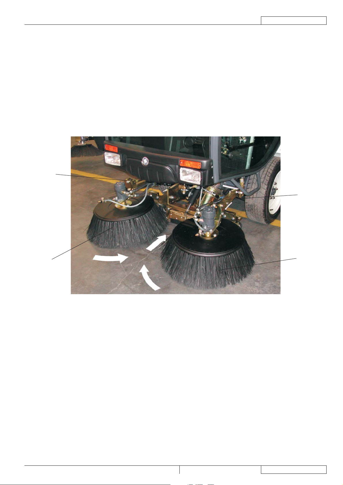
DESCRIPTION
The sweeping system consists of:
A)
Right side broom
B)
Left broom
C)
Broom arms
The brooms (A) and (B) are supported by arms (C) which are fastened to the machine frame.
Broom rotation is activated by hydraulic motors.
For proper sweeping and conveyance of dust and debris towards the suction inlet:
–
Broom height and tilting must be properly adjusted;
–
Proper brooms must be used according to the type of ground to be cleaned. The following types are available:
•
Polypropylene brooms
•
Polypropylene and steel brooms
C
ENGLISH
A
C
B
S300857
RS 501 33015500(3)2008-02
17
Page 20

ENGLISH
SERVICE MANUAL
SWEEPING SYSTEM
TROUBLESHOOTING
The brooms do not clean correctly
Possible causes:
The brooms are not adjusted correctly (adjust).
1.
The broom speed is not correct (adjust).
2.
The brooms do not rotate
Possible causes:
There are oil leaks from the hydraulic system hoses (replace the hoses).
1.
The hydraulic motors are faulty (replace).
2.
The accessory system hydraulic pump does not pressurize the oil in the circuit (check the hydraulic system oil pressure).
3.
18
33015500(3)2008-02 RS 501
Page 21

SERVICE MANUAL
ENGLISH
SWEEPING SYSTEM
SIDE BROOM POSITION CHECK AND ADJUSTMENT
NOTE
Brooms of various hardness are available. This procedure is applicable to all types of brooms.
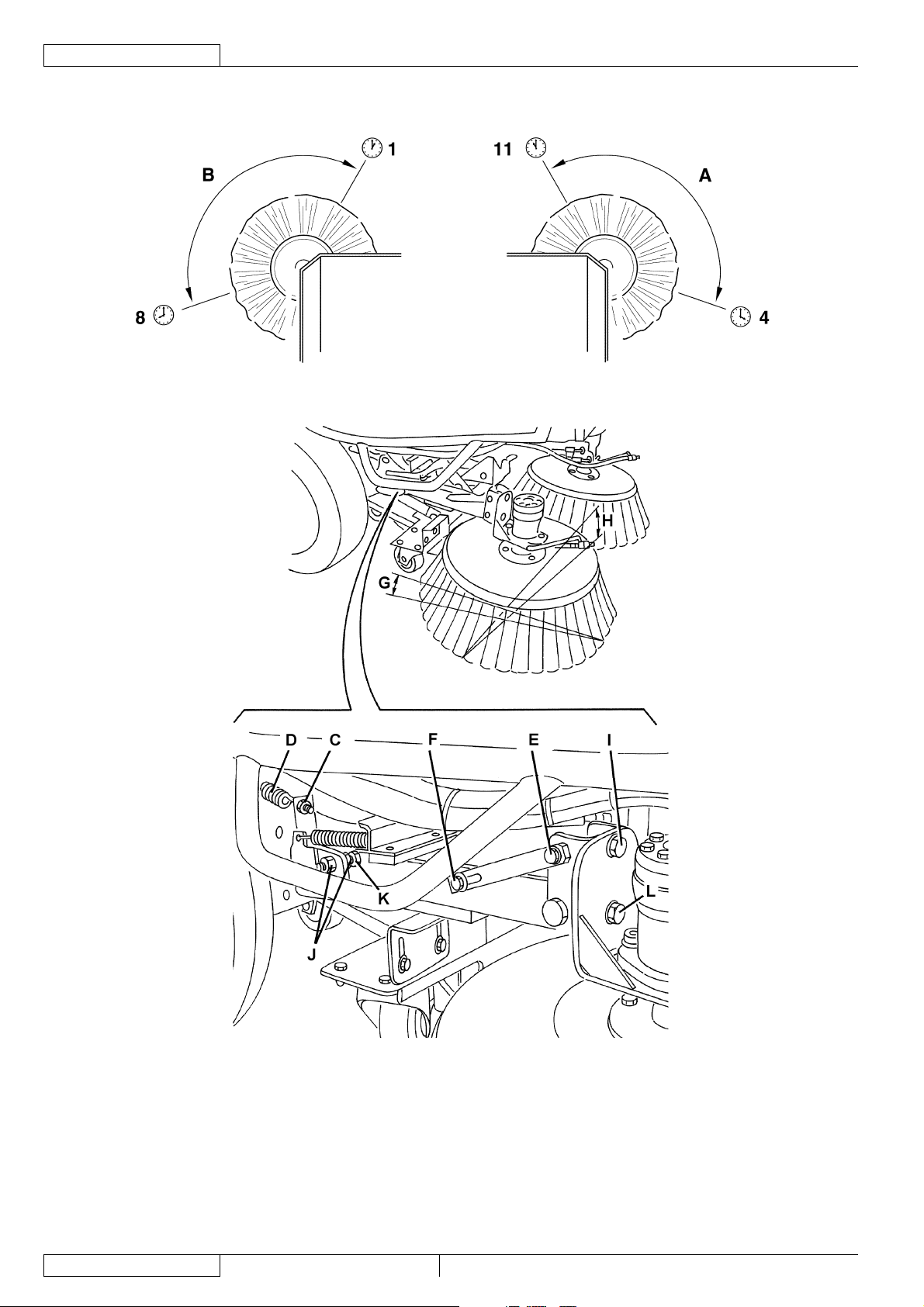
Check
Check the side brooms for proper height and tilting, according to the following procedure:
1.
Drive the machine on a level ground.
•
While keeping the machine stationary, fully lower the side brooms and allow them to rotate for a few seconds.
•
Stop and lift the side brooms, then move the machine.
•
Check that the size and orientation of the prints left by the side brooms are as follows:
•
The right side broom must touch the ground along a circle arc (A) ranging from “11 o’clock” position to “4 o’clock” position.
•
The left side broom must touch the ground along a circle arc (B) ranging from “8 o’clock” position to “1 o’clock” position.
•
Adjust the broom height when the prints are out of specifi cation, according to the following procedure.
Engage the parking brake with the lever (66).
2.
Turn the ignition key (76) to OFF position and remove it.
3.
Broom height adjustment
On both sides of the machine, operate on the tensioning self-locking nut (C) of the spring (D) and consider the following:
4.
To lower the broom, the nut (C) must be unscrewed;
•
To lift the broom, the nut (C) must be screwed.
•
Perform step 1 again.
5.
Broom forward tilting angle adjustment
On both sides of the machine, loosen the screws (E) and (F), then adjust the forward tilting angle (G).
6.
When the adjustment is completed, tighten the screws (E) and (F).
Perform step 1 again.
7.
Broom side tilting angle adjustment
On both sides of the machine, loosen the screws (I) and (L), then adjust the side tilting angle (H).
8.
When the adjustment is completed, tighten the screws (I) and (L).
Perform step 1 again.
9.
Broom side position adjustment
The purpose of this adjustment is to improve the side position of the brooms as to the suction inlet (12).
10.
To perform the adjustment, loosen the nuts (J) and operate on the screw (K), thus changing the side position of the brooms.
11.
When the side brooms are too worn out, the adjustment is not possible; replace the brooms according to the instructions in the
12.
relevant paragraph.
RS 501 33015500(3)2008-02
19
Page 22
ENGLISH
SERVICE MANUAL
SWEEPING SYSTEM
SIDE BROOM POSITION CHECK AND ADJUSTMENT (Continues)
20
S301482
33015500(3)2008-02 RS 501
Page 23
SERVICE MANUAL
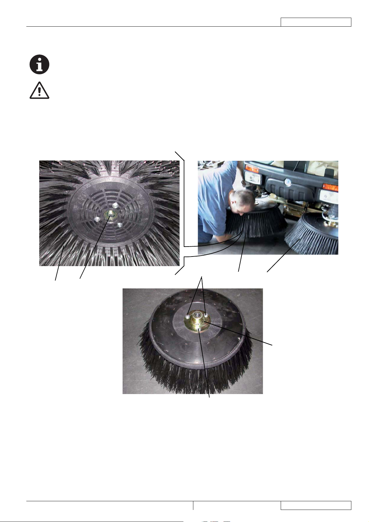
BROOM REPLACEMENT
NOTE
Brooms of various hardness are available. This procedure is applicable to all types of brooms.
CAUTION!
It is advisable to use protective gloves when cleaning the side brooms because there can be sharp debris
between the bristles.
1.
Lift the brooms and engage the parking brake with the lever (66).
2.
Turn the ignition key (76) to OFF position and remove it.
3.
Remove the centre screw (A), then remove the broom (B) to be replaced. Recover the key.
4.
Remove the screws (D), then remove the fl ange (E).
5.
Install the fl ange (E) and secure it on the new broom with the screws (D).
6.
Install the new broom (B) with the key, then tighten the centre screw (A).
7.
Adjust the height of the new broom according to the procedure shown in the previous paragraph.
ENGLISH
SWEEPING SYSTEM
B
A
D
D
B
B
E
S300859
RS 501 33015500(3)2008-02
21
Page 24
ENGLISH
SERVICE MANUAL
SWEEPING SYSTEM
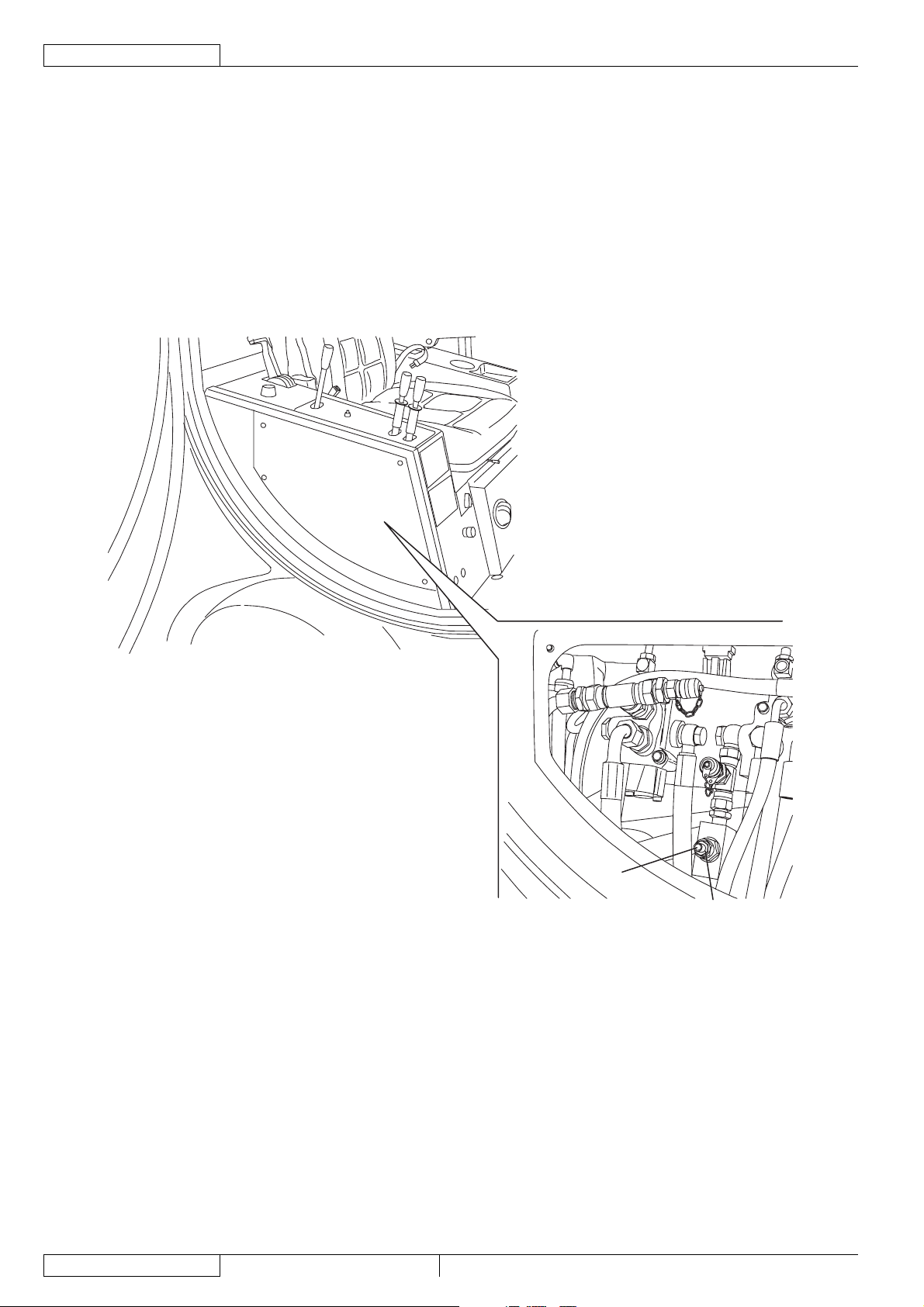
BROOM SPEED ADJUSTMENT
Speed measurement
1.
Engage the parking brake with the lever (66).
2.
Turn the ignition key (76) to OFF position and remove it.
Connect a speed measurement indicator with a portable tachometer to the broom (10) or (11).
3.
4.
Start the machine and run the engine at maximum speed and set the broom speed adjuster (127) to maximum speed (as
shown in the User Manual). In this condition, measure the broom speed with the portable tachometer. Turn off the machine.
The broom speed must be: 80 rpm
If necessary, change the broom speed according to the following procedure.
Speed adjustment
5.
Remove the screws and the right panel (22) in the cab.
6.
To change the broom speed, loosen the locknut (A) and turn the screw (B), then tighten the locknut (A).
7.
Perform step 4 again.
22
B
A
S301510
33015500(3)2008-02 RS 501
Page 25

SERVICE MANUAL
ENGLISH
DUST AND DEBRIS COLLECTION SYSTEM
DUST AND DEBRIS COLLECTION SYSTEM
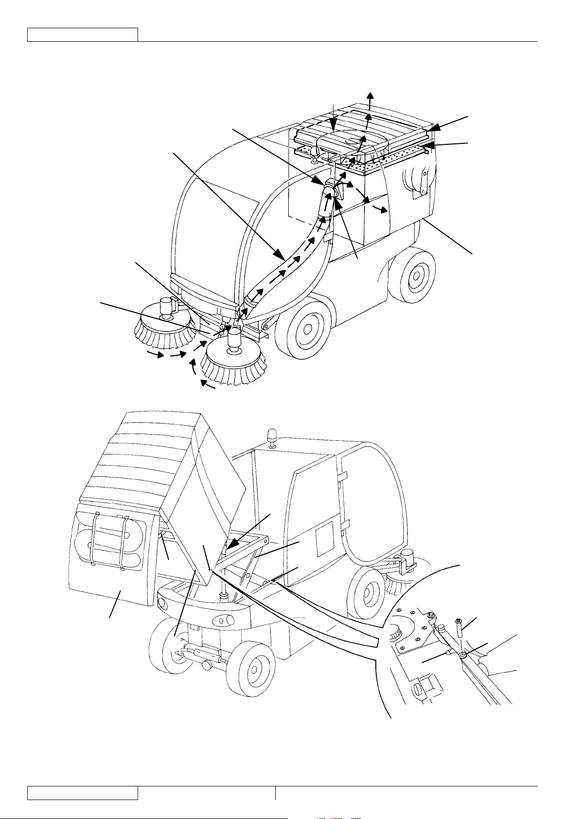
DESCRIPTION
The dust and debris collection system consists of:
Suction fan
A)
Dust and debris suction fi lter
B)
Hopper
C)
Suction hose
D)
Suction inlet
E)
Skirt
F)
Gasket between suction inlet and hopper
G)
Hopper lid
H)
Hopper suction hole
I)
Open lid support rod
J)
Lifted hopper locking pins
K)
Lifted hopper locking pins housing
L)
Lifted hopper locking pins holes
M)
Air breather fi lter
N)
Hopper lid suction sealing gasket
Q)
The suction fan (A), activated by an hydraulic motor, creates vacuum inside the hopper (C). The vacuum determines the suction
capacity of the suction inlet (E) through the suction hose (D).
The hopper (C) is made of steel.
It is fastened with two pins to a mechanic/hydraulic lifting system (O) (for hopper lifting) and to a dumping system (P) (for hopper
tilting). The lid (H), which can be opened with an hydraulic control system, allows for debris discharging.
Both the lid (H) and the suction hole (I) are equipped with gaskets, which allow the suction inlet (E) to reach the maximum suction
capacity.
Inside the hopper there are two stainless steel fi lters having the following functions:
The suction fi lter (B) retains dust and debris during fan suction phase, and makes them settle in the hopper;
–
The breather fi lter (N) retains dust and debris escaped from the suction fi lter, and does not allow them to be discharged
–
externally.
Both fi lters can be easily removed and cleaned.
To perform checks and maintenance procedure safely with the hopper lifted and the lid opened, perform the following procedures:
Turn the rod (J) to lock the lid (H) in open position.
–
Remove the pins (K) from the housings (L) and place them into the holes (M) to lock the hopper (C) in lifted and dumped
–
position.
The suction inlet is made of sheet steel.
It is equipped with three wheels, which allow it to follow the pattern of the surface to be cleaned.
On its front side there is a skirt (F) that must be lifted to collect bulky debris.
RS 501 33015500(3)2008-02
23
Page 26
ENGLISH
SERVICE MANUAL
DUST AND DEBRIS COLLECTION SYSTEM
DESCRIPTION (Continues)
G
A
N
D
E
B
C
I
F
H
P
K
J
O
K
K
Q
M
L
S301483
24
33015500(3)2008-02 RS 501
Page 27

SERVICE MANUAL
DUST AND DEBRIS COLLECTION SYSTEM
TROUBLESHOOTING
The suction fan turns but it is not effi cient
Possible causes:
The fi lters are clogged (clean).
1.
The suction hose is clogged (clean).
2.
The suction hose is cut/torn (replace).
3.
The gasket between the suction inlet and the hopper is broken or misadjusted (replace or adjust).
4.
The hopper lid gasket is broken (replace).
5.
There is no pressure at the suction fan motor drive pump (adjust the pump pressure).
6.
The suction fan does not turn
Possible causes:
The motor is faulty (replace).
1.
The control valve assembly is stuck (repair).
2.
The pump is faulty (replace).
3.
The suction inlet does not collect debris effi ciently
Possible causes:
The suction inlet position is incorrect (check the suction inlet and skirt height and effi ciency).
1.
The skirt opening force is not suffi cient
Possible causes:
The skirt opening pressure is incorrect (adjust).
1.
The hopper does not lift/lower
Possible causes:
The control valve assembly is stuck (repair).
1.
The cylinder gaskets are worn (repair the cylinder).
2.
The rear lid does not open/close
Possible causes:
There is no voltage in the actuator (repair the electrical system).
1.
The actuator is faulty (repair/adjust the actuator cams).
2.
ENGLISH
RS 501 33015500(3)2008-02
25
Page 28

ENGLISH
SERVICE MANUAL
DUST AND DEBRIS COLLECTION SYSTEM
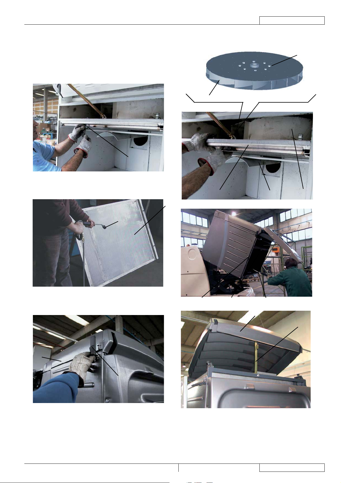
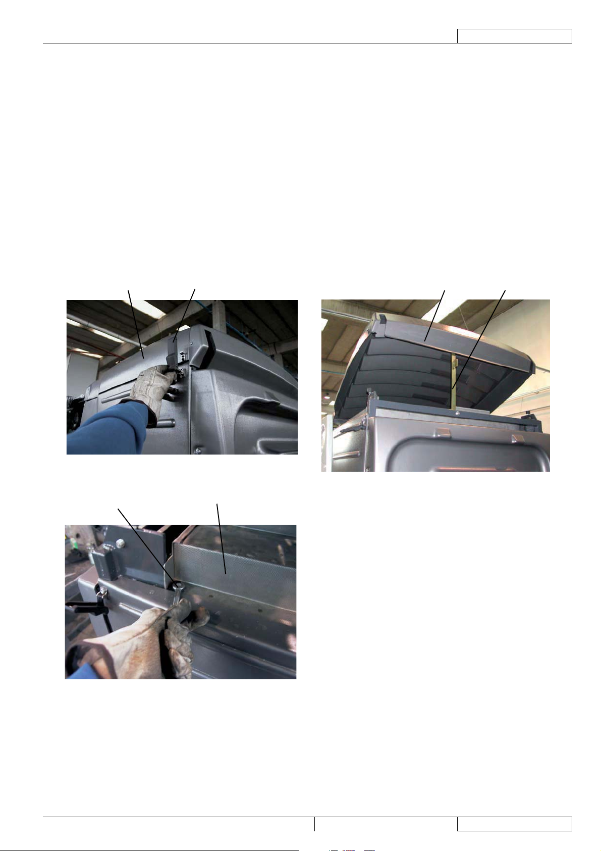
HOPPER, FILTER AND SUCTION HOSE CLEANING, AND GASKET CHECK
WARNING!
Protect body parts (eyes, hair, hands, etc.) properly, when performing cleaning procedures using compressed
air or water gun.
Preliminary operations
Empty the hopper (3), drive the machine to a cleaning/washing appointed area, then engage the parking brake with the lever
1.
(66).
Lift and dump the hopper (3), according to the procedure shown in the User Manual.
2.
Install the lid support rod (27).
3.
Hopper cleaning
Clean the hopper (H) with pressurised water from a hydrocleaner (G).
4.
Carefully check the suction sealing gasket (U) for integrity, and replace it if necessary.
5.
Suction hose cleaning
Thoroughly clean the suction hose (R) inside, up to the suction inlet, with pressurised water.
6.
Carefully check the suction sealing gasket (V) for integrity, and replace it if necessary.
7.
Suction fi lter cleaning
Inside the hopper, remove the suction fi lter fastener (A).
8.
Remove the suction fi lter (B).
9.
Wash the defl ector (C) and the fan (D) with pressurised water; check that all fan sectors (T) are clean.
10.
Clean the suction fi lter (F) with pressurised water from a hydrocleaner (E).
11.
Install the suction fi lter (B) and secure it with the fastener (A).
12.
Remove the lid support rod (27) and lower the hopper (3) according to the procedure shown in the User Manual.
13.
Turn the ignition key (76) to OFF position and remove it.
14.
Breather fi lter cleaning
With a ladder and the help of an assistant, disengage the fasteners (I) of the breather fi lter hood (J).
15.
Open the hood (K) and install the safety pin (L).
16.
Remove the mounting screws (M), then remove the breather fi lter (N).
17.
Clean the breather fi lter (P) with pressurised water from a hydrocleaner (O).
18.
Install the breather fi lter and its hood performing steps from 15 to 17 in reverse order.
19.
26
33015500(3)2008-02 RS 501
Page 29
SERVICE MANUAL
DUST AND DEBRIS COLLECTION SYSTEM
HOPPER, FILTER AND SUCTION HOSE CLEANING, AND GASKET CHECK (Continues)
T
A
ENGLISH
D
DCB
F
E
U
H
G
K
L
J
I
S300862
RS 501 33015500(3)2008-02
27
Page 30
ENGLISH
SERVICE MANUAL
DUST AND DEBRIS COLLECTION SYSTEM
HOPPER, FILTER AND SUCTION HOSE CLEANING, AND GASKET CHECK (Continues)
NMPO
V
R
S300863
28
33015500(3)2008-02 RS 501
Page 31

SERVICE MANUAL
ENGLISH
DUST AND DEBRIS COLLECTION SYSTEM
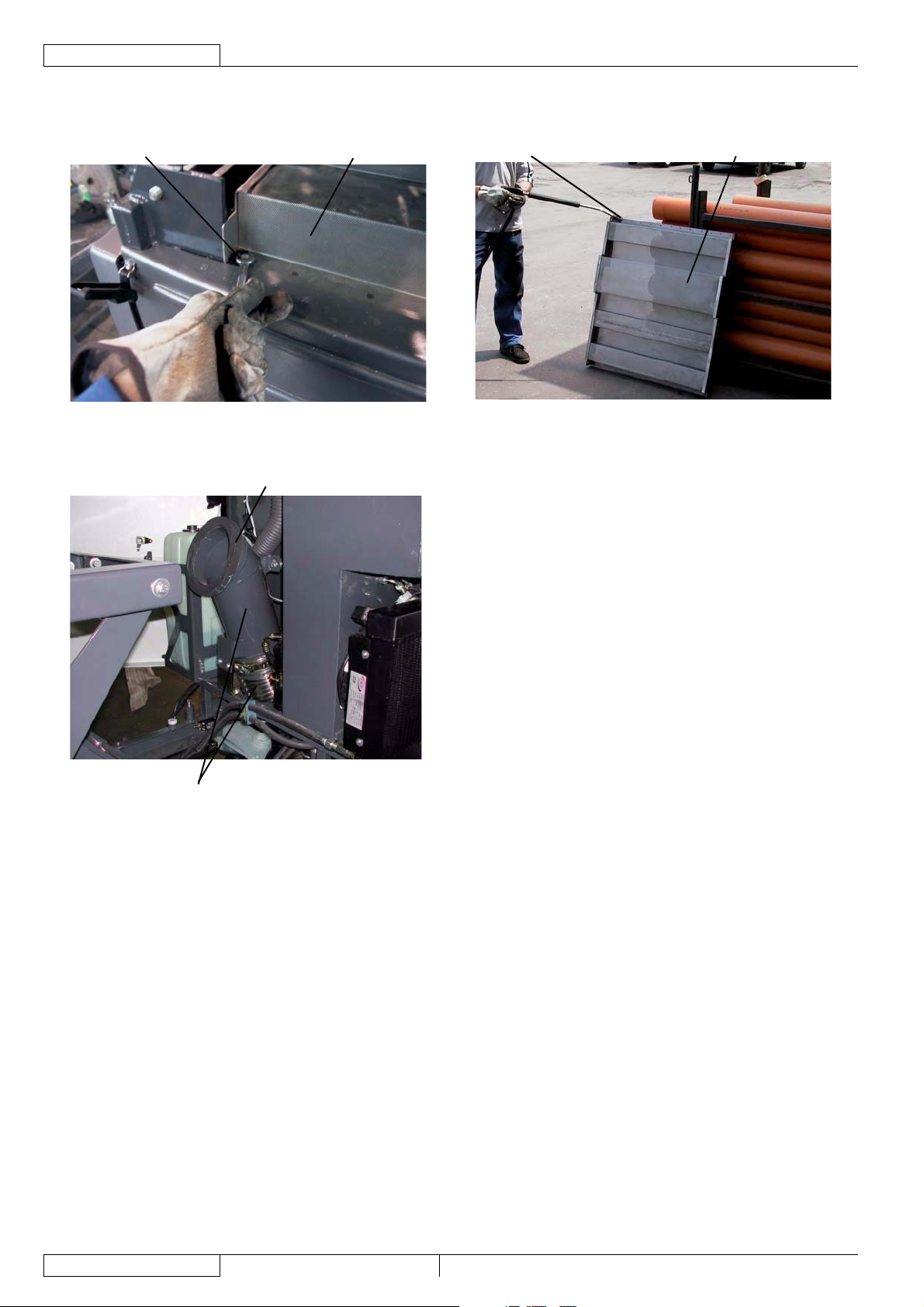
SUCTION INLET AND SKIRT HEIGHT AND OPERATION CHECK
Preliminary operations
Engage the parking brake with the lever (66).
1.
Lift the suction inlet (12), according to the procedure shown in the User Manual.
2.
Turn the ignition key (76) to OFF position and remove it.
3.
Suction inlet wheel check
Check that the three wheels (A) of the suction inlet are in good conditions and turn freely (they must not be bent/misshapen
4.
because of bumps or excessive pressure, etc.). Check also that the rubber thickness (B) is not lower than some millimeters.
If necessary replace the wheels (A) (see the procedure in relevant paragraph).
Sliding panel check
Check that the main sliding panel (C) and the front (D) and (E) and rear (H) sliding panels are in good conditions and that their
5.
thickness (F) is not lower than 5 mm, otherwise replace them (see the procedure in the relevant paragraph).
It is important to replace the sliding panels (C), (D), (E), and (H) when they are not completely worn, to avoid damaging the
relevant mounting screws and making them diffi cult to remove.
Replace the sliding panels (C), (D), (E), and (H) as a unit, to avoid steps in the union areas (G), caused by different levels of
wear.
Suction inlet skirt and wheel adjustment check
Check that the skirt (I) is integral and that it does not have excessive tears (J) or lacerations (K), which can affect the suction
6.
inlet operation.
If necessary replace the skirt (I) (see the procedure in the relevant paragraph).
Drive the machine on a level ground and lower the suction inlet (12) according to the procedure shown in the User manual.
7.
Turn the ignition key (76) to OFF position and remove it.
8.
Check that the distance (L) of the skirt from the ground is not bigger than 1 cm. Greater distances can affect the suction inlet
9.
operation.
If necessary replace the skirt (K) (see the procedure in the relevant paragraph).
Also check that, when the three wheels (A) contact the ground, the sliding panels (C), (D), (E), and (H) do not touch the
10.
ground, otherwise the wheels (A) must be replaced to avoid an excessive wear of the sliding panels (for wheel replacement
procedure, see the relevant paragraph).
Start the machine according to the procedure shown in the User Manual, then press the switch (69) and check that the skirt
11.
(I) lifts freely. Check that it lifts also when a force of some kg is applied (simulating to move bottles or other heavy objects that
must then be collected). If necessary, adjust the opening force of the skirt (I) according to the following procedure:
Turn off the machine.
•
Remove the screws and the right panel (22) in the cab.
•
Loosen the control valve locknut (N) and turn the screw (O) as necessary, reminding that:
•
The opening force decreases by loosening the screw;
–
The opening force increases by tightening the screw.
–
When the adjustment is completed, tighten the locknut (N).
•
Install the right panel (22) in the cab and tighten the screws.
•
Reset
Assemble the components in the reverse order of disassembly.
12.
RS 501 33015500(3)2008-02
29
Page 32

ENGLISH
SERVICE MANUAL
DUST AND DEBRIS COLLECTION SYSTEM
SUCTION INLET AND SKIRT HEIGHT AND OPERATION CHECK (Continues)
E
A
D
C
G
H
A
G
B
F
F
G
L
J
A
IK
N
O
S301484
30
33015500(3)2008-02 RS 501
Page 33

SERVICE MANUAL
ENGLISH
DUST AND DEBRIS COLLECTION SYSTEM
SUCTION INLET WHEEL DISASSEMBLY/ASSEMBLY
NOTE
To remove the rear wheel (C), the machine must be lifted with an appropriate hoisting system. Otherwise, remove the
suction inlet assembly (D) according to the procedure shown in the relevant paragraph. See the following disassembling
procedures.
Front wheels (A) and (B) removal/installation
Engage the parking brake with the lever (66).
1.
Lift the suction inlet (12), according to the procedure shown in the User Manual.
2.
3.
Turn the ignition key (76) to OFF position and remove it.
4.
On both sides of the machine, loosen the screws (E) and (F), then remove the front wheels (A) and (B).
5.
Install the new front wheels (A) and (B) and fasten them with the screws (E) and (F).
If necessary, perform the suction inlet and skirt height and operation check (see the procedure in the relevant paragraph).
6.
Front wheels (A) and (B), and rear wheel (C) removal/installation
7.
Place the machine on the appropriate hoisting system (if present) and lift it.
If the hoisting system is not available, remove the suction inlet assembly (D) (see the procedure in the relevant paragraph).
8.
Remove the screws (E), (F) and (G), then remove the wheels (A), (B) and (C).
9.
Install the new wheels (A), (B) and (C) and fasten them with the screws (E), (F) and (G).
10.
Perform step 1 again.
11.
If necessary, perform the suction inlet and skirt height and operation check (see the procedure in the relevant paragraph).
A
E
B
D
C
G
F
S301485
RS 501 33015500(3)2008-02
31
Page 34

ENGLISH
SERVICE MANUAL
DUST AND DEBRIS COLLECTION SYSTEM
SUCTION INLET SLIDING PANELS DISASSEMBLY/ASSEMBLY
NOTE
To remove the suction inlet sliding panels, the machine must be lifted with an appropriate hoisting system. Otherwise,
remove the suction inlet assembly (D) according to the procedure shown in the relevant paragraph. See the following
disassembling procedures.
Place the machine on the appropriate hoisting system (if present) and lift it.
1.
If the hoisting system is not available, remove the suction inlet assembly (D) (see the procedure in the relevant paragraph).
2.
Remove the mounting screws (A), and (B), then remove the sliding panels (C), (D), and (E).
3.
Install the new sliding panels (C), (D), and (E) and fasten them with the screws (A), and (B).
4.
Also check that, when the wheels (F) contact the ground, the sliding panels (C), (D), and (E) do not touch the ground,
otherwise the wheels (F) must be replaced to avoid an excessive wear of the sliding panels (for wheel replacement procedure,
see the relevant paragraph).
5.
Perform step 1 again.
6.
If necessary, perform the suction inlet and skirt height and operation check (see the procedure in the relevant paragraph).
C
A
F
E
BF
D
C
A
F
S301486
32
33015500(3)2008-02 RS 501
Page 35

SERVICE MANUAL
ENGLISH
DUST AND DEBRIS COLLECTION SYSTEM
SUCTION INLET DISASSEMBLY/ASSEMBLY
Disassembly
1.
Remove the side brooms (see the procedure in the relevant paragraph).
Lower the suction inlet (12), according to the procedure shown in the User Manual.
2.
Engage the parking brake with the lever (66).
3.
Turn the ignition key (76) to OFF position and remove it.
4.
Disconnect the hydraulic system hoses (A) and (B) from the suction inlet (C) and plug them.
5.
Disconnect the dust control system water hose (D).
6.
Remove the nuts (E) and pins (F).
7.
Move the suction inlet (C) forward, and loosen the suction hose clamp (G).
8.
Disconnect the suction hose (H) from the suction inlet.
9.
Remove the suction inlet (C).
10.
Assembly
Assemble the components in the reverse order of disassembly.
11.
If necessary, perform the suction inlet and skirt height and operation check (see the procedure in the relevant paragraph).
F
B
H
A
G
D
E
E
F
C
S301487
RS 501 33015500(3)2008-02
33
Page 36

ENGLISH
SERVICE MANUAL
DUST AND DEBRIS COLLECTION SYSTEM
SKIRT REPLACEMENT
Lower the suction inlet (12), according to the procedure shown in the User Manual.
1.
2.
Engage the parking brake with the lever (66).
3.
Turn the ignition key (76) to OFF position and remove it.
4.
Remove the clip (A) and the skirt (B).
5.
Remove the screws (C), then remove the skirt (D).
6.
Install the new skirt (D) and fasten it with the screws (C).
7.
Install the skirt (B) and the clip (A).
8.
Lift the suction inlet (12), according to the procedure shown in the User Manual.
A
B
D
C
S300868
34
33015500(3)2008-02 RS 501
Page 37

SERVICE MANUAL
ENGLISH
DUST AND DEBRIS COLLECTION SYSTEM
HOPPER POSITION ADJUSTMENT
Empty the hopper (3); if it contains a small quantity of waste, it is not necessary to dump it.
1.
Drive the machine on a solid and level ground, then engage the parking brake with the lever (66).
2.
Open the right and left lids (20) and (18) by releasing the fasteners (21) and (19) with the supplied key.
3.
Lift the hopper (3), according to the procedure shown in the User Manual.
4.
Turn the ignition key (76) to OFF position and remove it.
5.
Remove the locking pins (28) from the housings (29) and place them into the holes (30).
6.
Loosen the locknuts (A).
7.
Insert a lever into the holes (C), then turn the rods (B) as necessary.
8.
Remove the locking pins (28) and place them into the holes (29).
9.
Lower the hopper (3), according to the procedure shown in the User Manual, and check that the profi les (D) match the frame
10.
profi les (E).
If necessary, perform steps 4, 5, 6, 8, 9 and 10 again.
11.
Then perform steps 3, 4, 5 and tighten the locknuts (A).
12.
Lower the hopper (3), according to the procedure shown in the User Manual, and check that the hopper suction hole (F) match
13.
the suction hose gasket (G). If necessary, adjust the position of the suction hose (H) according to the procedure shown in the
following steps.
Perform steps 4, 5 and 6 again.
14.
Loosen the left and right side screws (I) (J) and (L), then adjust the position of the suction hose (H). Tighten the left and right
15.
side screws (I) (J) and (L).
Lower the hopper (3), according to the procedure shown in the User Manual, and check that the hopper suction hole (F) match
16.
the suction hose gasket (G).
Close the right and left lids (20) and (18) by engaging the fasteners (21) and (19) with the supplied key.
17.
RS 501 33015500(3)2008-02
35
Page 38

ENGLISH
SERVICE MANUAL
DUST AND DEBRIS COLLECTION SYSTEM
HOPPER POSITION ADJUSTMENT (Continues)
D
A
D
B
A
C
B
C
E
E
F
G
I
H
J
L
S300869
36
33015500(3)2008-02 RS 501
Page 39

SERVICE MANUAL
ENGLISH
DUST AND DEBRIS COLLECTION SYSTEM
HOPPER LID CLOSING ACTUATOR ADJUSTMENT
Preliminary operations
1.
Empty the hopper (3), according to the procedure shown in the User Manual.
Drive the machine on a solid and level ground, then engage the parking brake with the lever (66).
2.
Lift the hopper (3), according to the procedure shown in the User Manual.
3.
Turn the ignition key (76) to OFF position and remove it.
4.
Open the right lid (20) by releasing the fasteners (21) with the supplied key.
5.
Remove the locking pins (28) from the housings (29) and place them into the holes (30).
6.
Remove the screws (A), then remove the cover (B) and the gasket (C) of the actuator (R), under the rear side of the hopper.
7.
Lid safety hook closing
According to the procedure shown in the User Manual, turn the safety hook (D) of the lid (E) to closing position (as shown
8.
in the fi gure); in this condition, loosen the security dowel (F) of the cam (G), and then turn the cam until the microswitch (H)
activates.
Open safety hook warning light adjustment
When the safety hook (D) of the lid (E) is turned to closing position (as shown in the fi gure), loosen the security dowel (I) of the
9.
cam (J), and turn the cam until the corner (K) causes the microswitch (L) to activate and the warning light to turn off.
Lid safety hook opening end-of-stroke adjustment
According to the procedure shown in the User Manual, turn the safety hook (D) of the lid (E) to the opening end-of-stroke; in
10.
this condition, loosen the security dowel of the cam (N), and then turn the cam until the microswitch (O) activates.
NOTE
To maximize cam adjustment consider the following:
The cam turns in the direction shown by the arrow (P) when the hook (D) opens;
–
The cam turns in the direction shown by the arrow (Q) when the hook (D) closes.
–
To check the cam proper adjustment, open and close the hook (D) several times.
11.
Reset
12.
Perform steps 3 to 7 in the reverse order.
B
CR
A
S300964
RS 501 33015500(3)2008-02
37
Page 40

ENGLISH
SERVICE MANUAL
DUST AND DEBRIS COLLECTION SYSTEM
HOPPER LID CLOSING ACTUATOR ADJUSTMENT (Continues)
P
G
Q
F
I
NH
L
O
D
E
J
38
K
S300965
33015500(3)2008-02 RS 501
Page 41
SERVICE MANUAL
ENGLISH
DUST AND DEBRIS COLLECTION SYSTEM
MOTOR AND SUCTION FAN DISASSEMBLY/ASSEMBLY
Disassembly
1.
Engage the parking brake with the lever (66).
Turn the ignition key (76) to OFF position and remove it.
2.
With a ladder and the help of an assistant, disengage the fasteners (A) of the breather fi lter hood (B).
3.
Open the hood (C) and install the safety pin (D).
4.
Remove the mounting screws (E), then remove the breather fi lter (F).
5.
Disconnect the hoses joints (G) and (H) from the suction fan motor (I).
6.
Remove the mounting nuts (J) of the fl ange (M).
7.
With an appropriate hoisting system, remove the suction fan motor assembly (K) by removing the silicone along the perimeter
8.
(L) of the fl ange (M), then sling the assembly (K) by placing a rope around the motor (I) and the fi ttings (N).
At the workbench, remove the screw (O) and the fan (P).
9.
Remove the nuts (Q) from the screws (R).
10.
Remove the motor (I) from the fl ange (M).
11.
Assembly
12.
Assemble the components in the reverse order of disassembly and note the following:
•
Remove the silicone along the perimeter (L) of the fl ange (M) and from the fl ange housing on the hopper.
•
Apply new silicone along the perimeter (L) of the fl ange (M).
B
A
CD
E
F
S300870
RS 501 33015500(3)2008-02
39
Page 42

ENGLISH
SERVICE MANUAL
DUST AND DEBRIS COLLECTION SYSTEM
MOTOR AND SUCTION FAN DISASSEMBLY/ASSEMBLY (Continues)
Q
N
H
N
G
J
M
P
K
L
R
O
40
S301488
33015500(3)2008-02 RS 501
Page 43

SERVICE MANUAL
DUST AND DEBRIS COLLECTION SYSTEM
SUCTION HOSE DISASSEMBLY/ASSEMBLY
Preliminary operations
1.
Empty the hopper (3); if it contains a small quantity of waste, it is not necessary to dump it.
Drive the machine on a solid and level ground, then engage the parking brake with the lever (66).
2.
Lift the hopper (3), according to the procedure shown in the User Manual.
3.
Turn the ignition key (76) to OFF position and remove it.
4.
Open the right and left lids (20) and (18) by releasing the fasteners (21) and (19) with the supplied key.
5.
Remove the locking pins (28) from the housings (29) and place them into the holes (30).
6.
Disassembly
Loosen the clamp (A) and disconnect the suction hose (B) from the suction inlet (C).
7.
Loosen the left and right side mounting screws (D) of the suction hose upper end (E).
8.
Remove the suction hose (F) by pulling it upwards.
9.
Assembly
Assemble the components in the reverse order of disassembly and note the following:
10.
For a easier installation of the suction hose (B) into the suction inlet (C), apply a thin coat of grease on the sliding parts.
•
ENGLISH
B
D
F
E
D
D
A
C
S300874
RS 501 33015500(3)2008-02
41
Page 44

ENGLISH
SERVICE MANUAL
DUST AND DEBRIS COLLECTION SYSTEM
42
33016312(0)2007-04 RS 501 UK
Page 45

DUST CONTROL SYSTEM
DESCRIPTION
The dust control system consists of:
A)
Right water tank
B)
Left water tank
Tank fi ller plugs
C)
Broom nozzles
D)
Suction inlet nozzles
E)
Water fi lter
F)
Hose
G)
Water level indicator
H)
Nozzle pump
I)
Taps
J)
Rear suction pipe nozzle
K)
Opening tap
L)
Tank drain plugs
M)
The water gun connected to the dust control system consists of:
Water gun pump
N)
Quick coupling
O)
Water gun
P)
Hose
Q)
Reel
R)
Pressure gauge
S)
QR
SERVICE MANUAL
DUST CONTROL SYSTEM
ENGLISH
D
D
K
G
A
I
J
E
E
C
M
S
P
O
B
B
I
J
F
J
J
N
E
O
C
L
P
K
DD
A
H
N
F
M
RS 501 33015500(3)2008-02
S301489
43
Page 46

ENGLISH
SERVICE MANUAL
DUST CONTROL SYSTEM
TROUBLESHOOTING
No water from the nozzles
Possible causes:
The water fi lter is clogged (clean/replace).
1.
The nozzles are clogged (clean).
2.
No water to the nozzles
Possible causes:
The water pump relay is burned (replace).
1.
The pump does not work (repair/replace).
2.
44
33015500(3)2008-02 RS 501
Page 47

SERVICE MANUAL
ENGLISH
DUST CONTROL SYSTEM
NOZZLE AND FILTER CLEANING
WARNING!
Protect body parts (eyes, hair, hands, etc.) properly, when performing cleaning procedures using compressed
air or water gun.
Preliminary operations
Engage the parking brake with the lever (66).
1.
Turn the ignition key (76) to OFF position and remove it.
2.
Cleaning of nozzles and fi lters on brooms
Unscrew the ring nuts (A).
3.
Clean the nozzles (B) and fi lters (C) with compressed air. Remove calcium deposits. If necessary, replace the fi lters (C).
4.
Install the fi lters and nozzles, and secure them with the ring nuts. Nozzle holes must be directed down when tightening.
5.
Cleaning of nozzles inside the suction inlet
On both sides of the suction inlet (D), remove the screws (E) together with the nozzles (F).
6.
Clean the nozzles (F) and screws (E) with compressed air. Remove calcium deposits.
7.
Assemble the components in the reverse order of disassembly.
8.
Cleaning of nozzle and fi lter in the rear suction pipe
Remove the screw (G), the nozzle (H) and the fi lter (I).
9.
Clean the nozzle (H) and fi lter (I) with compressed air. Remove calcium deposits. If necessary, replace the fi lter (I).
10.
Assemble the components in the reverse order of disassembly.
11.
RS 501 33015500(3)2008-02
45
Page 48

ENGLISH
SERVICE MANUAL
DUST CONTROL SYSTEM
NOZZLE AND FILTER CLEANING (Continues)
C
E
A
B
A
E
D
F
F
46
H
I
G
S301490
33015500(3)2008-02 RS 501
Page 49

SERVICE MANUAL
DUST CONTROL SYSTEM
WATER FILTER CLEANING
WARNING!
Protect body parts (eyes, hair, hands, etc.) properly, when performing cleaning procedures using compressed
air or water gun.
NOTE
When the fi lter is removed, the water inside the tanks comes out up to the fi lter level.
Preliminary operations
1.
Turn the ignition key (76) to OFF position and remove it.
2.
Engage the parking brake with the lever (66).
3.
In the area over the rear axle (15), remove the water fi lter cover (A) together with the fi lter (B).
Separate the fi lter (B) from the cover (A), then wash and clean it. If necessary, replace the fi lter (B).
4.
Install the fi lter (B) and the cover (A).
5.
6.
If necessary, fi ll the water tanks.
ENGLISH
B
A
A
S301491
RS 501 33015500(3)2008-02
47
Page 50

ENGLISH
SERVICE MANUAL
DUST CONTROL SYSTEM
WATER TANK EMPTYING
When necessary, empty the dust control system water tanks (7 and 16) according to the following procedure.
1.
Turn the ignition key (76) to OFF position and remove it.
2.
Engage the parking brake with the lever (66).
Remove the water tank drain plugs (A) and (B) and drain all the water from the tanks.
3.
4.
Install the plugs (A) and (B).
A
B
S301492
48
33015500(3)2008-02 RS 501
Page 51

SERVICE MANUAL
ENGLISH
STEERING SYSTEM
STEERING SYSTEM
DESCRIPTION
The steering wheel activates the steering gearbox, which controls an hydraulic cylinder that operates on the rear wheels assembled
on a steering axle.
The steering system consists of:
A)
Oil pump
B)
Priority valve
C)
Steering gearbox
D)
Rear wheel control hydraulic cylinder
E)
Hydraulic system oil tank
F)
Hydraulic system hoses
E
D
C
B
A
F
S300878
RS 501 33015500(3)2008-02
49
Page 52

ENGLISH
SERVICE MANUAL
STEERING SYSTEM
TROUBLESHOOTING
The machine does not move straightforward
Possible causes:
The rear axle toe-in is incorrect (adjust).
1.
The steering is hard
Possible causes:
The steering gearbox is faulty (replace).
1.
The priority valve is faulty (replace).
2.
The rear wheel control hydraulic cylinder is faulty (replace).
3.
50
33015500(3)2008-02 RS 501
Page 53

SERVICE MANUAL
ENGLISH
STEERING SYSTEM
REAR AXLE TOE-IN ADJUSTMENT
Drive the machine on a solid and level ground and keep the rear wheels (A) in a straightforward position, then engage the
1.
parking brake with the lever (66).
2.
Turn the ignition key (76) to OFF position and remove it.
Prepare two metal plates (B) to be used as reference lines. The plates must be a little longer than the wheel diameter.
3.
4.
Place the plates (B) on the external surface of the wheels (A), at the centre of the wheels and parallel to the ground, as shown
in the fi gure.
Do not place the plates (B) where the tire surface is irregular.
5.
Keeping the plates (B) in the above-mentioned position, check that the distances (E) and (F), measured on the front and on
the back of the wheels (A), are the same. A maximum difference of 4 mm between the two distances is admitted. If necessary,
adjust the distances by loosening the nuts (D) and turning the tie rods (C). Then tighten the nuts (D).
B
B
A
E
A
B
F
A
A
RS 501 33015500(3)2008-02
B
S300879
51
Page 54

ENGLISH
SERVICE MANUAL
STEERING SYSTEM
REAR AXLE TOE-IN ADJUSTMENT (Continues)
D
C
C
D
S300880
52
33015500(3)2008-02 RS 501
Page 55

SERVICE MANUAL
ENGLISH
BRAKE SYSTEM
BRAKE SYSTEM
DESCRIPTION
The machine is equipped with an hydraulic brake system controlled by pedal, which actuates on the drum brakes of the front
wheels.
The brake system consists of:
A)
Brake pedal
B)
Brake fl uid pump
Hydraulic system oil tank
C)
Cylinders
D)
Pipes
E)
Drum brakes
F)
The parking brake is mechanic, manually controlled, and actuates on the drum brakes of the front wheels.
The parking brake consists of:
Parking brake lever
G)
Bracket
H)
Control cable
I)
Drum brakes
J)
G
E
C
D
A
E
B
E
H
I
I
F
D
F
S300881
RS 501 33015500(3)2008-02
53
Page 56

ENGLISH
SERVICE MANUAL
BRAKE SYSTEM
TROUBLESHOOTING
The machine brake system is not effi cient
Possible causes:
The brake fl uid is insuffi cient (check the fl uid level).
1.
The brake fl uid pump is faulty (overhaul).
2.
There is air in the system (bleed).
3.
The drum brake cylinder is faulty (replace).
4.
The braking masses are worn or greasy (replace).
5.
The parking brake is not effi cient
Possible causes:
The brake is misadjusted (adjust).
1.
54
33015500(3)2008-02 RS 501
Page 57

SERVICE MANUAL
ENGLISH
BRAKE SYSTEM
BRAKE FLUID LEVEL CHECK
Engage the parking brake with the lever (66).
1.
Turn the ignition key (76) to OFF position and remove it.
2.
Open the right lid (20).
3.
Check that the fl uid level in the tank (A) is approximately at 1 cm from the fi ller neck.If necessary, top up using the same type
of fl uid that is in the line.Type of fl uid used: DOT4.
5.
Close the right lid (20).
A
S301618
RS 501 33015500(3)2008-02
55
Page 58

ENGLISH
SERVICE MANUAL
BRAKE SYSTEM
PARKING BRAKE CHECK AND ADJUSTMENT
Check
1.
Engage the parking brake lever (66) and check for proper operation. Check also that the brake operates in the same way on
both the front wheels.
If necessary, adjust the parking brake according to the following procedure.
Adjustment
Empty the hopper (3); if it contains a small quantity of waste, it is not necessary to dump it.
2.
Drive the machine on a solid and level ground, then engage the parking brake with the lever (66).
3.
Lift the hopper (3), according to the procedure shown in the User Manual.
4.
Turn the ignition key (76) to OFF position and remove it.
5.
Open the left lid (18) by releasing the fasteners (19) with the supplied key.
6.
Remove the locking pins (28) from the housings (29) and place them into the holes (30).
7.
Empty the dust control system water tanks (7 and 16) according to the procedure shown in the relevant paragraph.
8.
Remove the screw (42) and open the left tank (41).
9.
WARNING!
Open the tanks (7 and 16) only if they are empty: each tank contains 120 kg of water approximately.
Operating under the parking brake lever (66), adjust the brake control cables according to the following procedure depending
10.
on the type of adjustment (same adjustment for both wheels, or adjustment of one wheel only if braking is unbalanced):
To adjust both cables (I) in the same way: loosen the locknuts (D), move the bracket (B) as necessary along the tie rod (C),
•
then tighten the locknuts (D); or loosen the locknuts (G) and (H), give the tie rods (E) and (F) the same number of turns,
then tighten the locknuts (G) and (H).
To adjust just one of the cables (I): loosen the locknuts (G) or (H), turn the tie rods (E) or (F), then tighten the locknuts (G)
•
or (H).
11.
Perform steps 4, 5, 6, 7 and 9 in the reverse order.
12.
If necessary, fi ll the dust control system water tanks according to the procedure shown in the User Manual.
G
E
B
I
I
C
F
H
D
S300883
56
33015500(3)2008-02 RS 501
Page 59

SERVICE MANUAL
ENGLISH
BRAKE SYSTEM
PARKING BRAKE CONTROL CABLE REPLACEMENT
Empty the hopper (3); if it contains a small quantity of waste, it is not necessary to dump it.
1.
Drive the machine on a solid and level ground, then engage the parking brake with the lever (66).
2.
Lift the hopper (3), according to the procedure shown in the User Manual.
3.
Turn the ignition key (76) to OFF position and remove it.
4.
Open the left lid (18) by releasing the fasteners (19) with the supplied key.
5.
Remove the locking pins (28) from the housings (29) and place them into the holes (30).
6.
Empty the dust control system water tanks (7 and 16) according to the procedure shown in the relevant paragraph.
7.
Remove the screw (42) and open the left tank (41).
8.
WARNING!
Open the tanks (7 and 16) only if they are empty: each tank contains 120 kg of water approximately.
Operating under the parking brake lever (66), unscrew the locknuts (C) and (D), disconnect the control cable (E) or (F) and
9.
recover the relevant spring (G).
Remove the front wheel (see the procedure in the relevant paragraph).
10.
Place safety stands under the machine side sill.
11.
Remove the screw (H) and the screws (I), then remove the washer (J).
12.
Remove the drum (K).
13.
Remove the three springs (L).
14.
Remove the shoe retaining springs (M).
15.
Remove the shoes (N) by disengaging the parking brake control cable (O) from the lever (P).
16.
Perform steps 3 to 6 and 8 to 16 in the reverse order.
17.
Adjust the parking brake (see the procedure in the relevant paragraph).
18.
If necessary, fi ll the dust control system water tanks according to the procedure shown in the User Manual.
19.
D
E
F
G
C
S300884
RS 501 33015500(3)2008-02
57
Page 60

ENGLISH
SERVICE MANUAL
BRAKE SYSTEM
PARKING BRAKE CONTROL CABLE REPLACEMENT (Continues)
H
I
M
N
K
L
P
O
M
N
58
L
33015500(3)2008-02 RS 501
L
S300885
Page 61

BRAKE SYSTEM CHECK
Check the brake fl uid level (see the procedure in the relevant paragraph).
1.
Press the brake pedal (57) several times, and check that brakes operate properly.
2.
Check that there are no leaks from the brake system.
3.
If necessary, check/replace the brakes (see the procedure in relevant paragraph).
4.
If necessary, bleed the brake system (see the procedure in the relevant paragraph).
5.
SERVICE MANUAL
ENGLISH
BRAKE SYSTEM
RS 501 33015500(3)2008-02
59
Page 62

ENGLISH
SERVICE MANUAL
BRAKE SYSTEM
BRAKING MASSES REPLACEMENT
Remove the front wheel (see the procedure in the relevant paragraph).
1.
Place safety stands under the machine side sill, on the side where the wheel has been removed.
2.
Remove the screw (A) and the screws (B), then remove the washer (C).
3.
Remove the drum (D).
4.
Remove the three springs (E).
5.
Remove the shoe retaining springs (F).
6.
Remove the shoes (G) together with the braking masses, by disengaging the parking brake control cable (H) from the lever (I).
7.
Perform steps 1 to 7 in the reverse order.
8.
C
A
B
D
E
I
H
F
F
G
G
60
E
E
S300886
33015500(3)2008-02 RS 501
Page 63

SERVICE MANUAL
ENGLISH
BRAKE SYSTEM
BRAKE SYSTEM BLEEDING
WARNING!
Brake system bleeding must be always performed with the system opened.
It must also be performed on both front wheels.
1.
Check the brake fl uid level (see the procedure in the relevant paragraph).
2.
Remove one of the front wheels (see the procedure in the relevant paragraph).
3.
Place safety stands under the machine side sill, on the side where the wheel has been removed.
4.
Remove the brake system bleed valve plug (A) and connect the pipe (B) to bleed the fl uid.
5.
Press the brake pedal (57) until the pedal resistance increases. In this condition, keep the pedal pressed and unscrew the
valve (A) slightly. Let the oil and air bleed from the pipe (B) into the container (C) until no more air comes out, but oil only. Then
screw down the valve (A) and release the brake pedal (57).
6.
Perform steps 2 to 4 in the reverse order.
7.
Bleed the brake system also on the other front wheel, by performing steps from 2 to 6 again.
B
A
C
RS 501 33015500(3)2008-02
S300887
61
Page 64

ENGLISH
BRAKE SYSTEM
SERVICE MANUAL
62
33016312(0)2007-04 RS 501 UK
Page 65

SERVICE MANUAL
DRIVE SYSTEM
DESCRIPTION
The drive pedal controls two independent drive system hydraulic motors applied to the front wheels.
Front and rear wheels are pneumatic.
The drive system consists of:
A)
Drive pedal
B)
Right drive system motor
C)
Left drive system motor
D)
Drive system pump
E)
Hydraulic system oil tank
F)
Hoses
E
ENGLISH
DRIVE SYSTEM
D
C
B
A
F
S300878
RS 501 33015500(3)2008-02
63
Page 66

ENGLISH
SERVICE MANUAL
DRIVE SYSTEM
TROUBLESHOOTING
The machine stability is reduced
Possible causes:
The tires are not correctly infl ated (check tire pressure).
1.
The rear axle is noisy
Possible causes:
The wheel bearings are worn (replace).
1.
The machine power is reduced
Possible causes:
The drive system motors are worn (replace).
1.
The drive pedal is faulty (replace).
2.
The drive system pump power decreases (check the oil pressure at the drive system pump).
3.
The machine does not move
Possible causes:
The drive system pump deactivation screw for machine pushing/towing is unscrewed (screw down).
1.
There are oil leaks from the hydraulic system (repair).
2.
The drive system pump is broken (replace).
3.
The drive system motor is broken (replace).
4.
The machine moves even if the drive pedal is released
Possible causes:
The drive pedal is misadjusted (adjust).
1.
64
33015500(3)2008-02 RS 501
Page 67

TIRE PRESSURE CHECK
Engage the parking brake with the lever (66).
1.
Turn the ignition key (76) to OFF position and remove it.
2.
The tire pressure should be as follows:
3.
Front tires: 3.75 Bar
•
Rear tires: 3.75 Bar
•
SERVICE MANUAL
ENGLISH
DRIVE SYSTEM
S301511
RS 501 33015500(3)2008-02
65
Page 68

ENGLISH
SERVICE MANUAL
DRIVE SYSTEM
REVERSE GEAR BUZZER CHECK AND REVERSE GEAR BUZZER ACTIVATION SENSOR
ADJUSTMENT
Check
1.
Check that, when the machine moves in reverse, the relevant buzzer sounds.
If necessary, adjust the relevant sensor according to the following procedure.
Adjustment
2.
Engage the parking brake with the lever (66).
3.
Turn the ignition key (76) to OFF position and remove it.
4.
Check that the surface (A) of the sensor (B) is fl ush with the surface (C) of the drive pedal.
If necessary, loosen the sensor mounting nut (D) and adjust the sensor position. When the adjustment is completed, tighten
the nut (D).
5.
Check that the distance between the sensor surface (A) and the bracket (E) is within 1.5 and 2.5 mm. When checking, move
the drive pedal (F) towards the bracket (E) to cancel the drive pedal end play.
If necessary, loosen the nuts (G) and the nut (H), and adjust the position of the bracket (E). When the adjustment is completed,
tighten the nuts (G) and (H).
6.
Perform step 1 again.
F
E
A
C
G
H
G
E
D
B
S301410
66
33015500(3)2008-02 RS 501
Page 69

SERVICE MANUAL
REVERSE GEAR BUZZER SENSOR DISASSEMBLY/ASSEMBLY
Disassembly
1.
Engage the parking brake with the lever (66).
Turn the ignition key (76) to OFF position and remove it.
2.
Cut the cable clamp (A) under the right side of the cab.
3.
Disconnect the reverse gear buzzer activation sensor connector (B).
4.
Remove the four mounting screws (D) of the drive pedal (E).
5.
Slightly lift the drive pedal (E) and remove the mounting nut (F) of the sensor (C).
6.
Remove the sensor (C), the harness (G) and the connector.
7.
Assembly
Assemble the components in the reverse order of disassembly.
8.
Adjust the reverse gear buzzer activation sensor (see the procedure in the relevant paragraph).
9.
ENGLISH
DRIVE SYSTEM
E
B
A
A
F
C
G
D
C
D
RS 501 33015500(3)2008-02
S301411
67
Page 70

ENGLISH
SERVICE MANUAL
DRIVE SYSTEM
WHEEL REMOVAL/INSTALLATION
Preliminary operations
1.
Turn the ignition key (76) to OFF position and remove it.
Engage the parking brake with the lever (66).
2.
Check that the machine cannot move with one wheel lifted (the parking brake operates only on the front wheels). If necessary
3.
keep the machine stationary by placing wedges on the wheels contacting the ground.
Remove the wheel according to the following procedure.
4.
Rear wheel removal/installation
Place the jack (A) (not equipped) under the relevant housing (D) in the rear axle (B), as shown in the fi gure.
5.
Carefully activate the jack (A), and lift the wheel (C) until it is slightly detached from the ground.
6.
Remove the mounting nuts, then remove the wheel (C).
7.
Install the wheel (C) by performing steps from 5 to 7 in the reverse order.
8.
Wheel mounting nut tightening torque: 400 N·m
Front wheel removal/installation
9.
Place the jack (E) (not equipped) under the relevant housing (F) on the machine side sill, in front of the wheel (G), as shown in
the fi gure.
10.
Carefully activate the jack (E) (not equipped), and lift the wheel (G) until it is slightly detached from the ground.
11.
Remove the mounting nuts, then remove the wheel.
12.
Install the wheel by performing steps from 9 to 11 in the reverse order.
Wheel mounting nut tightening torque: 400 N·m
68
S301412
33015500(3)2008-02 RS 501
Page 71
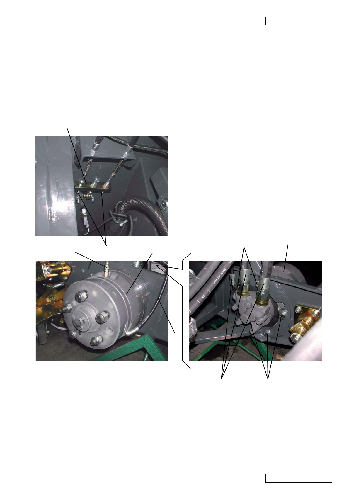
SERVICE MANUAL
ENGLISH
DRIVE SYSTEM
DRIVE SYSTEM MOTOR DISASSEMBLY/ASSEMBLY
Remove the suction inlet (see the procedure in the relevant paragraph).
1.
Remove the front wheel (see the procedure in the relevant paragraph). Place safety stands under the machine side sill, on the
2.
side where the wheel has been removed.
3.
Disconnect the brake system pipes (A) from the brake assembly (B) and plug them immediately.
4.
Remove the right or left nut (E), then disconnect the parking brake control cable (C) from the bracket (D).
5.
Disconnect the hoses (F) from the drive system motor (B) and plug them immediately.
6.
Remove fi ve screws (G), then remove the drive system motor (B) together with the brake.
7.
Assemble the components in the reverse order of disassembly and note the following:
•
Before assembling the wheel, bleed the brake system (see the procedure in the relevant paragraph).
8.
Check the brake system (see the procedure in the relevant paragraph).
9.
Adjust the parking brake (see the procedure in the relevant paragraph).
D
A
E
B
C
G
F
G
B
S300891
RS 501 33015500(3)2008-02
69
Page 72

ENGLISH
SERVICE MANUAL
DRIVE SYSTEM
DRIVE PEDAL CHECK AND ADJUSTMENT
Preliminary operations
Empty the hopper (3); if it contains a small quantity of waste, it is not necessary to dump it.
1.
Check
Drive the machine on a level and smooth ground, and, with the engine on, check that the machine does not move forward or
2.
backward when the drive pedal (56) is not pressed.
If the machine moves, even though slightly, check the drive pedal, according to the following procedure.
Drive pedal check
Engage the parking brake with the lever (66).
3.
Turn the ignition key (76) to OFF position.
4.
Check that the drive pedal (56) turns freely on its shaft and that it does not bind/slow down, which may prevent the pedal from
5.
resuming the neutral position.
If necessary, remove the possible cause for binding/slowing down, then repeat step 1.
If the problem persists, adjust the drive system pump as shown below.
Drive system pump adjustment
Disengage the parking brake with the lever (66).
6.
Stop the left front wheel with two wedges (A).
7.
Remove the right front wheel according to the procedure shown in the relevant paragraph.
8.
Place safety stands under the machine side sill, on the side where the wheel has been removed.
9.
Lift the hopper (3) for 20 cm, according to the procedure shown in the User Manual.
10.
Turn the ignition key (76) to OFF position and remove it.
11.
Open the right lid (20) by releasing the fasteners (21) with the supplied key.
12.
Empty the dust control system water tanks (7 and 16) according to the procedure shown in the relevant paragraph.
13.
Remove the screw (44) and open the right tank (43).
14.
WARNING!
Open the tanks (7 and 16) only if they are empty: each tank contains 120 kg of water approximately.
Turn on the diesel engine with care.
15.
WARNING!
When the diesel engine is running, the wheel hub (B) can be rotating.
Check that the machine is in the following conditions:
16.
Diesel engine is running
•
Drive pedal (56) is not pressed
•
Brakes and parking brake are not activated
•
In these conditions, operating on the drive system pump (C), loosen the locknut (D) then turn the threaded dowel (E) clockwise
or counter-clockwise, until the hub (B) stops.
Tighten the locknut (D).
Engage the parking brake with the lever (66).
17.
Turn the ignition key (76) to OFF position.
18.
Perform steps 6 to 12 in the reverse order.
19.
Perform step 1 again.
20.
If necessary, fi ll the dust control system water tanks according to the procedure shown in the User Manual.
21.
70
33015500(3)2008-02 RS 501
Page 73

DRIVE PEDAL CHECK AND ADJUSTMENT (Continues)
SERVICE MANUAL
A
ENGLISH
DRIVE SYSTEM
B
C
D
E
RS 501 33015500(3)2008-02
S301494
71
Page 74

ENGLISH
DRIVE SYSTEM
SERVICE MANUAL
72
33016312(0)2007-04 RS 501 UK
Page 75
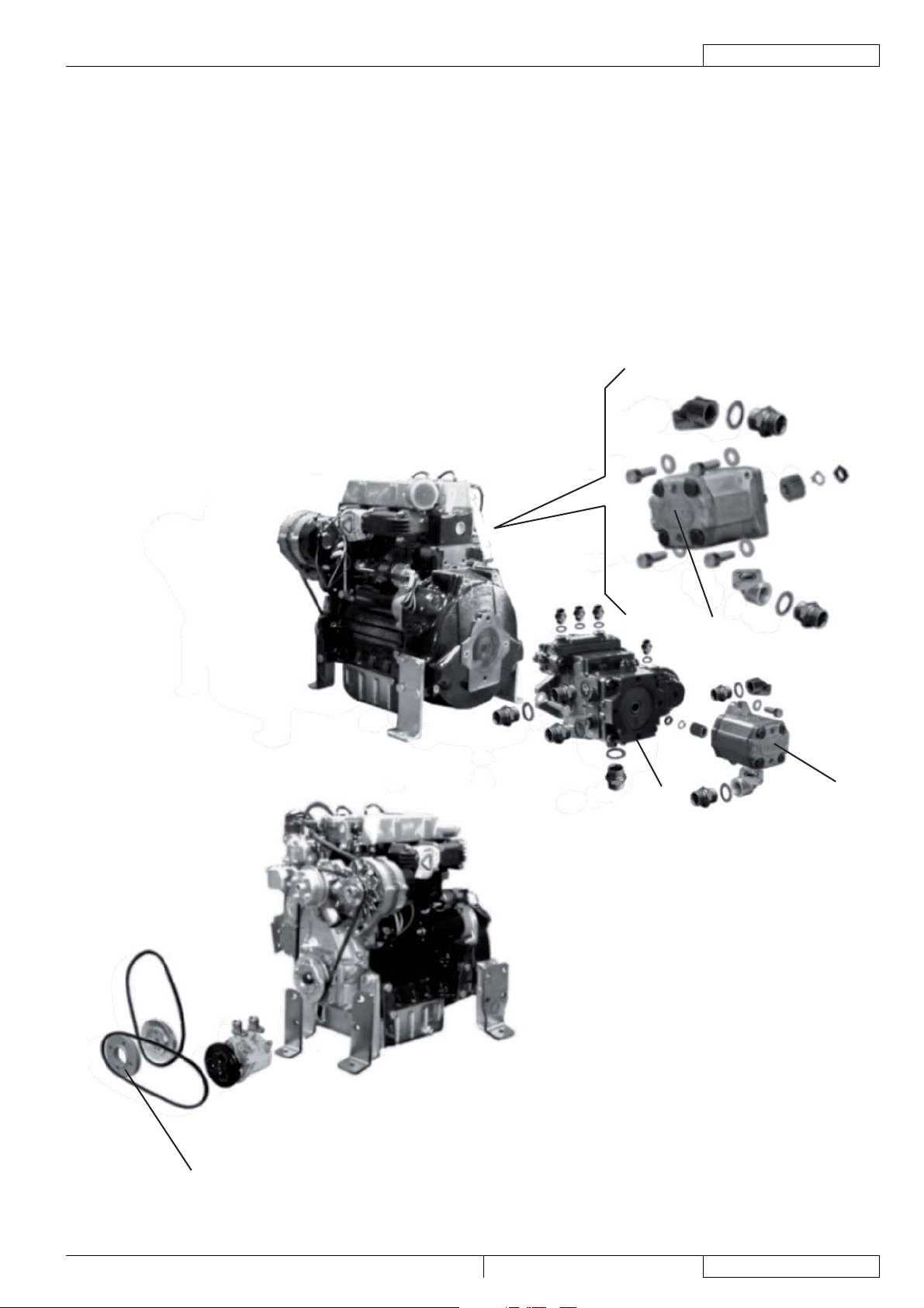
SERVICE MANUAL
ENGLISH
LDW 1603/B2 ENGINE
LDW 1603/B2 ENGINE
DESCRIPTION
The machine is equipped with a diesel engine, which activates the hydraulic system pumps.
For diesel engine data see the Technical Data chapter and the Diesel Engine Manual.
The following pumps are connected to the engine:
A)
Accessory and steering system pump
B)
Suction fan pump
Drive system pump
C)
The fuel fi lter is located on the machine frame.
For machines equipped with climate control system, besides the alternator control pulley, there is also the compressor control pulley
(D).
C
A
B
D
RS 501 33015500(3)2008-02
S301413
73
Page 76

ENGLISH
SERVICE MANUAL
LDW 1603/B2 ENGINE
TROUBLESHOOTING
The diesel engine does not start
Possible causes:
1.
The drive pedal is pressed (release).
The sensor for engine start-up inhibition is misadjusted/broken (adjust/replace).
2.
NOTE
For diesel engine complete troubleshooting, see the relevant Manual.
74
33015500(3)2008-02 RS 501
Page 77

SERVICE MANUAL
LDW 1603/B2 ENGINE
ENGINE OIL LEVEL CHECK
Empty the hopper (3); if it contains a small quantity of waste, it is not necessary to dump it.
1.
Drive the machine on a solid and level ground, then engage the parking brake with the lever (66).
2.
Lift the hopper (3), according to the procedure shown in the User Manual.
3.
Turn the ignition key (76) to OFF position and remove it.
4.
Open the left lid (18) by releasing the fasteners (19) with the supplied key.
5.
Remove the locking pins (28) from the housings (29) and place them into the holes (30).
6.
Empty the dust control system water tanks (7 and 16) according to the procedure shown in the relevant paragraph.
7.
Remove the screw (49) and open the left tank (41).
8.
WARNING!
Open the tanks (7 and 16) only if they are empty: each tank contains 120 kg of water approximately.
Check the oil level according to the procedure shown in the Diesel Engine Manual.
9.
If necessary, add oil according to the procedure shown in the Diesel Engine Manual.
10.
Perform steps 3, 4, 5, 6 and 8 in the reverse order.
11.
If necessary, fi ll the dust control system water tanks according to the procedure shown in the User Manual.
12.
ENGLISH
RS 501 33015500(3)2008-02
75
Page 78

ENGLISH
SERVICE MANUAL
LDW 1603/B2 ENGINE
ENGINE OIL CHANGE
Empty the hopper (3); if it contains a small quantity of waste, it is not necessary to dump it.
1.
Drive the machine on a solid and level ground, then engage the parking brake with the lever (66).
2.
Lift the hopper (3), according to the procedure shown in the User Manual.
3.
Turn the ignition key (76) to OFF position and remove it.
4.
Open the right and left lids (20) and (18) by releasing the fasteners (21) and (19) with the supplied key.
5.
Remove the locking pins (28) from the housings (29) and place them into the holes (30).
6.
Empty the dust control system water tanks (7 and 16) according to the procedure shown in the relevant paragraph.
7.
Remove the screw (44) and open the right tank (43).
8.
WARNING!
Open the tanks (7 and 16) only if they are empty: each tank contains 120 kg of water approximately.
Change oil according to the procedure shown in the Diesel Engine Manual.
9.
Perform steps 3, 4, 5, 6 and 8 in the reverse order.
10.
If necessary, fi ll the dust control system water tanks according to the procedure shown in the User Manual.
11.
76
33015500(3)2008-02 RS 501
Page 79

SERVICE MANUAL
LDW 1603/B2 ENGINE
ENGINE OIL FILTER CHANGE
NOTE
This procedure must be performed when the engine oil has been drained.
Empty the hopper (3); if it contains a small quantity of waste, it is not necessary to dump it.
1.
Drive the machine on a solid and level ground, then engage the parking brake with the lever (66).
2.
Lift the hopper (3), according to the procedure shown in the User Manual.
3.
Turn the ignition key (76) to OFF position and remove it.
4.
Open the left lid (18) by releasing the fasteners (19) with the supplied key.
5.
Remove the locking pins (28) from the housings (29) and place them into the holes (30).
6.
Empty the dust control system water tanks (7 and 16) according to the procedure shown in the relevant paragraph.
7.
8.
Remove the screw (42) and open the left tank (41).
WARNING!
Open the tanks (7 and 16) only if they are empty: each tank contains 120 kg of water approximately.
Replace the oil fi lter according to the procedure shown in the Diesel Engine Manual.
9.
Perform steps 3, 4, 5, 6 and 8 in the reverse order.
10.
If necessary, fi ll the dust control system water tanks according to the procedure shown in the User Manual.
11.
ENGLISH
RS 501 33015500(3)2008-02
77
Page 80

ENGLISH
SERVICE MANUAL
LDW 1603/B2 ENGINE
ENGINE COOLANT LEVEL CHECK
Empty the hopper (3); if it contains a small quantity of waste, it is not necessary to dump it.
1.
Drive the machine on a solid and level ground, then engage the parking brake with the lever (66).
2.
Lift the hopper (3), according to the procedure shown in the User Manual.
3.
Turn the ignition key (76) to OFF position and remove it.
4.
Open the left lid (18) by releasing the fasteners (19) with the supplied key.
5.
Remove the locking pins (28) from the housings (29) and place them into the holes (30).
6.
WARNING!
The coolant line is pressurised; do not perform any check until the engine has cooled down and, even if the
engine is cold, the tank plug (B) must be opened with extreme care.
Check that the coolant level in the tank (A) is between the minimum and maximum marks, according to the procedure shown
7.
in the Diesel Engine Manual. If necessary, unscrew the plug (B) and top up.
Coolant components:
•
50% of AGIP antifreeze
50% of water
•
After top up, tighten the plug (B).
8.
Perform steps 3 to 6 in the reverse order.
B
A
S300894
78
33015500(3)2008-02 RS 501
Page 81

SERVICE MANUAL
LDW 1603/B2 ENGINE
ENGINE AIR FILTER CLEANING
WARNING!
Protect body parts (eyes, hair, hands, etc.) properly, when performing cleaning operations using compressed air
gun.
Preliminary operations
1.
Engage the parking brake with the lever (66).
2.
Turn the ignition key (76) to OFF position and remove it.
3.
Open the left lid (18) by releasing the fasteners (19) with the supplied key.
Pre-fi lter cleaning
4.
Remove the screw (A), then remove the pre-fi lter (B).
5.
Clean and wash the pre-fi lter, then install it.
Filter cleaning
6.
Remove the screw (C), then remove the cover (D).
7.
Remove the outer fi lter (E) and the inner fi lter (F).
8.
Clean the fi lters (E) and (F) carefully with compressed air (maximum 6 Bar) and replace them, if necessary.
9.
Install the fi lters (E) and (F).
10.
Install the cover (D) and the screw (C).
11.
Close the left lid (18) by engaging the fasteners (19) with the supplied key.
A
B
C
ENGLISH
D
E
F
S300895
RS 501 33015500(3)2008-02
79
Page 82

ENGLISH
SERVICE MANUAL
LDW 1603/B2 ENGINE
FUEL FILTER REPLACEMENT
Empty the hopper (3); if it contains a small quantity of waste, it is not necessary to dump it.
1.
Drive the machine on a solid and level ground, then engage the parking brake with the lever (66).
2.
Lift the hopper (3), according to the procedure shown in the User Manual.
3.
Turn the ignition key (76) to OFF position and remove it.
4.
Open the left lid (18) by releasing the fasteners (19) with the supplied key.
5.
Remove the locking pins (28) from the housings (29) and place them into the holes (30).
6.
Empty the dust control system water tanks (7 and 16) according to the procedure shown in the relevant paragraph.
7.
Remove the screw (42) and open the left tank (41).
8.
WARNING!
Open the tanks (7 and 16) only if they are empty: each tank contains 120 kg of water approximately.
Replace the fuel fi lter according to the procedure shown in the Diesel Engine Manual.
9.
Perform steps 3, 4, 5, 6 and 8 in the reverse order.
10.
If necessary, fi ll the dust control system water tanks according to the procedure shown in the User Manual.
11.
80
33015500(3)2008-02 RS 501
Page 83

SERVICE MANUAL
ENGLISH
LDW 1603/B2 ENGINE
FUEL FITTING AND SCREW CHECK
Empty the hopper (3); if it contains a small quantity of waste, it is not necessary to dump it.
1.
Drive the machine on a solid and level ground, then engage the parking brake with the lever (66).
2.
Lift the hopper (3), according to the procedure shown in the User Manual.
3.
Turn the ignition key (76) to OFF position and remove it.
4.
Open the left lid (18) by releasing the fasteners (19) with the supplied key.
5.
Remove the locking pins (28) from the housings (29) and place them into the holes (30).
6.
Empty the dust control system water tanks (7 and 16) according to the procedure shown in the relevant paragraph.
7.
Remove the screw (42) and open the left tank (41).
8.
WARNING!
Open the tanks (7 and 16) only if they are empty: each tank contains 120 kg of water approximately.
Operating on the fuel fi lter (A) and on the diesel engine, check the sealing of fuel system fi ttings (B). Repair if necessary.
9.
Operating on the fuel tank (C), check the sealing of fuel system fi ttings (D). Repair if necessary.
10.
Perform steps 3, 4, 5, 6 and 8 in the reverse order.
11.
If necessary, fi ll the dust control system water tanks according to the procedure shown in the User Manual.
12.
B
B
B
B
A
B
D
C
B
D
S301656
RS 501 33015500(3)2008-02
81
Page 84

ENGLISH
SERVICE MANUAL
LDW 1603/B2 ENGINE
ALTERNATOR BELT TENSION CHECK
Empty the hopper (3); if it contains a small quantity of waste, it is not necessary to dump it.
1.
Drive the machine on a solid and level ground, then engage the parking brake with the lever (66).
2.
Lift the hopper (3), according to the procedure shown in the User Manual.
3.
Turn the ignition key (76) to OFF position and remove it.
4.
Open the right lid (20) by releasing the fasteners (21) with the supplied key.
5.
Remove the locking pins (28) from the housings (29) and place them into the holes (30).
6.
Empty the dust control system water tanks (7 and 16) according to the procedure shown in the relevant paragraph.
7.
Remove the screw (44) and open the right tank (43).
8.
WARNING!
Open the tanks (7 and 16) only if they are empty: each tank contains 120 kg of water approximately.
Check and, if necessary, adjust the alternator belt tension according to the procedure shown in the Diesel Engine Manual.
9.
Perform steps 3, 4, 5, 6 and 8 in the reverse order.
10.
If necessary, fi ll the dust control system water tanks according to the procedure shown in the User Manual.
11.
82
33015500(3)2008-02 RS 501
Page 85

SERVICE MANUAL
LDW 1603/B2 ENGINE
ALTERNATOR BELT REPLACEMENT
Empty the hopper (3); if it contains a small quantity of waste, it is not necessary to dump it.
1.
Drive the machine on a solid and level ground, then engage the parking brake with the lever (66).
2.
Lift the hopper (3), according to the procedure shown in the User Manual.
3.
Turn the ignition key (76) to OFF position and remove it.
4.
Open the right lid (20) by releasing the fasteners (21) with the supplied key.
5.
Remove the locking pins (28) from the housings (29) and place them into the holes (30).
6.
Empty the dust control system water tanks (7 and 16) according to the procedure shown in the relevant paragraph.
7.
Remove the screw (44) and open the right tank (43).
8.
WARNING!
Open the tanks (7 and 16) only if they are empty: each tank contains 120 kg of water approximately.
Replace and adjust the alternator belt tension according to the procedure shown in the Diesel Engine Manual.
9.
Perform steps 3, 4, 5, 6 and 8 in the reverse order.
10.
If necessary, fi ll the dust control system water tanks according to the procedure shown in the User Manual.
11.
ENGLISH
RS 501 33015500(3)2008-02
83
Page 86

ENGLISH
SERVICE MANUAL
LDW 1603/B2 ENGINE
RADIATOR FIN CLEANING CHECK
Empty the hopper (3); if it contains a small quantity of waste, it is not necessary to dump it.
1.
Drive the machine on a solid and level ground, then engage the parking brake with the lever (66).
2.
Lift the hopper (3), according to the procedure shown in the User Manual.
3.
Turn the ignition key (76) to OFF position and remove it.
4.
Open the right and left lids (20) and (18) by releasing the fasteners (21) and (19) with the supplied key.
5.
Remove the locking pins (28) from the housings (29) and place them into the holes (30).
6.
Empty the dust control system water tanks (7 and 16) according to the procedure shown in the relevant paragraph.
7.
On both sides of the machine, loosen the screws (42 and 44), and open the right and left tanks (41 and 43).
8.
WARNING!
Open the tanks (7 and 16) only if they are empty: each tank contains 120 kg of water approximately.
Check the radiator fi n cleaning according to the procedure shown in the Diesel Engine Manual.
9.
Perform steps 3, 4, 5, 6 and 8 in the reverse order.
10.
If necessary, fi ll the dust control system water tanks according to the procedure shown in the User Manual.
11.
84
33015500(3)2008-02 RS 501
Page 87

SERVICE MANUAL
LDW 1603/B2 ENGINE
ENGINE COOLANT LINE SLEEVE CHECK
Empty the hopper (3); if it contains a small quantity of waste, it is not necessary to dump it.
1.
Drive the machine on a solid and level ground, then engage the parking brake with the lever (66).
2.
Lift the hopper (3), according to the procedure shown in the User Manual.
3.
Turn the ignition key (76) to OFF position and remove it.
4.
Open the right and left lids (20) and (18) by releasing the fasteners (21) and (19) with the supplied key.
5.
Remove the locking pins (28) from the housings (29) and place them into the holes (30).
6.
Empty the dust control system water tanks (7 and 16) according to the procedure shown in the relevant paragraph.
7.
Remove the screws (44) and (42) and open the right (43) and left tank (41).
8.
WARNING!
Open the tanks (7 and 16) only if they are empty: each tank contains 120 kg of water approximately.
Check the coolant line sleeves according to the procedure shown in the Diesel Engine Manual.
9.
Perform steps 3, 4, 5, 6 and 8 in the reverse order.
10.
If necessary, fi ll the dust control system water tanks according to the procedure shown in the User Manual.
11.
ENGLISH
RS 501 33015500(3)2008-02
85
Page 88

ENGLISH
SERVICE MANUAL
LDW 1603/B2 ENGINE
ENGINE COOLANT CHANGE
Empty the hopper (3); if it contains a small quantity of waste, it is not necessary to dump it.
1.
Drive the machine on a solid and level ground, then engage the parking brake with the lever (66).
2.
Lift the hopper (3), according to the procedure shown in the User Manual.
3.
Turn the ignition key (76) to OFF position and remove it.
4.
Open the right and left lids (20) and (18) by releasing the fasteners (21) and (19) with the supplied key.
5.
Remove the locking pins (28) from the housings (29) and place them into the holes (30).
6.
Empty the dust control system water tanks (7 and 16) according to the procedure shown in the relevant paragraph.
7.
Remove the screw (42) and open the left tank (41).
8.
WARNING!
Open the tanks (7 and 16) only if they are empty: each tank contains 120 kg of water approximately.
Change the engine coolant according to the procedure shown in the Diesel Engine Manual.
9.
Perform steps 3, 4, 5, 6 and 8 in the reverse order.
10.
If necessary, fi ll the dust control system water tanks according to the procedure shown in the User Manual.
11.
86
33015500(3)2008-02 RS 501
Page 89

SERVICE MANUAL
LDW 1603/B2 ENGINE
INJECTOR CALIBRATION AND CLEANING
Empty the hopper (3); if it contains a small quantity of waste, it is not necessary to dump it.
1.
Drive the machine on a solid and level ground, then engage the parking brake with the lever (66).
2.
Lift the hopper (3), according to the procedure shown in the User Manual.
3.
Turn the ignition key (76) to OFF position and remove it.
4.
Open the left lid (18) by releasing the fasteners (19) with the supplied key.
5.
Remove the locking pins (28) from the housings (29) and place them into the holes (30).
6.
Empty the dust control system water tanks (7 and 16) according to the procedure shown in the relevant paragraph.
7.
Remove the screw (42) and open the left tank (41).
8.
WARNING!
Open the tanks (7 and 16) only if they are empty: each tank contains 120 kg of water approximately.
Calibrate and clean the injectors according to the procedure shown in the Diesel Engine Manual.
9.
Perform steps 3 to 6 and 8 in the reverse order.
10.
If necessary, fi ll the dust control system water tanks according to the procedure shown in the User Manual.
11.
ENGLISH
RS 501 33015500(3)2008-02
87
Page 90

ENGLISH
SERVICE MANUAL
LDW 1603/B2 ENGINE
88
33016312(0)2007-04 RS 501 UK
Page 91

CLIMATE CONTROL SYSTEM
DESCRIPTION
The climate control system consists of:
A)
Compressor
B)
Condenser
Cooler
C)
Expansion valve
D)
Filter drier
E)
High pressure hose
F)
Low pressure hose
G)
High pressure connection
H)
Low pressure connection
I)
Cooling controls
J)
Heating controls
K)
Heater
L)
Air fi lter
M)
SERVICE MANUAL
ENGLISH
CLIMATE CONTROL SYSTEM
J
K
L
M
E
B
F
H
G
A
I
D
C
S300899
RS 501 33015500(3)2008-02
89
Page 92

ENGLISH
SERVICE MANUAL
CLIMATE CONTROL SYSTEM
TROUBLESHOOTING
No fresh air from the climate control system
Possible causes:
The compressor does not turn because the drive belt is loosen/broken (tension/replace the belt).
1.
There are gas leaks from the system (repair the leak and integrate the gas).
2.
The expansion valve is faulty (replace).
3.
No hot air from the climate control system
Possible causes:
The hot water hoses are broken (replace).
1.
There are water leaks from the heater (replace).
2.
90
33015500(3)2008-02 RS 501
Page 93

SERVICE MANUAL
CLIMATE CONTROL SYSTEM
COMPRESSOR BELT TENSION CHECK (LDW 1603/B2 engine)
Empty the hopper (3); if it contains a small quantity of waste, it is not necessary to dump it.
1.
Drive the machine on a solid and level ground, then engage the parking brake with the lever (66).
2.
Lift the hopper (3), according to the procedure shown in the User Manual.
3.
Turn the ignition key (76) to OFF position and remove it.
4.
Open the right lid (20) by releasing the fasteners (21) with the supplied key.
5.
Remove the locking pins (28) from the housings (29) and place them into the holes (30).
6.
Empty the dust control system water tanks (7 and 16) according to the procedure shown in the relevant paragraph.
7.
Remove the screw (44) and open the right tank (43).
8.
WARNING!
Open the tanks (7 and 16) only if they are empty: each tank contains 120 kg of water approximately.
Check the tension of the belt (A) of the compressor (B) according to the following procedure:
9.
Press the belt in the intermediate position (C) with a force of 10 kg and check that the belt does not bend for more than 1
•
cm.
If necessary, loosen the nuts (D) and (E), and adjust the tension of the belt (A). Tighten the nuts (D) and (E).
Perform steps 3, 4, 5, 6 and 8 in the reverse order.
10.
If necessary, fi ll the dust control system water tanks according to the procedure shown in the User Manual.
11.
ENGLISH
C
A
D
B
E
S301415
RS 501 33015500(3)2008-02
91
Page 94
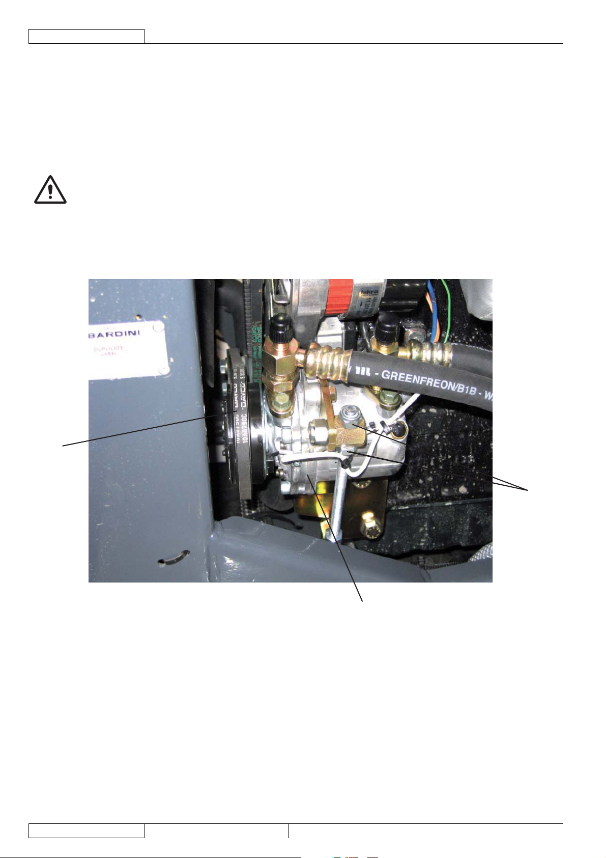
ENGLISH
A
SERVICE MANUAL
CLIMATE CONTROL SYSTEM
COMPRESSOR BELT REPLACEMENT (LDW 1603/B2 engine)
Empty the hopper (3); if it contains a small quantity of waste, it is not necessary to dump it.
1.
Drive the machine on a solid and level ground, then engage the parking brake with the lever (66).
2.
Lift the hopper (3), according to the procedure shown in the User Manual.
3.
Turn the ignition key (76) to OFF position and remove it.
4.
Open the left lid (18) by releasing the fasteners (19) with the supplied key.
5.
Remove the locking pins (28) from the housings (29) and place them into the holes (30).
6.
Empty the dust control system water tanks (7 and 16) according to the procedure shown in the relevant paragraph.
7.
Remove the screw (42) and open the left tank (41).
8.
WARNING!
Open the tanks (7 and 16) only if they are empty: each tank contains 120 kg of water approximately.
Loosen the tensioning nuts (A) of the belt (B) of the compressor (C).
9.
Remove the belt (B) from the pulleys.
10.
Place the new belt (B) on the pulleys.
11.
Adjust the compressor belt tension according to the procedure shown in the previous paragraph.
12.
Perform steps 3, 4, 5, 6 and 8 in the reverse order.
13.
If necessary, fi ll the dust control system water tanks according to the procedure shown in the User Manual.
14.
B
C
S301415
92
33015500(3)2008-02 RS 501
Page 95

SERVICE MANUAL
AIR FILTER REPLACEMENT
Engage the parking brake with the lever (66).
1.
Turn the ignition key (76) to OFF position and remove it.
2.
Remove the screws (A) and the panel (B) in the cab.
3.
Unscrew the knobs (F) and remove the panel (C).
4.
Remove the cab air fi lter (D).
5.
Install the new fi lter (D) with the arrows (E) pointing in the direction of the air fl ow (upwards).
6.
Perform steps 3 and 4 in the reverse order.
7.
A
B
A
F
ENGLISH
CLIMATE CONTROL SYSTEM
C
F
A
D
A
E
S300902
RS 501 33015500(3)2008-02
93
Page 96

ENGLISH
SERVICE MANUAL
CLIMATE CONTROL SYSTEM
94
33016312(0)2007-04 RS 501 UK
Page 97

SERVICE MANUAL
OTHER SYSTEMS
OTHER SYSTEMS
NUT AND SCREW TIGHTENING AND LEAKAGE CHECK
Empty the hopper (3); if it contains a small quantity of waste, it is not necessary to dump it.
1.
Drive the machine on a solid and level ground, then engage the parking brake with the lever (66).
2.
Open the right and left lids (20) and (18) by releasing the fasteners (21) and (19) with the supplied key.
3.
Lift the hopper (3), according to the procedure shown in the User Manual.
4.
Turn the ignition key (76) to OFF position and remove it.
5.
Remove the locking pins (28) from the housings (29) and place them into the holes (30).
6.
Empty the dust control system water tanks (7 and 16) according to the procedure shown in the relevant paragraph.
7.
Remove the screw (44) and open the right tank (43).
8.
WARNING!
Open the tanks (7 and 16) only if they are empty: each tank contains 120 kg of water approximately.
Remove the screw (42) and open the left tank (41).
9.
Inspect the machine accessible parts and check for:
10.
Tightening of mounting screws and nuts;
•
Correct position of the fasteners;
•
Visible faults in the components;
•
Leaks of fl uids (oil, etc.).
•
Perform steps 3, 4, 5, 6 and 8 in the reverse order.
11.
If necessary, fi ll the dust control system water tanks according to the procedure shown in the User Manual.
12.
ENGLISH
RS 501 33015500(3)2008-02
95
Page 98

ENGLISH
SERVICE MANUAL
OTHER SYSTEMS
LUBRICATION
Drive the machine on a solid and level ground, then engage the parking brake with the lever (66).
1.
Turn the ignition key (76) to OFF position and remove it.
2.
Lubricate the rear axle knuckles with the grease nipples (A). If necessary, steer the rear wheels to reach the grease nipples
3.
easily.
Grease quantity to be applied:
•
2 - 3 pumping, in case of a manual pump.
•
8 - 12 seconds of injection, in case of an air pump.
A
A
A
A
S300903
96
33015500(3)2008-02 RS 501
Page 99

SERVICE MANUAL
ENGLISH
OTHER SYSTEMS
CHECK AND ADJUSTMENT OF SENSOR FOR ENGINE START-UP INHIBITION WHEN THE DRIVE
PEDAL IS PRESSED
Check
1.
Check that it is not possible to start the machine with the ignition key (76) when the drive pedal (56) is pressed.
If necessary, adjust the relevant sensor according to the following procedure.
Adjustment
1.
Engage the parking brake with the lever (66).
2.
Turn the ignition key (76) to OFF position and remove it.
3.
Check that the surface (A) of the sensor (B) is fl ush with the surface (C) of the drive pedal.
If necessary, loosen the sensor mounting nut (D) and adjust the sensor position. When the adjustment is completed, tighten
the nut (D).
4.
Check that the distance between the sensor surface (A) and the bracket (E) is within 1.5 and 2.5 mm. When checking, move
the drive pedal (F) towards the bracket (E) to cancel the drive pedal end play.
If necessary, loosen the nuts (G) and the nut (H), and adjust the position of the bracket (E). When the adjustment is completed,
tighten the nuts (G) and (H).
5.
Perform step 1 again.
E
A
C
G
H
G
F
D
B
S301453
RS 501 33015500(3)2008-02
97
Page 100

ENGLISH
SERVICE MANUAL
OTHER SYSTEMS
DISASSEMBLY/ASSEMBLY OF SENSOR FOR ENGINE START-UP INHIBITION WHEN THE DRIVE
PEDAL IS PRESSED
Disassembly
1.
Engage the parking brake with the lever (66).
2.
Turn the ignition key (76) to OFF position and remove it.
3.
Cut the cable clamp (A) under the right side of the cab.
4.
Disconnect the connector (B) of the sensor for engine start-up inhibition (C).
5.
Remove the four mounting screws (D) of the drive pedal (E).
6.
Slightly lift the drive pedal (E) and remove the mounting nut (F) of the sensor (C).
7.
Remove the sensor (C), the harness (G) and the connector.
Assembly
8.
Assemble the components in the reverse order of disassembly.
9.
Adjust the sensor for engine start-up inhibition (see the procedure in the relevant paragraph).
AA
D
E
D
B
CG
F
S301416
98
33015500(3)2008-02 RS 501
 Loading...