

Page 1
RS 1300
Nilsk
RS 1300
by Nilsk Advance
Nilsk
ENGLISH INSTRUCTIONS FOR USE
FRANÇAIS INSTRUCTIONS D’UTILISATION
ESPAÑOL INSTRUCCIONES DE USO
PORTUGUÊS INSTRUÇÕES DE USO
RS 1300
by Nilsk Advance
33015124(3)2008-02
Page 2

Page 3
B
1
7
2
3
C
4
6
5
1
Model: RS 1300 Prod. Nr: 13300068
Serial No: 08XXXXXXX Date code : H07
Total Weight : KG 2800 IPX3 dB(A)79
KW 55 Battery: 12VDC
S310912
setting standards
24%
MAX
Manufactured By:
Nilfisk - Advance S.p.a.
26862 Guardamiglio (LO) - Italy
www.nilfisk-advance.com
Made in Italy
RS 1300 33015124(3)2008-02
S310810
I
Page 4
!
WARNING
D
50
49
7
8
51
10 11
9
18
35c
35b
32
54
35a
35
29
30
31
Risk of m
Sharp turns must be made at slowest possible speed.
achine tip-over and serious injury
Do not - Turn abruptly
- Turn on incline
- Turn w
Never raise hopper on incline.
Operating on incline or with weight in the hopper increases instability.
Regularly check tires for appropriate air pressure
ith hopper raised
6
5
4
15
16
17
3
28
2
12
13
14
1
25
24
23
27
21-53
22
34
26
acc
ording to Operator’s Manual.
19
33
20
52
47
38
39
37
36
41
40
48
43
42
44
45
46
S310913
II
33015124(3)2008-02 RS 1300
Page 5
E
2
4
2
3
8
15
16
14
19
6
5
9
13
1
17
RS 1300 33015124(3)2008-02
7
20
18
12
11
III
10
S310914
Page 6

F
39
46
28
1 21
19
18
17
16
12
15
13
14
40
44
27
31
32
3
33
11
25
22
5
3
6
20
24
41
37
7
38
8
37
30
42
29
26
IV
35
36 34
43
4
2
23
33015124(3)2008-02 RS 1300
10
38
9
45
S310915
Page 7
G
2
1
4
9
6
15
10
5
23
12
3
22
13
14
11
17
20
16
24
46 19
21
37 27 47
26
18
28
26
25
44
43
42
41
7
45
13 8
36
13
38
40
39
29
34
33
35
30
32
31
16
S310916
RS 1300 33015124(3)2008-02
V
Page 8
HI
1
2
S310917 S310816
J
L
K
S310817 S310818
M
1
N
VI
S310936 S310820
O
S310821 S310822
33015124(3)2008-02 RS 1300
Page 9
P
Q
S310823 S310824
R
T
S
S310825 S310826
U
V
S310827 S310918
W
S310829 S310830
RS 1300 33015124(3)2008-02
VII
Page 10
X
Y
S310831 S310832
Z
AB
AA
S310833
AC
VIII
S310920 S310919
S310921
33015124(3)2008-02 RS 1300
Page 11
AD AE
1
2
S310837 S310838
AF
10
12
11
AG
6
89
3
7
4
AH
5
12
S310840
2
1
4
3
AI
S311263 S310923
AJ
8
10
9
7
6
5
S310924 S310843
RS 1300 33015124(3)2008-02
IX
Page 12
AK
AL
AM1
1
DX
SX
2
2
S310925 S310937
1
AM2
AN
AP
S310846 S311277
AO
S310847 S310848
AQ
S310849 S310850
X
33015124(3)2008-02 RS 1300
Page 13
AR1
(->AR2)
(->AR2)
82
4
7
1
II 0 I
01C
3P2P
2F
8F
5F
4
7
11F
51F
6F
61F
21F
1F
5
2
0 I II
4C
2LT
OIDUA OVAC
1LT
NM
2R
7F
41F
05
45/51
3C
a78
03
68
58
580368
1R
0
3
2
1
0
SM
3
58
68
78
03
a78
9R
7
03
8
a78
58
68
8R
7R
a78
03
78
58
68
6R
01-100C
A
31F
78
4VE
3
VE
a7
8
03
78
68
58
02C
RP
02L
xP
61S
41
13191
8
14
51S
L 05 78 03 51 13
5 4 9 8 3 1
KC
+
B
02S
91S2G
1G
1B
03
58
4R
5S7S
4S3S
-
81S
a7868
21C
0358
78
68
21R
0358
22S
6S
2S1S
11R
78
68
01R
71C
61C
41C
31C
03
78
5
68
8
3
7
5
1
4
862
0
II
5C
52F
1C
0358
03
78
6
8
x
R
78
5
68
8
yR
2PM1PM41S
21S
VE
L
M
TM
1
CC
GE
31
S
BSK
1AT
81C
91C
W
D+B+
A
4K
3K2K
1
K
M
RS 1300 33015124(3)2008-02
S311279
XI
Page 14
AR2
9F01F
3F
8-100C
D
A
20D
4
E
8
4F
22F
12F
32F42F
3
7
2 0
1
8C
3 2 1 0
1D3/1
22C
4
6 2
8
1
3
5
7
2 1 0
7C
31L
12C
02F
91F
81F
71F
6 2
51
01
6C
1D3/1
10
9S
5
8
2
0
1
0
1
2
SR
C
30D
B
7
1
3
6
4
R
+
13
7R
03
MT
11C
8S
1D3/1
C
5R
78
68
58
P
2 0 1
2
C
V
E
1CVE
2CRM
71S
L
E
12S2
1
L
E
91L81L
11S
71L
61L
21L
11L
01L
9L
8L
7
L41L
01S
T51L
6L
5L4L
3L
2
L
1L
XII
(<-AR1)
(<-AR1)
S311280
33015124(3)2008-02 RS 1300
Page 15
AS
“A”
RS 1300 33015124(3)2008-02
“B”
S311281
XIII
Page 16
AT
96
96
91
91
89
100cc100cc
30bar
DX
SX
97
X
89
X
97
88
104
109
98
86
425cc 425cc
84
18bar
102
22cc
116
81
121
103
210bar
105
92
250bar
250bar
124
82
60µm
60µm 60µm
21cc
Lt.59.5
117
a
125µm
118 83
115
T
1P 2
b
2300
RPM
65cc
93
10µm
90
95
87
10µm
123
85
2480
RPM
M
101
11cc
6cc
100
130
bar
48.4
119
180bar
99
112
100cc
113
107
DX SX
97
X
97
X
94
51.6
90bar
80cc
108
57
108
DX
SX
98
150
bar
150
bar
114
111
110
94
120
121
122
122
106
130bar
S311278
XIV
33015124(3)2008-02 RS 1300
Page 17
AU
16
10
5
7
2
3
6
4
3
4
1
14
12
17
17a 17b
13
12
11
11
11
15
8
9
11
18
RS 1300 33015124(3)2008-02
S310930
XV
Page 18
AV
4
5
3
16
14
6
19
15
14
17
18
7
5
13
12
9
8
17
18
2
1
11
6
2-4 cm (0,8-1,6 inch)
20
21b
21
10
21a
22
XVI
S310931
33015124(3)2008-02 RS 1300
Page 19
AW
15
3
4
13
15
14
3
12
13
1
14
5
2
1
16
6
8
7
9
1011
17b
17
17a
18
RS 1300 33015124(3)2008-02
S310932
XVII
Page 20
AX
2
1
3
XVIII
4
5
S310933
33015124(3)2008-02 RS 1300
Page 21
AY
10
7
13
10
3
13
2
1
14
5
3
4
12
8
11
9
6
15
RS 1300 33015124(3)2008-02
S310934
XIX
Page 22
AZ
1
2
10
10
7
8
9
3
5
6
3
XX
34
S310935
33015124(3)2008-02 RS 1300
Page 23

INSTRUCTIONS FOR USE
ENGLISH
TABLE OF CONTENTS
INTRODUCTION ..............................................................................................................................................................3
MANUAL PURPOSE AND CONTENTS ..........................................................................................................................................3
TARGET ........................................................................................................................................................................................... 3
HOW TO KEEP THIS MANUAL ....................................................................................................................................................... 3
IDENTIFICATION DATA ...................................................................................................................................................................3
OTHER REFERENCE MANUALS ...................................................................................................................................................4
SPARE PARTS AND MAINTENANCE ............................................................................................................................................. 4
CHANGES AND IMPROVEMENTS ................................................................................................................................................4
SAFETY ...........................................................................................................................................................................4
SYMBOLS .......................................................................................................................................................................................4
GENERAL INSTRUCTIONS ............................................................................................................................................................5
UNP ACKING/DELIVERY .................................................................................................................................................7
MACHINE DESCRIPTION ...............................................................................................................................................7
OPERATION CAPABILITIES ...........................................................................................................................................................7
CONVENTIONS ..............................................................................................................................................................................7
DESCRIPTION ................................................................................................................................................................................8
TECHNICAL DATA ..........................................................................................................................................................................11
ENVIRONMENTAL CONDITIONS ................................................................................................................................................. 14
WIRING DIAGRAM ........................................................................................................................................................................15
3RD BROOM ARM WIRING DIAGRAM (*) ...................................................................................................................................16
ELECTRICAL FUSES ....................................................................................................................................................................17
ACCESSORIES/OPTIONS ............................................................................................................................................................17
USE ................................................................................................................................................................................18
GENERAL CAUTIONS ..................................................................................................................................................................18
BEFORE START-UP ......................................................................................................................................................................18
DIESEL ENGINE START AND STOP ............................................................................................................................................19
STARTING AND STOPPING THE MACHINE ...............................................................................................................................20
MACHINE OPERATION ................................................................................................................................................................23
HOPPER DUMPING ......................................................................................................................................................................24
USING THE REAR SUCTION PIPE (*) .........................................................................................................................................25
USING THE WINDSCREEN WIPER/WASHER ............................................................................................................................25
USING THE CAB HEATING ..........................................................................................................................................................25
USING THE CAB CLIMATE CONTROL SYSTEM (*) ....................................................................................................................25
LIGHTING SYSTEM OPERATION ................................................................................................................................................26
CEILING LIGHT OPERATION ....................................................................................................................................................... 26
3RD BROOM WORKING LIGHT OPERATION ............................................................................................................................. 26
HAZARD WARNING LIGHT OPERATION ....................................................................................................................................26
HOPPER MANUAL LIFTING .........................................................................................................................................................26
LIFTED HOPPER SUPPORT ROD INSTALLATION .....................................................................................................................27
LIFTED HOPPER LID SUPPORT ROD INSTALLATION ..............................................................................................................27
USING THE HIGH-PRESSURE WATER GUN (*) .........................................................................................................................27
USING THE CAMERA KIT (optional) ............................................................................................................................................. 28
AFTER USING THE MACHINE .....................................................................................................................................................28
DUST CONTROL SYSTEM WATER TANK EMPTYING ...............................................................................................................28
TOWING THE MACHINE ..............................................................................................................................................................29
TRANSPORTING BY TRAILER ....................................................................................................................................................29
MACHINE STORAGE ....................................................................................................................................................................29
FIRST PERIOD OF USE ...............................................................................................................................................................30
SALT SPREADER ASSEMBLY AND USE (optional) ..................................................................................................................... 30
SNOW BRUSH ASSEMBLY AND USE (optional) .........................................................................................................................31
SNOW CUTTER ASSEMBLY AND USE (optional) .......................................................................................................................32
RS 1300 33015124(3)2008-02
1
Page 24

ENGLISH
INSTRUCTIONS FOR USE
MAINTENANCE .............................................................................................................................................................33
SCHEDULED MAINTENANCE TABLE .........................................................................................................................................33
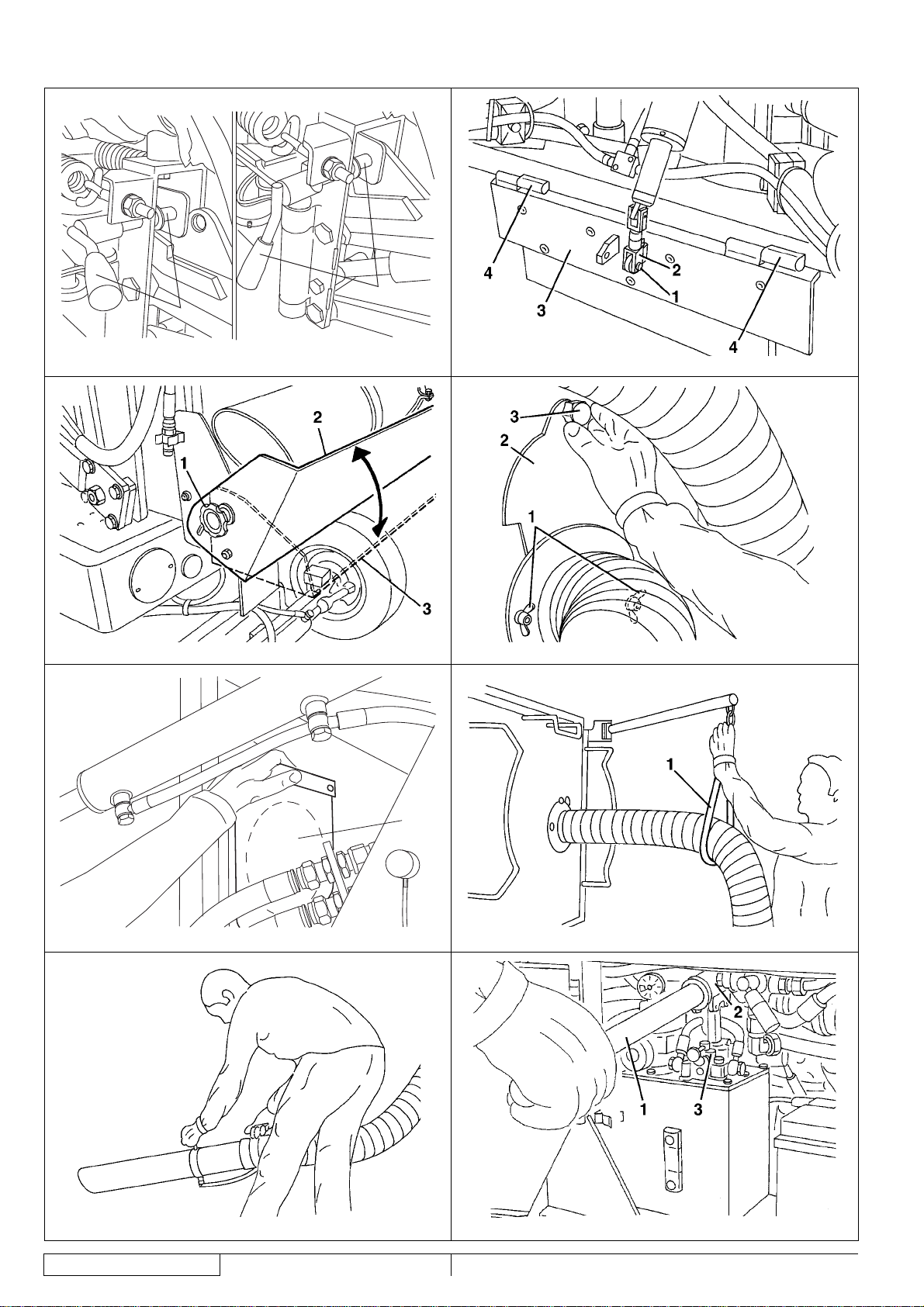
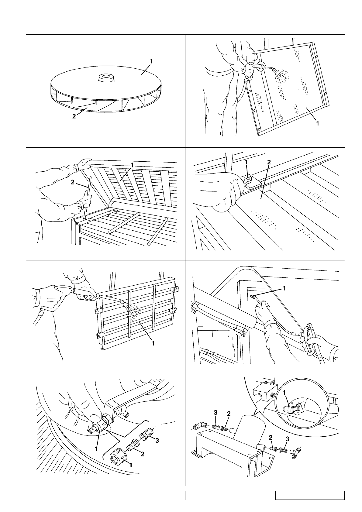
HOPPER, FILTER AND SUCTION PIPE CLEANING, GASKET CHECK AND SUCTION FAN BEARING LUBRICATION .........35
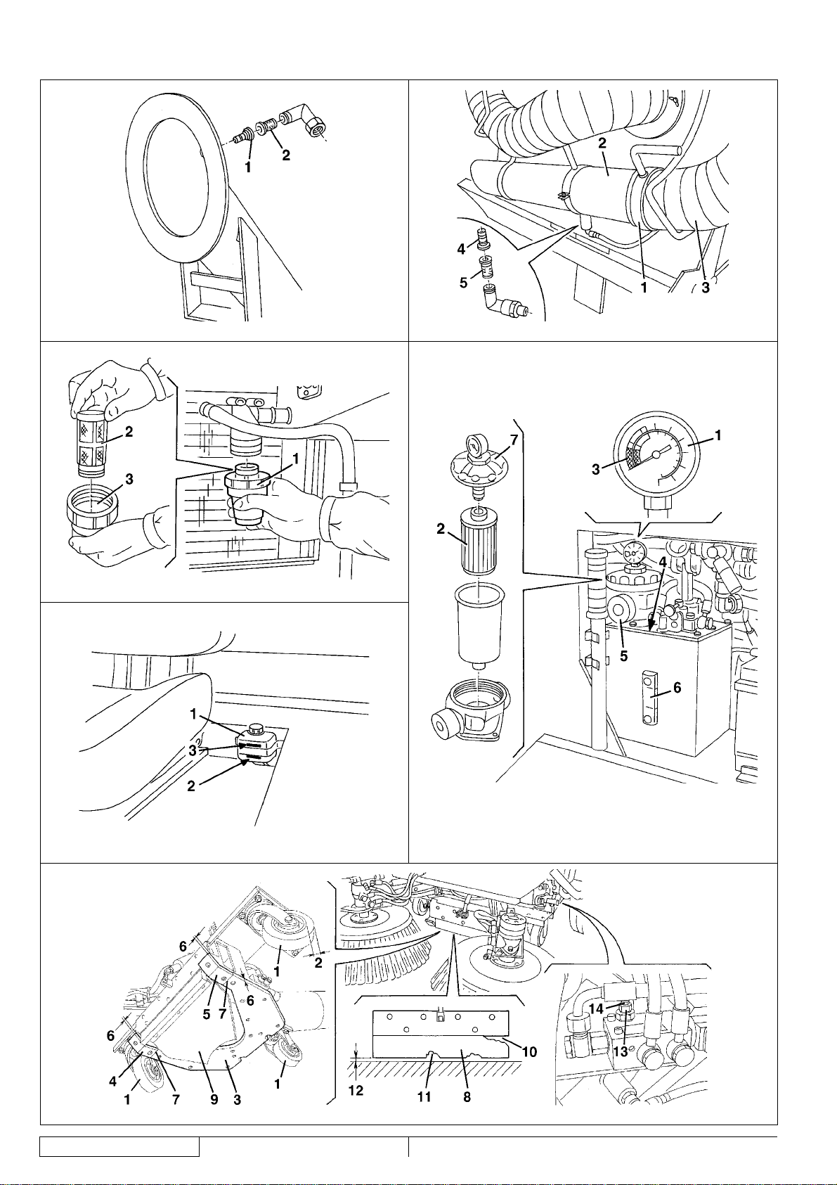
DUST CONTROL SYSTEM NOZZLE AND FILTER CLEANING ...................................................................................................36
DUST CONTROL SYSTEM WATER FILTER CLEANING .............................................................................................................37
HYDRAULIC SYSTEM OIL LEVEL CHECK ..................................................................................................................................37
HYDRAULIC SYSTEM OIL COOLER FIN CLEANING CHECK .................................................................................................... 37
BATTERY FLUID LEVEL CHECK ..................................................................................................................................................38
BRAKE FLUID LEVEL CHECK ......................................................................................................................................................38
REVERSE GEAR BUZZER SENSOR CHECK .............................................................................................................................38
TIRE PRESSURE CHECK ............................................................................................................................................................38
SUCTION INLET AND SKIRT HEIGHT AND OPERATION CHECK .............................................................................................38
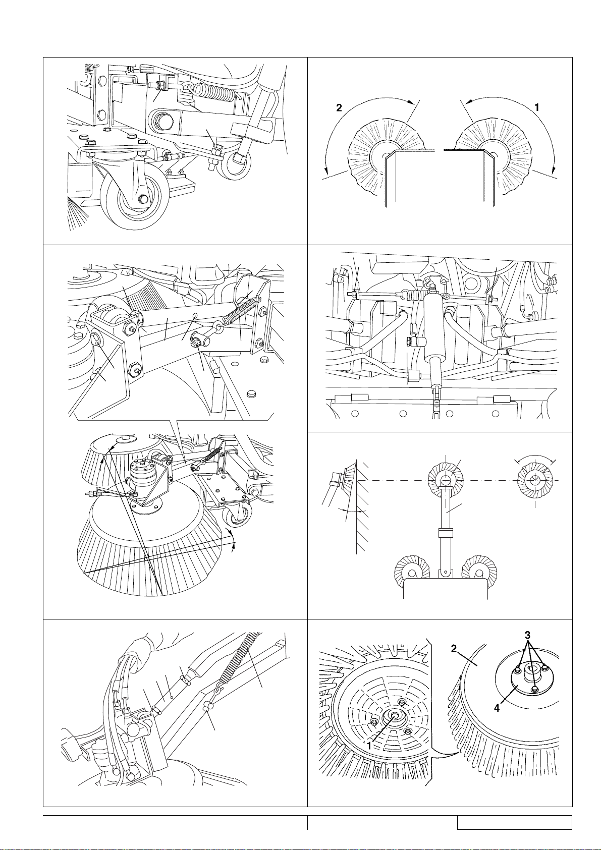
SIDE BROOM POSITION CHECK AND ADJUSTMENT ............................................................................................................... 39
3RD BROOM POSITION CHECK AND ADJUSTMENT ................................................................................................................40
BROOM REPLACEMENT .............................................................................................................................................................41
PARKING BRAKE CHECK ............................................................................................................................................................41
ENGINE OIL LEVEL CHECK .........................................................................................................................................................41
ENGINE OIL CHANGE ..................................................................................................................................................................41
ENGINE OIL FILTER REPLACEMENT .........................................................................................................................................41
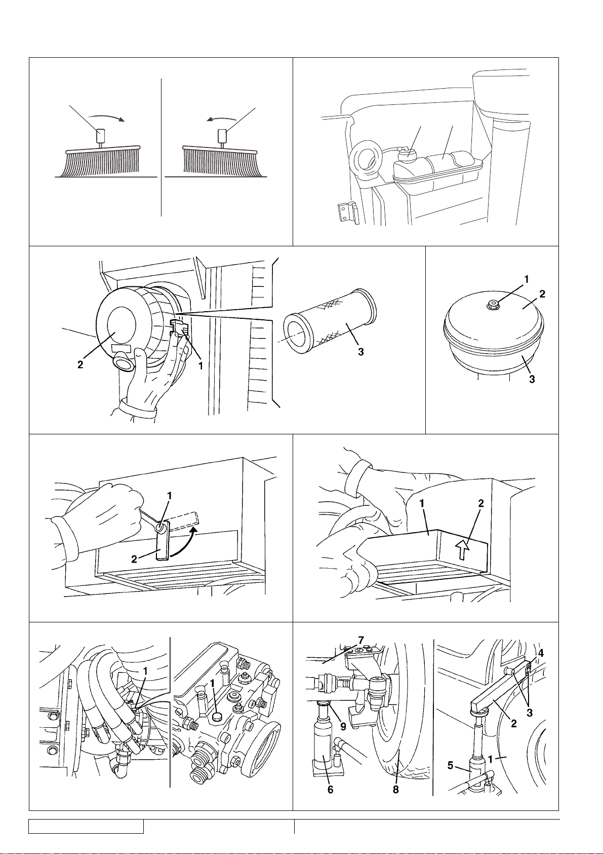
ENGINE AIR PRE-FILTER AND FILTER CLEANING .................................................................................................................... 42
ENGINE RADIATOR FIN CLEANING CHECK .............................................................................................................................. 42
ENGINE COOLANT LEVEL CHECK .............................................................................................................................................42
ENGINE FUEL FILTER REPLACEMENT ......................................................................................................................................43
CAB AIR FILTER REPLACEMENT ................................................................................................................................................43
WHEEL REPLACEMENT ..............................................................................................................................................................43
FUSE REPLACEMENT .................................................................................................................................................................44
SUCTION INLET DISASSEMBLY/ASSEMBLY .............................................................................................................................44
3RD BROOM ARM DISASSEMBLY/ASSEMBLY ..........................................................................................................................45
WINTER MAINTENANCE .............................................................................................................................................................45
SAFETY FUNCTIONS ................................................................................................................................................... 46
TROUBLESHOOTING ...................................................................................................................................................46
PROBLEMS AND REMEDIES .......................................................................................................................................................46
SCRAPPING ..................................................................................................................................................................50
2
33015124(3)2008-02 RS 1300
Page 25

INSTRUCTIONS FOR USE
ENGLISH
INTRODUCTION
MANUAL PURPOSE AND CONTENTS
This Manual is an integral part of the machine; its purpose is to provide the operator with all necessary information to use
the machine properly in a safe and autonomous way. It contains information about technical data, safety, operation, storage,
maintenance, spare parts and disposal.
Before performing any procedure on the machine, the operators and qualifi ed technicians must read this Manual carefully. Contact
Nilfi sk in case of doubts concerning the interpretation of the instructions and for any further information.
TARGET
This Manual is intended for operators and technicians qualifi ed to perform the machine maintenance.
The operators must not perform procedures reserved for qualifi ed technicians. Nilfi sk will not be responsible for damages coming
from failure to follow these instructions.
HOW TO KEEP THIS MANUAL
The Instructions for Use Manual must be kept inside the machine cab, away from liquids and other substances that can cause
damage to it.
IDENTIFICATION DATA
The machine serial number and model are shown on the adhesive label (1, Fig. C) and the plate (1, Fig. E) affi xed inside the cab.
The machine serial number is also printed on the machine side (33, Fig. G).
The diesel engine serial number and model are marked in the positions shown in the relevant Manual; in some countries, a plate
showing the same data is provided in the position (1, Fig. E).
This information is useful when ordering machine and diesel engine spare parts. Use the following table to write down the machine
and diesel engine identifi cation data for any further reference.
MACHINE model ...............................................................................
MACHINE serial number ...................................................................
ENGINE model ..................................................................................
ENGINE serial number ......................................................................
RS 1300 33015124(3)2008-02
3
Page 26
ENGLISH
INSTRUCTIONS FOR USE
OTHER REFERENCE MANUALS
The sweeper is also supplied with the following manuals:
–
Diesel Engine Manual (*)
–
Sweeper Spare Parts List
–
Salt Spreader Manual (optional) (*)
–
Salt Spreader Spare Parts List (optional)
–
Snow Brush Manual (optional) (*)
–
Snow Brush Spare Parts List (optional)
–
Snow Cutter Manual (optional) (*)
–
Snow Cutter Spare Parts List (optional)
–
Camera Kit Manual (optional) (*)
–
Camera Kit Spare Parts List (optional)
(*) These manuals are to be considered as integral part of the Sweeper Instructions for Use Manual.
At Nilfi sk Service Centers the following Manual is also available:
–
Sweeper Service Manual
SPARE PARTS AND MAINTENANCE
All necessary operating, maintenance and repair procedures must be performed by qualifi ed personnel or by Nilfi sk Service
Centers. Only original spare parts and accessories must be used.
Call Nilfi sk for service or to order spare parts and accessories, specifying the machine model and serial number.
CHANGES AND IMPROVEMENTS
Nilfi sk constantly improves its products and reserves the right to make changes and improvements at its discretion without being
obliged to apply such benefi ts to the machines that were previously sold.
Any change and/or addition of accessory must be approved and performed by Nilfi sk.
SAFETY
The following symbols indicate potentially dangerous situations. Always read this information carefully and take all necessary
precautions to safeguard people and property.
The operator’s cooperation is essential in order to prevent injury. No accident prevention program is effective without the total
cooperation of the person responsible for the machine operation. Most of the accidents that may occur while working or moving
around are caused by failure to comply with the simplest rules for exercising prudence. A careful and prudent operator is the best
guarantee against accidents and is essential for successful completion of any prevention program.
SYMBOLS
DANGER!
It indicates a dangerous situation with risk of death for the operator.
WARNING!
It indicates a potential risk of injury for people or damage to objects.
CAUTION!
It indicates a caution or a remark related to important or useful functions. Pay careful attention to the
paragraphs marked by this symbol.
NOTE
It indicates a remark related to important or useful functions.
CONSULTATION
It indicates that it is necessary to consult the Instructions for Use Manual before performing any procedure.
4
33015124(3)2008-02 RS 1300
Page 27

INSTRUCTIONS FOR USE
GENERAL INSTRUCTIONS
Specifi c warnings and cautions to inform about potential damages to people and machine are shown below.
DANGER!
−
This machine must be used by properly trained and authorised personnel only.
−
Moreover, the operator must:
•
Be 18 years or older
•
Have a driving license
•
Be in normal psycho-physical conditions
•
Not be under the effect of substances that alters the nervous system (alcohol, psycopharmaceuticals,
drugs, etc.)
−
Remove the ignition key before performing any maintenance/repair procedure.
−
This machine must be used by properly trained and authorised personnel only. Children or disabled people
cannot use this machine.
−
Do not wear jewels when working near moving parts.
−
Do not work under the lifted machine without supporting it with safety stands.
−
Do not operate the machine near toxic, dangerous, fl ammable and/or explosive powders, liquids or vapors.
−
Be careful, fuel is highly fl ammable.
−
Do not smoke or bring open fl ames in the area where the machine is refuelled or where the fuel is stored.
−
Refuel outdoors or in a well-ventilated area, with the engine off.
−
Do not fi ll the fuel tank to the top, but leave at least 1.6 in (4 cm) from the fi ller neck to allow the fuel to
expand.
−
After refuelling, check that the fi ller cap is tightly closed.
−
If any fuel is spilled while refuelling, clean up the affected area and allow the vapors to dissipate before
starting the engine.
−
Avoid contact with skin and do not breathe in fuel vapors. Keep out of reach of children.
−
Before performing any maintenance/repair procedure remove the ignition key, engage the parking brake and
disconnect the battery.
−
When working under open hoods/doors, make sure that they cannot be closed by accident.
−
When performing maintenance procedures with the lifted hopper, fi x it with the support rods.
−
During machine transportation, the fuel tank must not be full.
−
Diesel engine exhaust gases contain carbon monoxide, an extremely poisonous, colorless, and odorless
gas. Do not inhale. Do not keep the engine running in a closed area.
−
Do not lay any object on the engine.
−
Before working on the engine turn it off. To prevent the engine from starting accidentally, disconnect the
battery negative terminal.
−
See also the SAFETY RULES in the Diesel Engine Manual, which is to be considered an integral part of this
Manual.
−
See also the SAFETY RULES in the Manuals of the following equipments (optional), which are to be
considered an integral part of this Manual:
•
Salt spreader
•
Snow brush
•
Snow cutter
•
Camera kit
ENGLISH
RS 1300 33015124(3)2008-02
5
Page 28

ENGLISH
WARNING!
−
To drive on public roads, the machine must follow local licensing requirements.
−
The machine has been designed to be used as a sweeper, do not use it for different purposes.
−
While using this machine, take care not to cause damage to people and property.
−
Do not use the machine as a means of transport.
−
Do not leave the machine unattended with the ignition key inserted and the parking brake deactivated.
−
Do not bump into shelves or scaffoldings, particularly where there is a risk of falling objects.
−
Pay careful attention when lifting and emptying the hopper.
−
Adjust the operation speed to suit the ground conditions.
−
Carefully read all the instructions before performing any maintenance/repair procedure.
−
Take all necessary precautions to prevent hair, jewels and loose clothes from being caught by the machine
moving parts.
−
Protect body parts (eyes, hair, hands, etc.) properly, when performing cleaning procedures using
compressed air or water gun.
−
Avoid contact with battery acid, do not touch hot parts.
−
Do not allow the brooms to operate while the machine is stationary to avoid damaging the ground.
−
In case of fi re, use a powder fi re extinguisher, not a water one.
−
Do not wash the machine with corrosive substances.
−
Do not use the machine in particularly dusty areas.
−
Do not tamper with the machine safety guards and follow the ordinary maintenance instructions
scrupulously.
−
Do not remove or modify the plates affi xed to the machine.
−
In case of machine malfunctions, ensure that these are not due to lack of maintenance. Otherwise, request
assistance from the authorised personnel or from an authorised Service Center.
−
In case of part replacement, order ORIGINAL spare parts from an authorised Dealer or Retailer.
−
To ensure the proper and safe operation of the machine, have the scheduled maintenance, detailed in the
relevant chapter of this Manual, performed by the authorised personnel or an authorised Service Center.
−
The machine must be disposed of properly, because of the presence of toxic-harmful materials (oils,
batteries, plastics, etc.), which are subject to standards that require disposal in special centres (see
Scrapping chapter).
−
If the machine is used according to the instructions, the vibrations are not dangerous. Vibration level at the
operator’s body is 20.9 in/s
While the engine is running the silencer heats up. Do not touch the silencer to avoid serious scalding or fi re.
−
Do not run the engine if the oil level is low, to avoid damaging it seriously. Check the oil level with the engine
−
off and the machine on a level surface.
Do not run the engine if the air fi lter is not installed, to avoid damaging it.
−
The engine coolant lines are under pressure. Perform any check when the engine is off and after having
−
allowed it to cool down. Even when the engine is cool, pay careful attention when opening the radiator cap.
INSTRUCTIONS FOR USE
2
(0.531 m/s2) (ISO 2631-1) at maximum working speed (1,850 rpm).
6
33015124(3)2008-02 RS 1300
Page 29

INSTRUCTIONS FOR USE
WARNING!
The engine is equipped with a fan; do not stand near the engine when it is hot, because the fan can start
−
operating even if the machine is off.
All diesel engine servicing procedures should be performed by an authorised Dealer.
−
Only use original spare parts or parts of matching quality for the diesel engine. Using spare parts of lower
−
quality can seriously damage the engine.
See also the SAFETY RULES in the Diesel Engine Manual, which is to be considered an integral part of this
−
Manual.
See also the SAFETY RULES in the Manuals of the following equipments (optional), which are to be
−
considered an integral part of this Manual:
Salt spreader
•
Snow brush
•
Snow cutter
•
Camera kit
•
WARNING!
Carbon monoxide (CO) can cause brain damage or death.
The internal combustion engine of this machine can emit carbon monoxide.
Do not inhale exhaust gas fumes.
Only use indoors when adequate ventilation is provided, and when an assistant has been instructed to look
after you.
ENGLISH
UNPACKING/DELIVERY
The machine is delivered already assembled and ready-to-use, unpacking/installation procedures are not necessary.
Please check that the following items have been supplied with the machine:
Technical documents:
–
Sweeper Instructions for Use Manual
•
Diesel Engine Manual
•
Sweeper Spare Parts List
•
Manual and Spare Parts List of the following optional equipments:
•
Salt spreader
–
Snow brush
–
Snow cutter
–
Camera kit
–
MACHINE DESCRIPTION
OPERATION CAPABILITIES
This sweeper has been designed and built to be used by a qualifi ed operator to clean (by sweeping and suctioning) roads, smooth
and solid fl oors, in civil and industrial environments, and to collect dust and light debris under safe operation conditions.
The machine can also be used as salt spreader and for snow removal when supplied with proper equipments.
CONVENTIONS
Forward, backward, front, rear, left or right are intended with reference to the operator’s position, while on the driver’s seat (14, Fig. E).
RS 1300 33015124(3)2008-02
7
Page 30

ENGLISH
INSTRUCTIONS FOR USE
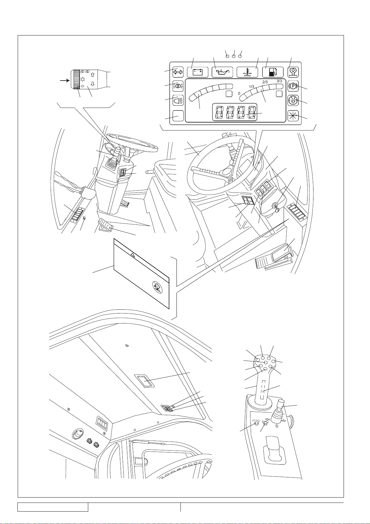
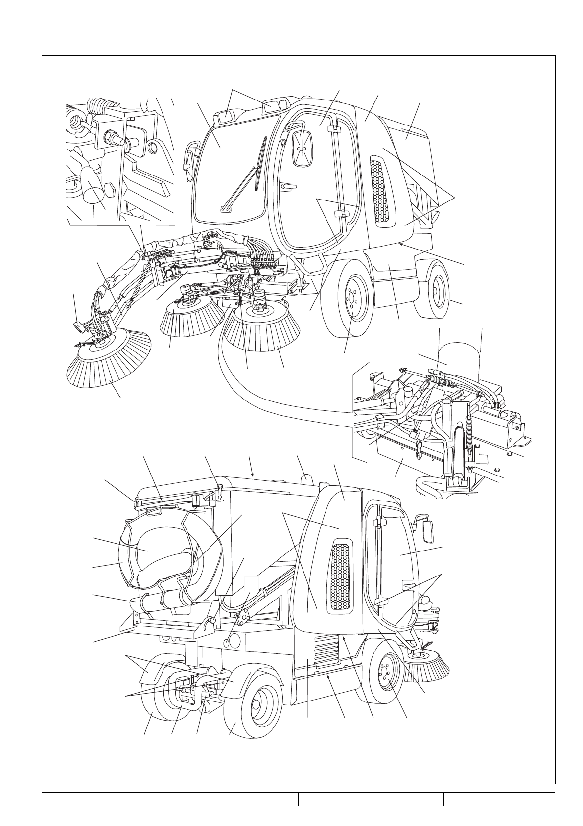
DESCRIPTION
Description of the control area
(See Fig. D)
1.
Meter and control panel
2.
Indicator light panel
3.
Lifted hopper warning light (red)
4.
High beam indicator light
5.
Running light indicator light
6.
Turn signal indicator light
7.
Charged battery indicator light
8.
Engine oil pressure warning light
9.
Engine coolant high temperature warning light
10.
Low fuel warning light
11.
Glow plug pre-heating warning light
12.
Parking brake warning light
13.
Clogged engine air fi lter warning light
14.
Water-in-fuel warning light
15.
Fuel level indicator
16.
Engine coolant temperature indicator
17.
Display showing:
•
Working hours (when the ignition key is turned on the
fi rst position, before running the engine)
•
Engine speed (when the engine is running and the
charged battery warning light is off)
The display can also show the following acronyms:
•
F.OPE: it indicates that the fuel level indicator cable is
not connected
•
F.COr: it indicates that the fuel level indicator cable is
shorted
•
H.OPE: it indicates that the engine coolant temperature
indicator is not connected
•
H.COr: it indicates that the engine coolant temperature
18.
19.
20.
21.
22.
23.
24.
25.
26.
27.
28.
29.
30.
31.
32.
indicator is shorted
Left vent
Ceiling light: If pressed on the right or left side, it turns on.
In central position, it turns off.
Hazard warning light switch
Hopper lid opening/closing switch
3rd broom tilting switch
Right vent
Ignition key
3rd broom rotation direction selector
Drive pedal
Dust control system water pump switch:
•
When the switch is turned to the fi rst position, the
nozzles sprinkle a medium quantity of water
•
When the switch is turned to the second position, the
nozzles sprinkle the maximum quantity of water
Steering wheel
Side brooms (fi rst position) and 3rd broom (second
position) switch
Suction fan/optional equipment switch
Brake pedal
Windscreen wiper fl uid tank
Windscreen wiper switch
33.
34.
35.
36.
37.
38.
39.
40.
41.
42.
43.
44.
45.
46.
47.
48.
49.
50.
51.
52.
53.
54.
In 0 position: windscreen wiper stopped
•
In 1 position: windscreen wiper moving
•
In 2 position (with spring-return): windscreen washer jet
•
3rd broom arm extension shifting switch (with springreturn)
Combination switch, having the following functions:
Headlights off, with mark (35b) at the symbol O
•
Running lights on, with mark (35b) at the symbol
•
•
Low beam on, with mark (35b) at the symbol
•
High beam on, with mark (35b) at the symbol and
lowered lever (35a)
•
High beam temporary on, lifting the lever (35a)
•
Right turn signal on, bringing the lever (35a) forward
•
Left turn signal on, bringing the lever (35a) backward
•
Horn activation, pushing the lever (35a) in the direction
shown by the arrow (35c)
Suction inlet, brooms, hopper joystick
Suction inlet and side broom lowering push-button
Suction inlet and side broom lifting push-button
Hopper return push-button
Hopper dumping push-button
Suction inlet and side broom left shifting push-button
Suction inlet and side broom right shifting push-button
Hopper lifting push-button
Hopper lowering push-button
Safety push-button (press and hold it to activate the other
push-buttons on the joystick)
3rd broom joystick, to activate the following functions (after
pressing the 3rd broom switch):
•
Forward: 3rd broom lowering
•
Backward: 3rd broom lifting
•
Right side: arm to the right side
•
Left side: arm to the left side
Skirt lifting push-button
Skirt lowering push-button
Full water tanks warning light (green)
Full water sub-tank warning light (yellow)
Empty water tanks warning light (red) (the pumps stop
automatically)
3rd broom working light switch
Closed hopper lid warning light
Warning decal
8
33015124(3)2008-02 RS 1300
Page 31

INSTRUCTIONS FOR USE
ENGLISH
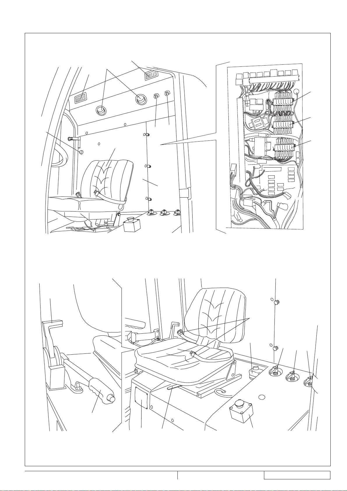
(See Fig. E)
1.
Serial number plate/technical data/conformity certifi cation
2.
Cab vents
3.
Upper fuse box
4.
Cab air recirculation vents
5.
Climate control knob
6.
Cab air fl ow control knob
7.
Brake fl uid tank
8.
Centre fuse box
9.
Lower fuse box
10.
Dust control system nozzle tap:
•
Suction hose (from suction inlet to hopper)
•
11.
12.
13.
14.
15.
16.
17.
18.
19.
20.
(*) Optional for some countries.
Rear suction pipe (*)
Side broom dust control system nozzle tap
3rd broom dust control system nozzle tap
Parking brake lever
Driver’s seat
Cab heater control knob
Diesel engine throttle lever
Driver’s seat forward/backward adjustment lever
Emergency stop mushroom-head push-button (optional)
Electrical component protection panel
Driver’s seat safety belt
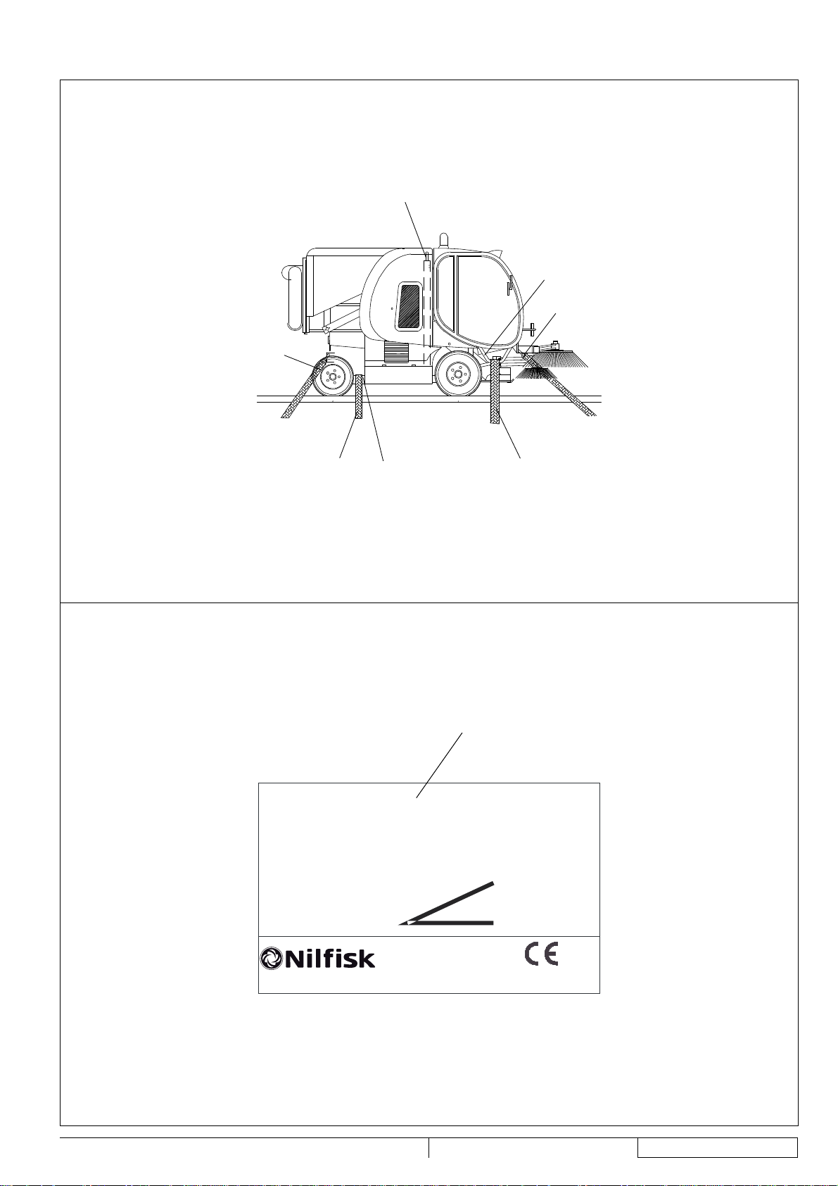
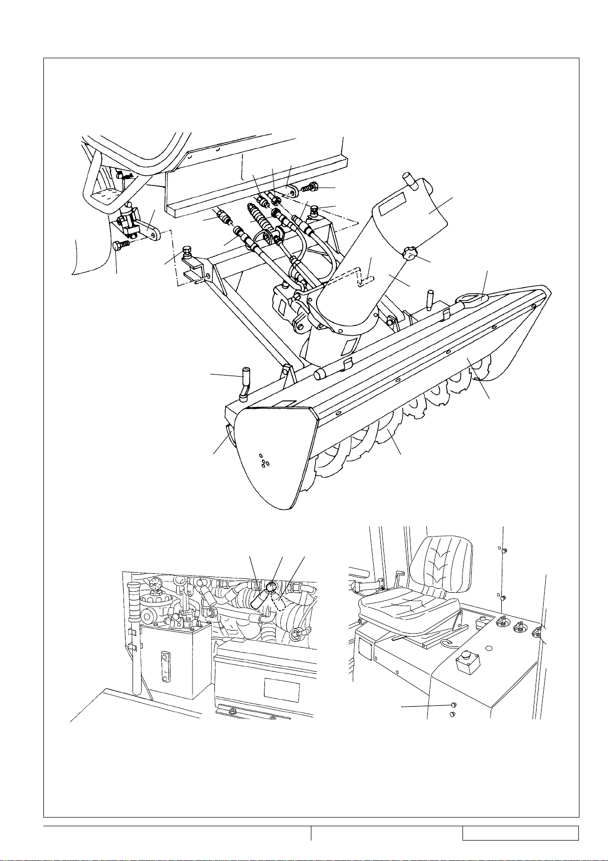
Outside view
(See Fig. F)
1.
Lifted and dumped hopper
2.
Lifted hopper support rods (not applied)
3.
Lifted hopper support rods (applied)
4.
Lifted hopper support rod fasteners (not applied)
5.
Suction hose gasket
6.
Suction hose (from suction inlet to hopper)
7.
Hopper front suction hole cover
8.
Cab climate control condenser
9.
Hydraulic system oil cooler
10.
Fuel tank fi ller neck
11.
Engine compartment panel
12.
Inlet air breather fi lter
13.
Suction fan compartment
14.
Debris defl ector
15.
Dust and debris suction fi lter
16.
Suction fi lter fasteners
17.
Hopper lid (open) support rod
18.
Hopper lid support rod housing
19.
Suction sealing gasket
20.
Hopper support rod housing
21.
High-pressure washing system hose with reel (*)
22.
High-pressure water quick coupling (*)
23.
Rear suction pipe dust control system nozzles tap
24.
Dust control system sub-tank
25.
Engine air fi lter
26.
Hopper water drain hose
27.
Hopper manual lifting hand pump lever
28.
Dust control system main tank
29.
Dust control system water supply hose
30.
Dust control system main tank plug
31.
Hydraulic system oil drain fi lter
32.
Hopper manual lifting hand pump
33.
Diesel engine (for a description of the diesel engine
components, refer to the relevant Manual)
34.
Battery
35.
Hydraulic system oil level indicator
36.
Hydraulic system oil tank
37.
Front wheel lifting bracket
38.
Bracket mounting knobs
39.
High-pressure water gun (*)
40.
Dust control system main tank fl oat
41.
Machine lifting hooks (to be used only when the hopper is
empty)
42.
Dust control system water level indicator
43.
Engine coolant tank
44.
High-pressure water gun sprinkler nozzle
45.
Fuel fi lter
46.
Engine air pre-fi lter
(*) Optional for some countries.
RS 1300 33015124(3)2008-02
9
Page 32

ENGLISH
INSTRUCTIONS FOR USE
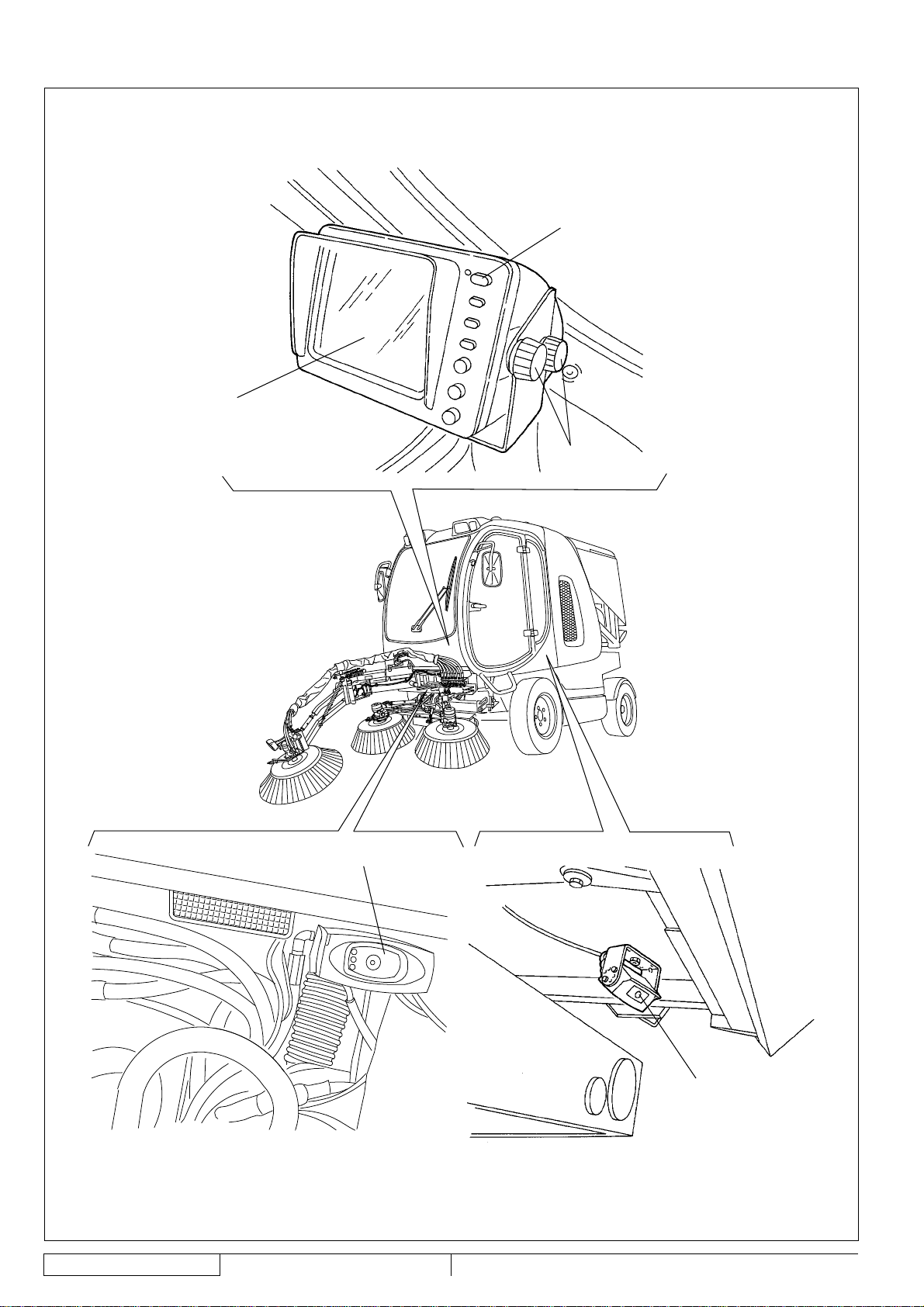
(See Fig. G)
1.
Cab
2.
Headlights
3.
3rd broom light
4.
Cab left door
5.
3rd broom arm safety pin for machine transfer
6.
Hopper
7.
Rear fenders
8.
Rear bumper bar
9.
Left side upper lid
10.
Right lid fasteners
11.
Left side lower lid
12.
Lid fastener
13.
Rear steering wheels
14.
Left under-cab lid
15.
Lid mounting screws
16.
Front driving wheels (fi xed)
17.
Suction inlet
18.
Front towing hook
19.
Left broom
20.
Right side broom
21.
3rd broom (*)
22.
3rd broom arm extension (*)
23.
3rd broom arm (*)
24.
Suction hose (from suction inlet to hopper)
25.
Front skirt
26.
Inlet air breather fi lter hood fasteners
27.
Inlet air breather fi lter hood
28.
Right side upper lid
29.
Right lid fasteners
30.
Cab right door
31.
Right under-cab lid
32.
Lid mounting screws
33.
Machine serial number
34.
Right side lower lid
35.
Lid fastener
36.
Rear steering axle
37.
Rear suction pipe support arm (engaged)
38.
Rear suction pipe cover
39.
Lighting and signalling system
40.
Rear shoote side mounting knob
41.
Rear dumping shoote (open)
42.
Rear suction pipe fastener
43.
Rear suction pipe (optional)
44.
Hopper door
45.
Rear towing hooks
46.
Suction inlet light
47.
Flashing light
(*) Optional for some countries.
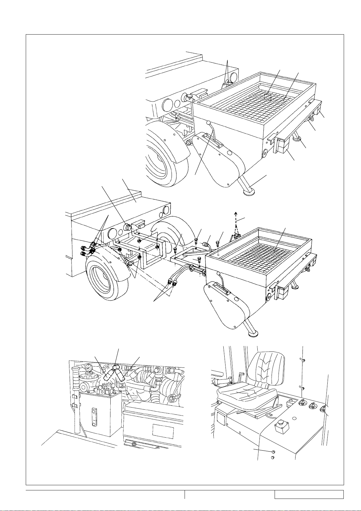
Salt spreader description (optional)
(See Fig. AU)
1.
Salt fl ow control lever
2.
Salt loading compartment
3.
Tail lights
4.
Adjustable feet, when the equipment is not installed to the
sweeper
5.
Lifting hook
6.
Junction box
7.
Technical data plate
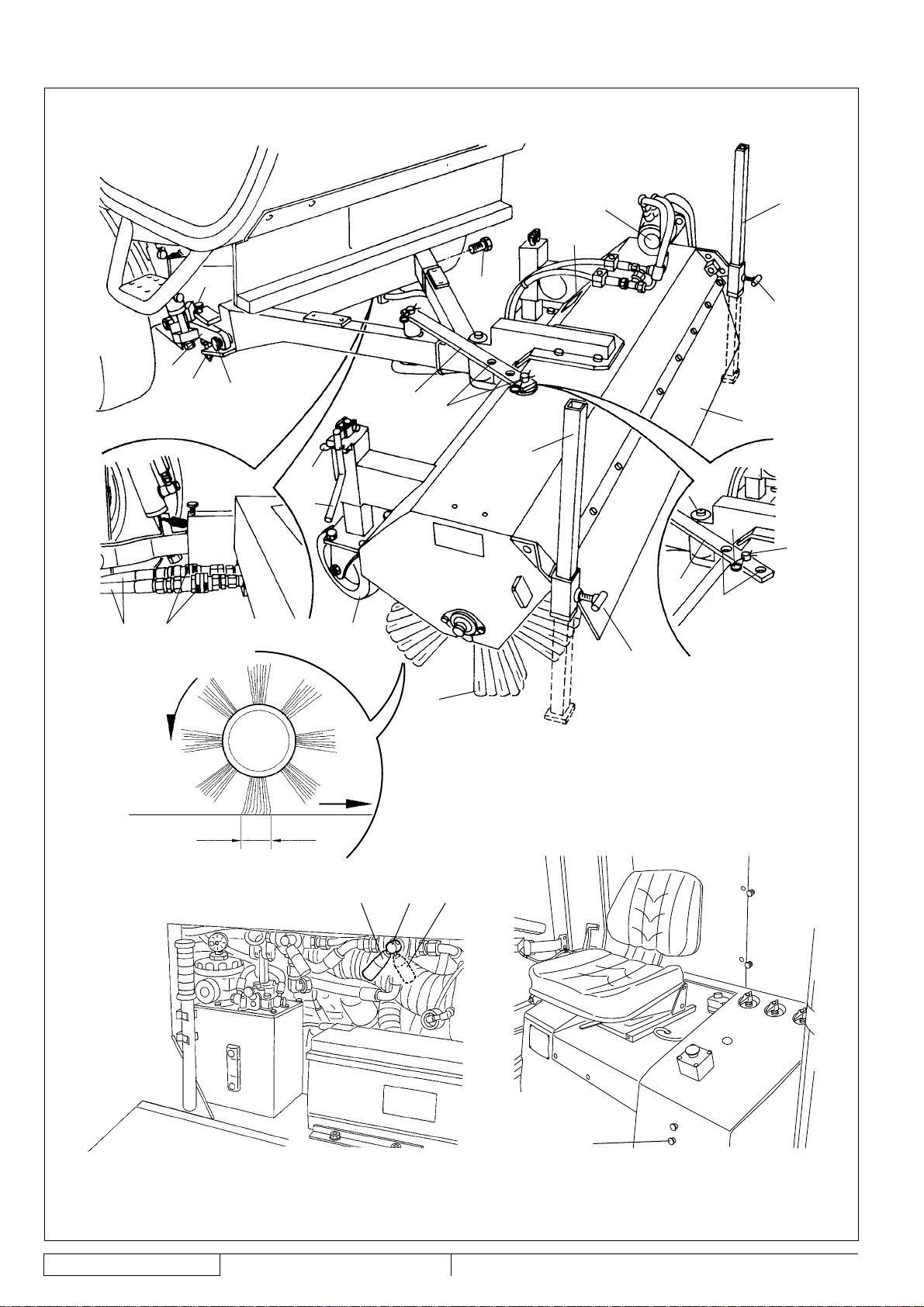
Snow brush description (optional)
(See Fig. AV)
1.
Quick coupling for connecting the hydraulic pipes to the
sweeper
2.
Sweeper hydraulic pipes, specifi c for the snow brush
3.
Technical data plate
4.
Hydraulic motor
5.
Adjustable feet, when the equipment is not installed to the
sweeper
6.
Adjustable feet mounting knob
7.
Front skirt
8.
Brush tilting positioning pin
9.
Brush tilting positioning pin clip
10.
Cylindrical brush
11.
Equipment support wheel
12.
Wheel lifting/lowering winch
13.
Winch mounting pin
14.
Equipment mounting screws
15.
Lower equipment height adjusting screw
16.
Upper equipment height adjusting screw
17.
Snow brush tilting positioning rod
18.
Positioning holes
19.
Suction inlet/equipment anchor arm
Snow cutter description (optional)
(See Fig. AW)
1.
Quick couplings for connecting the sweeper hydraulic
pipes with the equipment
2.
Quick coupling for connecting the equipment to the
sweeper hydraulic pipe, also used for the suction inlet
3.
Sweeper hydraulic pipes, specifi c for the snow brush
4.
Sweeper hydraulic pipes, also used for the suction inlet
5.
Discharge baffl e plate
6.
Baffl e plate mounting knobs
7.
Snow discharge pipe
8.
Snow cutter cleaning tool
9.
Skirt
10.
Cutter
11.
Sliding block
12.
Sliding block height adjustment winch
13.
Equipment mounting screw
14.
Equipment height adjusting screw
15.
Suction inlet/equipment anchor arm
16.
Discharge pipe adjustment winch
Camera kit description (optional)
(See Fig. AX)
1.
Display
2.
ON/OFF switch
3.
Video adjustment knobs
4.
Front camera
5.
Rear camera
10
33015124(3)2008-02 RS 1300
Page 33

INSTRUCTIONS FOR USE
ENGLISH
TECHNICAL DATA
Dimensions and weights Values
Machine length (broom bristles included) 155.1 in (3,940 mm)
Machine length with 3rd broom (broom bristles included) 174.0 in (4,420 mm)
Machine length with snow brush 155.5 in (3,950 mm)
Salt spreader equipment length 22.0 in (560 mm)
Machine width (broom bristles included) 57.1 in (1,450 mm)
Snow brush width 59.0 in (1,500 mm)
Distance between front and rear wheels 71.6 in (1,820 mm)
Front wheel base 44.9 in (1,140 mm)
Rear wheel base 42.3 in (1,075 mm)
Machine height 85.8 in (2,180 mm)
Minimum distance from the ground (skirts not included) 3.5 in (90 mm)
Maximum front working angle 15°
Maximum dumping height 63.0 in (1,600 mm)
Front tires 195 R 14C 106/104N (8 PR)
Rear tires 23x8.50-12 (10 PR)
Tire pressure 72.5 psi (5 Bar)
Side broom diameter 25.6 in (650 mm)
Total machine weight, in running condition (without operator) 6,063 lb (2,750 kg)
Total machine weight, in running condition with snow brush (without operator) 6,063 lb (2,750 kg)
3rd broom weight 331.0 lb (150 kg)
Salt spreader equipment weight 287.0 lb (130 kg)
Total mass 8,818 lb (4,000 kg)
Performance data Values
Maximum forward speed (for transport only) 13.7 mph (22 km/h)
Maximum working speed 7.4 mph (12 km/h)
Maximum reverse speed 5.0 mph (8 km/h)
Gradeability at full load 24% (30% optional)
Minimum inner turning radius 90.5 in (2,300 mm)
Maximum side broom speed 77 rpm
Collection system Suction
Cleaning width with 2/3 brooms 63.0/82.7 in (1,600/2,100 mm)
Filtering system Metallic net
Sound pressure level at workstation (ISO/EN3744) at maximum working speed 79 dB(A)
Certifi ed sound power (2000/14/EC) at maximum working speed 110 dB(A)
Hopper capacity 343.4 USgal (1,300 litres)
Hopper maximum load 2,425 lb (1,100 kg)
Dust control By water
Dust control system tank total capacity (no. 2) 66.0 USgal (250 litres)
Tail lights Road type
Transmission Hydrostatic servoassisted
Steering system On the rear axle, power assisted
Brake Hydraulic
Parking brake Mechanic
Controls Electrohydraulic
RS 1300 33015124(3)2008-02
11
Page 34

ENGLISH
HR 494 HT3 diesel engine data (*) Values
Make VM MOTORI
Type HR 494 HT3
Cylinders 4
Displacement 169.4 in
Maximum speed 2,300 rpm
Maximum working speed 2,050 rpm
Maximum power 73.7 Hp (55 kW)
Maximum torque 170 lb·ft (230 N·m)
Emissions CE 99/96-Euro3 CE97/68-Stage 2
Idle speed 1,200 rpm
Engine coolant 50% of AGIP antifreeze and 50% of water
Antifreeze type AGIP Antifreeze Extra (**)
Engine oil type AGIP Sigma Turbo 15W40 (***)
Engine oil pan capacity 13.0 lb (5.8 kg)
INSTRUCTIONS FOR USE
3
(2,776 cm3)
(*) For other diesel engine data/values, see the relevant Manual.
(**) See the coolant technical data and reference data tables below.
(**) See the engine oil technical data and reference data tables below.
DT04 TE2 diesel engine data (*) (for American market only) Values
Make VM MOTORI
Type DT04 TE2
Cylinders 4
Displacement 169.4 in
Maximum speed 2,300 rpm
Maximum working speed 2,050 rpm
Maximum power 80.5 Hp (60 kW)
Maximum torque 214 lb·ft (290 N·m)
Emissions EPA-97/68/EC Stage 2
Idle speed 1,200 rpm
Engine coolant 50% of AGIP antifreeze and 50% of water
Antifreeze type AGIP Antifreeze Extra (**)
Engine oil type AGIP Sigma Turbo 15W40 (***)
Engine oil pan capacity 13.0 lb (5.8 kg)
3
(2,776 cm3)
(*) For other diesel engine data/values, see the relevant Manual.
(**) See the coolant technical data and reference data tables below.
(***) See the engine oil technical data and reference data tables below.
AGIP ANTIFREEZE EXTRA SPECIFICATIONS Approvals and specifi cations
Boiling point °F (°C) 338 (170) CUNA NC 956-16 97
Boiling point in solution with 50% water °F (°C) 230 (110) FF.SS cat. 002/132
Freezing point in solution with 50% water °F (°C) -36.4 (-38) ASTM D 1384
Color / Turquoise blue
Density at +59°F (+15°C) kg/l 1.13
12
33015124(3)2008-02 RS 1300
Page 35

INSTRUCTIONS FOR USE
ENGLISH
AGIP SIGMA TURBO 15W40 SPECIFICATIONS Approvals and specifi cations
SAE QUALITY / 15W40 ACEA E3-96
Viscosity at +212°F (+100°C) mm
Viscosity at +104°F (+40°C) mm
Viscosity at +5°F (-15°C) mm
2
/s 13.7 API Service CG-4/SG
2
/s 100 CCMC D5, PD-2
2
/s 3,300 US Department of the Army MIL-L-2104 E
Viscosity index / 138 US Department of the Army MIL-L-46152 E
Flash point COC °F (°C) 446 (230) MACK EO-L
Pour point °F (°C) -16.6 (-27) MAN M 3275
Density at +59°F (+15°C) kg/l 0.885 Mercedes Benz 228.3
VOLVO VDS2
MTU typ 2
Refuelling data Values
Fuel tank capacity 19.8 USgal (75 litres)
Hydraulic system oil tank capacity 11.9 USgal (45 litres)
Electrical system data Values
System voltage 12 V
Starting battery 12 V – 100 Ah
Hydraulic system data Values
Maximum drive system pressure 3,626 psi (250 Bar)
Suction fan system maximum pressure 3,046 psi (210 Bar)
Maximum accessory system pressure 3,046/1,885 psi (210/130 Bar)
Hydraulic system oil viscosity [at ambient temperatures above +50°F (+10°C)] (*) 46 cSt
Hydraulic system oil type AGIP Arnica 46 (**)
Brake fl uid type DOT4 (***)
(*) If the machine is to be used at ambient temperatures below +50°F (+10°C), the oil should be replaced with equivalent oil
having a viscosity of 32 cSt. For temperatures below +32°F (0°C), use oil with lower viscosity.
(**) See the hydraulic system oil technical data and reference data tables below.
(***) See the brake fl uid technical data and reference data tables below.
AGIP ARNICA SPECIFICATIONS 46 32 Approvals and specifi cations
Viscosity at +104°F (+40°C) mm
Viscosity at +212°F (100°C) mm
2
/s 45 32 ISO-L-HV
2
/s 7.97 6.40 ISO 11158
Viscosity index / 150 157 AFNOR NF E 48603 HV
Flash point COC °F (°C) 419 (215) 395.6 (202) AISE 127
Pour point °F (°C) -32.8 (-36) -32.8 (-36) A TOS Tab. P 002-0/I
Density at +59°F (+15°C) kg/l 0.87 0.865 BS 4231 HSE
CETOP RP 91 H HV
COMMERCIAL HYDRAULICS
Danieli Standard 0.000.001 (AGIP
ARNICA 22, 46, 68)
EATON VICKERS I-286-S3
EATON VICKERS M-2950
DIN 51524 t.3 HVLP
LAMB LANDIS-CINCINNATI P68, P69, P70
LINDE
PARKER HANNIFIN (DENISON) HF-0
REXROTH RE 90220-1/11.02
SAUER-DANFOSS 520L0463
RS 1300 33015124(3)2008-02
13
Page 36

ENGLISH
DOT4 SPECIFICATIONS Approvals and specifi cations
Viscosity at -40°C (-40°F) mm
Viscosity at +212°F (+100°C) mm
Dry boiling point °F (°C) 509 (265) ISO 4925
Wet boiling point °F (°C) 338 (170) CUNA NC 956 DOT4
Density at +59°F (+15°C) kg/l 1.07
Color / Yellow
Climate control system data Values
Gas type Reclin 134a
Gas quantity 1.76 lb (0.8 kg)
Salt spreader system description (optional) (*) Values
Make - type Epoke - PM 1.4
Snow brush description (optional) (*) Values
Make - type Tuchel - ZKM
Snow cutter description (optional) (*) Values
Make - type Bittante - Single-stage
INSTRUCTIONS FOR USE
2
/s 1,300 SAE J 1703
2
/s 2.2 FMVSS 116 - DOT4&DOT3
Camera kit description (optional) (*) Values
Make - type IMEL - Car Vision System
(*) For other data/values of the optional equipment, see the relevant Manuals.
ENVIRONMENTAL CONDITIONS
In the environment where the machine operates, there must not be any danger of explosion.
–
To avoid inhaling exhaust gas, the machine must be used only where there is a proper ventilation.
–
The machine operates correctly (*) in the following environmental conditions:
–
Temperature: +14°F to +104°F (-10°C to +40°C)
•
Humidity: 30% to 95%
•
(*) When using the machine at ambient temperatures between +14°F and +32°F (-10°C and 0°C), the dust control system cannot
be used; moreover the water tanks and the dust control system itself must be empty.
14
33015124(3)2008-02 RS 1300
Page 37

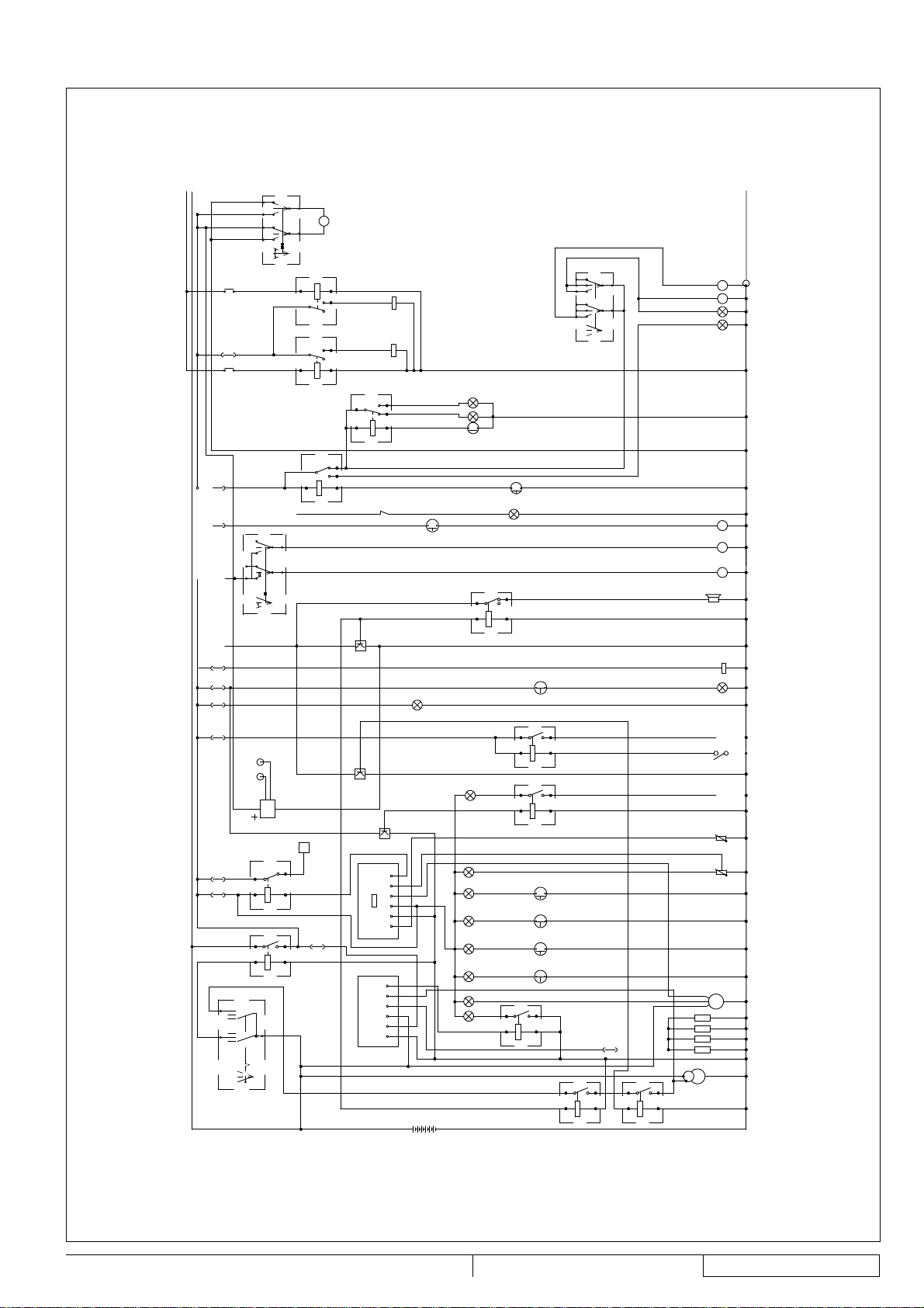
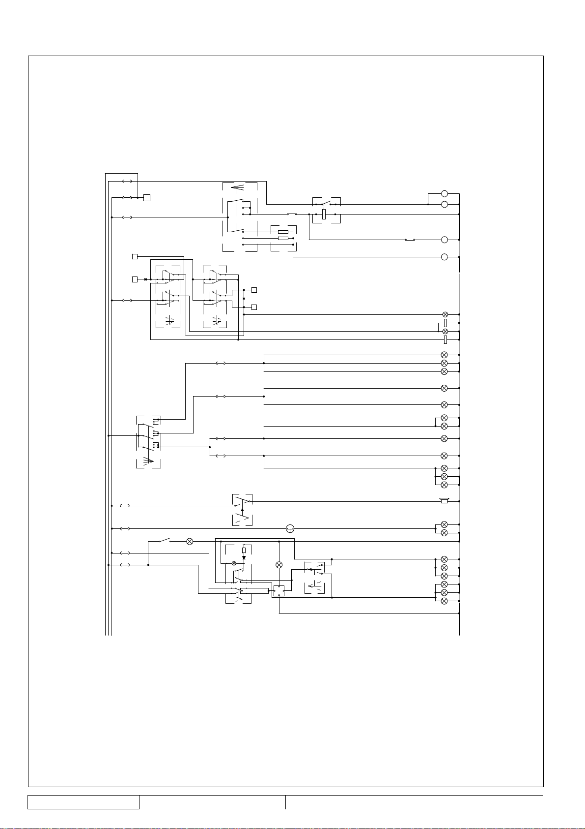
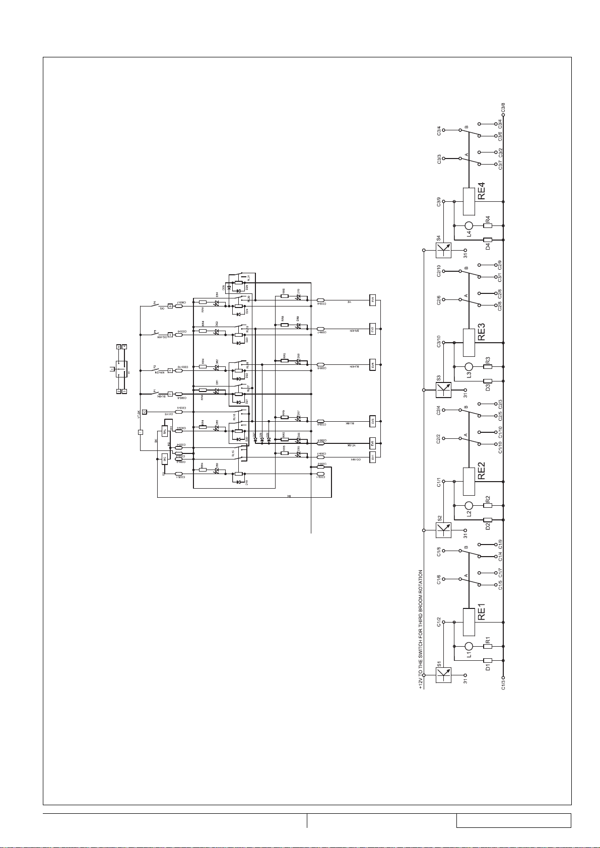
WIRING DIAGRAM
(See Fig. AR1 and AR2)
A Alternator
B 12 V battery
B1 Hydraulic system oil cooler fan bulb
C1 Engine start electromagnet
C2 Climate control system compressor (*)
C3 Ignition switch
C4 Windscreen wiper switch
C5 Water pump switch
C6 Hazard warning light switch
C7 Suction fan/optional equipment switch
C8 Broom switch
C10 Lid closing/opening actuator switch
C11 Brake light microswitch
C12 Hopper microswitch
C13 Engine oil bulb
C14 Engine coolant bulb
C16 Parking brake microswitch
C17 Clogged air fi lter pressure switch
C18 Water temperature transducer
C19 Fuel level fl oat
C20 3rd broom working light switch
C21 Climate control system blower switch (*)
C22 Cab light switch
CC1 Reverse gear buzzer
CK Glow plug control unit
D1 Combination switch
D02 6 A, 60 V diode
D03 6 A, 60 V diode
EG Fuel solenoid valve
EV Blower
EL1 Suction fan solenoid valve
EL2 Optional equipment solenoid valve
EV3 Skirt lifting solenoid valve
EV4 Skirt lowering solenoid valve
EVC1 Climate control system blower (*)
EVC2 Climate control system solenoid valve (*)
F1 Choke system fuse (7.5 A)
F2 Skirt solenoid valve fuse (10 A)
F3 Skirt push-button fuse (7.5 A)
F4 Optional equipment fuse (10 A)
F5 Blower fuse (20 A)
F6 Fuel solenoid valve fuse (7.5 A)
F7 Broom safety fuse (15 A)
F8 Water pump fuse (15 A)
F9 Climate control system blower fuse (20 A) (*)
F10 Climate control system fuse (15 A) (*)
F11 Windscreen wiper fuse (10 A)
F12 Flashing light fuse (7.5 A)
F13 Glow plug control unit fuse (7.5 A)
F14 Meter fuse (7.5 A)
F15 Reverse gear buzzer fuse (7.5 A)
INSTRUCTIONS FOR USE
F16 Open hopper/lid warning light fuse (7.5 A)
F17 Left side running light fuse (7.5 A)
F18 Right side running light fuse (7.5 A)
F19 Low beam fuse (10 A)
F20 High beam fuse (15 A)
F21 Brake light fuse (7.5 A)
F22 Horn fuse (7.5 A)
F23 Hazard warning lights/cab light fuse (10 A)
F24 Turn signal fuse (7.5 A)
F25 Glow plug fuse (80 A)
G1 Dust control system water level indicator
G2 Dust control system main tank fl oat
L1 Left front turn signal
L2 Left side turn signal
L3 Left rear turn signal
L4 Right front turn signal
L5 Right side turn signal
L6 Right rear turn signal
L4/6 Right side turn signals
L7 Left front running light
L8 Right rear running light
L9 Suction inlet light
L10 Right front running light
L11 Left rear running light
L12 Licence plate light
L13 Cab light
L14 Left brake light
L15 Right brake light
L16 Left low beam
L17 Right low beam
L18 Left high beam
L19 Right high beam
L20 Flashing light
M Starter
MB Skirt actuator
ML Windscreen washer system
MN Camera display (*)
MP1 Water pump motor
MP2 Water pump motor
MR Cab blower motor
MS Hopper lid actuator motor
MT Windscreen wiper motor
P Climate control system pressure switch
P2 Skirt lifting push-button
P3 Skirt lowering push-button
PR Reverse gear sensor
PX Engine start safety sensor
R1 General relay
R2 Broom safety relay
R3 Climate control system blower relay (*)
ENGLISH
RS 1300 33015124(3)2008-02
15
Page 38

ENGLISH
INSTRUCTIONS FOR USE
R4 Reverse gear sensor relay
R5 Turn signal intermittence relay
R6 Dust control system water pump relay
R7 Dust control system water level relay
R8 Skirt lifting relay
R9 Skirt closing relay
R10 Water-in-fuel warning light relay
R11 Glow plug warning light relay
R12 Choke system relay
RS Climate control system blower resistance (*)
RX Engine start safety relay
RY Engine start safety relay
S1 Glow plug warning light
S2 Battery warning light
S3 Engine oil warning light
S4 Engine coolant warning light
S5 Low fuel warning light
S6 Parking brake warning light
S7 Clogged air fi lter warning light
S8 Turn signal indicator light
S9 Hazard warning light indicator
S10 Running light indicator light
S11 High beam indicator light
S12 Dust control system low water warning light
S13 Lifted hopper warning light
S14 Water pump ON warning light
S15 Meter
S16 Water-in-fuel sensor
S17 Broom rotation warning light
S18 3rd broom working light
S19 Full dust control system main tank warning light
S20 Empty dust control system main tank warning light
S21 Optional equipment warning light
S22 Water-in-fuel warning light
T Horn
TA1 Water temperature transducer
TL1 Rear camera
TL2 Front camera
TM Climate control system control knob
K1/4 Glow plugs
3RD BROOM ARM WIRING DIAGRAM (*)
(See Fig. AS)
“A” 3rd broom relay board
“B” 3rd broom board wiring diagram (left and right)
C005 Input connector
C006 Output connector
D19/26 IN4007 diode
D27/29 6A60/P600K diode
D59 Rotation safety sensor input led
D60 Lifting safety sensor input led
D61 Lifting push-button input led
EV1 Rotation solenoid valve
EV2 Right shifting solenoid valve
EV3 Solenoid valve
P1 Broom lifting push-button
P2 Arm left shifting (rotation) push-button
P3 Arm right shifting (rotation) push-button
P4 Broom lowering push-button
RL20 Broom lowering relay
RL21 Broom lowering relay
RR4/RR5 Multi-resistance
(*) Optional for some countries.
Color code
BK Black
BU Light blue
BN Brown
GN Green
GY Grey
OG Orange
PK Pink
RD Red
VT Violet
WH White
16
33015124(3)2008-02 RS 1300
Page 39

INSTRUCTIONS FOR USE
ENGLISH
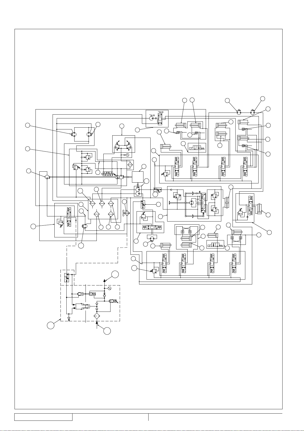
Hydraulic diagram
(See Fig. AT)
Hydraulic system oil tank
81.
Drain fi lter
82.
Suction fi lter
83.
Drive system pump
84.
Diesel engine
85.
Left drive system motor
86.
Accessory system control valve assembly
87.
Front skirt lifting cylinder
88.
Hopper lifting cylinder
89.
Hand pump
90.
Side broom motor
91.
Right drive system motor
92.
Hydraulic system oil cooler
93.
Solenoid valve
94.
Suction inlet side shifting cylinder
95.
Suction inlet lifting cylinder
96.
Check valve
97.
Hopper dumping cylinder
98.
Power steering
99.
Flow separator (priority valve)
100.
Accessory and 3rd broom pump
101.
Suction fan pump
102.
Suction fan control valve assembly
103.
Front skirt control valve assembly
104.
Suction fan motor
105.
3rd broom control valve assembly (*)
106.
3rd broom tilting cylinder (*)
107.
3rd broom second shifting cylinder (*)
108.
Check valve (*)
109.
3rd broom lifting cylinder (*)
110.
3rd broom fi rst shifting cylinder (*)
111.
3rd broom motor control valve assembly (*)
112.
3rd broom motor (*)
113.
Power steering cylinder
114.
Drive pedal assist
115.
Suction fi lter
116.
Suction fi lter
117.
Suction fi lter
118.
Priority valve (*)
119.
High-pressure washing system pump (*)
120.
Water suction (*)
121.
Water outlet (*)
122.
(*) Optional for some countries.
ELECTRICAL FUSES
In the left compartment of the cab rear wall, there is an
electrical cabinet, which contains three fuse boxes (3, 8 and 9,
Fig. E). Each fuse box is equipped with a transparent plastic
cover and contains the following fuses:
Fuse box (3, Fig. E)
Choke system fuse (7.5 A)
1.
Skirt solenoid valve fuse (10 A)
2.
Skirt push-button fuse (7.5 A)
3.
Optional equipment fuse (10 A)
4.
Blower fuse (20 A)
5.
Fuel solenoid valve fuse (7.5 A)
6.
Broom safety fuse (15 A)
7.
Water pump fuse (15 A)
8.
Fuse box (8, Fig. E)
Climate control system blower fuse (20 A) (*)
1.
Climate control system fuse (15 A) (*)
2.
Windscreen wiper fuse (10 A)
3.
Flashing light fuse (7.5 A)
4.
Glow plug control unit fuse (7.5 A)
5.
Meter fuse (7.5 A)
6.
Reverse gear buzzer fuse (7.5 A)
7.
Open hopper/lid warning light fuse (7.5 A)
8.
Fuse box (9, Fig. E)
Left side running light fuse (7.5 A)
1.
Right side running light fuse (7.5 A)
2.
Low beam fuse (10 A)
3.
High beam fuse (15 A)
4.
Brake light fuse (7.5 A)
5.
Horn fuse (7.5 A)
6.
Hazard warning lights/cab light fuse (10 A)
7.
Turn signal fuse (7.5 A)
8.
Glow plug fuse (80 A)
9.
(*) Optional for some countries.
ACCESSORIES/OPTIONS
In addition to the standard components, the machine can be
equipped with the following accessories/options, according to
the machine specifi c use:
3rd broom (*)(**)
–
Brooms with harder and softer bristles
–
Salt spreader (*)(**)
–
Snow brush (*)(**)
–
Snow cutter (*) (**)
–
Camera kit (*)
–
High-pressure washing system (*)(**)
–
Audio unit (*) (**)
–
(*) Optional for some countries.
(**) In order to use these accessories, the sweeper must be
equipped with the appropriate fi ttings.
RS 1300 33015124(3)2008-02
17
Page 40

ENGLISH
INSTRUCTIONS FOR USE
USE
WARNING!
On some points of the machine there are some adhesive plates indicating:
DANGER
−
WARNING
−
CAUTION
−
CONSULTATION
−
While reading this Manual, the operator must pay particular attention to the symbols shown.
Do not cover these plates for any reason and immediately replace them if they are damaged.
GENERAL CAUTIONS
This machine is designed as a high performance, high capacity sweeper that can clean in tight and congested areas.
By design this means a narrow wheel base with tight steering capability.
These design requirements can under certain conditions create instability during machine operation.
Instability can be caused by a combination of machine travel speed, abrupt maneuvering, operation on an incline, low tire pressure,
weight in the hopper and or raised hopper.
For this reason the machine must be driven by a qualifi ed operator who must be properly instructed on how to use it and be aware
of the potential risks.
The following are situations known to cause instability in the machine and care should be taken by the operator to assure safe
operation:
Lifting the hopper on an incline
–
Maneuvering the machine with the hopper lifted
–
Abrupt steering
–
Maneuvering with speed, on a slope and/or with weight in the hopper
–
Low tire pressure
–
Inside the cab there is a decal (19, Fig. E) that warns the operator of the risk of instability and provides information on activities to
avoid to prevent machine instability (see picture).
BEFORE START-UP
If necessary, open the right upper lid (28, Fig. G) by releasing the fasteners (29) with the supplied key, and refuel the machine
1.
through the fi ller neck (10, Fig. F).
CAUTION!
Do not fi ll the fuel tank to the top, but leave at least 1.6 in (4 cm) from the fi ller neck to allow the fuel to expand.
Check the dust control system water level through the indicator (42, Fig. F). If necessary, supply water according to the
2.
following procedure:
Disengage the fasteners (10, Fig. G) with the supplied key, then open the left lid (9).
•
Pour the water in the tanks through the plug (30, Fig. F), or the hose (29).
•
Close the plug (30), or roll up the hose (29) and place it back in its housing.
•
Close the lid (9, Fig. G) and secure it with the fasteners (10) by using the supplied key.
•
Check that there are no open lids/hoods and that the machine is in normal operating conditions.
3.
18
33015124(3)2008-02 RS 1300
Page 41

INSTRUCTIONS FOR USE
ENGLISH
DIESEL ENGINE START AND STOP
Diesel engine start
1.
Sit on the driver’s seat (14, Fig. E) and check that the parking brake (13) is engaged.
2.
With the lever (17, Fig. E), adjust the seat for a comfortable position.
3.
Fasten the seat belts.
CAUTION!
For the operator’s safety, the seat belts must always be fastened.
4.
Turn the engine throttle lever (16, Fig. E) to idle.
5.
Check that the brooms are lifted, otherwise keep into consideration that, when starting the engine, broom immediate rotation
can cause damages.
6.
Sit on the driver’s seat (14, Fig. E), insert the ignition key (24, Fig. D), turn it clockwise and hold it in the fi rst position. The
following warning lights and indicators turn on:
•
Diesel engine glow plug pre-heating warning light (11, Fig. D)
•
Charged battery indicator light (7, Fig. D)
•
Engine oil pressure warning light (8, Fig. D)
•
Parking brake warning light (12, Fig. D)
When the glow plug pre-heating warning light (11, Fig. D) turns off, turn the ignition key clockwise, to the end of stroke, and
then release it when the diesel engine starts.
CAUTION!
When starting the engine, do not keep the ignition key in cranking position too long (maximum 15 seconds) to
avoid damaging the starter. If the engine does not start, wait a minute before trying again.
Before trying to start the engine again, turn the ignition key counterclockwise, to the initial position.
If the engine does not start after two attempts, do not persist, ask for help from the person responsible for the
machine.
CAUTION!
When starting the engine with the ignition key (24, Fig. D) do not press the drive pedal (26), because the machine
is equipped with a safety system that does not allow for engine start-up in this condition.
Make sure that all the warning lights are off when the engine is running.
7.
With the throttle lever (16, Fig. E) in an intermediate position, let the engine run for a few minutes to allow it to warm up,
8.
especially when the air temperature is low.
Diesel engine stop
Turn the engine throttle lever (16, Fig. E) to idle, and hold it in this position for a few minutes to let the system stabilize.
9.
Turn the ignition key (24, Fig. D) counterclockwise, to the end of stroke, then remove it.
10.
Engage the parking brake with the lever (13, Fig. E).
11.
RS 1300 33015124(3)2008-02
19
Page 42

ENGLISH
INSTRUCTIONS FOR USE
STARTING AND STOPPING THE MACHINE
The machine can be started and set to:
–
Transport mode
–
Working mode
The relevant procedures are shown below.
WARNING!
When steering, avoid abrupt direction changes, pay careful attention and drive the machine at slow speed,
especially when the hopper is full or when operating on inclines.
CAUTION!
Before operating the machine, check that the tire pressure is correct (72.5 psi [5 bar]) and, if necessary, adjust it.
Setting the machine to transport mode
To transport the machine (without sweeping), it is necessary to set the transfer mode according to the following procedure:
Check that the parking brake (13, Fig. E) is engaged.
1.
Start the engine as shown in the previous paragraph.
2.
Check that the hopper (6, Fig. G) is lowered and that the warning light (3, Fig. D) is off.
3.
Check that the suction fan is off; see the switch (30, Fig. D).
4.
Lift the suction inlet and side brooms by pressing the push-button (38, Fig. D).
5.
Lift the 3rd broom arm (23, Fig. G) by pushing the joystick (46, Fig. D) rearward.
6.
Press and hold the spring-return switch (34, Fig. D) and shift the 3rd broom arm extension (22, Fig. G) to the right until the end
7.
of stroke (the shifting operation will stop automatically).
Shift the 3rd broom arm (23, Fig. G) to closed position by pushing the joystick (46, Fig. D) to the left.
8.
The shifting operation will stop automatically when the end of stroke is reached.
WARNING!
It is possible to shift to the left or to the right the 3rd broom arm (23, Fig. G) safely, only when the arm extension
(22) is to the left or right end of stroke.
In this situation the arm shifting is limited by proper safety devices.
Otherwise, an excessive shifting can damage the machine or affect its stability.
It is therefore advisable to bring always the 3rd broom arm extension (22, Fig. G) to the left or right end of
stroke.
WARNING!
It is possible to bring the 3rd broom arm (23, Fig. G) to closed position, only when the arm extension (22) is to
the right end of stroke.
Stop the 3rd broom and side broom rotation with the switch (29, Fig. D).
9.
Get out of the machine and bring the 3rd broom safety pin from the position (2, Fig. H) (disengaged) to the position (1)
10.
(engaged), by pulling and turning the relevant lever.
Disengage the parking brake with the lever (13, Fig. E).
11.
Gradually bring forward the engine throttle lever (16, Fig. E) and set the engine speed on the display (17, Fig. D) to 2,600 rpm.
12.
Start to transport the machine, by keeping the hands on the steering wheel (28, Fig. D) and gradually pressing the pedal (26),
13.
on the front side to move forward and on the rear side to move backward.
The drive speed can be adjusted from zero to maximum speed by increasing the pressure on the pedal.
Stopping the machine in transport mode
To stop the machine release the pedal (26, Fig. D).
14.
To stop the machine quickly, press also the brake pedal (31).
Turn the engine throttle lever (16, Fig. E) to idle, and hold it in this position for a few minutes to let the system stabilize.
15.
Turn off the engine, by turning the ignition key (24, Fig. D) counterclockwise, to the end of stroke, then remove it.
16.
Engage the parking brake with the lever (13, Fig. E).
17.
20
33015124(3)2008-02 RS 1300
Page 43

INSTRUCTIONS FOR USE
Setting the machine to working mode
Set the machine to working mode according to the following procedure:
Start the engine as shown in the relevant paragraph.
18.
Check that the hopper (6, Fig. G) is lowered and that the warning light (3, Fig. D) is off.
19.
Bring the 3rd broom safety pin from the position (1, Fig. H) (engaged) to the position (2) (disengaged), by pulling and turning
20.
the relevant lever.
Start the side broom rotation by turning the switch (29, Fig. D) to the fi rst position, and the 3rd broom rotation by turning the
21.
switch (29) to the second position.
Shift the 3rd broom arm (23, Fig. G) from closed position to opened position by pushing the joystick (46, Fig. D) to the right.
22.
The shifting operation will stop automatically when the end of stroke is reached.
WARNING!
It is possible to shift to the left or to the right the 3rd broom arm (23, Fig. G) safely, only when the arm extension
(22) is to the left or right end of stroke.
In this situation the arm shifting is limited by proper safety devices.
Otherwise, an excessive shifting can damage the machine or affect its stability.
It is therefore advisable to bring always the 3rd broom arm extension (22, Fig. G) to the left or right end of
stroke.
Prepare the machine for cleaning to the right or to the left according to the following procedure.
23.
For cleaning to the right:
With the spring-return switch (34, Fig. D), check that the 3rd broom arm extension (22, Fig. G) is to the right end of stroke.
•
Otherwise bring it to the above-mentioned position by pressing and holding the switch (34, Fig. D).
Select the counter-clockwise rotation of the 3rd broom with the selector (25, Fig. D).
•
Adjust the 3rd broom tilting angle in order to push the debris towards the suction inlet. To obtain the correct tilting, use the
•
switch (22, Fig. D) and set the broom (1, Fig. AK) as shown in the fi gure (the fi gure shows the 3rd broom as viewed from
the driver’s seat).
For cleaning to the left:
Press and hold the spring-return switch (34, Fig. D) to shift the 3rd broom arm extension (22, Fig. G) to the left end of
•
stroke. The shifting operation will stop automatically when the end of stroke is reached.
Select the clockwise rotation of the 3rd broom with the selector (25, Fig. D).
•
Adjust the 3rd broom tilting angle in order to push the debris towards the suction inlet. To obtain the correct tilting, use the
•
switch (22, Fig. D) and set the broom (2, Fig. AK) as shown in the fi gure (the fi gure shows the 3rd broom as viewed from
the driver’s seat).
Gradually bring forward the engine throttle lever (16, Fig. E) and set the engine speed on the display (17, Fig. D) to the
24.
following value:
Minimum 1,800 rpm
•
Maximum 2,000 rpm
•
ENGLISH
CAUTION!
If the engine speed exceeds 2,050 rpm in working mode, a safety system stops the broom rotation.
Turn on the suction fan with the switch (30, Fig. D).
25.
Lower the suction inlet and side brooms by pressing the push-button (37, Fig. D).
26.
Lower the 3rd broom by pushing the joystick (46, Fig. D) forward. If it is necessary to lift the broom while working, push the
27.
joystick (46) rearward.
Check and, if necessary, top up the dust control system water tanks, and check which one of the three warning lights (49, 50,
28.
51, Fig. D) stays on:
Full water tanks warning light (green) (49, Fig. D)
•
Full water sub-tank warning light (yellow) (50, Fig. D)
•
Empty water tanks warning light (red) (51, Fig. D). When this warning light turns on, the pumps stop automatically.
•
If necessary, open the dust control system taps (10, 11, 12, Fig. E), considering the following:
29.
Suction pipe dust control system nozzle tap (10, Fig. E): Open it always, except when the fl oor to be cleaned is wet. This
•
tap sends water also to the rear pipe dust control system nozzle (optional).
Side broom dust control system nozzle tap (11, Fig. E): Open it when the fl oor is dry and dusty.
•
3rd broom dust control system nozzle tap (12, Fig. E): Open it when the fl oor is dry and dusty.
•
RS 1300 33015124(3)2008-02
21
Page 44

ENGLISH
Turn on the dust control system water pump with the switch (27, Fig. D) according to the following procedure:
30.
When the switch is turned to the fi rst position, the nozzles sprinkle a medium quantity of water
•
(Use it when there is little dust)
When the switch is turned to the second position, the nozzles sprinkle the maximum quantity of water
•
(Use it when there is a lot of dust)
Disengage the parking brake with the lever (13, Fig. E).
31.
Start sweeping, by keeping the hands on the steering wheel (28, Fig. D) and gradually pressing the pedal (26), on the front
32.
side to move forward and on the rear side to move backward.
The drive speed can be adjusted from zero to maximum speed by increasing the pressure on the pedal.
While working, the machine picks up both light materials such as dust, paper, leaves, etc. and heavy materials such as stones,
bottles, etc.
NOTE
All brooms (19, 20, 21, Fig. G) can be lifted or lowered when the machine is moving.
The brooms rotate even when they are lifted.
WARNING!
Do not leave the sweeper stationary with the suction inlet lowered and the brooms rotating.
Stopping the machine in working mode
33.
To stop the machine release the pedal (26, Fig. D).
To stop the machine quickly, press also the brake pedal (31, Fig. D).
34.
Engage the parking brake with the lever (13, Fig. E).
35.
Turn off the dust control system water pump with the switch (27, Fig. D).
36.
If open, close the dust control system taps (10, 11, 12, Fig. E).
37.
Lift the 3rd broom by pushing the joystick (46, Fig. D) rearward.
38.
Lift the suction inlet and side brooms by pressing the push-button (38, Fig. D).
39.
Turn off the suction fan with the switch (30, Fig. D).
40.
Turn the engine throttle lever (16, Fig. E) to idle, and hold it in this position for a few minutes to let the system stabilize.
41.
Check that the hopper (6, Fig. G) is lowered and that the warning light (3, Fig. D) is off.
42.
If necessary, bring the 3rd broom from opened position to closed position according to the following procedure:
•
With the spring-return switch (34, Fig. D), check that the 3rd broom arm extension (22, Fig. G) is to the right end of stroke.
Otherwise bring it to the above-mentioned position by pressing and holding the switch (34, Fig. D).
•
Shift the 3rd broom arm (23, Fig. G) from opened position to closed position by pushing the joystick (46, Fig. D) to the left.
The shifting operation will stop automatically when the end of stroke is reached.
WARNING!
It is possible to shift to the left or to the right the 3rd broom arm (23, Fig. G) safely, only when the arm extension
(22) is to the left or right end of stroke.
In this situation the arm shifting is limited by proper safety devices.
Otherwise, an excessive shifting can damage the machine or affect its stability.
It is therefore advisable to bring always the 3rd broom arm extension (22, Fig. G) to the left or right end of
stroke.
WARNING!
It is possible to bring the 3rd broom arm (23, Fig. G) to closed position, only when the arm extension (22) is to
the right end of stroke.
Stop the 3rd broom and side broom rotation with the switch (29, Fig. D).
43.
Turn off the engine, by turning the ignition key (24, Fig. D) counterclockwise, to the end of stroke, then remove it.
44.
The headlights must be turned off.
45.
Get out of the machine and bring the 3rd broom safety pin from the position (2, Fig. H) (disengaged) to the position (1)
46.
(engaged), by pulling and turning the relevant lever.
INSTRUCTIONS FOR USE
22
33015124(3)2008-02 RS 1300
Page 45

INSTRUCTIONS FOR USE
ENGLISH
MACHINE OPERATION
Avoid stopping for a long time with the machine in the same position and the brooms rotating: this could create unwanted
1.
marks on the fl oor.
Suction inlet and side broom shifting
When necessary, in working mode, shift the suction inlet and side brooms to the left or to the right by pressing the push-
2.
buttons (41 or 42, Fig. D) together with the safety push-button (45).
3rd broom shifting
When necessary, in working mode, shift the 3rd broom arm (23, Fig. G) to the left or to the right by pushing the joystick (46,
3.
Fig. D) to left or to the right.
NOTE
The 3rd broom shifting must be performed with the relevant switch (29, Fig. D) activated.
WARNING!
It is possible to shift to the left or to the right the 3rd broom arm (23, Fig. G) safely, only when the arm extension
(22) is to the left or right end of stroke.
In this situation the arm shifting is limited by proper safety devices.
Otherwise, an excessive shifting can damage the machine or affect its stability.
It is therefore advisable to bring always the 3rd broom arm extension (22, Fig. G) to the left or right end of
stroke.
Bulky debris collection
To collect bulky debris, lift the front skirt (25, Fig. G) by pressing the push-button (47, Fig. D).
4.
Note that, while the skirt is lifted, the machine suction power decreases.
•
To lower the front skirt (25, Fig. G), press the push-button (48, Fig. D) again.
•
If necessary, to collect bulky debris, it is also possible to remove the front skirt (25, Fig. G); remove it according to the following
5.
procedure:
Lift the side brooms, then stop the machine and turn off the engine.
•
Remove the clip (1, Fig. I) and disconnect the tie rod (2) from the skirt (3).
•
Remove the skirt (3) by withdrawing it from the hinges (4).
•
Turn on the machine and start working again.
•
Install the skirt (3) in the reverse order of removal, after stopping the machine and turning off the engine.
•
NOTE
When the hopper is full, the machine cannot collect dust and debris anymore.
After each working cycle, and when the hopper (6, Fig. G) is full, it must be emptied. For the relevant procedure, see the next
6.
paragraph.
RS 1300 33015124(3)2008-02
23
Page 46

ENGLISH
INSTRUCTIONS FOR USE
HOPPER DUMPING
The maximum hopper dumping height is 63.0 in (1,600 mm).
Dump the hopper according to the following procedure.
1.
Turn off the dust control system water pump with the switch (27, Fig. D).
2.
If open, close the dust control system taps (10, 11, 12, Fig. E).
3.
Lift the 3rd broom by pushing the joystick (46, Fig. D) rearward.
4.
Lift the suction inlet and side brooms by pressing the push-button (37, Fig. D).
5.
Stop the 3rd broom and side broom rotation with the switch (29, Fig. D).
When the brooms turn off, the suction fan turns off automatically.
6.
Drive the machine to the appointed dumping area.
WARNING!
Perform the hopper dumping on a solid and level ground, to avoid machine unbalance.
Keep people away from the machine and especially from the hopper (6, Fig. G).
7.
If the hopper may contain a lot of water, it is possible to drain it before lifting and dumping the hopper according to the following
procedure:
•
Engage the parking brake with the lever (13, Fig. E) and get out of the machine.
•
Open the left upper lid (9, Fig. G) by disengaging the relevant fasteners (10).
•
Disengage the hose (26, Fig. F) and drain the water from the hopper.
•
Install the hose (26, Fig. F).
•
Open the left upper lid (9, Fig. G) by disengaging the relevant fasteners (10).
8.
Loosen the side knobs (1, Fig. J) and open the rear shoote by turning it from the position (2) to the position (3).
9.
Carefully lift the hopper (6, Fig. G), by pressing the push-button (43, Fig. D) and the safety push-button (45).
WARNING!
Do not move the machine when the hopper is lifted!
If machine movement with lifted hopper cannot be prevented, be sure to drive slowest possible speed to avoid
lateral instability.
Open the hopper lid (44, Fig. G) with the switch (21, Fig. D); keep the switch pressed until the lid is totally opened.
10.
Carefully dump the hopper (6, Fig. G), by pressing the push-button (40, Fig. D) and the safety push-button (45). Dump the
11.
debris from the hopper.
When the dumping is completed, return the hopper to the horizontal position, by pressing the push-button (39, Fig. D) and the
12.
safety push-button (45).
Lower the hopper (6, Fig. G) completely, by pressing the push-button (44, Fig. D) and the safety push-button (45). Keep the
13.
push-buttons pressed, until the warning light (3) turns off.
If necessary, check for hopper metal fi lter clogging, according to the following procedure:
14.
Engage the parking brake and turn off the engine.
•
Lift the hopper lid manually and secure it with the support rod (17, Fig. F).
•
As shown in the Maintenance chapter, remove the fi lters (15 and 12, Fig. F) and check for clogging. If the fi lters are
•
clogged, clean them according to the relevant procedure. Install the fi lters.
Disengage the support rod (17, Fig. F) and place it in its housing.
•
Start the engine and close the hopper lid (44, Fig. G) with the switch (21, Fig. D); keep the switch pressed until the warning
15.
light turns off.
The machine is ready to start working again.
16.
24
33015124(3)2008-02 RS 1300
Page 47

INSTRUCTIONS FOR USE
ENGLISH
USING THE REAR SUCTION PIPE (*)
(*) Optional for some countries.
To collect dust/debris with the rear suction pipe (optional) (43, Fig. G), rather than the suction inlet (17, Fig. G), perform the following
procedure.
Turn off the engine and engage the parking brake with the lever (13, Fig. E).
1.
Loosen the suction pipe mounting knobs (1, Fig. K), then remove the suction hole cover (2) using the knob (3).
2.
As shown in the Hopper Dumping paragraph, lift the hopper for 3.9-5.9 in (10-15 cm) approximately, then turn off the engine.
3.
Open the right upper lid (28, Fig. G) and remove the gasket (7, Fig. F).
4.
With a suitable ladder, insert and secure the gasket (7, Fig. F) on the hopper suction hole (1, Fig. L).
5.
Lower the hopper completely, as shown in the Hopper Dumping paragraph.
6.
Release the fastener (42, Fig. G) of the rear suction pipe (43).
7.
Open the support arm (37, Fig. G) and connect the chain (1, Fig. M) to the suction pipe to support it.
8.
Open the dust control system nozzle tap (23, Fig. F).
9.
Start the engine as shown in the relevant paragraph.
10.
Check that the hopper (6, Fig. G) is lowered and that the warning light (3, Fig. D) is off.
11.
Gradually bring forward the engine throttle lever (16, Fig. E) and set the engine speed on the display (17, Fig. D) to the
12.
following value:
Minimum 1,800 rpm
•
Maximum 2,000 rpm
•
Turn on the suction fan with the switch (30, Fig. D).
13.
Turn on the dust control system water pump with the switch (27, Fig. D) according to the following procedure:
14.
When the switch is turned to the fi rst position, the nozzles sprinkle a medium quantity of water
•
(Use it when there is little dust)
When the switch is turned to the second position, the nozzles sprinkle the maximum quantity of water
•
(Use it when there is a lot of dust)
Disengage the parking brake with the lever (13, Fig. E).
15.
With the help of an assistant, start to collect debris with the rear suction pipe, by grasping it as shown in Figure N.
16.
While working, the machine picks up both light materials such as dust, paper, leaves, etc. and heavy materials such as stones,
bottles, etc.
To restore the machine operation with the suction inlet (17, Fig. G), perform the steps from 2 to 15 in the reverse order.
17.
USING THE WINDSCREEN WIPER/WASHER
Turn the switch (33, Fig. D) to 1 position to start the windscreen wiper, and to 2 position (spring-return) to sprinkle the
1.
detergent on the windscreen.
Turn the switch (33, Fig. D) to 0 position to stop the windscreen wiper.
2.
USING THE CAB HEATING
To turn on the cab heating, turn the knob (15, Fig. E) counterclockwise as necessary.
1.
Adjust the blower speed with the knob (6, Fig. E).
2.
To turn off the cab heating, turn the knob (15, Fig. E) clockwise to the end of stroke.
3.
USING THE CAB CLIMATE CONTROL SYSTEM (*)
(*) Optional for some countries.
Turn the climate control knob (5, Fig. E) as necessary.
1.
Adjust the blower speed with the knob (6, Fig. E).
2.
RS 1300 33015124(3)2008-02
25
Page 48

ENGLISH
INSTRUCTIONS FOR USE
LIGHTING SYSTEM OPERATION
To turn on the lighting and signalling system, use the combination switch (35, Fig. D), having the following functions:
1.
Headlights off, with mark (35b) at the symbol O
•
Running lights on, with mark (35b) at the symbol
•
Low beam on, with mark (35b) at the symbol
•
High beam on, with mark (35b) at the symbol and lowered lever (35a)
•
High beam temporary on, lifting the lever (35a)
•
Right turn signal on, bringing the lever (35a) forward
•
Left turn signal on, bringing the lever (35a) backward
•
Horn activation, pushing the lever (35a) in the direction shown by the arrow (35c)
•
NOTE
The suction inlet light (46, Fig. G) turns on when the running lights (2) are turned on.
CEILING LIGHT OPERATION
Turn on the ceiling light (19, Fig. D) inside the cab by pressing on its left or right side. When the ceiling light is in central position, it
turns off.
3RD BROOM WORKING LIGHT OPERATION
Turn on the 3rd broom working light with the switch (52, Fig. D).
HAZARD WARNING LIGHT OPERATION
Turn on the hazard warning lights with the switch (20, Fig. D).
HOPPER MANUAL LIFTING
To lift/lower the hopper (6, Fig. G) manually (when the diesel engine is faulty, etc.) perform the following procedure.
Hopper manual lifting
Check that the machine is on a solid and level ground, especially if the hopper (6, Fig. G) is full.
1.
Turn off the engine (if it is not already off), by turning the ignition key (24, Fig. D) counterclockwise, to the end of stroke, and
2.
then remove it.
Engage the parking brake (13, Fig. E).
3.
Open the left side upper and lower lids (9 and 11, Fig. G) by disengaging the fasteners (10 and 12) with the supplied key.
4.
Remove the hand pump lever (27, Fig. F).
5.
Install the lever (1, Fig. O) on the hand pump (2).
6.
Check that the hopper lifting/lowering selector (3, Fig. O) is in lifting position [try to pump with the lever (1)].
7.
Carefully activate the pump (2, Fig. O) with the lever (1) and lift the hopper completely.
8.
Install the lifted hopper support rods (3, Fig. F), according to the instructions shown on the relevant paragraph.
9.
Hopper manual lowering
Remove the lifted hopper support rods (3, Fig. F), according to the instructions shown on the relevant paragraph.
10.
Bring the selector (3, Fig. O) in lowering position and activate the pump (2) with the lever (1) until the hopper is completely
11.
lowered.
Remove the lever (1, Fig. O) from the pump and place it in its housing (27, Fig. F).
12.
Turn the pump selector to the centre.
13.
Close the left side upper and lower lids (11 and 9, Fig. G) by engaging the fasteners (10 and 12) with the supplied key.
14.
26
33015124(3)2008-02 RS 1300
Page 49

INSTRUCTIONS FOR USE
ENGLISH
LIFTED HOPPER SUPPORT ROD INSTALLATION
Before working under the lifted hopper (1, Fig. F), it is necessary to install the support rods (3) according to the following procedure.
WARNING!
For safety purposes, before working under the lifted hopper, it is necessary to install the support rods (3, Fig. F).
This procedure is necessary even if the hopper lifting cylinders are equipped with parachute valves that prevent
the hopper from lowering accidentally in case of break/leakage from a pipe/fi tting on the hydraulic system.
Support rod installation
Lift the hopper (6, Fig. G) completely according to the procedure shown in the relevant paragraph.
1.
Disengage the two rods (2, Fig. F) from the fasteners (4) and bring them in the position (3), by inserting their ends in the
2.
housings (20).
Lower the hopper slightly to lean it on the rods.
3.
Support rod removal
Lift the hopper slightly to remove it from the rods.
4.
Disengage the two rods (3, Fig. F) from the housings (20) and bring them in the position (2), then engage and secure them
5.
with the fasteners (4).
Lower the hopper (6, Fig. G) completely according to the procedure shown in the relevant paragraph.
6.
LIFTED HOPPER LID SUPPORT ROD INSTALLATION
Before working under the lifted hopper lid (44, Fig. G), it is necessary to install the support rod (17, Fig. F) according to the following
procedure.
Support rod installation
Remove the rod (17, Fig. F) from the housing and lift the lid as necessary, then install the rod in the housing (18).
1.
Support rod removal
Perform the procedures described in step 1 in the reverse order.
2.
USING THE HIGH-PRESSURE WATER GUN (*)
(*) Optional for some countries.
The machine is equipped with a high-pressure water system (optional) to be used for washing the machine or other purposes.
WARNING!
Do not run the high pressure pump when the water tanks are empty or low (the pump can be damaged).
The following procedure refers to the high-pressure water gun use.
Pick up the high-pressure water gun (9, Fig. E) inside the cab.
1.
Withdraw part of the hose (21, Fig. F) and connect the gun (9, Fig. E) to the quick coupling (22, Fig. F).
2.
Start the diesel engine at idle speed, as shown in the relevant paragraph.
3.
Turn on the high-pressure pump with the lever (8, Fig. E).
4.
If necessary, bleed the air from the system by turning the water gun knob completely counter-clockwise and by pressing the
5.
water gun lever until the water comes out constantly and at low pressure.
Release the water gun lever and turn the knob clockwise to use the high pressure nozzle.
Run the engine at the desired speed.
6.
Use the water gun by pressing the relevant trigger.
7.
WARNING!
Protect body parts (eyes, hair, hands, etc.) properly, when performing cleaning procedures using compressed
air or water gun.
WARNING!
Do not run the high pressure pump for long periods without using the water gun.
After using the water gun, perform steps from 1 to 5 in the reverse order.
8.
RS 1300 33015124(3)2008-02
27
Page 50

ENGLISH
INSTRUCTIONS FOR USE
USING THE CAMERA KIT (optional)
1.
To turn on the video system (1, Fig. AX) and the cameras (4 and 5), press the switch (2) when the ignition key (24, Fig. D) is
inserted.
2.
When the reverse gear is engaged, the video system and cameras turn on automatically.
3.
For the functions of other switches on the right side of the display, refer to the camera kit Manual.
AFTER USING THE MACHINE
After working, before leaving the machine, perform the following operations.
Engage the parking brake with the lever (13, Fig. E).
1.
Turn off the dust control system water pump with the switch (27, Fig. D).
2.
If open, close the dust control system taps (10, 11, 12, Fig. E).
3.
Lift the 3rd broom by pushing the joystick (46, Fig. D) rearward.
4.
Lift the suction inlet and side brooms by pressing the push-button (38, Fig. D).
5.
Turn the engine throttle lever (16, Fig. E) to idle, and hold it in this position for a few minutes to let the system stabilize.
6.
Check that the hopper (6, Fig. G) is lowered and that the warning light (3, Fig. D) is off.
7.
If necessary, bring the 3rd broom from opened position to closed position according to the following procedure:
8.
With the spring-return switch (34, Fig. D), check that the 3rd broom arm extension (22, Fig. G) is to the right end of stroke.
•
Otherwise bring it to the above-mentioned position by pressing and holding the switch (34, Fig. D).
Shift the 3rd broom arm (23, Fig. G) from opened position to closed position by pushing the joystick (46, Fig. D) to the left.
•
The shifting operation will stop automatically when the end of stroke is reached.
WARNING!
It is possible to shift to the left or to the right the 3rd broom arm (23, Fig. G) safely, only when the arm extension
(22) is to the left or right end of stroke.
In this situation the arm shifting is limited by proper safety devices.
Otherwise, an excessive shifting can damage the machine or affect its stability.
It is therefore advisable to bring always the 3rd broom arm extension (22, Fig. G) to the left or right end of
stroke.
WARNING!
It is possible to bring the 3rd broom arm (23, Fig. G) to closed position, only when the arm extension (22) is to
the right end of stroke.
Stop the 3rd broom and side broom rotation with the switch (29, Fig. D). When the brooms turn off, the suction fan turns off
9.
automatically.
Clean the hopper, the fi lters and the suction pipe, check the gaskets and lubricate the suction fan bearings, as shown in the
10.
Maintenance chapter.
Turn off the engine, by turning the ignition key (24, Fig. D) counterclockwise, to the end of stroke, then remove it.
11.
The headlights must be turned off.
12.
Get out of the machine and bring the 3rd broom safety pin from the position (2, Fig. H) (disengaged) to the position (1)
13.
(engaged), by pulling and turning the relevant lever.
DUST CONTROL SYSTEM WATER TANK EMPTYING
When necessary, empty the dust control system water tanks according to the following procedure.
Engage the parking brake (13, Fig. E).
1.
Turn off the engine, by turning the ignition key (24, Fig. D) counterclockwise, to the end of stroke, then remove it.
2.
Operating over the right side of the rear axle, unscrew the water fi lter cover (1, Fig. Z) and remove it together with the fi lter.
3.
Drain all the water from the tanks.
4.
Install the cover (1, Fig. Z) and the fi lter.
5.
28
33015124(3)2008-02 RS 1300
Page 51

INSTRUCTIONS FOR USE
ENGLISH
TOWING THE MACHINE
To tow the machine, proceed as follows.
Engage the parking brake (13, Fig. E).
1.
Turn off the engine, by turning the ignition key (24, Fig. D) counterclockwise, to the end of stroke, then remove it.
2.
Remove the mounting screws (32, Fig. G), then remove the right under-cab lid (31).
3.
Loosen the drive system pump screw (1, Fig. AP) two turns.
4.
Disengage the parking brake (13, Fig. E).
5.
To tow the machine, fi x it to one of the following parts:
6.
Front hook (18, Fig. G)
•
Rear hooks (45, Fig. G)
•
After towing the machine, tighten the screw (1, Fig. AP), then install the right under-cab lid (31, Fig. G) and secure it with the
7.
relevant screws (32).
TRANSPORTING BY TRAILER
To transport the machine with a trailer, use the hooks and anchors shown below.
WARNING!
Machine anchor/lifting must be performed by qualifi ed personnel.
Available hooks
The machine is equipped with the following hooks:
1.
No. 2 lifting hooks (1, Fig. B), to be used only when the hopper is empty.
•
No. 1 front towing/anchor hook (2, Fig. B) (18, Fig. G).
•
No. 2 rear towing/anchor hooks (3, Fig. B) (45, Fig. G).
•
Anchorage
To anchor the machine in case of transport by trailer, proceed as follows:
2.
Set the machine to transport mode (see the procedure in the relevant paragraph).
•
Remove the ignition key (24, Fig. D).
•
Engage the parking brake (13, Fig. E).
•
Close all lids, panels, etc.
•
Anchor the machine with the front and rear towing hooks (18 and 45, Fig. G).
•
Anchor the machine with two suitable bands (4 and 5, Fig. B), placed over the rear axle support (6), and on the front left
•
and right cab footboards (7) respectively.
Temporary lifting
To lift the machine temporarily, proceed as shown below:
3.
Set the machine to transport mode (see the procedure in the relevant paragraph).
•
Check that the hopper is empty.
•
WARNING!
If it is necessary to lift the machine in case of emergency and the hopper is not empty, pay special attention,
because the waste weight can cause the machine unbalance, moreover the hooks are subject to a greater
stress.
Remove the ignition key (24, Fig. D).
•
Engage the parking brake (13, Fig. E).
•
Close all lids, panels, etc.
•
Anchor the machine to the lifting hooks (1, Fig. B) with suitable ropes.
•
Lift the machine carefully, as shortly as possible, with a suitable hoisting system and according to the accident-prevention
•
rules.
MACHINE STORAGE
If the machine is not going to be used for more than 30 days, proceed as follows:
Empty the dust control system water tanks according to the following procedure.
1.
Prepare the machine, as shown in the After Machine Use paragraph.
2.
Store the machine indoor, in a clean and dry place, protected from bad weather conditions and with the following values:
3.
Temperature: +33.8°F to +122°F (+1°C to +50°C)
•
Humidity: maximum 95%
•
Disconnect the negative connector from the battery (34, Fig. F).
4.
Handle the diesel engine as shown in the relevant Manual.
5.
RS 1300 33015124(3)2008-02
29
Page 52

ENGLISH
INSTRUCTIONS FOR USE
FIRST PERIOD OF USE
After the fi rst period of use (fi rst 8 hours) it is necessary to perform the following procedures:
Check the fastening and connecting elements for proper tightening. Check the visible parts for integrity and leaks.
1.
After the fi rst 50 working hours, perform checks and replacements shown in the Scheduled Maintenance Table.
2.
SALT SPREADER ASSEMBLY AND USE (optional)
Salt spreader assembly
CAUTION!
To install this equipment, the sweeper should be equipped with the appropriate fi tting.
Empty the hopper (6, Fig. G); if it contains a small quantity of waste, it is not necessary to dump it.
1.
Operating according to the safety rules, with a suitable hoisting system (8, Fig. AU), attach the salt spreader (9) to the lifting
2.
hook (5).
The equipment weights 198.4 lb (90 kg) approximately.
Operating on a level ground, bring the sweeper into a suitable position (10, Fig. AU) to install the salt spreader (9).
3.
Lift the hopper (6, Fig. G) and install the support rods (3, Fig. F) (see the procedure in the relevant paragraphs).
4.
Turn off the engine and engage the parking brake (13, Fig. E).
5.
With the hoisting system (8, Fig. AU), position the salt spreader (9) on the sweeper and secure it with screws (11) and nuts
6.
(12).
Disconnect the hoisting system (8, Fig. AU) from the salt spreader (9).
7.
Remove the protection cover, then connect the hydraulic system quick couplings (13, Fig. AU) to the corresponding pipe
8.
couplings (14).
Connect the electric connector (15, Fig. AU) to the corresponding socket (16).
9.
Open the left side upper and lower lids (9 and 11, Fig. G) by disengaging the fasteners (10 and 12) with the supplied key.
10.
Turn the lever (17, Fig. AU) from the position (17a) to activate the 3rd broom to the position (17b) to activate the salt spreader.
11.
Close the left side upper and lower lids (11 and 9, Fig. G) by engaging the fasteners (10 and 12) with the supplied key.
12.
Remove the lifted hopper support rods (3, Fig. F) and lower the hopper (6, Fig. G) (see the procedure in the relevant
13.
paragraphs).
Now the machine is ready to operate with the salt spreader.
14.
Salt spreader disassembly
Disassemble the salt spreader in the reverse order of assembly.
15.
Secure and protect the salt spreader properly.
16.
Salt spreader use
Assemble the salt spreader (9, Fig. AU) according to the procedure shown in the relevant paragraphs.
17.
Load suitable salt in the compartment (2, Fig. AU).
18.
Adjust the salt fl ow with the control lever (1, Fig. AU).
19.
To activate the salt spreader, use the 3rd broom controls.
20.
To change the salt spreader speed according to engine speed, use the knob (18, Fig. AU).
21.
30
33015124(3)2008-02 RS 1300
Page 53

INSTRUCTIONS FOR USE
ENGLISH
SNOW BRUSH ASSEMBLY AND USE (optional)
CAUTION!
To install this equipment, the sweeper should be equipped with the appropriate fi tting.
Snow brush assembly
1.
Disassemble the suction inlet (17, Fig. G) (see the procedure in the relevant paragraph).
2.
Disassemble the 3rd broom arm (23, Fig. G) (see the procedure in the relevant paragraph).
3.
Operating on a level ground, bring the sweeper into a suitable position to install the snow brush (Fig. AV).
4.
Turn off the engine and engage the parking brake (13, Fig. E).
5.
Place the snow brush on the arms (19, Fig. AV) and secure it with the screws (14).
6.
On both sides of the machine, tighten the brush height adjusting screws (15 and 16, Fig. AV) on the arms (19). If necessary,
this adjustment can be performed afterwards, to adjust the lifted snow brush.
7.
Lift the adjustable feet (5, Fig. AV) completely and secure it with the knobs (6).
8.
Remove the protection cover, then connect the hydraulic system quick couplings (1, Fig. AV) to the corresponding pipe
couplings (2).
9.
Open the left side upper and lower lids (9 and 11, Fig. G) by disengaging the fasteners (10 and 12) with the supplied key.
10.
If present, turn the lever (21, Fig. AV) from the position (21a) (high-pressure water gun activation) to the position (21b) (snow
brush activation).
NOTE
The lever (21, Fig. AV) is present only if the machine is equipped with high-pressure washing system (see 21 and 22,
Fig. F).
Close the left side upper and lower lids (11 and 9, Fig. G) by engaging the fasteners (10 and 12) with the supplied key.
11.
Now the machine is ready to operate with the snow brush.
12.
Snow brush disassembly
Disassemble the snow brush in the reverse order of assembly.
13.
Secure and protect the snow brush properly.
14.
Snow brush use
Assemble the snow brush (Fig. AV) according to the procedure shown in the relevant paragraphs.
15.
To lift/lower the snow brush use the suction inlet lifting/lowering controls.
16.
Turn on the snow brush with the switch (30, Fig. D).
17.
To change the snow brush speed according to engine speed, use the knob (22, Fig. AV).
18.
Before using the snow brush (10, Fig. AV), check its height from the ground according to the following procedure.
19.
Drive the machine with the snow brush on a level ground.
•
Keep the machine stationary, lower the snow brush completely and let it rotate for few seconds.
•
Stop and lift the snow brush, then move the machine aside and engage the parking brake.
•
Check that the brush print (20, Fig. AV), along its length, is 0.8 to 1.6 in (2 to 4 cm) wide.
•
If the print is not within the specifi cations, remove the pins (13, Fig. AV) and adjust by lifting/lowering the wheels (11) with
the winches (12).
When the adjustment is completed, place the winches (12) in the original position and install the pins (13).
Engage the parking brake with the lever (13, Fig. E).
20.
Lift the snow brush, then turn off the engine by turning the ignition key (24, Fig. D) counterclockwise, to the end of stroke, then
21.
remove it.
Remove the clip (9, Fig. AV) and disconnect the rod (17) from the pin (8).
22.
Tilt the brush assembly as necessary, then connect the hole (18, Fig. AV) to the relevant pin (8). Reinstall the clip (9).
23.
Now the machine is ready to operate with the snow brush.
24.
If necessary, fi t snow chains on the front wheels of the sweeper.
RS 1300 33015124(3)2008-02
31
Page 54

ENGLISH
INSTRUCTIONS FOR USE
SNOW CUTTER ASSEMBLY AND USE (optional)
CAUTION!
To install this equipment, the sweeper should be equipped with the appropriate fi tting.
Snow cutter assembly
Disassemble the suction inlet (17, Fig. G) (see the procedure in the relevant paragraph).
1.
Disassemble the 3rd broom arm (23, Fig. G) (see the procedure in the relevant paragraph).
2.
Operating on a level ground, bring the sweeper into a suitable position to install the snow cutter (Fig. AW).
3.
Turn off the engine and engage the parking brake (13, Fig. E).
4.
Place the snow cutter on the arms (15, Fig. AW) and secure it with the screws (13).
5.
On both sides of the machine, tighten the screws (14, Fig. AW) on the arms (15).
6.
Remove the protection cover, then connect the hydraulic system quick couplings (1, Fig. AV) to the corresponding pipe
7.
couplings (3).
Connect the hydraulic system quick coupling (2, Fig. AW) to the pipe coupling (4), which corresponds to the pipe (2, Fig. AY)
8.
used for the suction inlet.
Open the left side upper and lower lids (9 and 11, Fig. G) by disengaging the fasteners (10 and 12) with the supplied key.
9.
If present, turn the lever (17, Fig. AW) from the position (17a) (high-pressure water gun activation) to the position (17b) (snow
10.
cutter activation).
NOTE
The lever (17, Fig. AW) is present only if the machine is equipped with the high-pressure washing system (see 21
and 22, Fig. F).
Close the left side upper and lower lids (11 and 9, Fig. G) by engaging the fasteners (10 and 12) with the supplied key.
11.
Now the machine is ready to operate with the snow cutter.
12.
Snow cutter disassembly
Disassemble the snow cutter in the reverse order of assembly.
13.
Secure and protect the snow cutter properly.
14.
Snow cutter use
Assemble the snow cutter (Fig. AW) according to the procedure shown in the relevant paragraphs.
15.
To lift/lower the snow cutter use the suction inlet lifting/lowering controls.
16.
Turn on the snow cutter (10, Fig. AW) with the switch (30, Fig. D).
17.
To change the snow cutter speed according to engine speed, use the knob (18, Fig. AW).
18.
Before using the snow cutter (10, Fig. AW), check its height from the ground according to the following procedure.
19.
Drive the machine with the snow cutter on a level ground.
•
Lower the snow cutter on the ground.
•
Engage the parking brake with the lever (13, Fig. E).
•
Turn off the engine, by turning the ignition key (24, Fig. D) counterclockwise, to the end of stroke, then remove it.
•
Check the distance from the ground of the cutter (10, Fig. AW) along its length; if necessary adjust it, but keep a safety
•
distance according to the type of ground/fl oor/road. Stones and gravel are dangerous because they can be thrown against
people or objects, and cause damages to the machine.
To adjust the height of the cutter (10, Fig. AW), lift/lower the side sliding blocks (11) with the winches (12).
To direct the snow discharge pipe (7, Fig. AW), use the winch (16).
20.
To direct the discharge baffl e plate (5, Fig. AW), use the knobs (6).
21.
To clean the snow cutter use the tool (8).
22.
WARNING!
The snow cutter can be safely cleaned only when the machine and cutter are stopped!
Now the machine is ready to operate with the snow cutter.
23.
If necessary, fi t snow chains on the front wheels of the sweeper.
32
33015124(3)2008-02 RS 1300
Page 55

INSTRUCTIONS FOR USE
ENGLISH
MAINTENANCE
The lifespan of the machine and its maximum operating safety are ensured by correct and regular maintenance.
The following table provides the scheduled maintenance. The intervals shown may vary according to particular working conditions,
which are to be defi ned by the person in charge of the maintenance.
WARNING!
Maintenance procedures must be performed when the machine is off (ignition key removed).
Moreover, read carefully the instructions in Safety chapter before performing any maintenance procedure.
All scheduled or extraordinary maintenance procedures must be performed by qualifi ed personnel, or by an authorised Service
Center.
This Manual contains the Scheduled Maintenance Table and describes only the easiest and most common maintenance
procedures.
For other maintenance procedures contained in the Scheduled Maintenance Table or for extraordinary maintenance procedures see
the Service Manual that can be consulted at any Service Center.
For scheduled and extraordinary maintenance of the following optional equipments, refer to the relevant Manuals:
–
Salt spreader
–
Snow brush
–
Snow cutter
–
Camera kit
SCHEDULED MAINTENANCE TABLE
Maintenance
Engine oil level check
Hydraulic system oil level check
Engine air pre-fi lter and fi lter cleaning
Engine radiator fi n cleaning check
Engine coolant level check
Hydraulic system oil cooler fi n check
Battery fl uid level check
Hopper, fi lter and suction hose cleaning, gasket
check and fan bearing lubrication
Water nozzle and fi lter cleaning
Brake fl uid level check
Reverse gear buzzer operation check and sensor
adjustment
Diesel engine start-up safety system check (8)
Engine fuel fi lter cleaning (1)
Engine radiator fi n cleaning (1) (8)
Tire pressure check
Suction inlet and skirt height and operation check
Side broom position check and adjustment
3rd broom position check and adjustment
Hopper and suction hose gasket wear check (8)
Running-in
period (after the
fi rst 50 hours)
Every 10
hours or
before use
Every
150
hours
Every
300
hours
Every
500
hours
Every
1,000
hours
Every
2,000
hours
RS 1300 33015124(3)2008-02
33
Page 56

ENGLISH
INSTRUCTIONS FOR USE
Maintenance
Dust control system water fi lter cleaning
Alternator belt tension check (8) (8)
Climate control system compressor belt tension
check
Parking brake check
Engine oil change (2) (3)
Diesel engine oil fi lter replacement (3)
Fuel fi lter element replacement (3)
Nut and screw tightening and leakage check (8) (8)
Lubrication (8)
Engine coolant line check (8)
Hydraulic system oil suction fi lter replacement (8) (8)
Hydraulic system oil drain fi lter and tank breather
fi lter replacement
Engine fuel fi tting and screw tightening (8)
Glow plug check (8)
Injector check (8)
Engine air fi lter replacement (8)
Climate control system air fi lter replacement
Alternator belt replacement (8)
Climate control system belt replacement (8)
Fuel tank cleaning (8)
Engine coolant change (4) (8)
Hydraulic system oil change (3) (8)
Starter carbon brush check (8)
Brake system check (8)
Turbocharger check (7) (8)
Minor engine overhaul (5) (7) (8)
Major engine overhaul (6) (7) (8)
Running-in
period (after the
fi rst 50 hours)
(8) (8)
(8) (8)
Every 10
hours or
before use
Every
150
hours
Every
300
hours
Every
500
hours
Every
1,000
hours
Every
2,000
hours
(1) Every 100 hours (HR 494 HT3 engines)
(2) For severe conditions, every 150 hours
(3) Or every year
(4) Or every two years
(5) After 4,000 hours
(6) After 8,000 hours
(7) Contact an authorised VM Motori S.p.A. workshop.
(8) For the relevant procedure see the Service Manual, at any Nilfi sk Service Center.
34
33015124(3)2008-02 RS 1300
Page 57

INSTRUCTIONS FOR USE
ENGLISH
HOPPER, FILTER AND SUCTION PIPE CLEANING, GASKET CHECK AND SUCTION FAN BEARING
LUBRICATION
WARNING!
Protect body parts (eyes, hair, hands, etc.) properly, when performing cleaning procedures using compressed
air or water gun.
Preliminary operations
Empty the hopper (6, Fig. G), drive the machine to a cleaning/washing appointed area, then engage the parking brake (13, Fig.
1.
E).
Lift and dump the hopper (6, Fig. G), according to the procedure shown in the relevant paragraphs.
2.
Install the lid support rod (17, Fig. F), according to the instructions shown on the relevant paragraph.
3.
Hopper cleaning
Clean the hopper (1, Fig. F) and the defl ector (14) with pressurized water.
4.
Carefully check the suction sealing gasket (19, Fig. F) for integrity, and replace it if necessary.
5.
Suction hose cleaning
Thoroughly clean the suction pipe (6, Fig. F) inside, up to the suction inlet, with pressurized water.
6.
Carefully check the suction pipe gasket (5, Fig. F) for integrity, and replace it if necessary.
7.
Suction fi lter and fan cleaning
Inside the hopper, remove the fasteners (16, Fig. F) of the suction fi lter (15).
8.
Remove the suction fi lter (15, Fig. F).
9.
Operating in the compartment (13, Fig. F), wash the fan (1, Fig. P) with pressurized water; check that all fan sectors (2) are
10.
clean.
Clean the suction fi lter (1, Fig. Q) with pressurized water.
11.
Install the suction fi lter and secure it with the fasteners (16, Fig. F).
12.
Remove the lid support rod (17, Fig. F) and lower the hopper (6, Fig. G) according to the instructions shown in the relevant
13.
paragraph.
Turn off the engine, by turning the ignition key (24, Fig. D) counterclockwise, to the end of stroke, then remove it.
14.
Breather fi lter cleaning
With a ladder and the help of an assistant, disengage the fasteners (26, Fig. G) of the breather fi lter hood (27).
15.
Open the hood (1, Fig. R) and install the safety pins (2).
16.
Remove the mounting screws (1, Fig. S), then remove the breather fi lter (2).
17.
Clean the breather fi lter (1, Fig. T) with pressurized water.
18.
Install the breather fi lter and its hood performing steps from 15 to 17 in reverse order.
19.
Suction fan bearing lubrication
Open the left side lid (9, Fig. G).
20.
Lubricate the suction fan bearings with the grease nipples (1, Fig. U).
21.
Grease quantity to be applied:
4 - 5 pumping, in case of a manual pump.
•
15 - 20 seconds of injection, in case of an air pump.
•
Close the left side lid (9, Fig. G).
22.
RS 1300 33015124(3)2008-02
35
Page 58

ENGLISH
INSTRUCTIONS FOR USE
DUST CONTROL SYSTEM NOZZLE AND FILTER CLEANING
WARNING!
Protect body parts (eyes, hair, hands, etc.) properly, when performing cleaning procedures using compressed
air or water gun.
Preliminary operations
Engage the parking brake (13, Fig. E).
1.
Turn off the engine, by turning the ignition key (24, Fig. D) counterclockwise, to the end of stroke, then remove it.
2.
Cleaning of nozzles and fi lters on side brooms
Unscrew the ring nuts (1, Fig. V).
3.
Remove and clean the nozzles (2, Fig. V) and fi lters (3) with compressed air. Remove calcium deposits. If necessary, replace
4.
the fi lters (3).
Install the fi lters and nozzles, and secure them with the ring nuts.
5.
Cleaning of nozzles and fi lters in the suction inlet
Remove the clip (1, Fig. I), then remove the suction inlet skirt (3) by withdrawing it from the hinges (4).
6.
With a 0.55 in (14 mm) socket wrench (1, Fig. W), unscrew the nozzles (2) and remove the fi lters (3) on both sides of the
7.
suction pipe (check the actual position of the nozzles).
Clean the nozzles (2, Fig. W) and fi lters (3) with compressed air. Remove calcium deposits. If necessary, replace the fi lters (3).
8.
Install the fi lters and nozzles in the reverse order of removal.
9.
Cleaning of nozzles and fi lters in the suction pipe, from suction inlet to hopper
Empty the hopper (6, Fig. G); if it contains a small quantity of waste, it is not necessary to dump it.
10.
Drive the machine on a solid and level ground, then engage the parking brake (13, Fig. E).
11.
Lift the hopper (6, Fig. G), according to the procedure shown in the relevant paragraph.
12.
Turn off the engine, by turning the ignition key (24, Fig. D) counterclockwise, to the end of stroke, then remove it.
13.
To avoid that the hopper lowers by accident, install the lifted hopper support rods (3, Fig. F), according to the instructions
14.
shown on the relevant paragraph.
Operating inside the suction pipe (6, Fig. F), with a 0.55 in (14 mm) socket wrench, unscrew the nozzle (1, Fig. X) and remove
15.
the fi lter (2) (check the actual position of the nozzle).
Clean the nozzle (1, Fig. X) and fi lter (2) with compressed air. Remove calcium deposits. If necessary, replace the fi lter (2).
16.
Install the fi lter and nozzle in the reverse order of removal.
17.
Remove the lifted hopper support rods (3, Fig. F) and lower the hopper (6, Fig. G) (see the procedure in the relevant
18.
paragraphs).
Cleaning of nozzle and fi lter in the rear suction pipe (optional)
Loosen the clamp (1, Fig. Y) and separate the rigid part of the rear suction pipe (2) from the hose (3).
19.
Operating inside the pipe (2, Fig. Y), with a 0.55 in (14 mm) socket wrench, unscrew the nozzle (4) and remove the fi lter (5)
20.
(check the actual position of the nozzle).
Clean the nozzle (4, Fig. Y) and fi lter (5) with compressed air. Remove calcium deposits. If necessary, replace the fi lter (5).
21.
Install the fi lter and nozzle in the reverse order of removal.
22.
Install the hose (3, Fig. Y) on the rigid part of the rear suction pipe (2) and secure with the clamp (1).
23.
36
33015124(3)2008-02 RS 1300
Page 59

INSTRUCTIONS FOR USE
ENGLISH
DUST CONTROL SYSTEM WATER FILTER CLEANING
WARNING!
Protect body parts (eyes, hair, hands, etc.) properly, when performing cleaning procedures using compressed
air or water gun.
NOTE
When the fi lter is removed, the water inside the tanks comes out. It is advisable to perform this maintenance procedure
when the tanks are empty.
Engage the parking brake (13, Fig. E).
1.
Turn off the engine, by turning the ignition key (24, Fig. D) counterclockwise, to the end of stroke, then remove it.
2.
Operating over the right side of the rear axle, unscrew the water fi lter cover (1, Fig. Z) and remove it together with the fi lter.
3.
Separate the fi lter (2, Fig. Z) from the cover (3), then wash and clean them. If necessary, replace the fi lter.
4.
Install the fi lter and the cover.
5.
HYDRAULIC SYSTEM OIL LEVEL CHECK
CAUTION!
This procedure must be performed with the hopper (6, Fig. G) completely lowered.
Engage the parking brake (13, Fig. E).
1.
Start the engine as shown in the relevant paragraph.
2.
Open the left side upper and lower lids (9 and 11, Fig. G) by disengaging the fasteners (10 and 12) with the supplied key.
3.
Check that the needle of the effi ciency indicator (1, Fig. AA) of the hydraulic system discharge fi lter (2) is in the green area (3),
4.
otherwise the fi lter (2) must be replaced (see the procedure in the Service Manual).
Check that there are no oil leaks in the upper area (4, Fig. AA) of the hydraulic system oil tank, otherwise the tank breather
5.
fi lter (5) must be replaced (see the procedure in the Service Manual).
Turn off the engine, by turning the ignition key (24, Fig. D) counterclockwise, to the end of stroke, then remove it.
6.
Using the indicator (6, Fig. AA), check that the oil level in the tank is between the MIN and MAX marks.
7.
If necessary, unscrew the plug (7, Fig. AA), remove the fi lter (2) and top up. For the types of oil to be used, see Technical Data
8.
chapter.
NOTE
Top up by using the same type of oil that is in the tank.
Install the fi lter (2, Fig. AA) and tighten the plug (7).
9.
Close the left side upper and lower lids (11 and 9, Fig. G) by engaging the fasteners (10 and 12) with the supplied key.
10.
HYDRAULIC SYSTEM OIL COOLER FIN CLEANING CHECK
WARNING!
Protect body parts (eyes, hair, hands, etc.) properly, when performing cleaning procedures using compressed
air or water gun.
Empty the hopper (6, Fig. G); if it contains a small quantity of waste, it is not necessary to dump it.
1.
Drive the machine on a solid and level ground, then engage the parking brake (13, Fig. E).
2.
Lift the hopper (6, Fig. G), according to the procedure shown in the relevant paragraph.
3.
Turn off the engine, by turning the ignition key (24, Fig. D) counterclockwise, to the end of stroke, then remove it.
4.
To avoid that the hopper lowers by accident, install the lifted hopper support rods (3, Fig. F), according to the instructions
5.
shown on the relevant paragraph.
Close the left and right side upper lids (9 and 28, Fig. G) by engaging the fasteners (10) and (29) with the supplied key.
6.
Remove the screws, then remove the engine compartment panel (11, Fig. F).
7.
Open the right side lower lid (34, Fig. G) by disengaging the fastener (35) with the supplied key.
8.
Clean the hydraulic system oil cooler fi ns (9, Fig. F) with compressed air (maximum 87.0 psi [6 Bar]). If necessary, point the
9.
compressed air in the opposite direction of the cooling air.
Inside the radiator (9, Fig. F), check that the fan turns freely.
10.
Perform steps 3 to 8 in the reverse order.
11.
RS 1300 33015124(3)2008-02
37
Page 60

ENGLISH
INSTRUCTIONS FOR USE
BATTERY FLUID LEVEL CHECK
WARNING!
Protect body parts (eyes, hair, hands, etc.) properly, when performing battery check and cleaning procedures.
1.
Engage the parking brake (13, Fig. E).
2.
Turn off the engine, by turning the ignition key (24, Fig. D) counterclockwise, to the end of stroke, then remove it.
3.
Open the left side upper and lower lids (9 and 11, Fig. G) by disengaging the fasteners (10 and 12) with the supplied key.
4.
Check the electrolyte level in the battery (34, Fig. F) and, if necessary, top up with distilled water.
5.
If necessary, clean the battery.
6.
Check the battery terminal connections for oxidation.
7.
Close the left side upper and lower lids (11 and 9, Fig. G) by engaging the fasteners (10 and 12) with the supplied key.
BRAKE FLUID LEVEL CHECK
Engage the parking brake (13, Fig. E).
1.
Turn the ignition key (24, Fig. D) to OFF position and remove it.
2.
Check the brake system fl uid level in the tank (1, Fig. AB). The level must be at 0.4 in (1 cm) from the tank fi ller neck. If
3.
necessary, top up using the same type of fl uid that is in the line.
Type of fl uid used: DOT4.
REVERSE GEAR BUZZER SENSOR CHECK
Check that, when the machine moves in reverse, the relevant buzzer sounds.
1.
If necessary, perform the adjustment according to the instructions in the Service Manual.
TIRE PRESSURE CHECK
Engage the parking brake (13, Fig. E).
1.
Turn off the engine, by turning the ignition key (24, Fig. D) counterclockwise, to the end of stroke, then remove it.
2.
The tire pressure should be as follows:
3.
Front tires: 72.5 psi (5.0 Bar)
•
Rear tires: 72.5 psi (5.0 Bar)
•
SUCTION INLET AND SKIRT HEIGHT AND OPERATION CHECK
Preliminary operations
Engage the parking brake (13, Fig. E).
1.
Lift the suction inlet (17, Fig. G) according to the procedure shown in the relevant paragraph.
2.
Turn off the engine, by turning the ignition key (24, Fig. D) counterclockwise, to the end of stroke, then remove it.
3.
Suction inlet wheel check
Check that the three wheels (1, Fig. AC) of the suction inlet are in good conditions and turn freely (they must not be bent/
4.
misshapen because of bumps or excessive pressure, etc.). Check also that the rubber thickness (2) is not lower than some
millimeter.
If necessary replace the wheels (1) (see the procedure in the Service Manual).
Sliding panel check
Check that the main sliding panel (3, Fig. AC) and the front sliding panels (4) and (5) are in good conditions and that their
5.
thickness (6) is not lower than 0.2 in (5 mm), otherwise replace them (see the procedure in the Service Manual).
It is important to replace the sliding panels (3), (4), (5) when they are not completely worn, to avoid damaging the relevant
mounting screws and making them diffi cult to remove.
Replace the sliding panels (3), (4), (5) as a unit, to avoid steps in the union areas (7), caused by different levels of wear.
38
33015124(3)2008-02 RS 1300
Page 61

INSTRUCTIONS FOR USE
Suction inlet skirt, baffl e plate and wheel adjustment check
6.
Check that the skirt (8, Fig. AC) and baffl e plate (9) are integral and that they do not have excessive tears (10) or lacerations
(11), which can affect the suction inlet operation.
If necessary replace the skirt (8) and the baffl e plate (9) (see the procedure in the Service Manual).
7.
Drive the machine on a level ground and lower the suction inlet (17, Fig. G) according to the procedure shown in the relevant
paragraph.
8.
Turn off the engine, by turning the ignition key (24, Fig. D) counterclockwise, to the end of stroke, then remove it.
9.
Check that the distance (12, Fig. AC) of the skirt from the ground is not bigger than 0.4 in (1 cm). Greater distances can affect
the suction inlet operation.
If necessary replace the skirt (8) (see the procedure in the Service Manual).
10.
Check that all the wheels (1, Fig. AC) contact the ground.
If the rear wheel does not contact the ground, or if it contacts the ground with too much force, adjust its height according to the
following procedure:
•
On both sides of the suction inlet, unscrew/screw the self-locking nuts (1, Fig. AD) until the rear wheel reaches the correct
position.
11.
Also check that, when the three wheels (1, Fig. AC) contact the ground, the sliding panels (3), (4), (5) do not touch the ground,
otherwise the wheels (1) must be replaced to avoid an excessive wear of the sliding panels (for wheel replacement procedure,
see the Service Manual).
12.
The adjuster (2, Fig. AD) is used to balance the suction inlet when it is lifted.
13.
Start the machine according to the procedure shown in the relevant paragraph, then lift the skirt (8, Fig. AC) and check that
it lifts freely. Check that it lifts also when a force of some kg is applied (simulating to move bottles or other heavy objects that
must then be collected). If necessary, adjust the opening force of the skirt (8) according to the following procedure:
•
Turn off the machine.
•
Loosen the control valve locknut (13, Fig. AC) and turn the screw (14) as necessary, reminding that:
–
The opening force decreases by loosening the screw;
–
The opening force increases by tightening the screw.
•
When the adjustment is completed, tighten the locknut (13, Fig. AC).
14.
Assemble the components in the reverse order of disassembly.
ENGLISH
SIDE BROOM POSITION CHECK AND ADJUSTMENT
NOTE
Brooms of various hardness are available. This procedure is applicable to all types of brooms.
Check
Check the side brooms for proper height and tilting, according to the following procedure:
1.
Drive the machine on a level ground.
•
While keeping the machine stationary, fully lower the side brooms and allow them to rotate for a few seconds.
•
Stop and lift the side brooms, then move the machine.
•
Check that the size and orientation of the prints left by the side brooms are as follows:
•
The right side broom must touch the ground along a circle arc ranging from “11 o’clock” position to “4 o’clock” position
–
(1, Fig. AE).
The left side broom must touch the ground along a circle arc ranging from “8 o’clock” position to “1 o’clock” position (2,
–
Fig. AE).
Adjust the broom height when the prints are out of specifi cation, according to the following procedure.
Engage the parking brake with the lever (13, Fig. E).
2.
Turn off the engine, by turning the ignition key (24, Fig. D) counterclockwise, to the end of stroke, then remove it.
3.
Side broom height adjustment
On both sides of the machine, operate on the tensioning self-locking nut (3, Fig. AF) of the spring (4) and consider the
4.
following:
To lower the broom, the nut (3) must be unscrewed;
•
To lift the broom, the nut (3) must be screwed.
•
Perform step 1 again.
5.
RS 1300 33015124(3)2008-02
39
Page 62

ENGLISH
Side broom forward tilting angle (5, Fig. AF) adjustment
6.
On both sides of the machine, loosen the locknuts (6 and 7, Fig. AF), then adjust the forward tilting angle (5) by placing a lever
in the hole (9) and turning the tie rod (8).
When the adjustment is completed, tighten the locknuts (6) and (7).
7.
Perform step 1 again.
Side broom side tilting angle (10, Fig. AF) adjustment
8.
On both sides of the machine, loosen the screws (11 and 12, Fig. AF), then adjust the side tilting angle (10). When the
adjustment is completed, tighten the screws (11) and (12).
9.
Perform step 1 again.
Side broom side position adjustment
10.
The purpose of this adjustment is to improve the side position of the brooms as to the suction inlet (17, Fig. G).
11.
To perform the adjustment, loosen/tighten the self-locking nuts (1 and/or 2, Fig. AG), thus changing the side position of the
brooms. To have a optimum adjustment, the arms must be slightly tensioned outwards.
12.
When the side brooms are too worn out, the adjustment is not possible; replace the brooms according to the instructions in the
relevant paragraph.
INSTRUCTIONS FOR USE
3RD BROOM POSITION CHECK AND ADJUSTMENT
NOTE
Brooms of various hardness are available. This procedure is applicable to all types of brooms.
3rd broom position check
Check the 3rd broom for proper height and tilting, according to the following procedure:
1.
Drive the machine on a level ground.
•
Start the machine and bring the 3rd broom arm (1, Fig. AH) straight in front of the cab (as shown in the fi gure) according to
•
the procedure shown in the relevant paragraph.
Turn the 3rd broom tilting switch (22, Fig. D) to neutral position.
•
Keeping the machine stationary, lower the 3rd broom completely (2, Fig. AH) and allow it to rotate for a few seconds.
•
Stop and lift the 3rd broom, then move the machine.
•
Check that the size and orientation of the print left by the 3rd broom is as follows:
•
The broom must touch the ground along a circle arc ranging from “10 o’clock” position to “2 o’clock” position (3, Fig.
–
AH).
The broom forward tilting angle (4, Fig. AH) must be 10 degrees approximately.
–
If necessary, adjust the broom according to the following procedure.
Engage the parking brake (13, Fig. E).
2.
Turn off the engine, by turning the ignition key (24, Fig. D) counterclockwise, to the end of stroke, then remove it.
3.
3rd broom height adjustment
Operate on the tensioning self-locking nut (5, Fig. AI) of the spring (6) and consider the following:
4.
To lower the broom, the nut (5) must be unscrewed;
•
To lift the broom, the nut (5) must be screwed.
•
Perform step 1 again.
5.
3rd broom forward tilting angle (4, Fig. AH) adjustment
Loosen the locknuts (7 and 8, Fig. AI), then adjust the forward tilting angle (4) by placing a lever in the hole (10) and turning
6.
the tie rod (9).
When the adjustment is completed, tighten the locknuts (7) and (8).
7.
Perform step 1 again.
8.
When the broom is too worn out the adjustment is no more possible; replace the broom according to the instructions in the
9.
relevant paragraph.
40
33015124(3)2008-02 RS 1300
Page 63

INSTRUCTIONS FOR USE
ENGLISH
BROOM REPLACEMENT
NOTE
Brooms of various hardness are available. This procedure is applicable to all types of brooms.
CAUTION!
It is advisable to use protective gloves when replacing the side brooms because there can be sharp debris
between the bristles.
Lift the brooms and engage the parking brake (13, Fig. E).
1.
Turn off the engine, by turning the ignition key (24, Fig. D) counterclockwise, to the end of stroke, then remove it.
2.
Remove the lower centre screw (1, Fig. AJ), then remove the broom (2) to be replaced. Recover the key.
3.
Remove the screws (3, Fig. AJ) and the fl ange (4) from the removed broom.
4.
Install the fl ange (4, Fig. AJ) and secure it with the screws (3) on the new broom.
5.
Install the new broom (2, Fig. AJ) with the key, then tighten the centre screw (1).
6.
Adjust the height of the new broom according to the procedure shown in the relevant paragraph.
7.
PARKING BRAKE CHECK
Check
Engage the parking brake lever (13, Fig. E) and check for proper operation. Check also that the brake operates in the same
1.
way on both the front wheels.
If necessary, adjust the parking brake according to the instructions in the Service Manual.
ENGINE OIL LEVEL CHECK
Engage the parking brake (13, Fig. E).
1.
Turn off the engine, by turning the ignition key (24, Fig. D) counterclockwise, to the end of stroke, then remove it.
2.
Open the left side upper and lower lids (9 and 11, Fig. G) by disengaging the fasteners (10 and 12) with the supplied key.
3.
Check the oil level as shown in the diesel engine Manual.
4.
Close the left side upper and lower lids (11 and 9, Fig. G) by engaging the fasteners (10 and 12) with the supplied key.
5.
ENGINE OIL CHANGE
Empty the hopper (6, Fig. G); if it contains a small quantity of waste, it is not necessary to dump it.
1.
Drive the machine on a solid and level ground, then engage the parking brake (13, Fig. E).
2.
Lift the hopper (6, Fig. G), according to the procedure shown in the relevant paragraph.
3.
Turn off the engine, by turning the ignition key (24, Fig. D) counterclockwise, to the end of stroke, then remove it.
4.
To avoid that the hopper lowers by accident, install the lifted hopper support rods (3, Fig. F), according to the instructions
5.
shown on the relevant paragraph.
Close the left and right side upper lids (9 and 28, Fig. G) by engaging the fasteners (10) and (29) with the supplied key.
6.
Remove the screws, then remove the engine compartment panel (11, Fig. F).
7.
Open the left side lower lid (11, Fig. G) by disengaging the fastener (12) with the supplied key.
8.
Change the oil as shown in the diesel engine Manual.
9.
Perform steps 3 to 8 in the reverse order.
10.
ENGINE OIL FILTER REPLACEMENT
NOTE
This procedure must be performed when the engine oil has been drained.
Empty the hopper (6, Fig. G); if it contains a small quantity of waste, it is not necessary to dump it.
1.
Drive the machine on a solid and level ground, then engage the parking brake (13, Fig. E).
2.
Lift the hopper (6, Fig. G), according to the procedure shown in the relevant paragraph.
3.
Turn off the engine, by turning the ignition key (24, Fig. D) counterclockwise, to the end of stroke, then remove it.
4.
To avoid that the hopper lowers by accident, install the lifted hopper support rods (3, Fig. F), according to the instructions
5.
shown on the relevant paragraph.
Close the left and right side upper lids (9 and 28, Fig. G) by engaging the fasteners (10) and (29) with the supplied key.
6.
Remove the screws, then remove the engine compartment panel (11, Fig. F).
7.
Open the left side upper and lower lids (9 and 11, Fig. G) by disengaging the fasteners (10 and 12) with the supplied key.
8.
If necessary, remove the battery (34, Fig. F).
9.
Replace the oil fi lter as shown in the Diesel Engine Manual.
10.
Perform steps 3 to 8 in the reverse order.
11.
RS 1300 33015124(3)2008-02
41
Page 64

ENGLISH
INSTRUCTIONS FOR USE
ENGINE AIR PRE-FILTER AND FILTER CLEANING
WARNING!
Protect body parts (eyes, hair, hands, etc.) properly, when performing cleaning procedures using compressed
air or water gun.
Preliminary operations
1.
Engage the parking brake (13, Fig. E).
2.
Turn off the engine, by turning the ignition key (24, Fig. D) counterclockwise, to the end of stroke, then remove it.
Pre-fi lter cleaning
3.
With a suitable ladder, reach the engine air pre-fi lter (46, Fig. F).
4.
Remove the screw (1, Fig. AM2).
5.
Remove the cover (2) and pre-fi lter (3).
6.
Clean and wash the cover (2) and pre-fi lter (3).
7.
Reinstall the pre-fi lter (3) and cover (2), then tighten the screw (1).
Filter cleaning
8.
Operating over the left side of the rear axle, release the side fasteners (1, Fig. AM1) and remove the air fi lter cover (2).
9.
Remove the outer fi lter (3).
10.
Remove the wing screw, then remove the (optional) inner fi lter (4).
11.
With compressed air (maximum 87.0 psi [6 Bar]), clean the fi lters (3) and (4) carefully, blowing from the inside to the outside (in
the opposite direction of the suction fl ow). If necessary, replace the fi lters.
12.
Install the fi lters (3 and 4, Fig. AM1) and tighten the wing screw.
13.
Install the cover (2, Fig. AM1) by engaging it to the side fasteners (1).
ENGINE RADIATOR FIN CLEANING CHECK
Empty the hopper (6, Fig. G); if it contains a small quantity of waste, it is not necessary to dump it.
1.
Drive the machine on a solid and level ground, then engage the parking brake (13, Fig. E).
2.
Lift the hopper (6, Fig. G), according to the procedure shown in the relevant paragraph.
3.
Turn off the engine, by turning the ignition key (24, Fig. D) counterclockwise, to the end of stroke, then remove it.
4.
To avoid that the hopper lowers by accident, install the lifted hopper support rods (3, Fig. F), according to the instructions
5.
shown on the relevant paragraph.
Close the left and right side upper lids (9 and 28, Fig. G) by engaging the fasteners (10) and (29) with the supplied key.
6.
Remove the screws, then remove the engine compartment panel (11, Fig. F).
7.
Open the left side lower lid (11, Fig. G) by disengaging the fastener (12) with the supplied key.
8.
Check the radiator fi n cleaning as shown in the diesel engine Manual.
9.
Perform steps 3 to 8 in the reverse order.
10.
ENGINE COOLANT LEVEL CHECK
Engage the parking brake (13, Fig. E).
1.
Turn off the engine, by turning the ignition key (24, Fig. D) counterclockwise, to the end of stroke, then remove it.
2.
With a suitable ladder, reach the coolant tank (43, Fig. F).
3.
WARNING!
The coolant line is pressurized; do not perform any check until the engine has cooled down and, even if the
engine is cold, the plug (2, Fig. AL) of the tank (1) must be opened with extreme care.
Check that the coolant level in the tank (1, Fig. AL) is between the minimum and maximum marks, as shown in the diesel
4.
engine Manual. If necessary, unscrew the plug (2) and top up.
Coolant components:
50% of AGIP antifreeze
•
50% of water
•
After top up, tighten the plug (2, Fig. AL).
5.
42
33015124(3)2008-02 RS 1300
Page 65

INSTRUCTIONS FOR USE
ENGLISH
ENGINE FUEL FILTER REPLACEMENT
1.
Engage the parking brake (13, Fig. E).
2.
Turn off the engine, by turning the ignition key (24, Fig. D) counterclockwise, to the end of stroke, then remove it.
3.
Open the right side upper lid (28, Fig. G) by disengaging the fasteners (29) with the supplied key.
4.
Open the right side lower lid (34, Fig. G) by disengaging the fastener (35) with the supplied key.
5.
Replace the fuel fi lter (45, Fig. F) and the sensor installed under it, as shown in the diesel engine Manual.
6.
Perform steps 3 to 5 in the reverse order.
CAB AIR FILTER REPLACEMENT
Empty the hopper (6, Fig. G); if it contains a small quantity of waste, it is not necessary to dump it.
1.
Drive the machine on a solid and level ground, then engage the parking brake (13, Fig. E).
2.
Lift the hopper (6, Fig. G), according to the procedure shown in the relevant paragraph.
3.
Turn off the engine, by turning the ignition key (24, Fig. D) counterclockwise, to the end of stroke, then remove it.
4.
To avoid that the hopper lowers by accident, install the lifted hopper support rods (3, Fig. F), according to the instructions
5.
shown on the relevant paragraph.
Open the left side upper lid (9, Fig. G) by disengaging the fasteners (10) with the supplied key.
6.
With a suitable ladder, loosen the screw (1, Fig. AN) and turn the retainer (2).
7.
Remove the cab air fi lter (1, Fig. AO).
8.
Install the new fi lter (1, Fig. AO) with the arrows (2) pointing in the direction of the air fl ow (upwards).
9.
Perform steps 3 to 7 in the reverse order.
10.
WHEEL REPLACEMENT
Preliminary operations
Turn off the engine, by turning the ignition key (24, Fig. D) counterclockwise, to the end of stroke, then remove it.
1.
Engage the parking brake (13, Fig. E).
2.
Check that the machine cannot move with one wheel lifted (the parking brake operates only on the front wheels). If necessary
3.
keep the machine stationary by placing wedges on the wheels contacting the ground.
Remove the wheel according to the following procedure.
4.
Front wheel removal/installation
Open the right side upper lid (28, Fig. G) by disengaging the fasteners (29) with the supplied key.
5.
Unscrew the knobs (38, Fig. F) and remove the machine lifting bracket (37).
6.
Near the wheel to be removed (1, Fig. AQ), place the lifting bracket (2) on the bosses (3) of the machine frame as shown in the
7.
fi gure, then secure it with the split pin (4). Place a jack (5) under the bracket (2), as shown in the fi gure.
WARNING!
The jack (5, Fig. AQ) is not part of the machine equipment. Use a suitable jack with a minimum lifting capacity of
4,410 lb (2,000 kg).
Activate the jack (5, Fig. AQ) carefully, and lift the wheel (1) until it is slightly detached from the ground.
8.
Unscrew the mounting nuts and remove the wheel (1, Fig. AQ).
9.
Install the wheel (1, Fig. AQ) by performing steps from 5 to 9 in the reverse order.
10.
Wheel mounting nut tightening torque: 295 lb·ft (400 N·m).
Rear wheel removal/installation
Place a jack (6, Fig AQ) under the relevant housing (9) in the rear axle (7), as shown in the fi gure.
11.
WARNING!
The jack (6, Fig. AQ) is not part of the machine equipment. Use a suitable jack with a minimum lifting capacity of
4,410 lb (2,000 kg).
Activate the jack (6, Fig. AQ) carefully, and lift the wheel (8) until it is slightly detached from the ground.
12.
Unscrew the mounting nuts and remove the wheel (8, Fig. AQ).
13.
Install the wheel (8, Fig. AQ) by performing steps from 11 to 13 in the reverse order.
14.
Wheel mounting nut tightening torque: 295 lb·ft (400 N·m).
RS 1300 33015124(3)2008-02
43
Page 66

ENGLISH
INSTRUCTIONS FOR USE
FUSE REPLACEMENT
1.
Engage the parking brake (13, Fig. E).
2.
Turn off the engine, by turning the ignition key (24, Fig. D) counterclockwise, to the end of stroke, then remove it.
3.
Remove the electrical components protection panel (19, Fig. E) and then the transparent cover of the fuse box (3, 8, 9, Fig. E).
Then replace the relevant fuse among the following:
Fuse box (3, Fig. E)
1.
Choke system fuse (7.5 A)
2.
Skirt solenoid valve fuse (10 A)
3.
Skirt push-button fuse (7.5 A)
4.
Optional equipment fuse (10 A)
5.
Blower fuse (20 A)
6.
Fuel solenoid valve fuse (7.5 A)
7.
Broom safety fuse (15 A)
8.
Water pump fuse (15 A)
Fuse box (8, Fig. E)
1.
Climate control system blower fuse (20 A)
2.
Climate control system fuse (15 A)
3.
Windscreen wiper fuse (10 A)
4.
Flashing light fuse (7.5 A)
5.
Glow plug control unit fuse (7.5 A)
6.
Meter fuse (7.5 A)
7.
Reverse gear buzzer fuse (7.5 A)
8.
Open hopper/lid warning light fuse (7.5 A)
Fuse box (9, Fig. E)
1.
Left side running light fuse (7.5 A)
2.
Right side running light fuse (7.5 A)
3.
Low beam fuse (10 A)
4.
High beam fuse (15 A)
5.
Brake light fuse (7.5 A)
6.
Horn fuse (7.5 A)
7.
Hazard warning lights/cab light fuse (10 A)
8.
Turn signal fuse (7.5 A)
9.
Glow plug fuse (80 A)
4.
Install the fuse box transparent cover.
SUCTION INLET DISASSEMBLY/ASSEMBLY
NOTE
This is a basic procedure, it is often recalled during other procedures, when necessary.
Disassembly
1.
Remove the side brooms (see the procedure in the relevant paragraph).
2.
Move the 3rd broom (21, Fig. G) aside, and lower the suction inlet (17) according to the procedure shown in the relevant
paragraph.
3.
Engage the parking brake (13, Fig. E).
4.
Turn off the engine, by turning the ignition key (24, Fig. D) counterclockwise, to the end of stroke, then remove it.
5.
Mark the position of the pipes (1 and 2, Fig. AY) (for proper assembly), then disconnect them from the suction inlet (3) and plug
them.
6.
Mark the position of the pipes (4 and 5, Fig. AY) (for proper assembly), then disconnect them from the suction inlet (3) and plug
them.
7.
Disconnect the dust control system pipes (6 and 7, Fig. AY).
8.
Disconnect the electrical connectors (8 and 9, Fig. AY) and remove the gasket.
9.
Remove the screws (10, Fig. AY).
10.
Move the suction inlet (3, Fig. AY) forward, and loosen the suction pipe clamp (11).
11.
Disconnect the suction pipe (12, Fig. AY) from the suction inlet.
12.
On both sides of the suction inlet, unscrew the nuts (13, Fig. AY) and disconnect the relevant springs.
13.
Remove the suction inlet (3).
14.
Collect the pipes (15, Fig. AY) disconnected from the suction inlet, and secure them with clamps (14).
Fit a dust boot to prevent dirt and foreign material from entering the pipes (15).
Assembly
15.
Assemble the components in the reverse order of disassembly.
16.
If necessary, check the suction inlet and skirt height and operation (see the procedure in the relevant paragraph).
44
33015124(3)2008-02 RS 1300
Page 67

INSTRUCTIONS FOR USE
ENGLISH
3RD BROOM ARM DISASSEMBLY/ASSEMBLY
NOTE
This is a basic procedure, it is often recalled during other procedures, when necessary.
CAUTION!
This procedure is applicable only for sweepers with appropriate fi ttings for the following equipments:
Snow brush
−
Snow cutter
−
Disassembly
Move the 3rd broom (21, Fig. G) aside, and lower the suction inlet (23) according to the procedure shown in the relevant
1.
paragraph.
Turn off the engine and engage the parking brake (13, Fig. E).
2.
Operating according to the safety rules, with a proper hoisting system (1, Fig. AZ), sling the 3rd broom arm and arm extension
3.
(2) in the points shown in the fi gure. Move the pipes and cable aside, to avoid squashing them during the lifting operation.
3rd broom arm weight: approximately 198.4 lb (90 kg).
Cut the clamps (3, Fig. AZ) securing cables and pipes.
4.
Disconnect the three electrical connectors (4, Fig. AZ).
5.
Disconnect the dust control system quick coupling (5, Fig. AZ) from the corresponding pipe coupling (6), then install the
6.
protection covers.
Disconnect the seven hydraulic system quick couplings (7, Fig. AZ) from the corresponding pipe couplings (5), then install the
7.
protection covers.
Unscrew the nut (8, Fig. AZ) securing the cylinder (9) to the 3rd broom arm extension and secure the cylinder to the machine
8.
with proper clamps.
Slightly tighten the hoisting system (1, Fig. AZ), then remove the four nuts (10) securing the 3rd broom arm extension to the
9.
machine.
Remove the arm and arm extension of the 3rd broom (2, Fig. AZ).
10.
Assembly
Assemble the components in the reverse order of disassembly.
11.
If necessary, check and adjust the 3rd broom position (see the procedure in the relevant paragraph).
12.
WINTER MAINTENANCE
In winter, perform the following maintenance procedures carefully.
Procedures for machine storage or for machines working at less than +32°F (0°C)
1.
Drain the nozzles and water tanks.
2.
Drain and clean/replace the water fi lter.
3.
Pour antifreeze in the water tanks (check the quantity).
4.
Turn on the water pump (see the procedure in the relevant paragraphs) to let the antifreeze fl ow through the system until
it comes out from the broom nozzles, from the suction hose nozzle and from the rear pipe nozzle (if equipped). When the
antifreeze comes out from the nozzles, stop the pump.
5.
Start the diesel engine as shown in the relevant paragraph.
6.
Turn on the high-pressure washing system pump (see the procedure in the relevant paragraphs) and let the antifreeze fl ow
through the high-pressure washing system until it comes out of the water gun. When the antifreeze comes out, stop the pump.
WARNING!
Do not use the dust control system when the outside temperature is lower than +32°F (0°C) because it can
create ice sheets on the pavement.
Procedures to perform when the machine has been stored for two months
Replace the engine oil and oil fi lter (see the relevant paragraphs).
7.
Fill the fuel tank (see the relevant paragraph).
8.
Apply grease.
9.
Charge the battery.
10.
Check the wheel pressure (see the relevant paragraph).
11.
Procedures to perform when the machine has been stored for three months
Perform the same procedures of the second month.
8.
Each month connect a battery charger and keep the battery charged for 12/24 hours.
9.
RS 1300 33015124(3)2008-02
45
Page 68

ENGLISH
INSTRUCTIONS FOR USE
SAFETY FUNCTIONS
The machine is equipped with the following safety functions.
Reverse gear buzzer
The machine is equipped with a sensor and a buzzer to indicate that the machine is moving in reverse.
Broom speed limiter
The machine is calibrated to stop broom rotation and the suction fan when the engine speed is above 2,050 rpm.
Joystick safety push-button
The push-buttons on the joystick are active only if the safety push-button (on the joystick) is pressed.
Safety device for control sequence during broom start-up
The suction inlet lower only when the broom switch is pressed.
Sensor for engine start-up inhibition when the drive pedal is pressed
The machine is equipped with a sensor that do not allow for engine start up when the drive pedal is pressed.
TROUBLESHOOTING
The following table shows the most common problems that may arise when using the machine, the possible causes and the
suggested remedies to solve them.
WARNING!
The suggested remedies must be performed by qualifi ed personnel, according to the instructions shown in this
Manual, if present, otherwise contact a Nilfi sk Service Center, where it is possible to consult the Service Manual.
For explanation or information, contact a Nilfi sk Service Center.
For troubleshooting the following optional equipments, refer to the relevant Manuals:
Salt spreader
–
Snow brush
–
Snow cutter
–
Camera kit
–
PROBLEMS AND REMEDIES
Problem Possible cause Remedy
BROOMS
The brooms do not clean correctly The brooms are not adjusted correctly Adjust
The broom speed is not correct Adjust the speed
The brooms do not rotate The safety system stopped broom rotation
because the engine speed was excessive
Lack of tension in the solenoid valve Check the electrical system
There are oil leaks from the hydraulic system
fi ttings/hoses
The motor is faulty Replace
The accessory system pump does not
pressurize the oil in the circuit
Deactivated broom switch Activate
The fuse is blown Replace
The solenoid valve is burnt Replace
3RD BROOM ARM
The 3rd broom arm swings The tensioning springs are not correctly
adjusted
The end-of-stroke sensors are not correctly
adjusted
The 3rd broom arm does not shift sideways Broken safety pin Replace
Lack of tension in the solenoid valve Check the electrical system
The control valve assembly is stuck Repair
The cylinder gaskets are worn Overhaul the cylinder
The switch is deactivated Activate
The fuse is blown Replace
Open left/right shifting push-button Replace
The relay is burnt Replace
Burned solenoid valves Replace
Decrease engine speed
Repair/replace
Check the oil pressure in the hydraulic system
Adjust
Adjust
46
33015124(3)2008-02 RS 1300
Page 69

INSTRUCTIONS FOR USE
Problem Possible cause Remedy
3RD BROOM ARM
The 3rd broom arm does not lift/lower The control valve assembly is stuck Repair
The cylinder gaskets are worn Overhaul the cylinder
The fuse is blown Replace
Open lowering push-button Replace
Open lifting push-button Replace
The relay is burnt Replace
The solenoid valve is burnt Replace
SUCTION FAN
The suction fan is noisy Not-lubricated fan bearings Lubricate
Worn fan bearings Replace
The motor is faulty Repair
The suction fan turns but it is not effi cient The dust fi lters are clogged Clean
The suction pipe is clogged Clean
The suction pipe is cut/torn Replace
The gasket between the suction inlet and the
hopper is broken or misadjusted (replace or
adjust)
There is no pressure at the suction system
motor
The suction fan does not turn The control valve assembly is stuck Repair
The motor is faulty Replace
Pump failure Replace
SUCTION INLET AND SKIRT
The suction inlet does not collect debris
effi ciently
The suction inlet does not lift Open electrical contact Repair the electrical system
SUCTION INLET AND SKIRT
The suction inlet does not lower The suction fan is off Activate
The suction inlet does not shift sideways Lack of pressure in the cylinder because of
The skirt opening force is not suffi cient The skirt opening pressure is incorrect Adjust the opening pressure
The skirt does not open/close Deactivated push-button Activate
The suction inlet position is incorrect Check the suction inlet and skirt height and
The control valve assembly is stuck Repair
The cylinder gaskets are worn Overhaul the cylinder
There is no pressure at the hydraulic system Check the pump pressure
The fuse is blown Replace
Open lifting push-button Replace
Open joystick safety push-button Replace
Relay board failure Overhaul
The solenoid valve is burnt Replace
There is no pressure at the parachute valve Check the suction fan control valve assembly
Lack of pressure in the control valve assembly
solenoid valve
The fuse is blown Replace
Deactivated broom switch Activate
Open lowering push-button Replace
Open joystick safety push-button Replace
Relay board failure Overhaul
The solenoid valve is burnt Replace
worn gaskets
The fuse is blown Replace
Open left shifting push-button Replace
Open right shifting push-button Replace
Open safety push-button Replace
Relay board failure Replace
The solenoid valve is burnt Replace
The solenoid valve is burnt Replace
Replace/adjust
Adjust the pump pressure
operation
pressure
Check the pressure
Overhaul the cylinder
ENGLISH
RS 1300 33015124(3)2008-02
47
Page 70

ENGLISH
Problem Possible cause Remedy
HOPPER AND RELEVANT LID
The hopper does not lift/dump The control valve assembly is stuck Repair
The hopper does not return to horizontal
position/lower
HOPPER AND RELEVANT LID
The hopper lid does not open/close Lack of tension in the actuator Repair the electrical system
DUST CONTROL SYSTEM NOZZLES
No water from the nozzles The water fi lter is clogged Clean/replace
No water to the nozzles The water pump relay is burnt Replace
The water pump does not stop The fl oat is stuck Repair
STEERING SYSTEM
The machine does not move straightforward Misadjusted rear axle toe-in Adjust
The steering is hard The power steering is faulty Replace
BRAKE SYSTEM
The machine brake system is not effi cient The brake fl uid level is low Check the brake fl uid level
The parking brake is not effi cient The brake is misadjusted Adjust
STABILITY
When the machine moves the stability is
reduced
WHEELS
The rear wheels are noisy The wheel bearings are worn Replace
INSTRUCTIONS FOR USE
Open push-button Replace
The fuse is blown Replace
Open safety push-button Replace
Activated broom switch Deactivate
The cylinder gaskets are worn Overhaul the cylinders
The fuse is blown Replace
Open push-button Replace
Open safety push-button Replace
Relay board failure Replace
Burned solenoid valves Replace
Open push-button Replace
Misadjusted actuator cams Adjust the actuator cams
The actuator is faulty Replace
The nozzles are clogged Clean
The pump is not operating Repair/replace
The water pump switch is deactivated Activate
The fuse is blown Replace
The water pump relay is burnt Replace
Incorrect installation of the fl oat Install correctly
The priority valve is faulty Replace
The steering wheel drive hydraulic cylinder is
faulty
The braking masses are worn or greasy Replace
There is air in the line Bleed the system
The drum brake cylinder is faulty Replace
The brake fl uid pump is faulty Overhaul
The tire pressure is incorrect Check the tire pressure
Replace
48
33015124(3)2008-02 RS 1300
Page 71

INSTRUCTIONS FOR USE
Problem Possible cause Remedy
DRIVE POWER
The machine drive power is reduced The drive pedal is faulty Replace
The by-pass is open Check the by-pass screw tightening
The drive system pump power decreases Check the hydraulic system oil pressure on the
Worn drive motors Replace
The machine has no drive power Activated drive system pump deactivation
DRIVE PEDAL
The machine moves even if the drive pedal is
released
CAB HEATING
There is no hot air Broken hot water tap or pipes Replace
CAB CLIMATE CONTROL SYSTEM
There is no fresh air The compressor does not turn because the
DIESEL ENGINE
When turning the ignition key, the engine does
not start
screw (to facilitate machine towing)
There are oil leaks from the hydraulic system Repair
Broken drive system pump Replace
Broken drive system motor Replace
Misadjusted drive pedal Adjust
There are water leaks from the heater Replace
The switch is deactivated Activate
The fuse is blown Replace
drive belt is loosen/broken
Deactivated thermostat Activate
There are gas leaks from the system Repair the leak and integrate the gas
The expansion valve is faulty Replace
The switch is deactivated Activate
The fuse is blown Replace
There is an open in the gas pressure switch Replace
The relay is burnt Replace
The drive pedal is pressed. Do not press the drive pedal when starting the
drive system pump
Deactivate
Adjust the tension/replace the belt
engine.
ENGLISH
NOTE
For diesel engine complete troubleshooting, see the relevant Manual.
RS 1300 33015124(3)2008-02
49
Page 72

ENGLISH
INSTRUCTIONS FOR USE
SCRAPPING
Have the machine scrapped by a qualifi ed scrapper.
Before scrapping the machine, remove and separate the following materials, which must be disposed of properly according to the
law in force:
Brooms
–
Engine oil
–
Hydraulic system oil
–
Hydraulic system oil fi lters
–
Plastic components
–
Electrical and electronic components
–
NOTE
Refer to the nearest Nilfi sk Center especially when scrapping electrical and electronic components.
50
33015124(3)2008-02 RS 1300
Page 73

INSTRUCTIONS D’UTILISATION
FRANÇAIS
TABLE DES MATIERES
INTRODUCTION ..............................................................................................................................................................3
BUT ET CONTENU DU MANUEL ...................................................................................................................................................3
DESTINAT AIRES ............................................................................................................................................................................. 3
CONSERVATION DU MANUEL .......................................................................................................................................................3
DONNEES D’IDENTIFICATION ......................................................................................................................................................3
AUTRES MANUELS DE REFERENCE ...........................................................................................................................................4
PIECES DE RECHANGE ET ENTRETIEN .....................................................................................................................................4
MODIFICATIONS ET AMELIORATIONS .........................................................................................................................................4
SECURITE .......................................................................................................................................................................4
SYMBOLES UTILISES ....................................................................................................................................................................4
INSTRUCTIONS GENERALES .......................................................................................................................................................5
DEBALLAGE / LIVRAISON .............................................................................................................................................7
DESCRIPTION DE LA MACHINE ................................................................................................................................... 7
CAPACITES OPERATIONNELLES .................................................................................................................................................7
CONVENTIONS ..............................................................................................................................................................................7
DESCRIPTION ................................................................................................................................................................................8
CARACTERISTIQUES TECHNIQUES ...........................................................................................................................................11
VALEURS ENVIRONNEMENTALES ............................................................................................................................................. 14
SCHEMA ELECTRIQUE ................................................................................................................................................................15
SCHEMA ELECTRIQUE DU BRAS DU TROISIEME BALAI (*) ....................................................................................................16
PROTECTIONS ELECTRIQUES ..................................................................................................................................................17
ACCESSOIRES / OPTIONS ..........................................................................................................................................................17
UTILISA TION ................................................................................................................................................................. 18
AVERTISSEMENTS GENERAUX .................................................................................................................................................18
AVANT LA MISE EN MARCHE ......................................................................................................................................................18
DEMARRAGE ET ARRET DU MOTEUR DIESEL ......................................................................................................................... 19
MISE EN MARCHE ET ARRET DE LA MACHINE ........................................................................................................................ 20
MACHINE AU TRAV AIL .................................................................................................................................................................23
VIDANGE DU CONTENEUR DECHETS ......................................................................................................................................24
UTILISATION DU TUYAU D’ASPIRATION ARRIERE (*) ..............................................................................................................25
UTILISATION DE L’ESSUIE-GLACE / LAVE PARE-BRISE ..........................................................................................................25
UTILISATION DU CHAUFFAGE DANS LA CABINE DE CONDUITE ...........................................................................................25
UTILISATION DU CLIMATISEUR DANS LA CABINE DE CONDUITE (*) ..................................................................................... 25
FONCTIONNEMENT DU SYSTEME D’ECLAIRAGE .................................................................................................................... 26
ALLUMAGE DU PLAFONNIER .....................................................................................................................................................26
ALLUMAGE DU FEU DE TRAVAIL DU TROISIEME BALAI .........................................................................................................26
ACTIONNEMENT DES FEUX DE DETRESSE .............................................................................................................................26
SOULEVEMENT MANUEL DU CONTENEUR DECHETS ............................................................................................................26
INSERTION DES ETANCONS DE SECURITE DU CONTENEUR DECHETS .............................................................................27
INSERTION DE LA TIGE DE SECURITE DU PORTILLON DU CONTENEUR DECHETS ..........................................................27
UTILISATION DU PISTOLET A EAU HAUTE PRESSION (*) .......................................................................................................27
UTILISATION DU SYSTEME VIDEO (optionnel) ..........................................................................................................................28
APRES L’UTILISATION DE LA MACHINE ....................................................................................................................................28
VIDANGE DES RESERVOIRS A EAU DU SYSTEME D’ABATTAGE DES POUSSIERES .......................................................... 28
MOUVEMENT DE LA MACHINE PAR REMORQUAGE ...............................................................................................................29
TRANSPORT / DEPLACEMENT ...................................................................................................................................................29
INACTIVITE PROLONGEE DE LA MACHINE ..............................................................................................................................29
PREMIERE PERIODE D’UTILISATION .........................................................................................................................................30
INSTALLATION ET UTILISATION DU SYSTEME DE SALAGE (optionnel)..................................................................................30
INSTALLATION ET UTILISATION DU SYSTEME DE DENEIGEMENT A BROSSE (optionnel) ...................................................31
INSTALLATION ET UTILISATION DU SYSTEME DE DENEIGEMENT A FRAISE (optionnel) .....................................................32
RS 1300 33015124(3)2008-02
1
Page 74

FRANÇAIS
INSTRUCTIONS D’UTILISATION
ENTRETIEN ...................................................................................................................................................................33
PLAN RECAPITULATIF D’ENTRETIEN PROGRAMME ...............................................................................................................33
NETTOYAGE DU CONTENEUR DECHETS, DES FILTRES ET DU TUYAU D’ASPIRATION, CONTROLE
DES JOINTS ET LUBRIFICATION DES ROULEMENTS DU VENTILATEUR D’ASPIRATION .................................................... 35
NETTOYAGE DES GICLEURS ET DES FILTRES DU SYSTEME D’ABATTAGE DES POUSSIERES .......................................36
NETTOYAGE DU FILTRE A EAU DU SYSTEME D’ABATTAGE DES POUSSIERES .................................................................. 37
CONTROLE DU NIVEAU D’HUILE DU SYSTEME HYDRAULIQUE ............................................................................................ 37
CONTROLE DU NETTOYAGE DES AILETTES DU RADIATEUR DE L’HUILE DU SYSTEME HYDRAULIQUE ........................37
CONTROLE DU NIVEAU DU LIQUIDE DE LA BATTERIE ........................................................................................................... 38
CONTROLE DU NIVEAU D’HUILE DES FREINS .........................................................................................................................38
CONTROLE DU CAPTEUR D’ACTIVATION DE L’AVERTISSEUR SONORE DE MARCHE ARRIÈRE ......................................38
CONTROLE DE LA PRESSION DES PNEUS ..............................................................................................................................38
CONTROLE DE LA HAUTEUR ET DU FONCTIONNEMENT DE LA BOUCHE D’ASPIRATION ET DU VOLET ......................... 38
CONTROLE ET REGLAGE DE LA POSITION DES BALAIS LATERAUX .................................................................................... 39
CONTROLE ET REGLAGE DE LA POSITION DU TROISIEME BALAI .......................................................................................40
REMPLACEMENT DES BALAIS ...................................................................................................................................................41
CONTROLE DU FREIN DE STATIONNEMENT ............................................................................................................................41
CONTROLE DU NIVEAU D’HUILE DU MOTEUR DIESEL ...........................................................................................................41
REMPLACEMENT DE L’HUILE DU MOTEUR DIESEL ................................................................................................................41
REMPLACEMENT DU FILTRE A HUILE DU MOTEUR DIESEL...................................................................................................41
NETTOYAGE DU PREFILTRE ET DU FILTRE A AIR DU MOTEUR DIESEL ............................................................................... 42
CONTROLE DU NETTOYAGE DES AILETTES DU RADIATEUR DU MOTEUR DIESEL ...........................................................42
CONTROLE DU NIVEAU DU LIQUIDE DE REFROIDISSEMENT DU MOTEUR DIESEL ........................................................... 42
REMPLACEMENT DU FILTRE CARBURANT DU MOTEUR DIESEL .......................................................................................... 43
REMPLACEMENT DU FILTRE A AIR DANS LA CABINE DE CONDUITE ...................................................................................43
REMPLACEMENT DES ROUES ...................................................................................................................................................43
REMPLACEMENT DES FUSIBLES ..............................................................................................................................................44
DEPOSE / REPOSE DE LA BOUCHE D’ASPIRATION ................................................................................................................44
DEPOSE / REPOSE DU BRAS DU TROISIEME BALAI ...............................................................................................................45
ENTRETIEN D’HIVER ...................................................................................................................................................................45
FONCTIONS DE SECURITE .........................................................................................................................................46
DEPISTAGE DES PANNES ...........................................................................................................................................46
PROBLEMES ET REMEDES ........................................................................................................................................................46
MISE A LA FERRAILLE .................................................................................................................................................50
2
33015124(3)2008-02 RS 1300
Page 75

INSTRUCTIONS D’UTILISATION
FRANÇAIS
INTRODUCTION
BUT ET CONTENU DU MANUEL
Ce manuel, qui constitue une partie intégrante de la machine, se propose de fournir à l’opérateur toutes les informations
nécessaires afi n qu’il puisse utiliser la machine correctement et la gérer de la manière la plus autonome et sûre. Il comprend des
informations relatives à l’aspect technique, la sécurité, le fonctionnement, l’arrêt de la machine, l’entretien, les pièces de rechange
et la mise à la ferraille.
Avant d’effectuer toute opération sur la machine, les opérateurs et les techniciens qualifi és doivent lire attentivement les instructions
contenues dans ce manuel. En cas de doutes sur la correcte interprétation des instructions, contacter Nilfi sk pour avoir plus de
renseignements.
DESTINATAIRES
Ce manuel s’adresse à l’opérateur aussi bien qu’aux techniciens préposés à l’entretien de la machine.
Les opérateurs ne doivent pas exécuter les opérations réservées aux techniciens qualifi és. Nilfi sk ne répond pas des dommages
dus à l’inobservance de cette interdiction.
CONSERVATION DU MANUEL
Les Instructions d’utilisation doivent être gardées dans la cabine de la machine, loin de liquides et de tout ce qui pourrait en
compromettre sa lisibilité.
DONNEES D’IDENTIFICATION
Le numéro de série et le modèle de la machine sont indiqués sur l’étiquette adhésive (1, Fig. C) et sur la plaque (1, Fig. E)
appliquées à l’intérieur de la cabine.
Le numéro de série de la machine est estampillé aussi sur le côté (33, Fig. G).
Le numéro de série et le modèle du moteur diesel sont mentionnés dans les positions indiquées dans le manuel spécifi que ; pour
certains Pays, une seconde plaque indiquant les mêmes données est appliquée dans la position (1, Fig. E).
Ces informations sont nécessaires lors de la commande des pièces de rechange de la machine et du moteur diesel. Utiliser
l’espace ci-dessous pour noter les données d’identifi cation de la machine et du moteur diesel pour toute référence future.
Modèle MACHINE .............................................................................
Numéro de série MACHINE ..............................................................
Modèle MOTEUR ..............................................................................
Numéro de série MOTEUR ...............................................................
RS 1300 33015124(3)2008-02
3
Page 76

FRANÇAIS
INSTRUCTIONS D’UTILISATION
AUTRES MANUELS DE REFERENCE
Les manuels suivants, livrés avec la machine, sont aussi disponibles :
–
Manuel du moteur diesel (*)
–
Catalogue de pièces de rechange de la balayeuse
–
Manuel du système de salage (optionnel) (*)
–
Catalogue de pièces de rechange du système de salage (optionnel)
–
Manuel du système de déneigement à brosse (optionnel) (*)
–
Catalogue de pièces de rechange du système de déneigement à brosse (optionnel)
–
Manuel du système de déneigement à fraise (optionnel) (*)
–
Catalogue de pièces de rechange du système de déneigement à fraise (optionnel)
–
Manuel du système vidéo (optionnel) (*)
–
Catalogue de pièces de rechange du système vidéo (optionnel)
(*) Ces manuels constituent une partie intégrante des Instructions d’utilisation de la balayeuse.
Le manuel suivant est aussi disponible, auprès des Services après-vente Nilfi sk :
–
Manuel d’entretien de la balayeuse
PIECES DE RECHANGE ET ENTRETIEN
Pour toute nécessité concernant l’emploi, l’entretien et la réparation, s’adresser au personnel qualifi é ou directement aux Services
après-vente Nilfi sk. N’utiliser que des pièces de rechange et accessoires originaux.
Pour l’assistance ou la commande de pièces de rechange et accessoires, contacter Nilfi sk en spécifi ant toujours le modèle et le
numéro de série.
MODIFICATIONS ET AMELIORATIONS
Nilfi sk vise à un constant perfectionnement de ses produits et se réserve le droit d’effectuer des modifi cations et des améliorations
lorsqu’elle le considère nécessaire sans l’obligation de modifi er les machines précédemment vendues.
Il est entendu que toute modifi cation et / ou addition d’accessoires doit toujours être approuvée et réalisée par Nilfi sk.
SECURITE
On utilise la symbolique suivante pour signaler les conditions de danger potentielles. Lire attentivement ces informations et prendre
les précautions nécessaires pour protéger les personnes et les choses.
Pour éviter tout accident la collaboration de l’opérateur est essentielle. Aucun programme de prévention des accidents du travail
ne peut résulter effi cace sans la totale collaboration de la personne directement responsable du fonctionnement de la machine. La
plupart des accidents qui peuvent survenir dans une entreprise, pendant le travail ou les déplacements, sont dus à l’inobservance
des plus simples règles de prudence. Un opérateur attentif et prudent est la meilleure garantie contre les accidents du travail et se
révèle indispensable pour compléter n’importe quel programme de prévention.
SYMBOLES UTILISES
DANGER !
Indique une situation dangereuse exposant l’opérateur au risque de blessures graves, voire mortelles.
ATTENTION !
Indique un risque potentiel d’accident pour les personnes ou de dommage matériel.
AVERTISSEMENT !
Indique un avertissement ou une remarque sur des fonctions clé ou utiles. Prêter la plus grande attention aux
segments de texte marqués par ce symbole.
REMARQUE
Indique une remarque sur des fonctions clé ou utiles.
CONSULTATION
Indique la nécessité de consulter les Instructions d’utilisation avant d’effectuer toute opération.
4
33015124(3)2008-02 RS 1300
Page 77

INSTRUCTIONS D’UTILISATION
FRANÇAIS
INSTRUCTIONS GENERALES
Les avertissements et les précautions spécifi ques suivants informent sur les risques potentiels de dommages matériels et de
blessures.
DANGER !
−
Cette machine doit être utilisée uniquement par un personnel adéquatement formé et autorisé.
−
En outre, le conducteur doit être :
•
majeur
•
en possession du permis de conduire requis
•
dans des conditions physiques et psychologiques normales
•
en pleine possession de ses réfl exes et il ne doit pas avoir consommé des substances psychotropes
(alcool, médicaments, drogues etc.)
−
Avant d’effectuer toute opération d’entretien / réparation, retirer la clé de contact.
−
Cette machine doit être utilisée uniquement par un personnel adéquatement formé et autorisé. L’utilisation
de la machine est interdite aux enfants et aux personnes handicapées.
−
Ne pas porter de bijoux quand on travaille près de parties en mouvement.
−
Ne pas travailler sous la machine soulevée, sans des supports fi xes de sécurité convenables.
−
Ne pas opérer avec cette machine en présence de poudres, liquides ou vapeurs nuisibles, dangereux,
infl ammables et / ou explosifs.
−
Attention : le carburant est extrêmement infl ammable.
−
Ne pas fumer et ne pas utiliser de fl ammes libres près des points de ravitaillement et de stockage du
carburant.
−
Effectuer le ravitaillement de carburant en plein air ou dans un endroit bien aéré et avec le moteur diesel
arrêté.
−
Afi n de permettre l’expansion du carburant, ne pas remplir le réservoir à plus de 4 cm (1,6 in) de l’ouverture
de la goulotte de remplissage du réservoir.
−
Après avoir effectué le ravitaillement de carburant, contrôler que le bouchon du réservoir du carburant est
bien fermé.
−
Si pendant le ravitaillement du carburant est renversé, nettoyer soigneusement la zone concernée et
permettre aux vapeurs de se dissiper avant de démarrer le moteur.
−
Eviter tout contact du carburant avec la peau et ne pas en inhaler les vapeurs. Conserver hors de la portée
des enfants.
−
Avant d’effectuer toute opération d’entretien / réparation, retirer la clé de contact, activer le frein de
stationnement et débrancher la batterie.
−
Chaque fois que l’on opère sous des coffres ou des portillons ouverts, vérifi er que ceux-ci ne peuvent pas se
refermer accidentellement.
−
Lorsqu’il faut effectuer des opérations d’entretien avec le conteneur déchets soulevé, le bloquer au moyen
des deux tiges de sécurité.
−
Pendant le transport de la balayeuse, le réservoir du carburant ne doit pas être plein.
−
Les gaz d’échappement du moteur diesel contiennent du monoxyde de carbone, un gaz très toxique, inodore
et incolore. Eviter d’en inhaler les vapeurs. Ne pas faire marcher le moteur longtemps dans un endroit fermé.
−
Ne pas poser d’objets sur le moteur.
−
Arrêter le moteur diesel avant d’effectuer toute opération. Pour éviter le démarrage accidentel du moteur,
déconnecter la borne négative de la batterie.
−
Voir les NORMES DE SECURITE indiquées dans le manuel du moteur diesel, qui constitue une partie
intégrante de ce manuel.
−
Voir aussi les NORMES DE SECURITE indiquées dans les manuels des systèmes (optionnels), qui
constituent une partie intégrante de ce manuel :
•
système de salage
•
système de déneigement à brosse
•
système de déneigement à fraise
•
système vidéo
RS 1300 33015124(3)2008-02
5
Page 78

FRANÇAIS
ATTENTION !
−
Pour circuler sur la voie publique, la machine doit être munie de permis de circulation et de plaque
d’immatriculation.
−
La machine a été conçue pour le balayage ; ne pas utiliser la machine pour des fonctions différentes.
−
Pendant l’utilisation de cette machine, faire attention à sauvegarder l’intégrité des personnes et des choses.
−
Ne pas utiliser la machine comme moyen de transport.
−
Avant de laisser la machine sans surveillance, retirer la clé de contact et activer le frein de stationnement.
−
Ne pas heurter contre des étagères ou des échafaudages, en particulier en cas de danger de chute d’objets.
−
Faire attention pendant le soulèvement et la vidange du conteneur déchets.
−
Adapter la vitesse d’utilisation aux conditions d’adhérence.
−
Avant d’effectuer toute activité d’entretien / réparation, lire avec attention toutes les instructions pertinentes.
−
Prendre les précautions convenables afi n que les cheveux, les bijoux, les parties non adhérentes des
vêtements ne soient pas capturés par les parties en mouvement de la machine.
−
Protéger d’une manière adéquate les parties du corps (yeux, cheveux, mains etc.) lorsqu’on effectue des
opérations de nettoyage au moyen d’un pistolet à air comprimé ou à eau.
−
Eviter tout contact avec l’acide de la batterie, ne jamais toucher des parties chauffantes.
−
Ne pas faire travailler les balais lorsque la machine est arrêtée pour ne pas endommager le sol.
−
En cas d’incendie, il est préférable d’utiliser un extincteur à poudre, plutôt qu’un extincteur à eau.
−
Ne pas laver la machine avec des substances corrosives.
−
Ne pas utiliser la machine dans des endroits très poussiéreux.
−
Ne pas altérer pour aucune raison les protections prévues pour la machine, respecter scrupuleusement les
instructions prévues pour l’entretien ordinaire.
−
Ne pas enlever ou altérer les plaques apposées sur la machine.
−
S’assurer que les éventuelles anomalies de fonctionnement de la machine ne dépendent pas du manque
d’entretien. En cas contraire demander l’intervention du personnel autorisé ou d’un Service après-vente
autorisé.
−
En cas de remplacement de pièces demander les pièces de rechange D’ORIGINE à un distributeur ou
revendeur agréé.
−
Afi n de garantir la sécurité et le bon fonctionnement de la machine, faire effectuer l’entretien programmé
prévu au chapitre spécifi que de ce manuel par du personnel autorisé ou par un Service après-vente autorisé.
−
La machine ne doit pas être abandonnée lors de la mise à la ferraille, à cause de la présence de matériaux
toxiques (huiles, batteries, matières plastiques, etc.), sujets à des lois qui prévoient l’élimination auprès de
centres spéciaux (voir le chapitre Mise à la ferraille).
−
En conditions d’emploi conformes aux indications d’utilisation correcte, les vibrations ne provoquent pas
de situations de danger. Niveau de vibrations transmises au corps de l’opérateur 0,531 m/s
2631-1) en régime maximum de travail (1.850 tr/mn).
Pendant le fonctionnement du moteur diesel, le silencieux se chauffe ; ne pas toucher le silencieux lorsqu’il
−
est chaud pour éviter des brûlures graves et des incendies.
Ne pas faire fonctionner le moteur diesel avec une quantité d’huile insuffi sante afi n d’éviter tout dommage au
−
moteur. Contrôler le niveau de l’huile avec le moteur arrêté et avec la machine en position horizontale.
Ne jamais faire marcher le moteur diesel sans le fi ltre à air ; le moteur pourrait s’endommager.
−
Le circuit de refroidissement par liquide du moteur diesel est sous pression. Arrêter le moteur et le laisser
−
refroidir avant d’effectuer tout contrôle. Ouvrir le bouchon du radiateur avec soin même si le moteur est
froid.
INSTRUCTIONS D’UTILISATION
2
(20,9 in/s2) (ISO
6
33015124(3)2008-02 RS 1300
Page 79

INSTRUCTIONS D’UTILISATION
ATTENTION !
Le moteur est pourvu d’un ventilateur ; ne pas s’approcher avec le moteur chaud puisque le ventilateur
−
pourrait s’enclencher même si la machine est arrêtée.
Les interventions d’assistance technique pour le moteur diesel doivent être effectuées par un
−
Concessionnaire autorisé.
Utiliser exclusivement des pièces de rechange d’origine ou des pièces équivalentes pour le moteur diesel.
−
L’utilisation de pièces de rechange de qualité non équivalente peut sérieusement endommager le moteur.
Voir les NORMES DE SECURITE indiquées dans le manuel du moteur diesel, qui constitue une partie
−
intégrante de ce manuel.
Voir aussi les NORMES DE SECURITE indiquées dans les manuels des systèmes (optionnels), qui
−
constituent une partie intégrante de ce manuel :
système de salage
•
système de déneigement à brosse
•
système de déneigement à fraise
•
système vidéo
•
ATTENTION !
Le monoxyde de carbone (CO) peut causer des dommages au cerveau et même la mort.
Le moteur à combustion interne de la machine émet du monoxyde de carbone.
Ne pas inhaler les gaz d’échappement.
Si l’on doit utiliser la machine dans un endroit fermé, s’assurer qu’il y ait une ventilation adéquate et des
assistants à vous aider.
FRANÇAIS
DEBALLAGE / LIVRAISON
La machine est livrée entièrement montée et en parfait état de marche, donc aucune opération de déballage / installation n’est
requise de la part de l’acheteur.
Contrôler que les composants suivants sont livrés avec la machine :
Documentation technique :
–
Instructions d’utilisation de la balayeuse
•
Manuel du moteur diesel
•
Catalogue de pièces de rechange de la balayeuse
•
Manuel et Catalogue de pièces de rechange des systèmes optionnels suivants :
•
système de salage
–
système de déneigement à brosse
–
système de déneigement à fraise
–
système vidéo
–
DESCRIPTION DE LA MACHINE
CAPACITES OPERATIONNELLES
Cette balayeuse est conçue et fabriquée pour le nettoyage, balayage et aspiration de la voie et des sols lisses et solides, en milieux
civils et industriels, et pour le ramassage de poussières et déchets légers, en condition de complète sécurité par un opérateur
qualifi é.
La machine peut en outre être utilisée comme une épandeuse à sel ou chasse-neige si elle est livrée avec les systèmes
spécifi ques.
CONVENTIONS
Toutes les références à en avant, en arrière, avant, arrière, droite ou gauche indiquées dans ce manuel doivent être considérées
comme référées à l’opérateur assis en position de conduite sur son siège (14, Fig. E).
RS 1300 33015124(3)2008-02
7
Page 80

FRANÇAIS
INSTRUCTIONS D’UTILISATION
DESCRIPTION
Description des zones de commande et des commandes
(Voir Fig. D)
1.
Tableau de bord et commandes
2.
Tableau témoins lumineux
3.
Témoin lumineux conteneur déchets soulevé (rouge)
4.
Témoin lumineux feux de route
5.
Témoin lumineux feux de position
6.
Témoin lumineux feux de direction
7.
Témoin lumineux état de charge batterie
8.
Témoin lumineux pression huile moteur diesel
9.
Témoin lumineux température élevée liquide de
refroidissement moteur diesel
10.
Témoin lumineux épuisement carburant
11.
Témoin lumineux préchauffage bougies
12.
Témoin lumineux frein de stationnement activé
13.
Témoin lumineux fi ltre à air moteur diesel obstrué
14.
Témoin lumineux eau dans le fi ltre carburant
15.
Indicateur de niveau carburant
16.
Indicateur température liquide de refroidissement moteur
diesel
17.
Affi cheur qui indique :
•
heures de travail (lorsque la clé de contact est tournée
jusqu’au premier cran, avant le démarrage du moteur
diesel)
•
nombre de tours moteur (lorsque le moteur diesel est
en fonction et le témoin lumineux état de charge de
batterie est éteint)
En outre, l’affi cheur peut visualiser les sigles suivants :
•
F.OPE : indique que le câble de l’indicateur de niveau
carburant n’est pas branché
•
F.COr : indique que le câble de l’indicateur de niveau
carburant est en court-circuit
•
H.OPE : indique que le câble de l’indicateur de
température liquide de refroidissement moteur n’est
pas branché
•
H.COr : indique que le câble de l’indicateur de
température liquide de refroidissement moteur est en
18.
19.
20.
21.
22.
23.
24.
25.
26.
27.
28.
29.
30.
31.
32.
court-circuit
Bouche d’aération gauche
Plafonnier: il s’allume en appuyant sur le côté droit ou
gauche. Il reste éteint en position centrale.
Interrupteur feux de détresse
Interrupteur d’ouverture / fermeture portillon conteneur
déchets
Interrupteur d’inclinaison troisième balai
Bouche d’aération droite
Clé de contact
Sélecteur sens de rotation troisième balai
Pédale de marche
Interrupteur pompes eau système d’abattage des
poussières :
•
au premier cran de l’interrupteur, les gicleurs
vaporisent une quantité moyenne d’eau
•
au deuxième cran de l’interrupteur, les gicleurs
vaporisent une quantité maximum d’eau
Volant
Interrupteur d’actionnement balais latéraux (premier cran)
et troisième balai (deuxième cran)
Interrupteur ventilateur d’aspiration / système optionnel
Pédale frein de service
Réservoir liquide lave essuie-glace
Interrupteur essuie-glace
33.
34.
35.
36.
37.
38.
39.
40.
41.
42.
43.
44.
45.
46.
47.
48.
49.
50.
51.
52.
53.
54.
en position 0 : essuie-glace arrêté
•
en position 1 : essuie-glace activé
•
en position 2 (avec retour à ressort) : jet lave pare-brise
•
Interrupteur (avec retour à ressort) translation
prolongement du bras troisième balai
Commutateur d’éclairage, avec les fonctions suivantes :
feux éteints, avec repère (35b) près du symbole O
•
feux de position allumés, avec repère (35b) près du
•
symbole
•
feux de croisement allumés, avec repère (35b) près du
symbole
•
feux de route allumés, avec repère (35b) près du
symbole
•
allumage temporaire feux de route, en soulevant le
levier (35a)
•
actionnement feu de direction droit, en poussant le
levier (35a) en avant
•
actionnement feu de direction gauche, en tirant le levier
(35a) en arrière
•
actionnement avertisseur sonore, en poussant le levier
(35a) dans le sens de la fl èche (35c)
Manipulateur bouche d’aspiration, balais, conteneur
déchets
Bouton-poussoir de descente bouche d’aspiration et balais
latéraux
Bouton-poussoir de montée bouche d’aspiration et balais
latéraux
Bouton-poussoir de rappel conteneur déchets
Bouton-poussoir de basculement conteneur déchets
Bouton-poussoir de translation à gauche bouche
d’aspiration et balais latéraux
Bouton-poussoir de translation à droite bouche d’aspiration
et balais latéraux
Bouton-poussoir de soulèvement conteneur déchets
Bouton-poussoir d’abaissement conteneur déchets
Bouton-poussoir de sécurité (appuyer sur ce bouton et
le tenir enfoncé pour activer les bouton-poussoirs du
manipulateur)
Manipulateur troisième balai, pour la sélection des
fonctions suivantes (après avoir activé l’interrupteur
d’actionnement troisième balai) :
•
poussé en avant : descente troisième balai
•
tiré en arrière : montée troisième balai
•
déplacé à droite : déplacement à droite du bras
•
déplacé à gauche : déplacement à gauche du bras
Bouton-poussoir de soulèvement volet
Bouton-poussoir d’abaissement volet
Témoin lumineux réservoirs à eau pleins (vert)
Témoin lumineux réservoir secondaire à eau plein (jaune)
Témoin lumineux réservoirs à eau vides (rouge) (les
pompes s’arrêtent automatiquement)
Interrupteur feu de travail troisième balai
Témoin lumineux fermeture complète portillon conteneur
déchets
Adhésif pour la conduite en sécurité
et levier (35a) baissé
8
33015124(3)2008-02 RS 1300
Page 81

INSTRUCTIONS D’UTILISATION
FRANÇAIS
(Voir Fig. E)
1.
Plaque avec numéro de série / données techniques /
marquage de conformité
2.
Bouches d’aération cabine
3.
Boîte à fusibles supérieure
4.
Bouches de recyclage air cabine
5.
Pommeau d’activation climatiseur
6.
Poignée de réglage vitesse de ventilation air cabine
7.
Réservoir huile freins
8.
Boîte à fusibles centrale
9.
Boîte à fusibles inférieure
10.
Robinet gicleurs système d’abattage des poussières :
•
tuyau d’aspiration de la bouche au conteneur déchets
•
11.
12.
13.
14.
15.
16.
17.
18.
19.
20.
(*) Optionnel pour certains Pays.
tuyau d’aspiration arrière (*)
Robinet gicleurs système d’abattage des poussières balais
latéraux
Robinet gicleurs système d’abattage des poussières
troisième balai
Levier frein de stationnement
Siège de conduite
Poignée d’ouverture et de réglage chauffage cabine
Levier accélérateur moteur diesel
Levier de réglage position avant / arrière siège de conduite
Bouton-poussoir champignon d’arrêt d’urgence (optionnel)
Panneau de protection composants électriques
Ceinture de sécurité siège de conduite
Description des vues extérieures
(Voir Fig. F)
1.
Conteneur déchets soulevé et basculé
2.
Tiges de sécurité conteneur déchets soulevé (non
insérées)
3.
Tiges de sécurité conteneur déchets soulevé (insérées)
4.
Dispositifs de retenue tiges de sécurité conteneur déchets
soulevé (non insérées)
5.
Joint tuyau d’aspiration
6.
Tuyau d’aspiration de la bouche au conteneur déchets
7.
Joint de fermeture orifi ce d’aspiration avant conteneur
déchets
8.
Condensateur climatiseur air cabine
9.
Radiateur huile système hydraulique
10.
Goulotte de remplissage réservoir carburant
11.
Panneau de couverture compartiment moteur
12.
Filtre d’évacuation air aspiré
13.
Logement ventilateur d’aspiration
14.
Convoyeur
15.
Filtre d’aspiration déchets et poussière
16.
Dispositifs de retenue fi ltre d’aspiration
17.
Tige de sécurité portillon conteneur déchets (ouvert)
18.
Logement pour insertion tige de sécurité portillon
conteneur déchets
19.
Joint d’étanchéité périmétral aspiration
20.
Logement pour insertion tiges de sécurité conteneur
déchets
21.
Tuyau avec enrouleur système de lavage à eau haute
pression (*)
22.
Prise rapide pour eau haute pression (*)
23.
Robinet de gicleur système d’abattage des poussières
tuyau d’aspiration arrière
24.
Réservoir secondaire à eau système d’abattage des
poussières
25.
Filtre à air moteur diesel
26.
Tuyau fl exible de vidange eau conteneur déchets
27.
Levier d’activation pompe à main pour soulèvement
manuel conteneur déchets
28.
Réservoir principal eau système d’abattage des poussières
29.
Tuyau fl exible de ravitaillement eau système d’abattage
des poussières
30.
Bouchon réservoir principal eau système d’abattage des
poussières
31.
Filtre à huile vidange système hydraulique
32.
Pompe à main pour soulèvement manuel conteneur
déchets
33.
Moteur diesel (pour la description des composants du
moteur diesel, voir le manuel spécifi que)
34.
Batterie
35.
Hublot de niveau huile système hydraulique
36.
Réservoir huile système hydraulique
37.
Etrier de soulèvement roue avant
38.
Pommeaux de fi xation étrier
39.
Pistolet à eau haute pression (*)
40.
Flotteur réservoir principal eau système d’abattage des
poussières
41.
Crochets de soulèvement machine (à utiliser uniquement
avec conteneur déchets vide)
42.
Indicateur de niveau eau système d’abattage des
poussières
43.
Réservoir liquide de refroidissement moteur diesel
44.
Gicleur atomiseur pour pistolet haute pression
45.
Filtre carburant
46.
Préfi ltre à air moteur diesel
(*) Optionnel pour certains Pays.
RS 1300 33015124(3)2008-02
9
Page 82

FRANÇAIS
INSTRUCTIONS D’UTILISATION
(Voir Fig. G)
1.
Cabine de conduite
2.
Phares
3.
Feu troisième balai
4.
Porte gauche cabine de conduite
5.
Goupille de sécurité bras troisième balai pour le
déplacement de la machine
6.
Conteneur déchets
7.
Garde-boues arrière
8.
Barre pare-chocs arrière
9.
Portillon latéral supérieur gauche
10.
Dispositifs de retenue portillon
11.
Portillon latéral inférieur gauche
12.
Dispositif de retenue portillon
13.
Roues arrière de direction
14.
Portillon gauche sous la cabine
15.
Vis de fi xation portillon
16.
Roues avant de traction (fi xes)
17.
Bouche d’aspiration
18.
Crochet de remorquage avant
19.
Balai gauche
20.
Balai droit
21.
Troisième balai (*)
22.
Prolongement du bras troisième balai (*)
23.
Bras troisième balai (*)
24.
Tuyau d’aspiration de la bouche au conteneur déchets
25.
Volet avant
26.
Dispositifs de retenue coffre fi ltre d’évacuation air aspiré
27.
Coffre fi ltre d’évacuation air aspiré
28.
Portillon latéral supérieur droit
29.
Dispositifs de retenue portillon
30.
Porte droite cabine de conduite
31.
Portillon droit sous la cabine
32.
Vis de fi xation portillon
33.
Numéro de série machine
34.
Portillon latéral inférieur droit
35.
Dispositif de retenue portillon
36.
Essieu arrière de direction
37.
Bras de support pour tuyau d’aspiration arrière (activé)
38.
Couvercle de fermeture tuyau d’aspiration arrière
39.
Système d’éclairage et de signalisation
40.
Poignée latérale de fi xation plan incliné arrière
41.
Plan incliné arrière pour déchargement déchets (ouvert)
42.
Dispositif de retenue tuyau d’aspiration arrière
43.
Tuyau d’aspiration arrière (optionnel)
44.
Portillon conteneur déchets
45.
Crochets de remorquage arrière
46.
Eclairage bouche d’aspiration
47.
Feu clignotant
(*) Optionnel pour certains Pays.
Description du système de salage (optionnel)
(Voir Fig. AU)
1.
Levier de réglage fl ux de sel
2.
Compartiment de chargement sel
3.
Feux de position arrière
4.
Pieds d’appui, lorsque le système n’est pas installé sur la
balayeuse
5.
Crochet de soulèvement
6.
Boîte de dérivation électrique
7.
Plaque données techniques
Description du système de déneigement à brosse
(optionnel)
(Voir Fig. AV)
1.
Raccords rapides de connexion des tuyaux hydrauliques à
la balayeuse
2.
Tuyaux hydrauliques balayeuse, spécifi ques pour le
système de déneigement à brosse
3.
Plaque données techniques
4.
Moteur hydraulique
5.
Pieds d’appui, lorsque le système n’est pas installé sur la
balayeuse
6.
Poignée de fi xation pieds d’appui
7.
Volet avant
8.
Goupille de positionnement inclinaison brosse
9.
Clip de fi xation goupille de positionnement inclinaison
brosse
10.
Brosse cylindrique
11.
Roue d’appui du système
12.
Manivelle de soulèvement / abaissement roue
13.
Goupille de fi xation manivelle
14.
Vis de fi xation système
15.
Vis de réglage inférieure hauteur système
16.
Vis de réglage supérieure hauteur système
17.
Tige de positionnement inclinaison brosse à neige
18.
Trous de positionnement
19.
Bras d’ancrage bouche d’aspiration / système
Description du système de déneigement à fraise (optionnel)
(Voir Fig. AW)
1.
Raccords rapides de connexion des tuyaux hydrauliques
de la balayeuse au système
2.
Raccord rapide de connexion du système au tuyau
hydraulique de la balayeuse, utilisé aussi pour la bouche
d’aspiration
3.
Tuyaux hydrauliques balayeuse, spécifi ques pour le
système de déneigement à brosse
4.
Tuyau hydraulique balayeuse, utilisé aussi pour la bouche
d’aspiration
5.
Défl ecteur de déchargement
6.
Pommeaux de fi xation défl ecteur
7.
Tuyau de vidange neige
8.
Outil pour nettoyage du système de déneigement
9.
Volet
10.
Fraise
11.
Patin
12.
Manivelle de réglage hauteur patin
13.
Vis de fi xation du système
14.
Vis de réglage hauteur du système
15.
Bras d’ancrage bouche d’aspiration / système
16.
Manivelle de réglage orientation tuyau de vidange
Description du système vidéo (optionnel)
(Voir Fig. AX)
1.
Ecran
2.
Interrupteur ON / OFF
3.
Poignées de réglage orientation écran
4.
Caméra avant
5.
Caméra arrière
10
33015124(3)2008-02 RS 1300
Page 83

INSTRUCTIONS D’UTILISATION
FRANÇAIS
CARACTERISTIQUES TECHNIQUES
Données dimensionnelles et poids Valeurs
Longueur machine (y compris les poils des balais) 3.940 mm (155,1 in)
Longueur machine avec troisième balai (y compris les poils des balais) 4.420 mm (174,0 in)
Longueur machine avec brosse à neige 3.950 mm (155,5 in)
Longueur système d’épandage de sel 560 mm (22,0 in)
Largeur machine (y compris les poils des balais) 1.450 mm (57,1 in)
Largeur système de déneigement à brosse 1.500 mm (59,0 in)
Entraxe roues avant et arrière 1.820 mm (71,6 in)
Ecartement roues avant 1.140 mm (44,9 in)
Ecartement roues arrière 1.075 mm (42,3 in)
Hauteur machine 2.180 mm (85,8 in)
Hauteur minimum du sol (volets non compris) 90 mm (3,5 in)
Angle d’attachement avant maximum abordable 15°
Hauteur maximum déchargement déchets du sol 1.600 mm (63,0 in)
Pneus roues avant 195 R 14C 106/104N (8 PR)
Pneus roues arrière 23x8,50-12 (10 PR)
Pression pneus 5 bars (72,5 psi)
Diamètre balai latéral 650 mm (25,6 in)
Poids total machine en ordre de travail (sans opérateur à bord) 2.750 Kg (6.063 lb)
Poids total machine en ordre de travail avec brosse à neige (sans opérateur à bord) 2.750 Kg (6.063 lb)
Poids troisième balai 150 Kg (331,0 lb)
Poids système d’épandage de sel 130 Kg (287,0 lb)
Masse totale 4.000 Kg (8.818 lb)
Données de performance Valeurs
Vitesse maximum marche avant (déplacement seulement) 22 km/h (13,7 mph)
Vitesse maximum de travail 12 km/h (7,4 mph)
Vitesse maximum marche arrière 8 km/h (5,0 mph)
Pente maximum franchissable à pleine charge 24% (30% optionnelle)
Rayon intérieur minimum de braquage 2.300 mm (90,5 in)
Vitesse maximum balais latéraux 77 tr/mn
Système de ramassage Aspiration
Largeur de nettoyage avec 2/3 balais 1.600 / 2.100 mm (63,0 / 82,7 in)
Système de fi ltrage Filet fi ltrant
Bruit maximum au siège de conduite (niveau pression acoustique) (ISO/EN3744) en régime maximum
de travail
Puissance acoustique garantie (2000/14/EC) en régime maximum de travail 110 dB(A)
Capacité conteneur déchets 1.300 litres (343,4 US gal)
Charge maximum conteneur déchets 1.100 Kg (2.425 lb)
Abattage des poussières A eau
Capacité totale réservoirs à eau système d’abattage des poussières (n° 2) 250 litres (66,0 US gal)
Feux de position arrière Homologué pour circulation routière
Transmission Hydrostatique servo-assistée
Direction Sur essieu arrière, avec direction assistée
Frein de service Hydraulique
Frein de stationnement Mécanique
Commandes Electro-hydrauliques
79 dB(A)
RS 1300 33015124(3)2008-02
11
Page 84

FRANÇAIS
Données moteur diesel HR 494 HT3 (*) Valeurs
Marque VM MOTORI
Type HR 494 HT3
Cylindres 4
Cylindrée 2.776 cm
Régime maximum 2.300 tr/mn
Régime maximum de travail 2.050 tr/mn
Puissance maximum 55 kW (73,7 HP)
Couple maximum 230 N·m (170 lb·ft)
Emissions CE 99/96-Euro3 CE97/68-Stage 2
Régime minimum 1.200 tr/mn
Liquide de refroidissement moteur diesel 50% antigel AGIP et 50% eau
Type d’antigel AGIP Antifreeze Extra (**)
Type de huile moteur AGIP Sigma Turbo 15W40 (***)
Capacité carter d’huile moteur diesel 5,8 Kg (13,0 lb)
INSTRUCTIONS D’UTILISATION
3
(169,4 in3)
(*) Pour ce qui concerne les autres données / valeurs du moteur diesel, consulter le manuel spécifi que.
(**) Voir la table des caractéristiques du liquide de refroidissement et la table des spécifi cations de référence ci-dessous.
(**) Voir la table des caractéristiques de l’huile moteur et la table des spécifi cations de référence ci-dessous.
Données moteur diesel DT04 TE2 (*) (seulement pour le marché américain) Valeurs
Marque VM MOTORI
Type DT04 TE2
Cylindres 4
Cylindrée 2.776 cm
Régime maximum 2.300 tr/mn
Régime maximum de travail 2.050 tr/mn
Puissance maximum 60 kW (80,5 HP)
Couple maximum 290 N·m (214 lb·ft)
Emissions EPA-97/68/EC Stage 2
Régime minimum 1.200 tr/mn
Liquide de refroidissement moteur diesel 50% antigel AGIP et 50% eau
Type d’antigel AGIP Antifreeze Extra (**)
Type de huile moteur AGIP Sigma Turbo 15W40 (***)
Capacité carter d’huile moteur diesel 5,8 Kg (13,0 lb)
3
(169,4 in3)
(*) Pour ce qui concerne les autres données / valeurs du moteur diesel, consulter le manuel spécifi que.
(**) Voir la table des caractéristiques du liquide de refroidissement et la table des spécifi cations de référence ci-dessous.
(***) Voir la table des caractéristiques de l’huile moteur et la table des spécifi cations de référence ci-dessous.
CARACTERISTIQUES AGIP ANTIFREEZE EXTRA Approbations et spécifi cations
Point d’ébullition °C (°F) 170 (338) CUNA NC 956-16 97
Point d’ébullition avec 50% eau °C (°F) 110 (230) FF.SS cat. 002/132
Point de congélation avec 50% eau °C (°F) -38 (-36,4) ASTM D 1384
Couleur / Turquoise
Masse volumique à +15°C (+59°F) kg/l 1,13
12
33015124(3)2008-02 RS 1300
Page 85

INSTRUCTIONS D’UTILISATION
FRANÇAIS
CARACTERISTIQUES AGIP SIGMA TURBO 15W40 Approbations et spécifi cations
GRADE SAE / 15W40 ACEA E3-96
Viscosité à +100°C (+212°F) mm
Viscosité à +40°C (+104°F) mm
Viscosité à -15°C (+5°F) mm
2
/s 13,7 API Service CG-4/SG
2
/s 100 CCMC D5, PD-2
2
/s 3.300 US Department of the Army MIL-L-2104 E
Coeffi cient de viscosité / 138 US Department of the Army MIL-L-46152 E
Point d’éclair COC °C (°F) 230 (446) MACK EO-L
Point d’écoulement °C (°F) -27 (-16,6) MAN M 3275
Masse volumique à +15°C (+59°F) kg/l 0,885 Mercedes Benz 228.3
VOLVO VDS2
MTU typ 2
Données ravitaillements Valeurs
Capacité réservoir carburant 75 litres (19,8 US gal)
Capacité réservoir huile système hydraulique 45 litres (11,9 US gal)
Données système électrique Valeurs
Tension système 12 V
Batterie de démarrage 12 V – 100 Ah
Données système hydraulique Valeurs
Pression maximum système de traction 250 bars (3.626 psi)
Pression maximum système ventilateur d’aspiration 210 bars (3.046 psi)
Pression maximum système composants auxiliaires 210 / 130 bars (3.046 / 1.885 psi)
Viscosité huile système hydraulique [température ambiante supérieure à +10°C (+50°F)] (*) 46 cSt
Type de huile système hydraulique AGIP Arnica 46 (**)
Type de huile système de freinage DOT4 (***)
(*) En cas d’emploi de la machine avec une température inférieure à +10°C (+50°F), on conseille de remplacer l’huile avec une
huile équivalente à viscosité 32 cSt. En cas de températures inférieures à 0°C (+32°F), utiliser des huiles à une viscosité
inférieure.
(**) Voir la table des caractéristiques de l’huile du système hydraulique et la table des spécifi cations de référence ci-dessous.
(***) Voir la table des caractéristiques de l’huile du système de freinage et la table des spécifi cations de référence ci-dessous.
CARACTERISTIQUES AGIP ARNICA 46 32 Approbations et spécifi cations
Viscosité à +40°C (+104°F) mm
Viscosité à +100°C (212°F) mm
2
/s 45 32 ISO-L-HV
2
/s 7,97 6,40 ISO 11158
Coeffi cient de viscosité / 150 157 AFNOR NF E 48603 HV
Point d’éclair COC °C (°F) 215 (419) 202 (395,6) AISE 127
Point d’écoulement °C (°F) -36 (-32,8) -36 (-32,8) ATOS Tab. P 002-0/I
Masse volumique à +15°C (+59°F) kg/l 0,87 0,865 BS 4231 HSE
CETOP RP 91 H HV
COMMERCIAL HYDRAULICS
Danieli Standard 0.000.001 (AGIP
ARNICA 22, 46, 68)
EATON VICKERS I-286-S3
EATON VICKERS M-2950
DIN 51524 t.3 HVLP
LAMB LANDIS-CINCINNATI P68, P69, P70
LINDE
PARKER HANNIFIN (DENISON) HF-0
REXROTH RE 90220-1/11.02
SAUER-DANFOSS 520L0463
RS 1300 33015124(3)2008-02
13
Page 86

FRANÇAIS
CARACTERISTIQUES DOT4 Approbations et spécifi cations
Viscosité à -40°C (-40°F) mm
Viscosité à +100°C (+212°F) mm
Point d’ébullition à sec °C (°F) 265 (509) ISO 4925
Point d’ébullition humide °C (°F) 170 (338) CUNA NC 956 DOT4
Masse volumique à +15°C (+59°F) kg/l 1,07
Couleur / Jaune
Données système de climatisation Valeurs
Type de gaz Reclin 134a
Quantité de gaz 0,8 Kg (1,76 lb)
Données système de salage (optionnel) (*) Valeurs
Marque - type Epoke - PM 1,4
Données système de déneigement à brosse (optionnel) (*) Valeurs
Marque - type Tuchel - ZKM
Données système de déneigement à fraise (optionnel) (*) Valeurs
Marque - type Bittante - Mono-étage
INSTRUCTIONS D’UTILISATION
2
/s 1.300 SAE J 1703
2
/s 2,2 FMVSS 116 - DOT4&DOT3
Données système vidéo (optionnel) (*) Valeurs
Marque - type IMEL - Car Vision System
(*) Pour ce qui concerne les autres données / valeurs des systèmes, voir les manuels spécifi ques.
VALEURS ENVIRONNEMENTALES
L’environnement de travail de la machine ne doit pas présenter aucun danger d’explosion.
–
Afi n d’éviter le risque d’inhalations dangereuses des gaz d’échappement, la machine doit être utilisée exclusivement dans un
–
endroit bien aéré.
Pour un fonctionnement correct de la machine (*), les valeurs environnementales doivent être comprises entre :
–
Température : de -10°C à +40°C (de +14°F à +104°F)
•
Humidité : de 30% à 95%
•
(*) Lorsque la balayeuse est utilisée à une température ambiante de -10°C à 0°C (de +14°F et +32°F), la distribution d’eau du
système d’abattage des poussières est empêchée ; en outre, les réservoirs à eau et le système doivent être vides.
14
33015124(3)2008-02 RS 1300
Page 87

SCHEMA ELECTRIQUE
(Voir Fig. AR1 et AR2)
A Alternateur
B Batterie de 12 V
B1 Bulbe ventilateur radiateur huile système hydraulique
C1 Electroaimant de démarrage moteur
C2 Compresseur climatiseur (*)
C3 Commutateur de démarrage
C4 Interrupteur essuie-glace
C5 Interrupteur pompe à eau
C6 Interrupteur feux de détresse
C7 Interrupteur ventilateur d’aspiration / système optionnel
C8 Interrupteur rotation balais
C10 Interrupteur actionneur fermeture / ouverture portillon
C11 Microinterrupteur feux de stop
C12 Microinterrupteur conteneur déchets
C13 Bulbe huile moteur diesel
C14 Bulbe liquide de refroidissement moteur diesel
C16 Microinterrupteur frein de stationnement
C17 Pressostat fi ltre à air obstrué
C18 Transducteur température eau
C19 Flotteur niveau carburant
C20 Interrupteur feu de travail troisième balai
C21 Interrupteur électro-ventilateur climatiseur (*)
C22 Interrupteur éclairage cabine
CC1 Avertisseur sonore marche arrière
CK Centrale bougies
D1 Commutateur d’éclairage
D02 Diode 6 A, 60 V
D03 Diode 6 A, 60 V
EG Electrovanne carburant
EV Electro-ventilateur
EL1 Electrovanne ventilateur d’aspiration
EL2 Electrovanne système optionnel
EV3 Electrovanne soulèvement volet
EV4 Electrovanne abaissement volet
EVC1 Electro-ventilateur climatiseur (*)
EVC2 Electrovanne climatiseur (*)
F1 Fusible dispositif de démarrage à froid (7,5 A)
F2 Fusible électrovannes volet (10 A)
F3 Fusible boutons-poussoirs volets (7,5 A)
F4 Fusible système optionnel (10 A)
F5 Fusible électro-ventilateur (20 A)
F6 Fusible électrovanne carburant (7,5 A)
F7 Fusible sécurité balais (15 A)
F8 Fusible pompes à eau (15 A)
F9 Fusible électro-ventilateur climatiseur (20 A) (*)
F10 Fusible commandes climatiseur (15 A) (*)
F11 Fusible essuie-glace (10 A)
F12 Fusible feu clignotant (7,5 A)
F13 Fusible centrale bougies (7,5 A)
F14 Fusible tableau (7,5 A)
F15 Fusible avertisseur sonore de marche arrière (7,5 A)
INSTRUCTIONS D’UTILISATION
F16
F17 Fusible feux de position côté gauche (7,5 A)
F18 Fusible feux de position côté droit (7,5 A)
F19 Fusible feux de croisement (10 A)
F20 Fusible feux de route (15 A)
F21 Fusible feux de stop (7,5 A)
F22 Fusible avertisseur sonore (7,5 A)
F23 Fusible feux de détresse / éclairage cabine (10 A)
F24 Fusible feux de direction (7,5 A)
F25 Fusible bougies (80 A)
G1 Indicateur de niveau eau système d’abattage des poussières
G2
L1 Feu de direction avant gauche
L2 Feu de direction latéral gauche
L3 Feu de direction arrière gauche
L4 Feu de direction avant droit
L5 Feu de direction latéral droit
L6 Feu de direction arrière droit
L4/6 Feux de direction latéraux droit
L7 Feu de position avant gauche
L8 Feu de position arrière droit
L9 Eclairage bouche d’aspiration
L10 Feu de position avant droit
L11 Feu de position arrière gauche
L12 Eclairage plaque d’immatriculation
L13 Eclairage cabine
L14 Feu de stop gauche
L15 Feu de stop droit
L16 Feu de croisement gauche
L17 Feu de croisement droit
L18 Feu de route gauche
L19 Feu de route droit
L20 Feu clignotant
M Démarreur
MB Actionneur volet
ML Système lave pare-brise
MN Ecran pour système vidéo (*)
MP1 Moteur pompe à eau
MP2 Moteur pompe à eau
MR Moteur électro-ventilateur cabine
MS Moteur actionneur portillon conteneur déchets
MT Moteur essuie-glace
P Pressostat climatiseur
P2 Bouton-poussoir de soulèvement volet
P3 Bouton-poussoir d’abaissement volet
PR Capteur marche arrière
PX Capteur sécurité démarrage moteur diesel
R1 Relais général
R2 Relais sécurité balais
R3 Relais électro-ventilateur climatiseur (*)
Fusible témoin lumineux conteneur déchets / portillon ouvert
(7,5 A)
Flotteur réservoir principal eau système d’abattage des
poussières
FRANÇAIS
RS 1300 33015124(3)2008-02
15
Page 88

FRANÇAIS
INSTRUCTIONS D’UTILISATION
R4 Relais capteur marche arrière
R5 Relais intermittence feux de direction
R6 Relais pompe à eau système d’abattage des poussières
R7 Relais niveau eau système d’abattage des poussières
R8 Relais soulèvement volet
R9 Relais fermeture volet
R10 Relais témoin lumineux eau dans le fi ltre carburant
R11 Relais témoin lumineux bougies
R12 Relais dispositif de démarrage à froid
RS Résistance électro-ventilateur climatiseur (*)
RX Relais sécurité démarrage moteur diesel
RY Relais sécurité démarrage moteur diesel
S1 Témoin lumineux bougies
S2 Témoin lumineux batterie
S3 Témoin lumineux huile moteur
S4 Témoin lumineux liquide de refroidissement moteur
S5 Témoin lumineux réserve carburant
S6 Témoin lumineux frein de stationnement
S7 Témoin lumineux fi ltre à air obstrué
S8 Témoin lumineux feux de direction
S9 Témoin lumineux feux de détresse
S10 Témoin lumineux feux de position
S11 Témoin lumineux feux de route
S12
S13 Témoin lumineux conteneur déchets soulevé
S14 Témoin lumineux pompe à eau activée
S15 Tableau
S16 Capteur eau dans le fi ltre carburant
S17 Témoin lumineux rotation balais
S18 Feu de travail troisième balai
S19
S20
S21 Témoin lumineux système
S22 Témoin lumineux eau dans le fi ltre carburant
T Avertisseur sonore
TA1 Thermocontact de température eau
TL1 Caméra arrière
TL2 Caméra avant
TM Thermostat climatiseur
K1 / 4 Bougies
Témoin lumineux manque d’eau système d’abattage des
poussières
Témoin lumineux réservoir principal plein système d’abattage
des poussières
Témoin lumineux réservoir principal vide système d’abattage
des poussières
SCHEMA ELECTRIQUE DU BRAS DU
TROISIEME BALAI (*)
(Voir Fig. AS)
“A” Carte relais troisième balai
“B” Schéma électrique carte troisième balai (gauche et droit)
C005 Connecteur entrées
C006 Connecteur sorties
D19 / 26 Diode IN4007
D27 / 29 Diode 6A60 / P600K
D59 Del entrée capteur sécurité rotation
D60 Del entrée capteur sécurité soulèvement
D61 Del entrée bouton-poussoir de soulèvement
EV1 Electrovanne rotation
EV2 Electrovanne translation à droite
EV3 Electrovanne
P1 Bouton-poussoir de soulèvement balai
P2 Bouton-poussoir de translation (rotation) bras à gauche
P3 Bouton-poussoir de translation (rotation) bras à droite
P4 Bouton-poussoir d’abaissement balai
RL20 Relais abaissement balai
RL21 Relais abaissement balai
RR4 / RR5 Multi-résistance
(*) Optionnel pour certains Pays.
Codes des couleurs
BK Noir
BU Bleu clair
BN Marron
GN Vert
GY Gris
OG Orange
PK Rose
RD Rouge
VT Violet
WH Blanc
16
33015124(3)2008-02 RS 1300
Page 89

INSTRUCTIONS D’UTILISATION
FRANÇAIS
Schéma hydraulique
(Voir Fig. AT)
Réservoir huile système hydraulique
81.
Filtre de vidange
82.
Filtre d’aspiration
83.
Pompe système de traction
84.
Moteur diesel
85.
Moteur gauche système de traction
86.
Distributeur composants auxiliaires
87.
Cylindre de soulèvement volet avant
88.
Cylindre de soulèvement conteneur déchets
89.
Pompe à main
90.
Moteur balai latéral
91.
Moteur droit système de traction
92.
Radiateur huile système hydraulique
93.
Electrovanne
94.
Cylindre de déplacement latéral bouche d’aspiration
95.
Cylindre de soulèvement bouche d’aspiration
96.
Soupape d’arrêt
97.
Cylindre de basculement conteneur déchets
98.
Direction assistée
99.
Défl ecteur de fl ux (vanne prioritaire)
100.
Pompe composants auxiliaires et troisième balai
101.
Pompe ventilateur d’aspiration
102.
Distributeur ventilateur d’aspiration
103.
Distributeur volet avant
104.
Moteur hydraulique ventilateur d’aspiration
105.
Distributeur troisième balai (*)
106.
Cylindre inclinaison troisième balai (*)
107.
Cylindre deuxième translation troisième balai (*)
108.
Soupape d’arrêt (*)
109.
Cylindre soulèvement troisième balai (*)
110.
Cylindre première translation troisième balai (*)
111.
Distributeur moteur troisième balai (*)
112.
Moteur troisième balai (*)
113.
Cylindre direction assistée
114.
Servocommande pédale de marche
115.
Filtre d’aspiration
116.
Filtre d’aspiration
117.
Filtre d’aspiration
118.
Vanne prioritaire (*)
119.
Pompe système de lavage à eau haute pression (*)
120.
Aspiration eau (*)
121.
Sortie eau (*)
122.
(*) Optionnel pour certains Pays.
PROTECTIONS ELECTRIQUES
Un armoire de commande électrique qui contient trois boîtes
à fusibles (3, 8 et 9, Fig. E) est situé dans le compartiment
gauche de la paroi arrière de la cabine. Chaque boîte est
équipée d’un couvercle en plastique transparente et contient les
fusibles suivants de protection des circuits correspondants :
Boîte à fusibles (3, Fig. E)
Fusible dispositif de démarrage à froid (7,5 A)
1.
Fusible électrovannes volet (10 A)
2.
Fusible boutons-poussoirs volets (7,5 A)
3.
Fusible système optionnel (10 A)
4.
Fusible électro-ventilateur (20 A)
5.
Fusible électrovanne carburant (7,5 A)
6.
Fusible sécurité balais (15 A)
7.
Fusible pompes à eau (15 A)
8.
Boîte à fusibles (8, Fig. E)
Fusible électro-ventilateur climatiseur (20 A) (*)
1.
Fusible commandes climatiseur (15 A) (*)
2.
Fusible essuie-glace (10 A)
3.
Fusible feu clignotant (7,5 A)
4.
Fusible centrale bougies (7,5 A)
5.
Fusible tableau (7,5 A)
6.
Fusible avertisseur sonore de marche arrière (7,5 A)
7.
Fusible témoin lumineux conteneur déchets / portillon
8.
ouvert (7,5 A)
Boîte à fusibles (9, Fig. E)
Fusible feux de position côté gauche (7,5 A)
1.
Fusible feux de position côté droit (7,5 A)
2.
Fusible feux de croisement (10 A)
3.
Fusible feux de route (15 A)
4.
Fusible feux de stop (7,5 A)
5.
Fusible avertisseur sonore (7,5 A)
6.
Fusible feux de détresse / éclairage cabine (10 A)
7.
Fusible feux de direction (7,5 A)
8.
Fusible bougies (80 A)
9.
(*) Optionnel pour certains Pays.
ACCESSOIRES / OPTIONS
Outre les composants présents dans le modèle standard, la
machine peut être équipée des accessoires optionnels suivants,
selon l’emploi spécifi que de la machine :
troisième balai (*) (**)
–
balais avec poils plus ou moins durs par rapport au
–
standard
système de salage (*) (**)
–
système de déneigement à brosse (*) (**)
–
système de déneigement à fraise (*) (**)
–
système vidéo (*)
–
système de lavage à eau haute pression (*) (**)
–
système audio (*) (**)
–
(*) Optionnel pour certains Pays.
(**) Pour le montage de ces accessoires, un arrangement
préalable de la balayeuse est nécessaire.
RS 1300 33015124(3)2008-02
17
Page 90

FRANÇAIS
INSTRUCTIONS D’UTILISATION
UTILISATION
ATTENTION !
Des plaques adhésives appliquées sur certains points de la machine indiquent :
DANGER
−
ATTENTION
−
AVERTISSEMENT
−
CONSULTATION
−
Lors de la lecture de ce manuel, l’opérateur doit bien comprendre le sens des symboles illustrés.
Ne pas couvrir les plaques et les remplacer immédiatement en cas d’endommagement.
AVERTISSEMENTS GENERAUX
La machine a été conçue comme balayeuse qui peut travailler dans des endroits restreints, à hautes performances et avec une
capacité de chargement exceptionnelle.
Par conséquent, l’écartement et l’angle de braquage sont extrêmement réduits.
Dans certaines conditions, ces caractéristiques peuvent déterminer l’instabilité de la machine pendant le fonctionnement.
L’instabilité peut être causée par la vitesse, les manoeuvres brusques, le déplacement en pente, la basse pression des pneus, le
poids des déchets dans le réservoir ou le réservoir soulevé.
Par conséquent, l’opérateur doit être qualifi é, dûment formé à l’utilisation de la machine et informé des risques potentiels.
Les conditions qui peuvent déterminer l’instabilité de la machine sont indiquées ci dessous ; on conseille pourtant de prêter la plus
grande attention :
–
Soulèvement du conteneur déchets avec la machine en pente
–
Fonctionnement de la machine avec le conteneur déchets soulevé
–
Braquages brusques
–
Fonctionnement à haute vitesse, en pente et / ou avec le conteneur déchets plein
–
Basse pression des pneus
Une plaque d’attention (19, Fig. E) est disponible dans la cabine et informe l’opérateur sur les conditions potentielles d’instabilité et
sur les précautions à prendre pour éviter tout risque d’instabilité.
AVANT LA MISE EN MARCHE
Si besoin est, ouvrir le portillon supérieur droit (28, Fig. G) en décrochant les dispositifs de retenue (29) au moyen de la clé en
1.
dotation, donc ravitailler en carburant à travers la goulotte (10, Fig. F).
AVERTISSEMENT !
Afi n de permettre l’expansion du carburant, ne pas remplir le réservoir à plus de 4 cm (1,6 in) de l’ouverture de
la goulotte de remplissage du réservoir.
Vérifi er le niveau d’eau du système d’abattage des poussières au moyen de l’indicateur (42, Fig. F). Si besoin est, effectuer le
2.
ravitaillement en eau en procédant comme suit :
Dégager les dispositifs de retenue (10, Fig. G) au moyen de la clé en dotation, puis ouvrir le portillon gauche (9).
•
Ravitailler en eau les réservoirs à travers le bouchon (30, Fig. F) ou le tuyau fl exible (29), après l’avoir déroulé.
•
Refermer le bouchon (30), ou bien enrouler le tuyau fl exible (29) et le remettre dans son logement
•
Refermer le portillon (9, Fig. G) et le fi xer avec les dispositifs de retenue (10) en utilisant la clé en dotation.
•
Contrôler que la machine n’a pas de portillons / coffres ouverts et qu’elle se trouve dans des conditions normales d’utilisation.
3.
18
33015124(3)2008-02 RS 1300
Page 91

INSTRUCTIONS D’UTILISATION
FRANÇAIS
DEMARRAGE ET ARRET DU MOTEUR DIESEL
Démarrage du moteur diesel
1.
S’asseoir en position de conduite sur le siège (14, Fig. E) et vérifi er que le frein de stationnement (13) est activé.
2.
Régler la position du siège selon son propre confort au moyen du levier (17, Fig. E).
3.
Attacher les ceintures de sécurité.
AVERTISSEMENT !
Les ceintures de sécurité doivent toujours être attachées pour une meilleure sécurité de l’opérateur.
4.
Porter le levier de l’accélérateur (16, Fig. E) du moteur au ralenti.
5.
Vérifi er que les balais sont soulevés, autrement en tenir compte pendant le démarrage du moteur, à cause des inconvénients
qui pourraient être provoqués par les balais en cas de leur rotation soudaine.
6.
S’asseoir en position de conduite sur le siège (14, Fig. E), insérer la clé de contact (24, Fig. D), la tourner d’un cran dans le
sens des aiguilles d’une montre et la laisser dans cette position. A ce point-là, les témoins lumineux suivants s’allument :
•
témoin lumineux préchauffage bougies moteur diesel (11, Fig. D)
•
témoin lumineux état de charge batterie (7, Fig. D)
•
témoin lumineux pression huile moteur diesel (8, Fig. D)
•
témoin lumineux frein de stationnement (12, Fig. D)
Dès que le témoin lumineux de préchauffage bougies (11, Fig. D) s’éteint, tourner la clé de contact dans le sens des aiguilles
d’une montre jusqu’à fi n de course, puis la relâcher lors du démarrage du moteur diesel.
AVERTISSEMENT !
Pendant le démarrage du moteur diesel, ne pas garder la clé de contact insérée pendant trop longtemps (15
secondes maximum) afi n de ne pas endommager le démarreur. Si le moteur ne démarre pas, attendre une
minute avant de répéter le démarrage.
Avant de répéter le démarrage, tourner la clé dans le sens contraire aux aiguilles d’une montre jusqu’à la
position initiale.
Si après deux tentatives on n’arrive pas à démarrer le moteur diesel, ne pas insister mais demander
l’intervention du responsable de la machine.
AVERTISSEMENT !
Pendant le démarrage du moteur au moyen de la clé de contact (24, Fig. D), ne pas appuyer sur la pédale de
marche (26) sinon le système de sécurité ne permet pas le démarrage du moteur.
Vérifi er que tous les témoins lumineux sont éteints avec le moteur en marche.
7.
Laisser tourner le moteur pendant quelques minutes pour le chauffer avec l’accélérateur (16, Fig. E) à mi-course, en particulier
8.
avec température ambiante basse.
Arrêt du moteur diesel
Porter le levier de l’accélérateur (16, Fig. E) du moteur au ralenti et le laisser dans cette condition pendant quelques minutes
9.
pour stabiliser le système.
Tourner la clé de contact (24, Fig. D) dans le sens contraire aux aiguilles d’une montre, jusqu’à fi n de course, puis la retirer.
10.
Activer le frein de stationnement au moyen du levier (13, Fig. E).
11.
RS 1300 33015124(3)2008-02
19
Page 92

FRANÇAIS
INSTRUCTIONS D’UTILISATION
MISE EN MARCHE ET ARRET DE LA MACHINE
La machine peut être démarrée et confi gurée :
–
en mode déplacement
–
en mode travail
Les opérations correspondantes sont décrites ci-dessous.
ATTENTION !
Effectuer les manœuvres de braquage avec soin, toujours à vitesse réduite et en évitant tout changement
brusque de direction, en particulier quand le conteneur déchets est plein ou avec la machine en pente.
AVERTISSEMENT !
Avant tout déplacement, contrôler la pression de gonfl age des pneus et, si besoin est, la régler [5 bars (72,5
psi)].
Confi gurer la machine en mode déplacement
Lors du déplacement de la machine (sans travail de balayage), il est nécessaire de sélectionner le mode déplacement en
procédant comme suit :
1.
Vérifi er que le frein de stationnement (13, Fig. E) est activé.
2.
Démarrer le moteur diesel comme prévu au paragraphe précédent.
3.
Vérifi er que le conteneur déchets (6, Fig. G) est baissé et que le témoin lumineux correspondant (3, Fig. D) est éteint.
4.
Vérifi er que le ventilateur d’aspiration est éteint ; voir l’interrupteur (30, Fig. D).
5.
Soulever la bouche d’aspiration et les balais latéraux en appuyant sur le bouton-poussoir (38, Fig. D).
6.
Soulever le bras (23, Fig. G) du troisième balai en tirant en arrière le manipulateur (46, Fig. D).
7.
En tenant appuyé l’interrupteur avec le retour à ressort (34, Fig. D), effectuer la translation à droite du prolongement du bras
(22, Fig. G) du troisième balai jusqu’à la position de fi n de course (la translation s’arrêtera automatiquement).
8.
Effectuer la translation en position de repos (ou en position fermée) du bras (23, Fig. G) du troisième balai en poussant à
gauche le manipulateur (46, Fig. D).
La translation s’arrêtera automatiquement une fois qu’elle atteint la position de fi n de course.
ATTENTION !
Il est possible d’effectuer la translation en sécurité à droite ou à gauche du bras (23, Fig. G) du troisième balai
seulement lorsque le prolongement correspondant (22) se trouve dans la position de fi n de course droite ou
gauche.
Dans ce cas, la translation du bras est limitée correctement par des dispositifs de sécurité appropriés.
En cas contraire, la translation excessive qui en suit peut endommager certaines parties de la machine et en
provoquer l’instabilité.
Par conséquent, il est recommandé de porter toujours le prolongement du bras (22, Fig. G) du troisième balai
dans la position de fi n de course droite ou gauche.
ATTENTION !
Il est possible d’atteindre la position de repos (ou bien celle de fermeture) du bras (23, Fig. G) du troisième balai
seulement lorsque le prolongement correspondant (22) se trouve dans la position de fi n de course droite.
Arrêter la rotation du troisième balai et des balais latéraux au moyen de l’interrupteur (29, Fig. D).
9.
Descendre de la machine et porter la goupille de sécurité du troisième balai de la position (2, Fig. H) (désactivée) à la position
10.
(1) (activée), en tirant et en tournant en même temps le levier spécifi que.
Désactiver le frein de stationnement au moyen du levier (13, Fig. E).
11.
Pousser graduellement en avant le levier de l’accélérateur du moteur (16, Fig. E) et régler le nombre de tours sur l’affi cheur
12.
(17, Fig. D), à 2.600 tr/mn.
Commencer le déplacement, en manœuvrant la machine les mains sur le volant (28, Fig. D) et en appuyant légèrement sur la
13.
partie avant de la pédale (26) pour la marche avant ou sur la partie arrière pour la marche arrière.
La vitesse d’avance est réglable de zéro à la valeur maximum, selon la pression exercée sur la pédale.
Arrêter la machine en mode déplacement
Pour arrêter la machine, relâcher la pédale (26, Fig. D).
14.
Pour arrêter la machine rapidement, appuyer aussi sur la pédale du frein de service (31).
Porter le levier de l’accélérateur (16, Fig. E) du moteur au ralenti et le laisser dans cette condition pendant quelques minutes
15.
pour stabiliser le système.
Arrêter le moteur en tournant la clé de contact (24, Fig. D) dans le sens contraire aux aiguilles d’une montre, jusqu’à fi n de
16.
course, puis la retirer.
Activer le frein de stationnement au moyen du levier (13, Fig. E).
17.
20
33015124(3)2008-02 RS 1300
Page 93

INSTRUCTIONS D’UTILISATION
Confi gurer la machine en mode travail
Pour confi gurer la machine en mode travail, procéder comme suit :
18.
Démarrer le moteur diesel comme prévu au paragraphe spécifi que.
19.
Vérifi er que le conteneur déchets (6, Fig. G) est baissé et que le témoin lumineux correspondant (3, Fig. D) est éteint.
20.
Porter la goupille de sécurité du troisième balai de la position (1, Fig. H) (activée) à la position (2) (désactivée), en tirant et en
tournant en même temps le levier spécifi que.
21.
Démarrer la rotation des balais latéraux au premier cran de l’interrupteur (29, Fig. D) et la rotation du troisième balai au
deuxième cran de l’interrupteur (29).
22.
Effectuer la translation du bras (23, Fig. G) du troisième balai de la position de repos (bras fermé) à la position de travail (bras
ouvert), en déplaçant à droite le manipulateur (46, Fig. D). La translation s’arrêtera automatiquement une fois qu’elle atteint la
position de fi n de course.
ATTENTION !
Il est possible d’effectuer la translation en sécurité à droite ou à gauche du bras (23, Fig. G) du troisième balai
seulement lorsque le prolongement correspondant (22) se trouve dans la position de fi n de course droite ou
gauche.
Dans ce cas, la translation du bras est limitée correctement par des dispositifs de sécurité appropriés.
En cas contraire, la translation excessive qui en suit peut endommager certaines parties de la machine et en
provoquer l’instabilité.
Par conséquent, il est recommandé de porter toujours le prolongement du bras (22, Fig. G) du troisième balai
dans la position de fi n de course droite ou gauche.
23.
Préparer la machine pour le nettoyage à droite ou à gauche en procédant comme suit.
Pour le nettoyage à droite :
•
Au moyen de l’interrupteur avec le retour à ressort (34, Fig. D), vérifi er que le prolongement du bras (22, Fig. G) du
troisième balai est dans la position de fi n de course droite. Dans le cas contraire, porter l’interrupteur (34, Fig. D) dans
cette position en le tenant appuyé.
•
Sélectionner la rotation dans le sens contraire des aiguilles d’une montre du troisième balai au moyen du sélecteur (25,
Fig. D).
•
Régler l’inclinaison du troisième balai de façon que les déchets soient convoyés vers la bouche d’aspiration. Dans ce
but, utiliser l’interrupteur (22, Fig. D) et positionner le balai (2, Fig. AK) comme indiqué dans la fi gure (la fi gure montre
l’inclinaison du troisième balai vue du siège de conduite).
Pour le nettoyage à gauche :
•
Tenir appuyé l’interrupteur avec le retour à ressort (34, Fig. D), pour effectuer la translation du prolongement du bras (22,
Fig. G) du troisième balai dans la position de fi n de course gauche. La translation s’arrêtera automatiquement une fois
qu’elle atteint la position de fi n de course.
•
Sélectionner la rotation dans le sens des aiguilles d’une montre du troisième balai au moyen du sélecteur (25, Fig. D).
•
Régler l’inclinaison du troisième balai de façon que les déchets soient convoyés vers la bouche d’aspiration. Dans ce
but, utiliser l’interrupteur (22, Fig. D) et positionner le balai (2, Fig. AK) comme indiqué dans la fi gure (la fi gure montre
l’inclinaison du troisième balai vue du siège de conduite).
24.
Pousser graduellement en avant le levier de l’accélérateur (16, Fig. E) du moteur et régler le nombre de tours sur l’affi cheur
(17, Fig. D), comme décrit ci-dessous :
•
minimum, 1.800 tr/mn
•
maximum, 2.000 tr/mn
FRANÇAIS
AVERTISSEMENT !
Si pendant le travail le moteur dépasse les 2.050 tr/mn, un système de sécurité arrête la rotation des balais.
Actionner le ventilateur d’aspiration au moyen de l’interrupteur (30, Fig. D).
25.
Baisser la bouche d’aspiration et les balais latéraux en appuyant sur le bouton-poussoir (37, Fig. D).
26.
Baisser le troisième balai en poussant en avant le manipulateur (46, Fig. D). S’il est nécessaire de soulever le balai pendant le
27.
travail, tirer en arrière le manipulateur (46).
Contrôler et, si besoin est, faire l’appoint d’eau du système d’abattage des poussières dans les réservoirs, en vérifi ant quel
28.
témoin lumineux (49, 50, 51, Fig. D) reste allumé :
Témoin lumineux réservoirs à eau pleins (vert) (49, Fig. D)
•
Témoin lumineux réservoir secondaire à eau plein (jaune) (50, Fig. D)
•
Témoin lumineux réservoirs à eau vides (rouge) (51, Fig. D). Quand ce témoin lumineux s’allume, les pompes s’arrêtent
•
automatiquement.
Si besoin est, ouvrir les robinets à eau (10, 11, 12, Fig. E) du système d’abattage des poussières, en suivant les instructions
29.
ci-dessous :
Robinet (10, Fig. E) des gicleurs du système d’abattage des poussières du tuyau d’aspiration : l’ouvrir toujours, à moins
•
que le sol à nettoyer ne soit mouillé. Ce robinet fournit l’eau aussi au gicleur du système d’abattage des poussières du
tuyau d’aspiration arrière (optionnel).
Robinet (11, Fig. E) des gicleurs du système d’abattage des poussières des balais latéraux : l’ouvrir lorsque le sol est sec
•
et poussiéreux.
Robinet (12, Fig. E) des gicleurs du système d’abattage des poussières du troisième balai : l’ouvrir lorsque le sol est sec et
•
poussiéreux.
RS 1300 33015124(3)2008-02
21
Page 94

FRANÇAIS
Actionner les pompes à eau du système d’abattage des poussières au moyen de l’interrupteur (27, Fig. D), en procédant
30.
comme suit :
au premier cran de l’interrupteur, les gicleurs vaporisent une quantité moyenne d’eau
•
(utiliser lorsque la quantité de poussière à abattre est petite)
au deuxième cran de l’interrupteur, les gicleurs vaporisent une quantité maximum d’eau
•
(utiliser lorsque la quantité de poussière à abattre est grande)
Désactiver le frein de stationnement au moyen du levier (13, Fig. E).
31.
Commencer le travail de balayage, en manœuvrant la machine les mains sur le volant (28, Fig. D) et en appuyant légèrement
32.
sur la partie avant de la pédale (26) pour la marche avant ou sur la partie arrière pour la marche arrière.
La vitesse d’avance est réglable de zéro à la valeur maximum, selon la pression exercée sur la pédale.
Pendant le travail, la machine collecte du matériel léger, comme poussières, papiers, feuilles, etc., aussi bien que du matériel
lourd, comme pierres, bouteilles etc.
REMARQUE
Tous les balais (19, 20, 21, Fig. G) peuvent être baissés et soulevés même lorsque la machine est en mouvement.
Les balais tournent même en position soulevée.
ATTENTION !
Ne pas laisser la balayeuse en position d’arrêt avec la bouche d’aspiration baissée et les balais en rotation.
Arrêter la machine en mode travail
33.
Pour arrêter la machine, relâcher la pédale (26, Fig. D).
Pour arrêter la machine rapidement, appuyer aussi sur la pédale du frein de service (31, Fig. D).
34.
Activer le frein de stationnement au moyen du levier (13, Fig. E).
35.
Désactiver les pompes à eau du système d’abattage des poussières au moyen de l’interrupteur (27, Fig. D).
36.
S’ils sont ouverts, fermer les robinets à eau (10, 11, 12, Fig. E) du système d’abattage des poussières.
37.
Soulever le troisième balai en tirant en arrière le manipulateur (46, Fig. D).
38.
Soulever la bouche d’aspiration et les balais latéraux en appuyant sur le bouton-poussoir (38, Fig. D).
39.
Arrêter le ventilateur d’aspiration au moyen de l’interrupteur (30, Fig. D).
40.
Porter le levier de l’accélérateur (16, Fig. E) du moteur au ralenti et le laisser dans cette condition pendant quelques minutes
pour stabiliser le système.
41.
Vérifi er que le conteneur déchets (6, Fig. G) est baissé et que le témoin lumineux correspondant (3, Fig. D) est éteint.
42.
Si besoin est, porter le troisième balai de la position de travail à la position de repos en procédant comme suit :
•
Au moyen de l’interrupteur avec le retour à ressort (34, Fig. D), vérifi er que le prolongement du bras (22, Fig. G) du
troisième balai est dans la position de fi n de course droite. Dans le cas contraire, porter l’interrupteur (34, Fig. D) dans
cette position en le tenant appuyé.
•
Effectuer la translation du bras (23, Fig. G) du troisième balai de la position de travail (bras ouvert) à la position de repos
(bras fermé), en déplaçant à gauche le manipulateur (46, Fig. D). La translation s’arrêtera automatiquement une fois
qu’elle atteint la position de fi n de course.
ATTENTION !
Il est possible d’effectuer la translation en sécurité à droite ou à gauche du bras (23, Fig. G) du troisième balai
seulement lorsque le prolongement correspondant (22) se trouve dans la position de fi n de course droite ou
gauche.
Dans ce cas, la translation du bras est limitée correctement par des dispositifs de sécurité appropriés.
En cas contraire, la translation excessive qui en suit peut endommager certaines parties de la machine et en
provoquer l’instabilité.
Par conséquent, il est recommandé de porter toujours le prolongement du bras (22, Fig. G) du troisième balai
dans la position de fi n de course droite ou gauche.
ATTENTION !
Il est possible d’atteindre la position de repos (ou bien celle de fermeture) du bras (23, Fig. G) du troisième balai
seulement lorsque le prolongement correspondant (22) se trouve dans la position de fi n de course droite.
Arrêter la rotation du troisième balai et des balais latéraux au moyen de l’interrupteur (29, Fig. D).
43.
Arrêter le moteur en tournant la clé de contact (24, Fig. D) dans le sens contraire aux aiguilles d’une montre, jusqu’à fi n de
44.
course, puis la retirer.
S’ils sont allumés, éteindre les phares.
45.
Descendre de la machine et porter la goupille de sécurité du troisième balai de la position (2, Fig. H) (désactivée) à la position
46.
(1) (activée), en tirant et en tournant en même temps le levier spécifi que.
INSTRUCTIONS D’UTILISATION
22
33015124(3)2008-02 RS 1300
Page 95

INSTRUCTIONS D’UTILISATION
FRANÇAIS
MACHINE AU TRAVAIL
Ne pas s’arrêter pendant longtemps dans la même position avec les balais qui tournent : des traces non désirées pourraient
1.
rester sur le sol.
Translation de la bouche d’aspiration et des balais latéraux
Le cas échéant, pendant le travail, effectuer la translation de la bouche d’aspiration et des balais latéraux à gauche ou à
2.
droite, en appuyant sur les bouton-poussoirs correspondants (41 ou 42, Fig. D) et sur le bouton-poussoir de sécurité (45) en
même temps.
Translation du troisième balai
Le cas échéant, pendant le travail, effectuer la translation du bras (23, Fig. G) du troisième balai à gauche ou à droite en
3.
déplaçant le manipulateur (46, Fig. D) à gauche ou à droite.
REMARQUE
La rotation du troisième balai doit être effectuée avec l’interrupteur de rotation correspondant (29, Fig. D) activé.
ATTENTION !
Il est possible d’effectuer la translation en sécurité à droite ou à gauche du bras (23, Fig. G) du troisième balai
seulement lorsque le prolongement correspondant (22) se trouve dans la position de fi n de course droite ou
gauche.
Dans ce cas, la translation du bras est limitée correctement par des dispositifs de sécurité appropriés.
En cas contraire, la translation excessive qui en suit peut endommager certaines parties de la machine et en
provoquer l’instabilité.
Par conséquent, il est recommandé de porter toujours le prolongement du bras (22, Fig. G) du troisième balai
dans la position de fi n de course droite ou gauche.
Ramassage de déchets volumineux
Pour collecter les déchets volumineux, soulever le volet avant (25, Fig. G) en appuyant sur le bouton-poussoir (47, Fig. D).
4.
Considérer que, pendant que le volet avant est soulevé, la capacité d’aspiration de la machine est réduite.
•
Pour baisser le volet avant (25, Fig. G) appuyer sur le bouton-poussoir (48, Fig. D).
•
Si besoin est, pendant des opérations spéciales de ramassage de déchets volumineux, il est possible de travailler sans le
5.
volet avant (25, Fig. G) ; pour le déposer, procéder comme suit :
Soulever les balais latéraux, puis arrêter la machine et le moteur diesel.
•
Enlever le clip de fi xation (1, Fig. I) et détacher le tirant (2) du volet (3).
•
Déposer le volet (3) en l’ôtant des charnières (4).
•
Remettre en fonction la machine et reprendre le travail.
•
Reposer le volet (3), en procédant dans l’ordre inverse de la dépose, après avoir arrêté la machine et le moteur diesel.
•
REMARQUE
Lorsque le conteneur déchets est plein, la machine n’arrive plus à collecter ni de poussière ni de déchets.
Vider le conteneur déchets (6, Fig. G) chaque fois qu’il est plein ainsi qu’à la fi n du travail. Pour la procédure correspondante
6.
voir le paragraphe suivant.
RS 1300 33015124(3)2008-02
23
Page 96

FRANÇAIS
INSTRUCTIONS D’UTILISATION
VIDANGE DU CONTENEUR DECHETS
La hauteur maximum de déchargement du conteneur déchets est de 1.600 mm (63,0 in).
Pour vider le conteneur déchets, procéder comme suit.
1.
Désactiver les pompes à eau du système d’abattage des poussières au moyen de l’interrupteur (27, Fig. D).
2.
S’ils sont ouverts, fermer les robinets à eau (10, 11, 12, Fig. E) du système d’abattage des poussières.
3.
Soulever le troisième balai en tirant en arrière le manipulateur (46, Fig. D).
4.
Soulever la bouche d’aspiration et les balais latéraux en appuyant sur le bouton-poussoir (37, Fig. D).
5.
Arrêter la rotation du troisième balai et des balais latéraux au moyen de l’interrupteur (29, Fig. D).
En arrêtant les balais, le ventilateur d’aspiration s’arrête automatiquement.
6.
Se porter dans la zone destinée à la vidange des déchets.
ATTENTION !
Effectuer la vidange du conteneur déchets sur un sol plat et dur afi n d’éviter que la machine se déséquilibre.
Tenir les personnes à distance de la machine, en particulier de l’endroit du conteneur déchets (6, Fig. G).
7.
Si l’on estime que le conteneur déchets contient une grande quantité d’eau, il est possible de l’écouler avant de soulever et
basculer le conteneur déchets en procédant comme suit :
•
Activer le frein de stationnement au moyen du levier (13, Fig. E) et descendre de la machine.
•
Ouvrir le portillon supérieur gauche (9, Fig. G) en dégageant les dispositifs de retenue correspondants (10).
•
Dégager le tuyau fl exible (26, Fig. F) et écouler l’eau du conteneur déchets.
•
Installer le tuyau fl exible (26, Fig. F).
•
Ouvrir le portillon supérieur gauche (9, Fig. G) en dégageant les dispositifs de retenue correspondants (10).
8.
Desserrer les deux poignées latérales (1, Fig. J) et ouvrir le plan incliné arrière en le tournant de la position (2) à la position
(3).
9.
Soulever avec soin le conteneur déchets (6, Fig. G), en appuyant sur le bouton-poussoir (43, Fig. D) et sur le bouton-poussoir
de sécurité (45).
ATTENTION !
Ne pas déplacer la machine avec le conteneur déchets soulevé !
S’il est nécessaire de déplacer la machine avec le conteneur déchets soulevé, “rouler au pas” pour éviter tout
risque d’instabilité latérale.
Ouvrir le portillon (44, Fig. G) du conteneur déchets au moyen de l’interrupteur (21, Fig. D) ; appuyer sur cet interrupteur
10.
jusqu’à l’ouverture complète du portillon.
Basculer avec soin le conteneur déchets (6, Fig. G), en appuyant sur le bouton-poussoir (40, Fig. D) et sur le bouton-poussoir
11.
de sécurité (45). Vider le conteneur déchets.
La vidange effectuée, ramener le conteneur déchets en position horizontale au moyen du bouton-poussoir (39, Fig. D) et du
12.
bouton-poussoir de sécurité (45).
Baisser complètement le conteneur déchets (6, Fig. G) en appuyant sur le bouton-poussoir (44, Fig. D) et sur le bouton-
13.
poussoir de sécurité (45) ; les tenir enfoncés jusqu’à ce que le témoin lumineux (3) s’éteigne.
Si besoin est, contrôler que les fi ltres métalliques du conteneur déchets ne sont pas obstrués, en procédant comme suit :
14.
Activer le frein de stationnement et arrêter le moteur diesel.
•
Soulever manuellement le portillon du conteneur déchets et le fi xer au moyen de la tige de sécurité (17, Fig. F).
•
En procédant comme décrit au chapitre Entretien, déposer les fi ltres (15 et 12, Fig. F) et contrôler qu’ils ne sont pas
•
obstrués, en cas contraire les nettoyer en suivant la procédure correspondante. Installer les fi ltres.
Dégager la tige de sécurité (17, Fig. F) et la remettre dans son logement.
•
Démarrer le moteur diesel et fermer le portillon (44, Fig. G) du conteneur déchets au moyen de l’interrupteur (21, Fig. D) ;
15.
appuyer sur cet interrupteur jusqu’à ce que le témoin lumineux s’éteigne.
La machine est prête pour retourner sur le lieu de travail.
16.
24
33015124(3)2008-02 RS 1300
Page 97

INSTRUCTIONS D’UTILISATION
FRANÇAIS
UTILISATION DU TUYAU D’ASPIRATION ARRIERE (*)
(*) Optionnel pour certains Pays.
Pour aspirer les déchets et la poussière au moyen du tuyau d’aspiration arrière (43, Fig. G) (optionnel) au lieu de la bouche
d’aspiration (17, Fig. G), procéder comme suit.
Arrêter le moteur diesel et activer le frein de stationnement au moyen du levier (13, Fig. E).
1.
Desserrer les boutons de fi xation (1, Fig. K) du tuyau d’aspiration, puis enlever le couvercle de fermeture (2) de l’orifi ce
2.
d’aspiration au moyen du pommeau (3).
En procédant comme décrit au paragraphe Vidange du conteneur déchets, soulever le conteneur déchets de 10-15 cm (3,9-
3.
5,9 in) environ, puis arrêter le moteur diesel.
Ouvrir le portillon supérieur droit (28, Fig. G) et enlever le joint (7, Fig. F) du logement.
4.
A l’aide d’une échelle adéquate, insérer et fi xer le joint (7, Fig. F) sur l’orifi ce d’aspiration (1, Fig. L) du conteneur déchets.
5.
Baisser complètement le conteneur déchets, comme décrit au paragraphe Vidange du conteneur déchets.
6.
Dégager le dispositif de retenue (42, Fig. G) du tuyau d’aspiration arrière (43).
7.
Ouvrir le bras de support (37, Fig. G) et relier la chaîne (1, Fig. M) au tuyau d’aspiration pour le soutenir.
8.
Ouvrir le robinet (23, Fig. F) du gicleur du système d’abattage des poussières.
9.
Démarrer le moteur diesel comme prévu au paragraphe spécifi que.
10.
Vérifi er que le conteneur déchets (6, Fig. G) est baissé et que le témoin lumineux correspondant (3, Fig. D) est éteint.
11.
Pousser graduellement en avant le levier de l’accélérateur (16, Fig. E) du moteur et régler le nombre de tours sur l’affi cheur
12.
(17, Fig. D), comme décrit ci-dessous :
minimum, 1.800 tr/mn
•
maximum, 2.000 tr/mn
•
Actionner le ventilateur d’aspiration au moyen de l’interrupteur (30, Fig. D).
13.
Actionner les pompes à eau du système d’abattage des poussières au moyen de l’interrupteur (27, Fig. D), en procédant
14.
comme suit :
au premier cran de l’interrupteur, les gicleurs vaporisent une quantité moyenne d’eau
•
(utiliser lorsque la quantité de poussière à abattre est petite)
au deuxième cran de l’interrupteur, les gicleurs vaporisent une quantité maximum d’eau
•
(utiliser lorsque la quantité de poussière à abattre est grande)
Désactiver le frein de stationnement au moyen du levier (13, Fig. E).
15.
A l’aide d’un deuxième opérateur, commencer le ramassage des déchets avec le tuyau d’aspiration arrière, en le tenant
16.
comme illustré dans la fi gure N.
Pendant le travail, la machine collecte du matériel léger, comme poussières, papiers, feuilles, etc., aussi bien que du matériel
lourd, comme pierres, bouteilles etc.
Pour reprendre la fonction d’aspiration avec la bouche d’aspiration (17, Fig. G), exécuter les points de 2 à 15 dans l’ordre
17.
inverse.
UTILISATION DE L’ESSUIE-GLACE / LAVE PARE-BRISE
Porter l’interrupteur (33, Fig. D) en position 1 pour démarrer l’essuie-glace et en position 2 (retour à ressort) pour vaporiser le
1.
liquide lave-glace sur le pare-brise.
Porter l’interrupteur (33, Fig. D) en position 0 pour arrêter l’essuie-glace.
2.
UTILISATION DU CHAUFFAGE DANS LA CABINE DE CONDUITE
Pour démarrer le chauffage dans la cabine, tourner la poignée (15, Fig. E) dans le sens contraire aux aiguilles d’une montre
1.
selon le besoin.
Régler la vitesse de l’électro-ventilateur au moyen de la poignée (6, Fig. E).
2.
Pour arrêter le chauffage, tourner la poignée (15, Fig. E) dans le sens des aiguilles d’une montre jusqu’a fi n de course.
3.
UTILISATION DU CLIMATISEUR DANS LA CABINE DE CONDUITE (*)
(*) Optionnel pour certains Pays.
Tourner la poignée (5, Fig. E) pour régler la climatisation selon le besoin de la cabine.
1.
Régler la vitesse de l’électro-ventilateur au moyen de la poignée (6, Fig. E).
2.
RS 1300 33015124(3)2008-02
25
Page 98

FRANÇAIS
INSTRUCTIONS D’UTILISATION
FONCTIONNEMENT DU SYSTEME D’ECLAIRAGE
Pour allumer le système d’éclairage et de signalisation visuelle, utiliser le commutateur d’éclairage (35, Fig. D), avec les
1.
fonctions suivantes :
feux éteints, avec repère (35b) près du symbole O
•
feux de position allumés, avec repère (35b) près du symbole
•
feux de croisement allumés, avec repère (35b) près du symbole
•
feux de route allumés, avec repère (35b) près du symbole et levier (35a) baissé
•
allumage temporaire feux de route, en soulevant le levier (35a)
•
actionnement feu de direction droit, en poussant le levier (35a) en avant
•
actionnement feu de direction gauche, en tirant le levier (35a) en arrière
•
actionnement avertisseur sonore, en poussant le levier (35a) dans le sens de la fl èche (35c)
•
REMARQUE
L’allumage de l’éclairage (46, Fig. G) de la bouche d’aspiration a lieu en même temps que l’allumage des feux de
position (2).
ALLUMAGE DU PLAFONNIER
Allumer le plafonnier (19, Fig. D) situé à l’intérieur de la cabine en appuyant sur le côté droit ou gauche du plafonnier même. En le
portant à nouveau en position centrale, le plafonnier s’éteint.
ALLUMAGE DU FEU DE TRAVAIL DU TROISIEME BALAI
Allumer le feu de travail du troisième balai au moyen de l’interrupteur (52, Fig. D).
ACTIONNEMENT DES FEUX DE DETRESSE
Actionner les feux de détresse au moyen de l’interrupteur (20, Fig. D).
SOULEVEMENT MANUEL DU CONTENEUR DECHETS
Pour soulever / baisser manuellement le conteneur déchets (6, Fig. G) (en cas de panne du moteur diesel etc.), procéder comme
suit.
Soulèvement manuel du conteneur déchets
S’assurer que la machine se trouve sur un sol plat et dur, en particulier si le conteneur déchets (6, Fig. G) est plein.
1.
Arrêter le moteur (s’il n’est pas déjà arrêté à cause d’une panne) en tournant la clé de contact (24, Fig. D) dans le sens inverse
2.
aux aiguilles d’une montre jusqu’à fi n de course, puis la retirer.
Activer le frein de stationnement (13, Fig. E).
3.
Ouvrir les portillons latéraux supérieur gauche (9, Fig. G) et inférieur gauche (11) en dégageant les dispositifs de retenue
4.
correspondants (10) et (12) au moyen de la clé en dotation.
Enlever le levier d’activation (27, Fig. F) de la pompe à main.
5.
Placer le levier d’activation (1, Fig. O) sur la pompe à main (2).
6.
Contrôler que le sélecteur à curseur (3, Fig. O) de soulèvement / abaissement du conteneur déchets est en position de
7.
soulèvement [effectuer quelques pompages d’essai avec le levier (1)].
Actionner avec soin la pompe (2, Fig. O) au moyen du levier (1) et soulever complètement le conteneur déchets.
8.
Insérer les tiges de sécurité du conteneur déchets (3, Fig. F), en procédant comme prévu au paragraphe spécifi que.
9.
Abaissement manuel du conteneur déchets
Relâcher les tiges de sécurité du conteneur déchets (3, Fig. F), en procédant comme prévu au paragraphe spécifi que.
10.
Porter le sélecteur à curseur (3, Fig. O) en position de descente et actionner la pompe (2) au moyen du levier (1) et baisser
11.
complètement le conteneur déchets.
Enlever le levier (1, Fig. O) de la pompe et le remettre dans son logement (27, Fig. F).
12.
Porter le curseur de la pompe à nouveau en position centrale.
13.
Fermer les portillons latéraux supérieur gauche (11, Fig. G) et inférieur gauche (9) en engageant les dispositifs de retenue
14.
correspondants (10) et (12) au moyen de la clé en dotation.
26
33015124(3)2008-02 RS 1300
Page 99

INSTRUCTIONS D’UTILISATION
FRANÇAIS
INSERTION DES ETANCONS DE SECURITE DU CONTENEUR DECHETS
Avant d’effectuer toute opération avec le conteneur déchets soulevé (1, Fig. F), il est indispensable d’insérer les tiges de sécurité
(3) en procédant comme suit.
ATTENTION !
Afi n de garantir la sécurité, avant d’effectuer toute opération avec le conteneur déchets soulevé, insérer les
étançons de sécurité (3, Fig. F). Cette opération s’impose même si les cylindres de soulèvement du conteneur
déchets sont équipés de soupapes parachute qui en empêchent l’abaissement soudain en cas de rupture / fuite
d’un tuyau / raccord du système hydraulique.
Insertion des tiges de sécurité
Soulever complètement le conteneur déchets (6, Fig. G) comme indiqué au paragraphe spécifi que.
1.
Dégager les deux tiges (2, Fig. F) des dispositifs de retenue (4) et les positionner (3) en introduisant leur extrémités dans les
2.
logements (20).
Baisser légèrement le conteneur déchets en l’appuyant sur les tiges.
3.
Dégagement des tiges de sécurité
Soulever légèrement le conteneur déchets en le dégageant des tiges.
4.
Dégager les deux tiges (3, Fig. F) des logements (20) et les positionner (2), puis les engager et les fi xer aux dispositifs de
5.
retenue (4).
Baisser complètement le conteneur déchets (6, Fig. G) comme indiqué au paragraphe spécifi que.
6.
INSERTION DE LA TIGE DE SECURITE DU PORTILLON DU CONTENEUR DECHETS
Avant d’effectuer toute opération avec le conteneur déchets soulevé (44, Fig. G), insérer la tige de sécurité (17, Fig. F) du portillon
en procédant comme suit.
Insertion de la tige de sécurité
1.
Dégager la tige (17, Fig. F) du logement, soulever le portillon selon le besoin et puis introduire la tige dans le logement (18).
Dégagement de la tige de sécurité
2.
Exécuter les procédures dont au point 1 dans l’ordre inverse.
UTILISATION DU PISTOLET A EAU HAUTE PRESSION (*)
(*) Optionnel pour certains Pays.
La machine est équipée d’un système de distribution d’eau à haute pression (optionnel), à utiliser pour le nettoyage de la machine
et pour d’autres applications.
ATTENTION !
Ne pas actionner la pompe à haute pression avec les réservoirs vides ou contenant une quantité insuffi sante
d’eau (si la pompe fonctionne à sec, elle pourrait subir des dégâts).
La procédure d’utilisation est décrite ci-dessous.
1.
Dans la cabine extraire le pistolet à eau haute pression (9, Fig. E).
2.
Oter une partie du tuyau (21, Fig. F) et relier le pistolet (9, Fig. E) à la prise rapide (22, Fig. F).
3.
Démarrer le moteur diesel à bas régime comme prévu au paragraphe spécifi que.
4.
Actionner la pompe à haute pression au moyen du levier (8, Fig. E).
5.
Si besoin est, purger l’air du système en tournant complètement le pommeau sur le pistolet dans le sens contraire aux aiguilles
d’une montre et en appuyant sur le levier du pistolet jusqu’à obtenir une sortie constante d’eau à basse pression.
Relâcher le levier du pistolet et tourner à nouveau le pommeau dans le sens des aiguilles d’une montre pour utiliser le gicleur
à haute pression.
6.
Amener le moteur régime désiré.
7.
Utiliser le pistolet en appuyant sur le levier correspondant.
ATTENTION !
Protéger d’une manière adéquate les parties du corps (yeux, cheveux, mains etc.) lorsqu’on effectue des
opérations de nettoyage au moyen d’un pistolet à air comprimé ou à eau.
ATTENTION !
Ne pas laisser la pompe à haute pression actionnée trop longtemps sans utiliser le pistolet.
8.
Après l’utilisation du pistolet, exécuter les points de 1 à 5 dans l’ordre inverse.
RS 1300 33015124(3)2008-02
27
Page 100

FRANÇAIS
INSTRUCTIONS D’UTILISATION
UTILISATION DU SYSTEME VIDEO (optionnel)
1.
Pour allumer le système vidéo (1, Fig. AX) et les caméras (4 et 5), appuyer sur l’interrupteur (2) quand la clé de contact (24,
Fig. D) est insérée.
2.
Lorsque l’on engage la marche arrière, l’allumage du système vidéo et des caméras est automatique.
3.
Pour ce qui concerne l’utilisation des autres interrupteurs situés sur le côté droit de l’écran, se référer au Manuel du système
vidéo.
APRES L’UTILISATION DE LA MACHINE
Le travail effectué, avant de laisser la machine, il est nécessaire d’effectuer les opérations suivantes.
Activer le frein de stationnement au moyen du levier (13, Fig. E).
1.
Désactiver les pompes à eau du système d’abattage des poussières au moyen de l’interrupteur (27, Fig. D).
2.
S’ils sont ouverts, fermer les robinets à eau (10, 11, 12, Fig. E) du système d’abattage des poussières.
3.
Soulever le troisième balai en tirant en arrière le manipulateur (46, Fig. D).
4.
Soulever la bouche d’aspiration et les balais latéraux en appuyant sur le bouton-poussoir (38, Fig. D).
5.
Porter le levier de l’accélérateur (16, Fig. E) du moteur au ralenti et le laisser dans cette condition pendant quelques minutes
6.
pour stabiliser le système.
Vérifi er que le conteneur déchets (6, Fig. G) est baissé et que le témoin lumineux correspondant (3, Fig. D) est éteint.
7.
Si besoin est, porter le troisième balai de la position de travail à la position de repos en procédant comme suit :
8.
Au moyen de l’interrupteur avec le retour à ressort (34, Fig. D), vérifi er que le prolongement du bras (22, Fig. G) du
•
troisième balai est dans la position de fi n de course droite. Dans le cas contraire, porter l’interrupteur (34, Fig. D) dans
cette position en le tenant appuyé.
Effectuer la translation du bras (23, Fig. G) du troisième balai de la position de travail (bras ouvert) à la position de repos
•
(bras fermé), en déplaçant à gauche le manipulateur (46, Fig. D). La translation s’arrêtera automatiquement une fois
qu’elle atteint la position de fi n de course.
ATTENTION !
Il est possible d’effectuer la translation en sécurité à droite ou à gauche du bras (23, Fig. G) du troisième balai
seulement lorsque le prolongement correspondant (22) se trouve dans la position de fi n de course droite ou
gauche.
Dans ce cas, la translation du bras est limitée correctement par des dispositifs de sécurité appropriés.
En cas contraire, la translation excessive qui en suit peut endommager certaines parties de la machine et en
provoquer l’instabilité.
Par conséquent, il est recommandé de porter toujours le prolongement du bras (22, Fig. G) du troisième balai
dans la position de fi n de course droite ou gauche.
ATTENTION !
Il est possible d’atteindre la position de repos (ou bien celle de fermeture) du bras (23, Fig. G) du troisième balai
seulement lorsque le prolongement correspondant (22) se trouve dans la position de fi n de course droite.
Arrêter la rotation du troisième balai et des balais latéraux au moyen de l’interrupteur (29, Fig. D). En arrêtant les balais, le
9.
ventilateur d’aspiration s’arrête automatiquement.
Effectuer le nettoyage du conteneur déchets, des fi ltres et du tuyau d’aspiration, le contrôle des joints et la lubrifi cation des
10.
roulements du ventilateur d’aspiration, comme décrit au chapitre Entretien.
Arrêter le moteur en tournant la clé de contact (24, Fig. D) dans le sens contraire aux aiguilles d’une montre, jusqu’à fi n de
11.
course, puis la retirer.
S’ils sont allumés, éteindre les phares.
12.
Descendre de la machine et porter la goupille de sécurité du troisième balai de la position (2, Fig. H) (désactivée) à la position
13.
(1) (activée), en tirant et en tournant en même temps le levier spécifi que.
VIDANGE DES RESERVOIRS A EAU DU SYSTEME D’ABATTAGE DES POUSSIERES
Si besoin est, vider les réservoirs à eau du système d’abattage des poussières en procédant comme suit.
Activer le frein de stationnement (13, Fig. E).
1.
Arrêter le moteur en tournant la clé de contact (24, Fig. D) dans le sens contraire aux aiguilles d’une montre, jusqu’à fi n de
2.
course, puis la retirer.
Du dessus le côté droit de l’essieu arrière, dévisser le couvercle (1, Fig. Z) du fi ltre à eau et le déposer avec le fi ltre.
3.
Faire écouler complètement l’eau dans les réservoirs.
4.
Reposer le couvercle (1, Fig. Z) et le fi ltre.
5.
28
33015124(3)2008-02 RS 1300
 Loading...