

Page 1
00-08
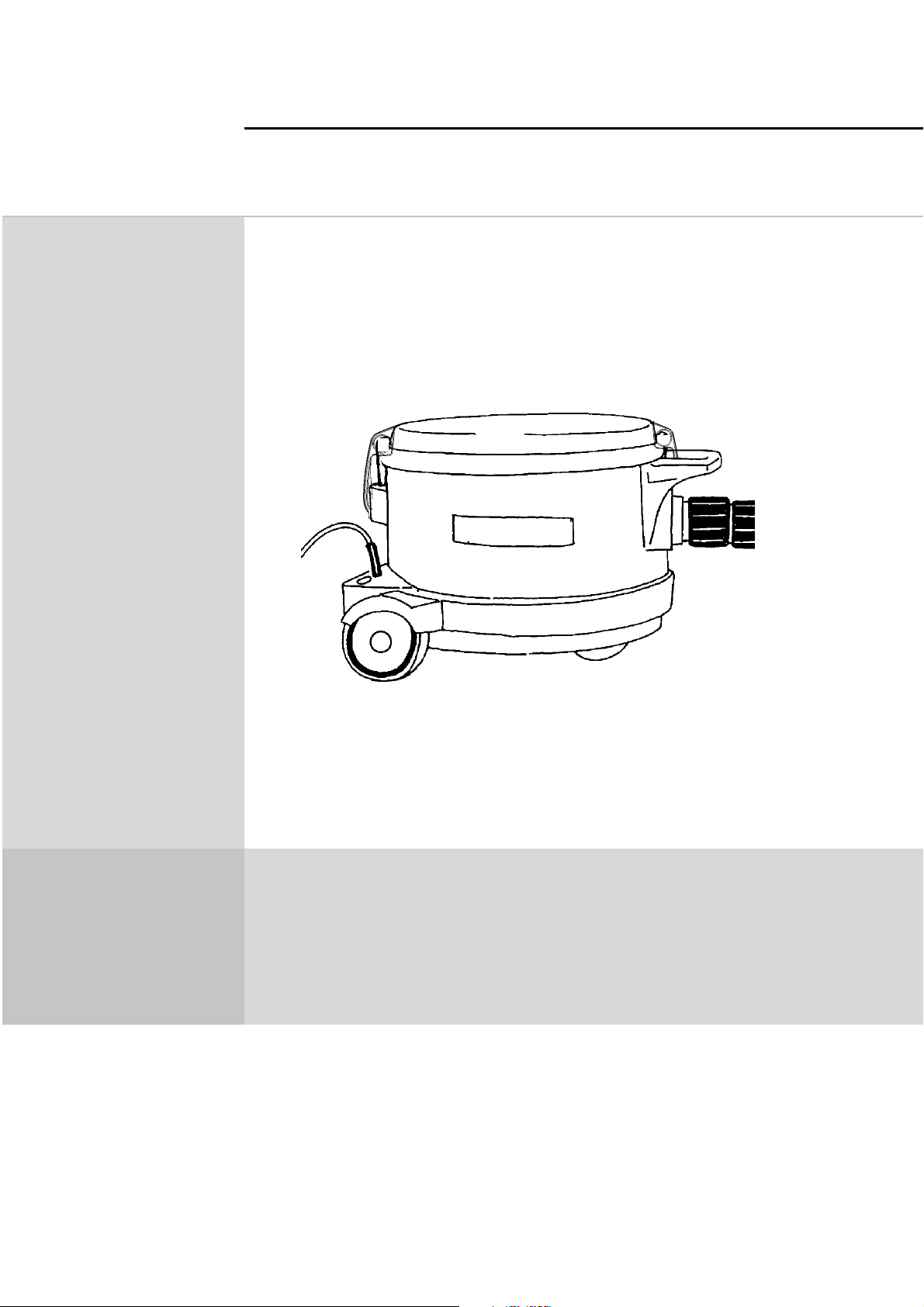
GD 930 & GD 930S2
1
PARTS LIST
822 9401 000
56042413
2000-08
Page 2

WHEN ORDERING PARTS ALWAYS STATE
* MODEL - QUANTITY - PART NUMBER - DESCRIPTION
* Specify the serial number of the machine.
* Use the space below ro record the model and serial number for future reference.
Model______________________________ Serial no._________________________________
NOTES________________________________________________________
_______________________________________________________________
________________________________________________________________
00-082
________________________________________________________________
________________________________________________________________
__________________________________________________________________
__________________________________________________________________
___________________________________________________________________
___________________________________________________________________
_____________________________________________________________________
____________________________________________________________________
_____________________________________________________________________
____________________________________________________________________
____________________________________________________________________
Page 3
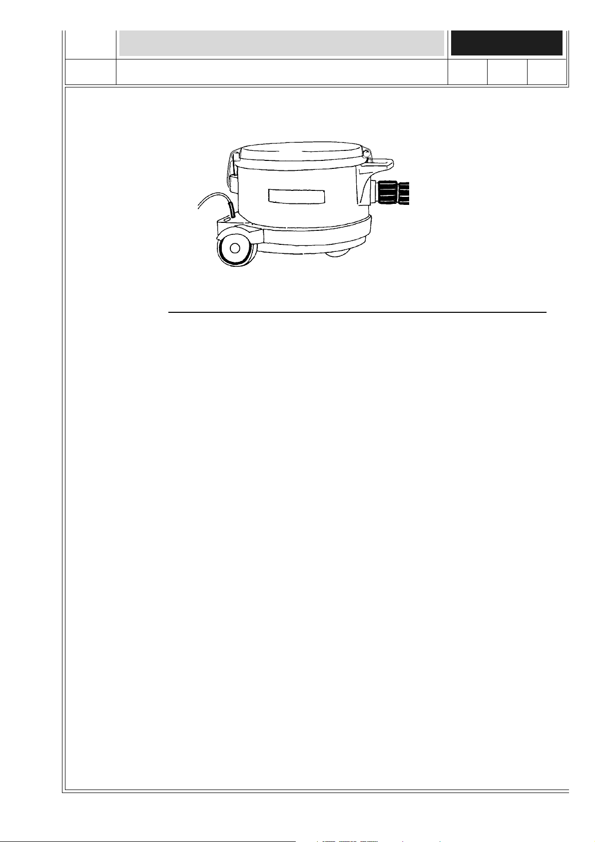
TABLE OF CONTENTS SPARE PARTS
00-08
GD 930 & GD 930S2DRY VACUUM CLEANER 3
DESCRIPTION PLAN
Lower parts, line-drawings 4
Lower parts, part number 5
Fan unit Line drawing 6
Table with fan units, sleeves and cords 7
Upper parts, line-drawings 8
Upper parts, part number 9
Nozzles, line drawings 10
Nozzles, part number 11
Nozzle, line drawings 12
Nozzle, part number 13
Hose, line drawing 14
Hose, part number 15
Tubes, line drawing 16
Tubes, part number 17
Wiring diagrams 18-24
Page 4
SPARE PARTS
4
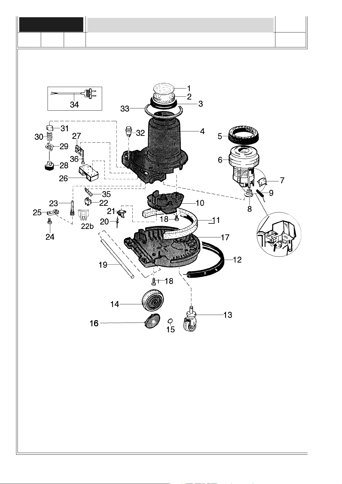
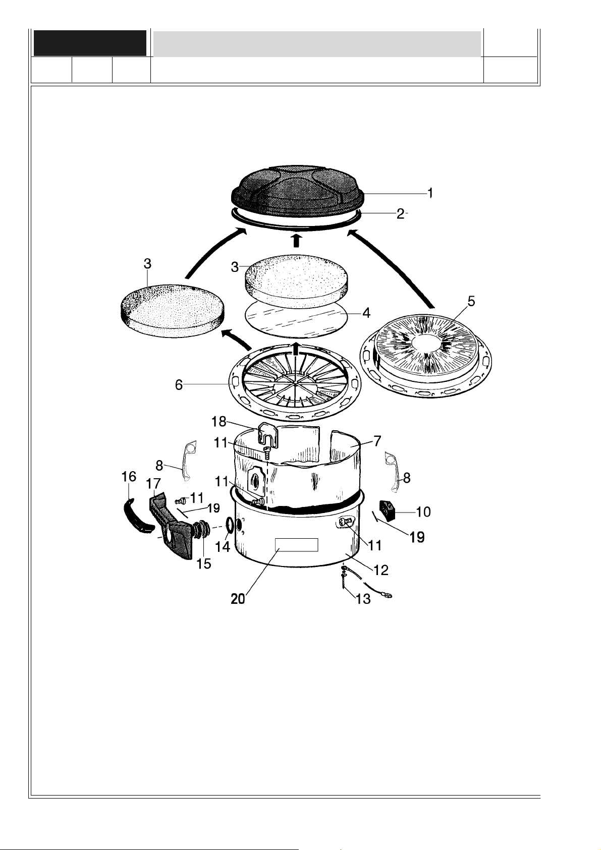
GD 930 GD 930S2 LOWER PARTS
00-08
Page 5

SPARE PARTS
00-08
GD 930 GD 930S2 LOWER PARTS 5
Item No. Qty.Part no. Description
1 1 140 3261 000 Paper filter
2 1 140 1535 000 Filter
3 1 140 2847 000 Gasket
4 1 140 7010 000 Stand, regular GD 930
1 140 7010 010 Stand, S2 versions
1 140 7010 030 Stand UL-listed, for model 905 5313
1 140 7010 080 Stand, UL-listed, for model 905 5314
1 140 7010 090 Stand, S2 UL-listed for model 905 5345
5 1 140 7901 000 Suspension ring, for the new domel motors
1 011 1548 000 Suspension ring, for the old type of motor
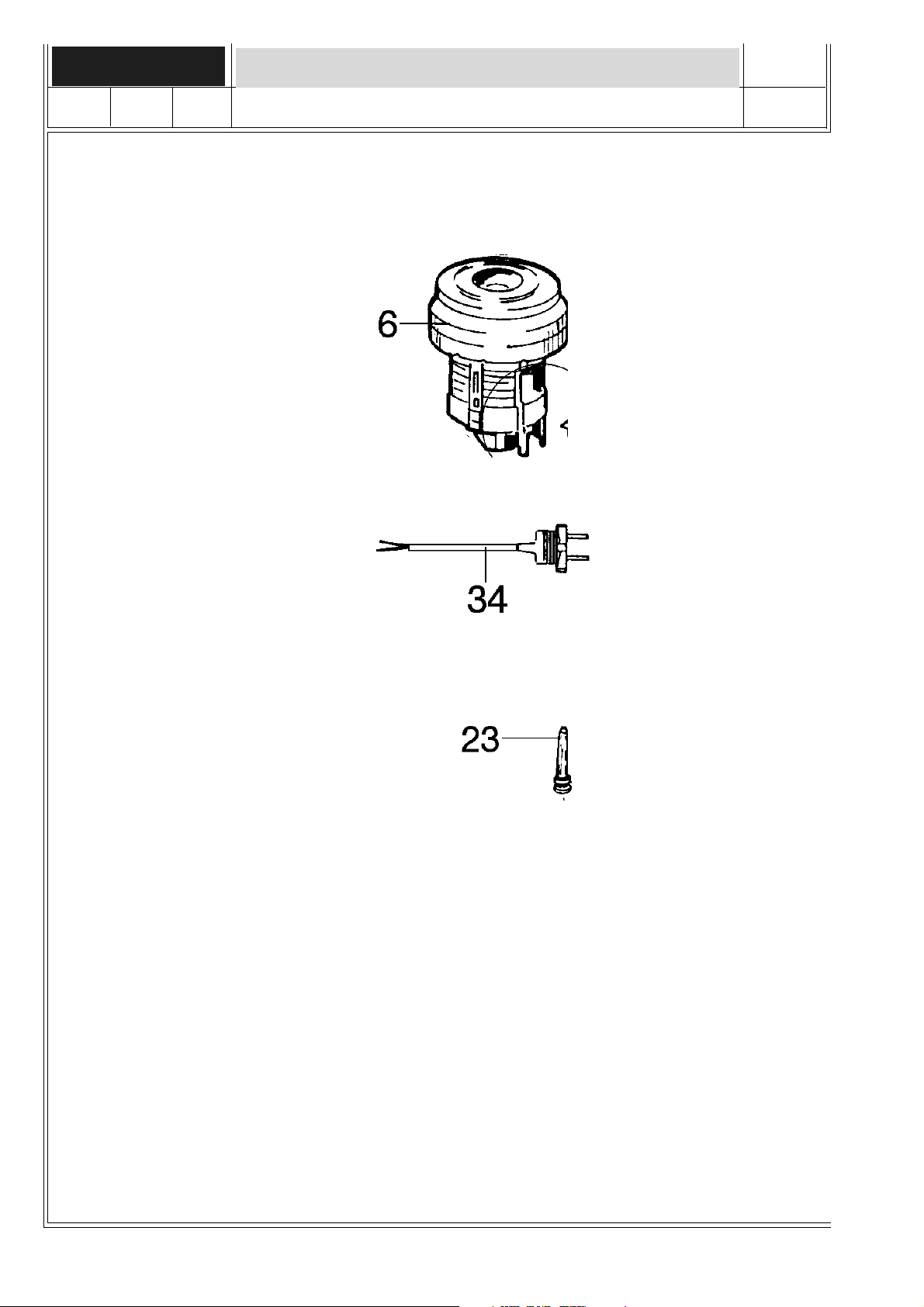
6 1 Fan unit (see table)
7 1 140 8166 010 Capacitor
8 4 140 7016 000 Spring
9 2 001 8619 110 Carbon brush
10 1 140 7012 000 Motor plate
1 140 7012 010 Motor plate UL-listed
11 1 140 7022 000 Silencer
12 1 140 7018 000 Bumper
13 1 140 7025 000 Castor wheel
14 2 140 5055 010 Wheel
15 2 140 5058 000 Locking cap
16 1 140 7835 000 Wheel disc
17 1 140 7011 000 Bottom part
1 140 7011 010 Bottom part UL-list.
18 14 140 9214-070 Screw PTK 50*14
19 1 140 5059 000 Shaft
20 2 140 5694 000 Rivet
21 1 140 3894 000 Thermo switch
22 1 010 9678 000 Extra outlet
22b 1 140 7665 000 Electrical outlet (USA)
23 1 Sleeve (see table)
24 2 140 9214 040 Screw PTK40*14
25 1 056 1014 060 Anti strain clip
1 140 6560 000 Strain clamps UL-list
26 1 140 7026 000 Circuit board S2 220-240V
1 140 7026 010 Circuit board S2 100-120V
27 1 140 7024 000 Anti static board
28 1 140 7033 000 Switch
29 1 140 1508 000 Washer
30 1 140 1522 000 Spring
31 1 140 7805 010 Push button, silver
32 1 140 7023 000 Switch S2 version
33 1 140 7021 000 Gasket
34 Cord set (see table)
35 1 011 7365 000 Protection plate
36 1 140 7027 000 Screw
Page 6
SPARE PARTS
6
FAN UNIT LINE DRAWING
00-08
Page 7
SPARE PARTS
00-08
FAN UNITS & CORDS TABLE
on.dorPon.dorP
on.dorPon.dorPegatloVegatloV
on.dorP
1035509V0320052097041>>00053070410323246041
2035509V0320052097041>>00053070410203246041
3035509V0320052097041>>00053070410213246041
4035509V0420252097041>>01072013900603246041
5035509V0420252097041>>01072013900603246041
6035509V0420252097041>>01072013900009307041
7035509V021/0110152097041>>01072013900013246041
8035509V0010352097041>>01072013900503246041
9035509V0320052097041>>00053070410323246041
egatloVegatloV6.soptinunaF6.soptinunaF
egatloV
6.soptinunaF6.soptinunaF32.sopeveelS32.sopeveelS
6.soptinunaF
32.sopeveelS32.sopeveelS43.sopdroC43.sopdroC
32.sopeveelS
7
43.sopdroC43.sopdroC
43.sopdroC
0135509V0220052097041>>01072013900003407041
1135509V032-0220052097041>>01072013900113246041
2135509V0220052097041>>00053070410213246041
3135509V0210152097041>>01072013900209583041
4135509V0210152097041>>01072013900209583041
5135509V7210452097041>>0107201390>0013246041
0435509V0320052097041>>00053070410323246041
1435509V0420252097041>>01072013900603246041
2435509V0420252097041>>01072013900009307041
3435509V0010352097041>>01072013900503246041
4435509V0320052097041>>00053070410213246041
5435509V0210152097041>>01072013900609583041
Means: New or changed ref. number or/and changed/new specifications
>>
NOTE: New fan units for all GD 930 and GD 930S2 machines.
The spare fan units, will be delivered in a kit with the suspension ring, cables,
suppressor & wiring diagram in a package.
Page 8
SPARE PARTS
UPPER PARTS8
00-08
Page 9

SPARE PARTS
00-08
UPPER PARTS
Item Qty. Part No Description
1 1 140 7802 040 Cover
2 1 140 0061 030 Gasket
3 1 140 1515 010 Filter
4 1 140 3260 000 Paper filter
1 140 5661 000 Hygiene filter
5 1 140 2666 010 Micro filter
6 1 140 2911 000 Filter holder
7 140 7015 040 Dust bag (10 pcs)
1 140 7019 000 Cloth dust bag
8 2 140 7832 000 Snap locking
10 1 140 7834 000 Support
11 8 140 9214 070 Screw PTK 50*14
12 1 140 7020 010 Container (chrome)
1 140 7020 020 Container (paint.inside)
1 140 7020 030 Container (grey painted outside)
13 1 140 5694 000 Rivet
14 1 740 4416 000 O-ring
15 1 140 7013 000 Inlet
16 1 140 7800 000 Handle protection
17 1 140 2915 050 Handle
18 1 140 7014 000 Dust bag lock
19 2 140 7807 000 Wire spring
20 2 140 7877 000 Decal Nilfisk GD 930
2 140 7878 000 Decal Nilfisk GD 930 S2
2 140 7879 000 Decal Euroclean GD 930
2 140 7880 000 Decal KENT GD 930
2 140 7298 000 Decal Jydsk
2 140 7698 000 Decal Aquatech
2 140 7172 000 Decal Yamazaki
9
Page 10

SPARE PARTS
10
NOZZLES
1
5
7
8
10
2
3
6
9
00-08
4
12
11
13
Page 11

SPARE PARTS
00-08
NOZZLES
Item Qty Part No Description
1 140 7087 000 Combi nozzle
21 P 145 9921 000 Elbow
31 P 145 9922 000 Roll
41 P145 9923 000 Shaft
51 P 145 9924 000 Suction channel
61 P 145 9925 000 Pedal
71 P 145 9926 000 Square moulding
81 P 145 9927 000 Cover
91 P145 9928 000 Base plate
10 1 P 145 9929 000 Brush strip
11 2 P 093 1811 000 Spring
12 1 P 145 9930 000 Bottom plate
13 2 P 093 1813 000 Little picker
11
Screw/Skruv LKS KA 35x27
Screw/Skruv LSKSKA 35x16
NOTE
P means: Parts for nozzle 140 7087 000 is depleted
when no longer on stock
Item Part No Description
4 010 3098 250 Crevice nozzle
5 011 3104 230 Small comb. nozzle
Page 12

SPARE PARTS
COMBI NOZZLE12
00-08
Page 13

SPARE PARTS
00-08
COMBI NOZZLE 13
Item Qty. Part No Description
1 011 2332-020 Comb. nozzle, cpl.
2 1 010 6596 010 Thread comb, grey
3 1 010 3144 000 Connection tube
4 1 010 6575 000 Front bearing bush
5 1 010 6586 040 Cover, brown
6 1 010 6581 010 Bearing bush
7 1 010 9861 000 Keeper
8 4 010 6568 000 Retainer
9 2 010 6567 000 Spring
10 1 010 9860 010 Protection bar
11 1 010 9867 000 Brush holder
12 1 010 9868 000 Gasket
13 1 010 6562 000 Bristle insert
14 2 729 5281 010 Screw, RXS B6*12, Z.Pl.
15 1 011 2333 000 Nozzle
16 2 729 5285 010 Screw, RXS B6*19, Z.Pl.
17 1 010 9859 000 Mounting plate
18 1 735 1136 010 Washer, Ø4.3, Z.Pl.
19 1 734 1136 010 Washer, Ø4.3, Z.Pl.
20 1 724 1287 010 Screw, MRX M4*8, Z.Pl.
21 1 010 6565 000 Loop schackle
22 1 014 9536 000 Washer
Page 14

SPARE PARTS
HOSE WITH PARTS14
00-08
Page 15

SPARE PARTS
00-08
HOSE WITH PARTS
Item Qty. Part No Description
1 1 140 2782 060 Hose cpl.
2 1 140 2781 020 Hose, by the metre
3 1 140 5116 000 Bent end piece cpl.
4 1 010 9613 080 Suction control
5 1 010 9614 080 Retainer
6 1 011 6432 510 Bent end piece
7 1 011 1811 070 Handle
8 1 011 1655 020 Protection ring
9 2 140 6630 000 Sleeve
10 1 140 3846 000 Cuff cpl.
11 1 011 1659 030 Outer sleeve
12 1 010 9299 040 Cuff
15
Page 16

SPARE PARTS
TUBES16
00-08
Page 17

SPARE PARTS
00-08
TUBES 17
Item Part No Description
1 011 6431 040 Extension tube, 500 mm
011 6431 030 Extension tube, 200 mm
011 6431 010 Extension tube, 750 mm
011 6431 020 Extension tube, 410 mm
2 011 3199 010 Insert
3 011 8130 040 Telescop. extension tube
Page 18

ELECTRICAL DIAGRAM
18
GD 930 GROUNDED VERSION
FOR THE NEW DOMEL
FAN UNITS
BLUE WIRE TO N
00-08
Page 19

ELECTRICAL DIAGRAM
00-08
GD 930 DOUBLE INSULATED
FOR THE NEW DOMEL
FAN UNITS
BLUE WIRE TO N
19
Page 20

ELECTRICAL DIAGRAM
20
GD 930S2 GROUNDED
FOR THE NEW DOMEL
FAN UNITS
BLUE WIRE TO N
00-08
Page 21

ELECTRICAL DIAGRAM
00-08
GD 930S2 DOUBLE INSULATED
FOR THE NEW DOMEL
FAN UNITS
BLUE WIRE TO N
21
Page 22

ELECTRICAL DIAGRAM
GD 930 GROUNDED W.OUT POWER OUTLET, US22
FOR THE NEW DOMEL
FAN UNITS
00-08
Page 23

ELECTRICAL DIAGRAM
00-08
GD 930S2 GROUNDED US VERSION
FOR THE NEW DOMEL
FAN UNITS
23
Page 24

ELECTRICAL DIAGRAM
24
GD 930 GROUNDED, POWER OUTLET US
FOR THE NEW DOMEL
FAN UNITS
23
00-08
 Loading...