

Page 1
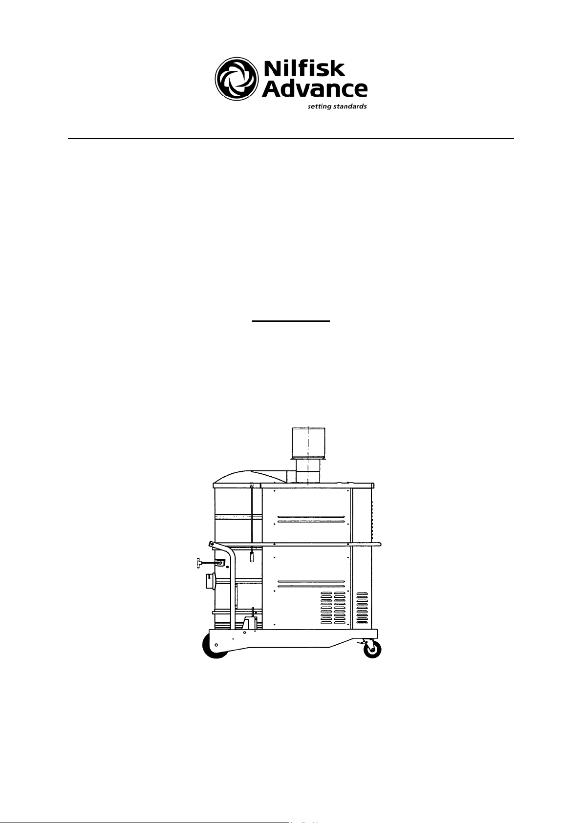
Instruction manual
GB 1133
Categories of application: U, S, C, B1, EOB, K1
ATTENTION
Keep these instructions for future reference!
Page 2

1 Contents
Paragraph Page
1 Contents 2
2 Scope of the instruction manual 3
3 Tests 4
4 Categories of application 5
5 Technical specifications 6
6 General notice on safety 7
7 Filter and emptying systems 8
8 Initial operation 9
9 Adjusting the automatic gear change of the minimum airflow 10,11,12
10 Monitoring the airflow 13
11 Cleaning the filter 14
12 Emptying the container 15
13 Disposal of collected dust 16,17
14 Pre-separator 18
15 Notice on K1 vacuum cleaners used for removing asbestos 19
16 Service 20
Page 3

2 Scope of the instruction manual
This instruction manual is valid for the the following machine types:
GB 1133 – U(L)
GB 1133 – C(M,H)
GB 1133 – S(M) - B1
GB 1133 – C(M,H) - B1
GB 1133 – C(M,H) - EOB/IS
GB 1133 - K1(H)
Meaning of the type name
GB 1033 - series
C(M,H) - category of application (dust class)
EOB - machine type
The machine type “industrial vacuum cleaner (IS)“ is left out. The machine type of
cleaners that have passed the additional “Dust Explosion Protection Test“ is “B1“.
Page 4

3 Tests
All Nilfisk-Advance systems are tested in order to comply with the requirements of
system safety regulations. They have fulfilled the technical safety demands according
to the following special regulations:
- Technical Dust Test
- Mechanical and Electrical Test
- Noise Technology Test
DIN EN ISO 3744
- Additional Dust Explosion Protection Test
Page 5

4 Categories of application
This Nilfisk machine is suitable for removing dusts of the following categories of
application:
“U“ suitable for removing hazardous, dry, not inflammable dusts whose MAK*
limiting value is greater than 1 mg/cm³ (comparable to the new dust class “L“
- light hazard - defined by EN 60335-2-69).
“S“ suitable for removing hazardous, dry, not inflammable dusts whose MAK
limiting value is greater than 0.1 mg/cm³ (comparable to the new dust class
“M“ - medium hazard - defined by EN 60335-2-69).
“C“ suitable for removing hazardous, dry, not inflammable dusts with all MAK
limiting values (comparable to the new dust class “M“) as well as dry, not
inflammable dusts of carcinogenic substances (comparable to the new dust
class “H“ – high hazard – defined by EN 60335-2-69). The cleaned air is fed
back to the workplace atmosphere.
“K1“ suitable for removing hazardous, dry, not inflammable dusts with all MAK
limiting values as well as dry, not inflammable dusts of carcinogenic
substances. The cleaned air is fed back to the workplace atmosphere
(comparable to the new dust class “H“).
*maximale Arbeitsplatz-Konzentration, maximal workplace concentration
Explanation
Since May 1998, Europe has a common norm. Dust removing systems are from now
on divided into three dust classes L, M and H. Older test certificates remain valid until
December 31st, 2002. “Category of application“ is a synonym for “dust class“.
Page 6

5 Technical specifications
Voltage 400 V
Rated power 13,000 W
Vacuum 320 mbar
Connection Ø 70/100 mm
Airflow 750/930 m³/h
Filter area Main filter (U,S,C) 52,000 cm²
Prefilter (K1) 52,000 cm²
Main filter (K1) 60,000 cm²
Minimum airflow 300/580 m³/h
Protection class IP 54
Insulation class F
-1
Noise emission
Sound pressure level measuring as described in DIN EN ISO 3744.
According to the machine guideline Appendix 1, point 1.75 f, the highest sound
pressure level is measured at 1 m distance from the machine at a height of 1.6 m.
The highest value is reached on the right side (view down on the inlet):
77 dB(A).
Page 7

6 General notice on safety
Only original Nilfisk spare parts may be used.
The machine may only be operated by instructed and authorised individuals.
Liquids, aggressive gases, flammable materials or smouldering particles should not
be removed.
The machine may only be used for cleaning dry surfaces and is not suitable for
outdoor use.
The power cord should not be damaged by being driven over, squeezed, pulled tight
or around sharp corners. Keep the power cord away from heated surfaces.
The power cord should be checked at regular intervals for signs of damage or
ageing.
Do not use the machine when the power cord is not in perfect condition.
Only original Nilfisk-Advance spare parts should be used when replacing the power
cord.
When the mains plug is replaced, splash-proof protection and mechanical safety
must be assured.
The replacement of the power cord or the mains plug should be carried out by a
competent person.
After use, before cleaning or any maintenance or adjustment work the mains plug
must be unplugged.
Before connecting the cable, the dust-producing system has to be shut down.
MAINTENANCE
Regular maintenance test: check the bounce separator for damage, the integrity of
the system, the filter and the functioning of the control system. Nilfisk-Advance offers
maintenance contracts which guarantee constant performance and value
preservation of the machines and their technical safety functions by regular checkups.
Page 8

7 Filters and emptying systems
The installed main and exhaust filters are approved by the German Trade
Association Institute for Safety at the Workplace (BIA). The transmission factors are
lower than the limiting values required by relating regulations.
The installed filters normally have a long service life. Exchange of filters should only
be carried out by Nilfisk-Advance Service.
Without the appropriate emptying system, the machine does not match the
requirements specified by relating regulations. In this case, danger to health
cannot be excluded.
Article numbers for filters and emptying systems
Category of application Main filter Disposal system
(dust class) Type A Type B
U (L) 040053
S (M) 040053 027641
C (M, H) 040053 030343 031101
K1 (H) (prefilter) 040053 4 x 02170000 030343 031101
Two different disposal systems are in use:
Type A: Dust bag system
Type B: Disposable container
Page 9

8 Initial operation
Please read these notes of safety before initial operating.
The application scope of the machine is marked on the rating-plate.
Industrial vacuum cleaners are exclusively designed for removing settled dusts.
Extractors are designed for removing dust at that very place where it is produced.
Having removed the system from packaging, check it for completeness and
transportation damage. In case of damage or missing parts please contact NilfiskAdvance immediately. Before connecting the vacuum cleaner to the mains supply,
check that the voltage of the machine specified on the rating-plate corresponds with
the mains voltage.
Switch the motor on to control its direction of rotation.
When it is wrong, a red lamp at the switch housing flashes up.
Extractors: an arrow on the motor housing shows the right direction of rotation.
Working for a long time with the wrong direction of rotation heatens the
vacuum cleaner’s surface up to over 80°C.
When the direction of rotation is wrong two phases in the mains supply (not within the
machine) need to be exchanged. All electrical sockets of the workplace should have
the same phase sequence in order to operate the system in all areas of the
workplace.
Systems with antistatic design (B1)
These machines are not suitable for removing explosive materials, dusts with an
extremely low minimum ignition energy of less than 1 mJ and inflammable liquids.
Do not use others than conductible original Nilfisk-Advance accessories.
Use couplers that only allow connecting and disconnecting the system in voltage-free
condition.
Antistatic systems must be equipped with a protective circuit breaker or a blowout
fuse 16 A (delayed-action fuse).
The use of coupling devices and adapters is not allowed.
The system is ready for use when all equipment has been connected.
Page 10

9 Adjusting the automatic gear change of the minimum airflow
Use the performance profile to adjust the cutoff point for the minimum
airflow of extractors. First of all, find out the minimal airflow that ensures
a good operation of the dust-producing system. Mark this value on the xaxis, then draw a vertical line from here to the curve. Now draw a line
parallel to the x-axis from the point of intersection to the y-axis. This
value describes the vacuum that has to be adjusted at the vacuum
switch when the minimal airflow is no longer sufficient.
When adjusting the vacuum, you have to connect an appropriate
measuring device parallel to the vacuum switch. Throttle the airflow at
the suction inlet until the required value is reached. Now calibrate the
cutoff point by the adjusting screw of the vacuum switch.
When the minimal airflow falls short, the following happens after a few
seconds:
- the red warning light flashes up.
- the floating contact in the switch housing switches. This contact (6 A at
a
voltage of 230 V, AC11) manages the connection of the control circuit
of
the dust-producing system to the extractor or to control an external
optical or acoustical signal.
Page 11

The works for configuring an extractor (connecting the cable, adjusting
the cutoff point) may only be carried out by a technician or skilled
personnel using suitable tools.
When using the vacuum cleaner outdoors, use only a type H07RN-F
cable.
Connecting the cable must be carried out according to the manual added
to the machine.
Even when the extractor is switched off, the interlock circuit might still
carry external voltage from the dust-producing system.
When the airflow control has cut off the dust-producing system, the main
switch has to be switched off as well in order to prevent an unintentional
start of the dust-producing system (after a malfunction has been
removed).
The recirculating airflow mustn’t exceed the 50 per cent of the incoming
airflow in order to comply with the required limiting values.
In case of variation (when high-quality separators are used or the
incoming air is very clean), the evidence of complying with the limiting
values has to be proved
.
Page 12

GB 1133 Performance profile
Page 13

10 Monitoring the airflow
All Nilfisk vacuum cleaners - except category of application “U“ are fitted with a manometer that allows you to monitor the
minimum airflow in order to guarantee an optimal air speed
within the suction hose. When you lift the floor nozzle into the
air and the manometer’s pointer turns from the green into the
red zone, the main filter needs to be cleaned or the dust bag
is full and needs to be replaced.
Extractors
When the cutoff point is reached, the dust-producing system is switched off
automatically and the red warning light flashes up. Clean the main filter or replace the
dust bag.
The fill level of the dust bag/dust collecting container has to be checked at regular
intervals. Monitoring the fill level/automatic gear change (extractors) is no guarantee
that the bag is not full.
Page 14

11 Cleaning the filter
Nilfisk-Advance systems are fitted with a device for cleaning the main filter. First of
all, switch the machine off. Then move the shaker handle placed at the container
vigorously with a push-pull movement.
Extractors
When the dust-producing system is shut down automatically, it needs to be switched
off manually before cleaning the filter or replacing the dust bag. Otherwise, an
hazardous situation could occur if after these works, the dust-producing system
restarts automatically.
After the main filter has been cleaned, the manometer’s pointer must return to the
green area or the red warning light has to go out. Otherwise, the main filter has to be
replaced.
K1 vacuum cleaners
When the pointer is still in the red area or the warning light does not go out, the
prefilter has to be replaced as well.
Page 15

12 Emptying the container
Industrial vacuum cleaners with antistatic design need to be emptied after
every single use.
First of all, switch the motor off. Wait a moment until the dust has settled down before
you separate the dust collecting container from the upper part of the machine:
Lower the container by using the lifting mechanism.
Switch the motor on again in order to prevent dust
falling down from the filter.
Move the dust collector forwards.
Replace the disposal system.
Move the dust collector back under the machine.
Switch the motor off.
Push the dust collector upwards by using the lifting
mechanism.
Page 16

13 Disposal of collected dust
Category of application: “U“
The are no particular prescriptions, but take care that no one around you will be
affected by the dust. The disposal of the collected dust has to be carried out
according to local prescriptions.
Category of application: “S“
Type A: Dust bag system Art. 027 641
Having opened the system, remove the plastic
bag’s edge carefully from the container’s edge
that it is covering. Close the bag’s opening and
take it out of the container.
Put a new dust bag into the container. Take care
that it fits the bottom and the walls. Pull the bag’s
edge over the container’s edge and smooth it down.
Machines of this category of application can be used
without a dust bag. In this case please take care that
the removal of the dust takes place in a special area
and use a respiratory protection mask.
Page 17

Category of application: “C“ and “K1“
Type B: Disposable container Art.no. 031 101
When the container has been torn away from the
machine, close it by the lid and fix the lid by the
clamp ring.
Type A: Dust bag system Art.no. 030 343
Leave the hose connected or close by shutter cap!
Having opened the system, carefully remove the
plastic bag which that is covering the container’s
edge. Close the bag’s opening. Now remove the
cornered back part of the bag’s flange carefully
from the inlet. While doing this, hold the fastening
ring placed on the inlet.
The plastic connection gets visible. It can be closed
tight by the binder.
Having assured that the dust cannot escape from the
dust bag, release the fastening ring from the inlet.
The dust bag can now be removed from the container
without any risk.
Put a new dust bag into the container. Its connector
must point at the inlet.
Now push the flange onto the inlet until fits tight.
The plastic bag has to fit well the bottom and walls of
the container. Tear the edge of the bag above the
edge of the container and smooth it down.
Page 18

14 Pre-separator
The system can connect to secondary interceptor
tanks for even greater waste capacity of 200 litres
at a time. The lid fitting both sizes of pre-separators
(125 and 200 litres) and the hose connection have
to be ordered separately.
The separator trolley runs on three wheels. A preseparator fitted with such a trolley can comfortably
be transported by a forklift.
The machine and the pre-separator can easily be
connected by a special connector that makes their
transport more comfortable.
Category of application S: a plastic bag (030 370)
is used for the disposal of collected dust.
Category of application C: the pre-separator’s
container is used as a disposable container. It is
closed by a lid (030 715) and a lock ring (030 717)
before disposal.
Page 19

15 Notice on K1 vacuum cleaners used for removing asbestos
A vacuum cleaner that has been used for removing asbestos in a contaminated area
may no longer be used in a non-contaminated area.
An exception is possible when the vacuum cleaner has been decontaminated
completely, that means not only the outside, but also the inside of the vacuum
cleaner (cooling air passages, the installation space for electrical resources or the
resources themselves). The persons in charge is obliged to write it down and sign a
protocol.
Fixed filters may only be replaced by skilled personnel special areas
(decontamination stations).
For a dust-free transport, the vacuum cleaner has to be emptied, the shutter cap of
the suction inlet has to be mounted, the exhaust outlets have to be closed (e.g. by
adhesive tape) and the lifting mechanism has to be locked.
The accessories in use have to be transported in closed plastic bags.
Use our exhaust air accessory kits to guide the exhaust air outdoors!
Art.no. 021 753 for 70 mm suction inlet
Reduction tube (Ø 100 mm)
5 m exhaust air hose (Ø 100 mm)
Art.no. 021 751 for 100 mm suction inlet
Reduction tube (Ø 150 mm)
5 m hose (Ø 150 mm)
Page 20

16 Service
Nilfisk-Advance Limited
Newmarket Road
Bury St. Edmunds
Suffolk IP33 3SR
Tel: 01284 763163
Fax: 01284 750562
Internet: www.nilfisk-advance.com
__________________________________________________________
Specifications and details are subject to change without prior notice July 1999
 Loading...