

Page 1
Dynamics 440
Betriebsanleitung ...........................2
Operating Instructions ....................8
Notice d'utilisation ....................... 14
Gebruiksaanwijzing ...................... 20
Istruzioni sull'uso ......................... 26
Driftsinstruks ............................... 32
Bruksanvisning ............................. 38
Driftsvejledning............................ 44
Käyttöohje ................................... 50
Navodilo za uporabo ................... 56
Uputstvo za rad ............................ 62
Prevádzkový návod ..................... 68
Provozní návod ............................ 74
Instrukcja obsługi........................ 80
Kezelési utasítás.......................... 86
Instrucciones de manejo............... 92
Instruções de operação................. 98
Οδηγίες λειτουργίας ................104
65318 - 020500
Page 2
EG - Konformitätserklärung
Déclaration de conformité CE
Wap Reinigungssysteme GmbH & Co.
Guido-Oberdorfer-Straße 2-8
D-89287 Bellenberg
Erzeugnis:
Typ:
Beschreibung:
Die Bauart des Gerätes entspricht
folgenden einschlägigen
Bestimmungen:
Angewendete harmonisierte
Normen:
Angewendete nationale Normen
und technische Spezifikationen:
ppa. Rau, Dipl. Ing. (FH)
Leitung Forschung und Entwicklung
EU Declaration of Conformity Dichiarazione di conformità CE
Wap Reinigungssysteme GmbH & Co.
Guido-Oberdorfer-Straße 2-8
D-89287 Bellenberg
Product:
Type:
Description:
The design of the unit corresponds
to the following pertinent
regulations:
Applied harmonised standards:
Applied national standards and
technical specifications:
ppa. Rau, Dipl. Ing. (FH)
Head of Research and Development
Schmutzsauger
Dynamics 440
400 V 3~, 4000 W
EG-Maschinenrichtlinie 89/392/EWG
EG-Niederspannungsrichtlinie 73/23/EWG
EG-Richtlinie EMV 89/336/EWG
EN 292
EN 60335-2-2
EN 60335-2-69
EN 50081, EN 50082
DIN EN 60335-1
IEC 335-2-69
DIN VDE 0700 T 205
Bellenberg, 03.02.1997
Vacuum Cleaner
Dynamics 440
400 V 3~, 4000 W
EC Machine Directive 89/392/EWG
EC Low-voltage Directive 73/23/EWG
EC EMV Directive 89/336/EWG
EN 292
EN 60335-2-2
EN 60335-2-69
EN 50081, EN 50082
DIN EN 60335-1
IEC 335-2-69
DIN VDE 0700 T 205
Bellenberg, 03.02.1997
Wap Reinigungssysteme GmbH & Co.
Guido-Oberdorfer-Straße 2-8
D-89287 Bellenberg
Produit:
Type:
Description:
La construction de l’appareil est
conforme aux réglementations
afférentes suivantes:
Normes harmonisées appliquées:
Normes nationales et spécifications
techniques appliquées:
ppa. Rau, Dipl. Ing. (FH)
Direction Recherche et
Développement
Wap Reinigungssysteme GmbH & Co.
Guido-Oberdorfer-Straße 2-8
D-89287 Bellenberg
Prodotto:
Tipo:
Descrizione:
La costruzione dell' apparecchio è
conforme alle seguenti direttive
specifiche:
Norme armonizzate applicate:
Norme nazionali applicate e
specifiche tecniche:
ppa. Rau, Dipl. Ing. (FH)
Direttore Ricerca e Sviluppo
Aspirateurs de saletés
Dynamics 440
400 V 3~, 4000 W
Directive CE relative aux machines 89/392/EWG
Directive CE relative à basse tension 73/23/EWG
Directive CE EMV 89/336/EWG
EN 292
EN 60335-2-2
EN 60335-2-69
EN 50081, EN 50082
DIN EN 60335-1
IEC 335-2-69
DIN VDE 0700 T 205
Bellenberg, 03.02.1997
Aspiratore per sostanze sporche
Dynamics 440
400 V 3~, 4000 W
Direttiva CE sulle macchine 89/392/EWG
Direttiva CE sulla bassa tensione 73/23/EWG
Direttiva CE sulla compatibilità
elektromagnetica 89/336/EWG
EN 292
EN 60335-2-2
EN 60335-2-69
EN 50081, EN 50082
DIN EN 60335-1
IEC 335-2-69
DIN VDE 0700 T 205
Bellenberg, 03.02.1997
EG-Verklaring van overeenstemming
Wap Reinigungssysteme GmbH & Co.
Guido-Oberdorfer-Straße 2-8
D-89287 Bellenberg
Produkt:
Type:
Beschrijving:
De constructie van het apparaat
voldoet aan de volgende van
toepassing zijnde voorschriften:
Toegepaste geharmoniseerde
normen:
Toegepaste nationale normen en
technische specificaties:
ppa. Rau, Dipl. Ing. (FH)
Chef onderzoek en ontwikkeling
Vuilzuiger
Dynamics 440
400 V 3~, 4000 W
EG-machinerichtlijn 89/392/EWG
EG-laagspanningsrichtlijn 73/23/EWG
EG-richtlijn EMV 89/336/EWG
EN 292
EN 60335-2-2
EN 60335-2-69
EN 50081, EN 50082
DIN EN 60335-1
IEC 335-2-69
DIN VDE 0700 T 205
Bellenberg, 03.02.1997
Atestado de conformidad de la UE
Wap Reinigungssysteme GmbH & Co.
Guido-Oberdorfer-Straße 2-8
D-89287 Bellenberg
Producto:
Modelo:
Descripción:
La construcción de la máquina
corresponde a las siguientes
normas específicas:
Normas armonizadas aplicadas:
Normas nacionales aplicadas y
especificaciones técnicas:
ppa. Rau, Dipl. Ing. (FH)
Director Investigación y Desarrollo
Aspirador de suciedad
Dynamics 440
400 V 3~, 4000 W
R. de la UE para máquinas 89/392/EWG
R. de la UE para baja tensión 73/23/EWG
R. de la UE para la compatibilidad electromagnética 89/336/EWG
EN 292
EN 60335-2-2
EN 60335-2-69
EN 50081, EN 50082
DIN EN 60335-1
IEC 335-2-69
DIN VDE 0700 T 205
Bellenberg, 03.02.1997
Page 3
Atestado de
conformidade da UE
∆ήλωση ανταπόκρισης ΕΟΚ
Wap Reinigungssysteme GmbH & Co.
Guido-Oberdorfer-Straße 2-8
D-89287 Bellenberg
Produto:
Modelo:
Descrição:
A construção da máquina
corresponde às seguintes normas
específicas:
Normas harmonizadas aplicadas:
Normas nacionais aplicadas e
especificações técnicas:
ppa. Rau, Dipl. Ing. (FH)
Diretor de Pesquisas e
Desenvolvimento
EF-konformitetserklæring
Wap Reinigungssysteme GmbH & Co.
Guido-Oberdorfer-Straße 2-8
D-89287 Bellenberg
Produkt:
Type:
Beskrivelse:
Apparatets konstruksjonstype er i
samsvar med følgende gjeldende
bestemmelser:
Anvendte harmoniserte
standarder:
Anvendte nasjonale standarder og
tekniske spesifikasjoner:
Aspirador de sujidades
Dynamics 440
400 V 3~, 4000 W
Directiva UE para máquinas 89/392/EWG
Directiva UE para baixa tensão 73/23/EWG
Directiva para a compatibilidade
electromagnética 89/336/EWG
EN 292
EN 60335-2-2
EN 60335-2-69
EN 50081, EN 50082
DIN EN 60335-1
IEC 335-2-69
DIN VDE 0700 T 205
Bellenberg, 03.02.1997
Smussoppsugeren
Dynamics 440
400 V 3~, 4000 W
EF-maskindirektiv 89/392/EEC
EF-lavspenningsdirektiv 73/23/EEC
EF-direktiv elektromagnetisk
kompatibilitet 89/336/EEC
EN 292
EN 60335-2-2
EN 60335-2-69
EN 50081, EN 50082
DIN EN 60335-1
IEC 335-2-69
DIN VDE 0700 T 205
Wap Reinigungssysteme GmbH & Co.
Guido-Oberdorfer-Straße 2-8
D-89287 Bellenberg
Προϊόν:
Τύπος:
Περιγραφή:
Ο κατασκευαστικός τύπος της
συσκευής ανταποκρίνεται στους
ακόλουθους σχετικούς
κανονισµούς:
Εφαρµοσθείσες εναρµονισµένες
προδιαγραφές:
Εφαρµοσθείσες εθνικές
προδιαγραφές και τεχνικοί
προσδιορισµοί:
∆ιπλ. µηχ. A. Rau
Υπεύθυνος ερευνητικού τµήµατος
Wap Reinigungssysteme GmbH & Co.
Guido-Oberdorfer-Straße 2-8
D-89287 Bellenberg
Produkt:
Typ:
Beskrivning:
Apparatens konstruktion motsvarar
följande tillämpliga bestämmelser:
Tillämpade harmoniserade normer:
Tillämpade nationella normer och
tekniska specifikationer:
µηχανής αναρρόφησης
Dynamics 440
400 V 3~, 4000 W
Οδηγία περί µηχανών ΕΟΚ 89/392/ΕΟΚ
Οδηγία χαµηλών τάσεων ΕΟΚ 73/23/ΕΟΚ
Οδηγία περί ηλεκτροµαγνητικής
συµβατότητας 89/336/ΕΟΚ
EN 292
EN 60335-2-2
EN 60335-2-69
EN 50081, EN 50082
DIN EN 60335-1
IEC 335-2-69
DIN VDE 0700 T 205
Bellenberg, 03.02.1997
EG-försäkran om
överensstämmelse
Smutssugaren
Dynamics 440
400 V 3~, 4000 W
EG-maskindirektiv 89/392/EWG
EG-lågspänningsdirektiv 73/23/EWG
EG-direktiv EMK 89/336/EWG
EN 292
EN 60335-2-2
EN 60335-2-69
EN 50081, EN 50082
DIN EN 60335-1
IEC 335-2-69
DIN VDE 0700 T 205
ppa. Rau, Dipl. Ing. (FH)
Leder forskning og utvikling
EF-overensstemmelsesattest
Wap Reinigungssysteme GmbH & Co.
Guido-Oberdorfer-Straße 2-8
D-89287 Bellenberg
Produkt:
Type:
Beskrivelse:
Konstruktionen af dette apparat
opfylder følgende gældende
bestemmelser:
Anvendte harmoniserede
standarder:
Anvendte tyske standarder og
tekniske specifikationer:
ppa. Rau, Dipl. Ing. (FH)
Leder forskning og udvikling
Bellenberg, 03.02.1997
Smudssugeren
Dynamics 440
400 V 3~, 4000 W
EF-maskindirektiv 89/392/EØF
EF-lavspændingsdirektiv 73/23/EØF
EF-direktiv vedr. elektromagnetisk
fordragelighed 89/336/EØF
EN 292
EN 60335-2-2
EN 60335-2-69
EN 50081, EN 50082
DIN EN 60335-1
IEC 335-2-69
DIN VDE 0700 T 205
Bellenberg, 03.02.1997
ppa. Rau, Dipl. Ing. (FH)
Ledare för forskning och utveckling
EY-Vaatimustenmukaisuusvakuutus
Wap Reinigungssysteme GmbH & Co.
Guido-Oberdorfer-Straße 2-8
D-89287 Bellenberg
Tuote:
Tyyppi:
Kuvaus:
Tämän laitteen rakenne vastaa
seuraavia määräyksiä:
Käytetyt harmonisoidut normit:
Käytetyt kansalliset normit ja
tekniset spesifikaatiot:
ppa. Rau, Dipl. Ing. (FH)
Kehitys- ja tutkimusjohtaja
Bellenberg, 03.02.1997
Likaimurin
Dynamics 440
400 V 3~, 4000 W
EY-konedirektiivi 89/392/EWG
EY-pienjännitedirektiivi 73/23/EWG
EY-direktiivi EMV 89/336/EWG
EN 292
EN 60335-2-2
EN 60335-2-69
EN 50081, EN 50082
DIN EN 60335-1
IEC 335-2-69
DIN VDE 0700 T 205
Bellenberg, 03.02.1997
Page 4
Dynamics 440
1
1
2
R
3
4
5
8
7
6
9
10 11 12
2
3 4
1
1
2
R
2
Page 5
Dynamics 440
R
5
8
6 7
1
9 10
2112 1
1
R
3
2
3
4
11
7
6
5
14
5
6
2
1
12 13
8
15 16
2
10
11
4
3
Page 6

FOR YOUR OWN
SAFETY
Before putting the
cleaner into operation, be
sure to also read the
enclosed operating
instructions thoroughly
and keep them close at
hand for future reference.
The cleaner may only be
used by persons trained in
its use and expressly
authorised to use it.
GENERAL
Operation of this cleaner
is subject to the
applicable national
regulations.
In addition to these
operating instructions and
the binding regu
lations on accident
prevention
applicable in the country
of use, the generally
acknowledged technical
rules for safe and correct
working must also be
observed.
*)
4
For tested safety cleaners of dust clases L,M, H and B1, observe
the instructions in the operating manual.
Any method of work
endangering health or
safety is forbidden!
HEALTH-ENDANGERING
DUSTS
*
)
This cleaner is not suitable
for picking up health-
endangering dusts.
FIRE AND EXPLOSION
HAZARD
The following materials
must not be picked up
with the cleaner:
_ Hot materials (glowing
cigarettes, hot ashes,
etc.)
_ Inflammable, explosive
or aggressive fluids
(e.g. petrol, solvents,
acids, alkalines, etc.)
_ Inflammable, explosive
dusts (e.g. magnesium
or aluminium dust,
etc.).
APPLIANCE PLUG
SOCKET
Before connecting any
appliance to the appliance
plug socket, the cleaner
must always be
switched off.
If appliances are
connected to the
appliance plug socket,
ensure that these
appliances are also
switched off when being
connected to the
appliance plug socket.
CAUTION!
The operating
instructions and the
safety precautions
contained therein must
be observed when
using appliances
connected to the
appliance plug socket
of the cleaner.
USING FOR THE FIRST
TIME
Before using the cleaner
for the first time, check
that it is in a good and
safe condition.
Plugs and connectors of
mains leads must be at
least splash water-proof.
Check the mains
connection and mains
plug.
Inspect the mains lead at
regular intervals for
damage or signs of
ageing. Use the cleaner
only
when the mains lead is in
a good and safe
condition.
(Damaged mains leads
present a danger of
electric shocks!)
Use the cleaner only with
an undamaged filter
element.
Page 7

DURING OPERATION
Take care not to damage
the mains lead (e.g. by
driving over, pinching or
dragging). Pull out the
mains plug only directly at
the plug, i.e. not by
pulling at the mains lead.
Before picking up liquids,
the filter bag must be
removed and the function
of the float switch
checked.
If foaming is observed,
stop work immediately
and empty the tank.
MAINTENANCE AND
REPAIR
CAUTION!
Before cleaning and
servicing the cleaner,
always remove the
mains plug.
Carry out only
maintenance operations
described in these
operating instructions.
Use only original Wap
spare parts.
Do not make any
technical modifications to
the cleaner.
CAUTION!
Your safety could be
endangered as a result!
For all other
maintenance and repair
work, please contact
the Wap Service
department or an
authorised specialist
workshop!
ELECTRICAL
EQUIPMENT
Check the rated voltage
of the cleaner before
connecting it to the mains
power supply. Ensure
that the voltage specified
on the rating plate
corresponds to the local
mains voltage.
When connected to the
mains power supply with
a mains lead of type H 07
RN-F 3G 1.5 mm², the
cleaner may also be used
outdoors.
When using an extension
lead or replacing the
mains lead, the lead type
specified by the
manufacturer must always
be used.
We recommend that the
power supply to the
cleaner be connected via
an earth-leakage circuit
breaker which interrupts
the power supply either if
the earth leakage current
exceeds 30 mA for 30
ms, or it contains an
earthing test current
circuit.
When using an extension
lead, observe the
minimum cross-sections of
the leads:
Cable length Cross-section
m mm²
up to 20 1.5
20 to 50 2.5
Always arrange the
current-carrying parts
(plug sockets, plugs and
connectors) and lay
extension leads so that
the protection class of the
cleaner is maintained.
CAUTION!
Never spray the top
section of the cleaner
with water: Danger for
persons, danger of short
circuits.
The latest edition of the
IEC Regulations must be
observed.
5
Page 8

Dynamics 440
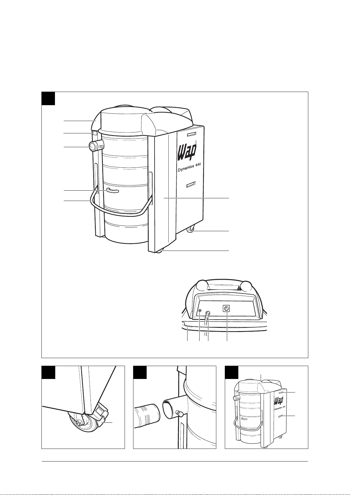
1 Description
1.1 Illustration
(Fig. 1)
1 Cover
2 Rating plate
3 Inlet fitting
4 Tank
5 Tank lock
Description
6 Fixed castors
7 Swivel castors with brake
8 Chassis
9 Handle
10 Compressed-air
connection
11 Power cable
12 Main switch
1.2 Application
The Dynamics 440 is an
industrial vacuum cleaner of the
usage class M and is thus
suitable when used properly for
vacuuming up dry, nonflammable dusts with a lower
toxic limit > 1 mg/m3.
1.3 Inspections and
approvals
Protection class 1
Protection type IP X4
Radio interference
suppression level N
At a filter surface load
< 500 m3 x m-2 x h-1 the vacuum
cleaner has a permeability
< 0.5 % and thus corresponds to
the usage class “M” due to its
other equipment.
The filter paper of the filter
cartridge has been tested by the
German BIA as per ZH 1/487,
Para. 2. The mean permeability
is certainly less than 0.1 % at a
velocity in blower stream of
0.05 m/sec.
Electrotechnical tests must be
conducted as per VDE 0105 in
accordance with the regulations
of the German Accident
Prevention Regulation (VBG4)
and as per DIN VDE 0701 Parts 1
and 3. These tests are required
in accordance with DIN VDE
0702 at regular intervals and
following servicing or changes.
Electrotechnically tested by the
German SEV and TÜV in
accordance with the test
methods/principles
DIN VDE 0700 Part 1
DIN VDE 0700 Part 2
DIN VDE 0700 Part 205.
Based on the test in accordance
with DIN VDE 0700 Part 205,
the vacuum cleaner is suitable
for increased loading during
commercial use.
The test as per DIN VDE 0700
Parts 1 and 205 showed that the
technical safety requirements
with regard to the electrical
safety are also fulfilled when
vacuuming up a water/air
mixture.
8
Page 9

Dynamics 440
1.4 Technical data
Dynamics
440
Voltage volts 400
Frequency Hz 50
Power connection 3-phase w/o neutral,
clockwise phase
sequence
Connected load watts 4000
Max. volume flow (air) max. m3/h 432
max. l/min 7200
Max. vacuum max. hPa 230
Filter surface area m
2
5
Separating capacity % 99,95
Filter blow-off
Compressed air
(oil and water-free) bar 8
Measuring surface sound
pressure level at 1 m
distance as per DIN 45 635,
Part 1 (4/84) in open field
at maximum volume flow dB(A) 70
Description
1.5 Accessories, additional
equipment
Tank volume l 100
Power cable m 5
Suction hose diameter mm 70
Width mm 750
Depth mm 1250
Height mm 1350
Weight kg 195
Protection class 1
Protection type (splash-proof) IP X4
Radio-interference
suppression level EN 50081
Filter element Part No. 34931
“Special” filter element with non-stick
coating Part No. 26736
Please see the “Accessories, Vacuum-Cleaner and Safety VacuumCleaner Systems” chapter of our catalogue for the wide range of
accessories available for this vacuum cleaner.
9
Page 10

Dynamics 440
2 Use/Operation
2.1 Setting up vacuum
cleaner
The vacuum cleaner must be set
up on a firm surface. The
surface must be able to safely
support the weight of the
vacuum cleaner and must be
vibration-free.
CAUTION!
When setting up the vacuum
cleaner, a minimum distance of
500 mm must be maintained to
the surrounding walls or objects.
CAUTION!
At an ambient temperature from
25 °C sufficient air circulation
(cooling) must be provided at the
set-up location.
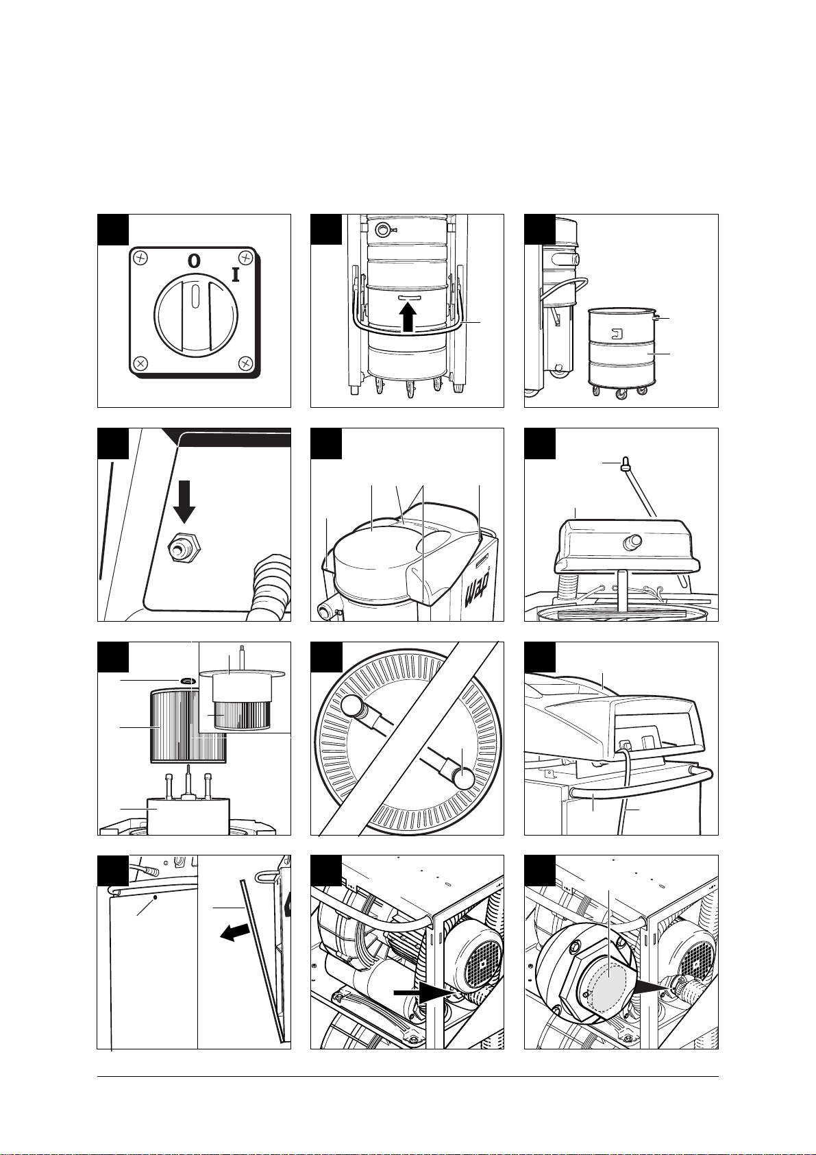
(Fig. 2)
Use/Operation
l Set up vacuum cleaner at
desired location.
l Lock swivel castors on
vacuum cleaner by pressing
brake (1).
2.4 Vacuuming
Never vacuum up flammable
materials or liquids.
After vacuuming up liquids, the
filter cartridge is damp. A damp
filter cartridge can become
blocked faster when dry
materials are vacuumed up. For
this reason the filter cartridge
should be dried or replaced with
a dry cartridge prior to dry
vacuuming.
2.5 Operating vacuum
cleaner
2.5.1 Before switching on
(Fig. 4)
Before switching the vacuum
cleaner on, check whether the
exhaust air outlet (1) is free and
the cooling air inlet (2) of the
motor is not covered or blocked
and clear if necessary.
2.2 Connecting suction
hose
(Fig. 3)
Pull locking pin to connect or
remove the suction hose.
2.3 Electrical connection
The operating voltage indicated
on the rating plate must
correspond to the mains voltage.
l Insert plug of power cable
into a properly installed CEE
outlet (clockwise phase
sequence, connected load 3 x
16 A) . Make sure vacuum
cleaner is switched off.
10
2.5.2 Switching vacuum
cleaner on/off
(Fig. 5)
Operate unit switch:
Switch position “I”:
Vacuum cleaner runs.
2.6 Following work
Switch position “0”:
Vacuum cleaner is switched off.
If the vacuum cleaner is not
required for a longer period of
time, pull the mains plug out of
the electrical outlet.
Page 11

3 Care/Maintenance
Dynamics 440
3.1 Important safety
precautions
CAUTION!
Always pull out the mains plug
before performing cleaning or
maintenance work on the
vacuum cleaner.
3.2 Maintenance schedule
Activity
3.3 Emptying tank
3.4.1 Blowing off filter
3.4.2 Replacing filter element
Only carry out maintenance
work described in these
operating instructions and use
only genuine WAP spare parts.
Do not make any technical
changes to the vacuum cleaner.
CAUTION!
Changes of this type could
endanger your safety.
As required
Monthly
l
l
l
Please contact Wap Customer
Service or an authorised
workshop for further
maintenance and repair work.
3.3 Emptying tank
(Fig. 6)
l Switch off vacuum cleaner by
setting main switch to “0”
position.
l Swing bar (1) of tank lock
upward; tank is lowered.
l Roll out tank (2).
(Fig. 7)
l Dispose of tank content in
accordance with legal
regulations.
l Roll in tank (2). Handle (3)
must face toward front.
l Swing bar (1) of tank lock
downward; tank is raised and
locked.
3.4 Filter element
3.4.1 Blowing off filter
(Fig. 8)
With vacuum cleaner switched
on:
l Connect compressed-air hose
to connection with quick
coupling and leave connected
for approx. 10 seconds, then
remove compressed-air hose
again.
Compressed air: Maximum
8 bar.
3.4.2 Changing filter element
(Fig. 9)
l Pull mains plug.
l Unlock four quick-lock screws
(1) of cover (2) by turning 90°
and pull off.
l Lift off cover (2) and thread
out power cable.
(Fig. 10)
l Disconnect connection hose
of filter blow-off (3).
l Lift off cover (4) upward and
lay toward rear on vacuum
cleaner.
(Fig.11)
l Pull out filter carrier ring (5)
with filter element (6).
(Fig. 11)
l Lay filter carrier ring (5)
upside down on vacuum
cleaner.
l Screw off hand screw (7).
Care/Maintenance
11
Page 12

Dynamics 440
l Pull off filter element (6)
upward.
l Dispose of used filter element
in accordance with legal
regulations.
Part No. for filter element:
34931.
(Fig. 12)
l Insert new filter element
centred.
l Make sure filter blow-off (8)
turns freely.
l Fit hand screw and tighten.
(Fig. 11)
l Remount filter carrier ring (5)
with filter element (6).
(Fig. 10)
l Fit cover (4), making sure that
notches in cover are located
over supports (9) of filter
carrier ring.
l Screw on connection hose of
filter blow-off (3) and
tighten.
(Fig. 13)
l Fit cover (2).
l Guide power cable (10)
Care/Maintenance
through opening of cover (2)
and under handle (11).
(Fig. 9)
l Move cover (2) into position.
No lines may be visible in area
of exhaust air outlet (12).
3.5 Checking exhaust-air
flap
Exhaust-air flap of stopped
turbine is jammed.
(Fig. 14)
l Release quick-lock screw (1)
of vacuum-cleaner rear panel
by turning 90°.
l Tilt back vacuum-cleaner rear
panel (2) and unhook.
(Fig. 15)
l Check exhaust-air flap (3) of
stopped turbine.
(Fig. 16)
l Bond paper piece onto bolt
(4) of exhaust-air flap.
l Switch vacuum cleaner to
position “I”, then to position
“II”. Flap must move.
l If exhaust-air flap does not
move, switch off vacuum
cleaner and free up exhaustair flap.
l Check for smooth movement
by switching vacuum cleaner
to position “I” first, and then
to position “II”. If exhaust-air
flap still does not move,
switch off vacuum cleaner
and inform Wap Customer
Service.
(Fig. 14)
l Hook in vacuum-cleaner rear
panel (2) and tilt forward.
l Lock cover by pressing in four
quick-lock screws (1).
12
l Lock vacuum-cleaner rear
panel by pressing in quicklock screw (1).
Page 13

3.6 Trouble-shooting
Dynamics 440
Fault
≠ Motor does not run
≠ Reduced suction power
Cause
> Mains plug not plugged in
> Circuit breaker of connection
outlet has been tripped
> Wrong rotating field
> Suction nozzle blocked
> Suction hose blocked
> Filter cartridge dirty
Remedy
• Plug mains plug into outlet,
see Section 2.3
• Reset circuit breaker
• Have connection outlet
connected according to
standard by electrician
• Clean suction nozzle
• Clean suction hose
• Clean filter cartridge (see
Section 3.4.1) or replace (see
Section 3.4.2)
4 Wap Service
4.1 Warranty
Our General Conditions of Sale
and Delivery apply for the
warranty and warranty period.
4.2 Company address
Wap
Reinigungssysteme GmbH & Co
Guido-Oberdorfer-Str. 2-8
89287 Bellenberg
Germany
Care/Maintenance
Wap Service
13
Page 14

www.nilfisk-alto.com
HEADQUARTER
DENMARK
Nilfisk-Advance Group
Sognevej 25
2605 Brøndby
Denmark
Tel.: (+45) 43 23 81 00
Fax: (+45) 43 43 77 00
E-mail: mail@nilfisk-advance.dk
SALES COMPANIES
AUSTRALIA
Nilfisk-ALTO
48 Egerton St.
PO box 6046
Silverwater NSW 2128
Australia
Tel.: (+61) 2 8748 5966
Fax: (+61) 2 8748 5960
AUSTRIA
Nilfisk-Advance GmbH.
Nilfisk-ALTO
Metzgerstrasse 68
A-5101 Bergheim bei Salzburg
Tel.: (+43) 662 456 400-0
Fax: (+43) 662 456 400-34
E-mail: info@nilfisk-alto.at
www.nilfisk-alto.at
BRASIL
Wap do Brasil Ltda.
Rua das Palmeiras, 350
Capela Velha
83.705-500 – Araucária - PR
Brasil
Tel.: (+55) 41 2106 7400
Fax: (+55) 41 2106 7403
E-mail: export@wapdobrasil.com.br
CANADA
ALTO Canada
24 Constellation Road
Rexdale
Ontario M9W 1K1
Canada
Tel.: (+1) 416 675 5830
Fax: (+1) 416 675 6989
CZECH REPUBLIC
ALTO Ceskà republika s.r.o.
Zateckých 9
14000 Praha 4
Czech Republic
Tel.: (+420) 24 14 08 419
Fax: (+420) 24 14 08 439
E-mail: wap_p@mbox.vol.cz
DENMARK
Nilfisk-ALTO
Division of Nilfisk-Advance A/S
Industrivej 1
9560 Hadsund
Denmark
Tel.: (+45) 72 18 21 00
Fax: (+45) 72 18 21 11
E-mail: salg@nilfisk-alto.dk
E-mail: service@nilfisk-alto.dk
www.nilfisk-alto.dk
Nilfisk-ALTO Food Division
Division of Nilfisk-Advance A/S
Blytækkervej 2,
9000 Aalborg
Denmark
Tel.: (+45) 72 18 21 00
Fax: (+45) 72 18 20 99
E-mail: scanio.technology@nilfisk-alto.dk
www.nilfisk-alto.com
FRANCE
Nilfisk-ALTO
ALTO France SA
Aéroparc 1
19 rue Icare
67960 Entzheim
France
Tel.: (+33) 3 88 28 84 00
Fax: (+33) 3 88 30 05 00
E-mail: info@nilfisk-alto-fr
www.nilfisk-alto.com
GERMANY
Nilfisk-Advance AG
Nilfisk-ALTO Business Unit
Guido-Oberdorfer-Str. 10
89287 Bellenberg
Germany
Tel.: (+49) (0) 180 5 37 37 37
Fax: (+49) (0) 180 5 37 37 38
E-mail: info@nilfisk-alto.de
www.nilfisk-alto.de
HOLLAND
Nilfisk-ALTO
Division of Nilfisk-Advance BV
Camerastraat 9
NL-1322 BB Almere
Tel.: (+31) 36 5460 760
Fax: (+31) 36 5460 761
info@nilfisk-alto.nl
E-mail:
www.nilfisk-alto.nl
HONG KONG
Nilfisk-Advance Ltd.
2001 HK Worsted Mills Ind'l Bldg.,
31-39 Wo Tong Tsui St.
Kwai Chung, Hong Kong
Tel.: (+852) 2427 5951
Fax: (+852) 2487 5828
HUNGARY
Kvantor-Itb Kft
II. Rákóczi Ferenc út 10
2310 Szigetszentmiklos-Lakihegy
Hungary
Tel.: (+36) 24 47 55 50
Fax: (+36) 24 47 55 51
E-mail: nilfisk@kvantor-itb.hu
JAPAN
Nilfisk-Advance, Inc.
1-6-6 Kita-shinyokohama, Kouhoku-ku,
Yokohama, 223-0059
Japan
Tel.: (+81) 45 548 2571
Fax: (+81) 45 548 2541
MALAYSIA
Nilfisk-Advance Sdn Bhd
No. 1011, Block A4
Leisure Commerce Square
No. 9, Jalan PJS 8/9
46150 Petaling Jaya
Selangor, Malaysia
Tel.: (+60) 3 603 7876 4222
Fax: (+60) 3 603 7876 3878
PEOPLE’S REPUBLIC OF CHINA
Nilfisk-Advance (Shenzhen) Ltd
Blok 3, Unit 130, 1001 Honghua Road
Int. Commercial & Trade Center
Fuitian Free Trade Zone
518038 Shenzhen
P.R. China
Tel.: (+86) 755 8359 7937
Fax: (+86) 755 8359 1063
POLAND
Nilfisk-ALTO
Division of Nilfisk-Advance A/S
05-800 Pruszków
ul. 3-go MAJA 8
Poland
Tel.: (+48) 22 738 37 50
Fax: (+48) 22 738 37 51
info@nilfisk-alto.pl
www.nilfisk-alto.pl
NORWAY
ALTO Norge AS
Bjørnerudveien 24
1266 Oslo
Norway
Tel.: (+47) 22 75 17 70
Fax: (+47) 22 75 17 71
E-mail: info@nilfisk-alto.no
www.nilfisk-alto.no
PORTUGAL
Nilfisk-ALTO
Division of Nilfisk-Advance Lda.
Sintra Business Park
Zona Industrial Da Abrunheira
Edificio 1, 1
P-2710-089 Sintra
Tel.: (+35) 808 200 537
Fax: (+35) 121 911 2679
E-mail: mkt@nilfisk-advance.es
www.nilfisk-alto.com
SINGAPORE
Nilfisk-Advance Pte. Ltd.
Nilfisk-ALTO Division
40 Loyang Drive
Singapore 508961
sales@nilfisk-advance.com.sg
Tel.: (+65) 6 759 9100
Fax: (+65) 6 759 9133
SPAIN
Nilfisk-ALTO
Division of Nilfisk-Advance S.A.
Torre DAra
Paseo del Rengle, 5 Pl. 10
E-08302 Mataró
Tel.: (+34) 902 200 201
Fax: (+34) 93 757 8020
E-mail: mkt@nilfisk-advance.es
www.nilfisk-alto.com
SWEDEN
ALTO Sverige AB
Member of Nilfisk-Advance Group
Aminogatan 18, Box 4029
S-431 04 Mölndal
Sweden
Tel.: (+46) 31 706 73 00
Fax: (+46) 31 706 73 40
E-mail: info@nilfisk-alto.se
www.nilfisk-alto.se
TAIWAN
Nilfisk-Advance Ltd.
Taiwan Branch (H.K.)
1F, No. 193, Sec.2
Xing Long Rd., Taipei
Taiwan, R.O.C.
Tel.: (+886) 2 2239 8812
Fax: (+886) 2 2239 8832
THAILAND
Nilfisk-Advance Co. Ltd.
89 Soi Chokechai-Ruammitr
Viphavadee-Rangsit Road
Ladyao, Jatuchak, Bangkok 10900
Thailand
Tel.: (+66) 2 275 5630
Fax: (+66) 2 691 4079
UNITED KINGDOM
Nilfisk-ALTO
Division of Nilfisk-Advance Ltd.
Bowerbank Way
Gilwilly Industrial Estate
Penrith Cumbria CA11 9BQ
Great Britain
Tel.: (+44) (0) 1768 868995
Fax: (+44) (0) 1768 864713
E-mail: sales@nilfisk-alto.co.uk
www.nilfisk-alto.co.uk
USA
ALTO Cleaning Systems Inc.
Part of the Nilfisk-Advance Group
12249 Nations Ford Road
Pineville, NC 28134
USA
Tel.: (+1) 704 971 1240
Fax: (+1) 704 971 1241
E-mail: info@nilfisk-advance.us
www.nilfisk-alto.com
o
A
 Loading...