

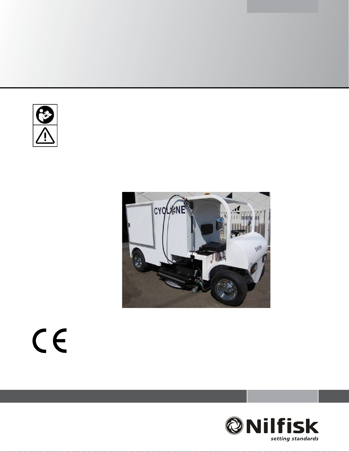
Nilfi sk Cyclone
INSTRUCTIONS FOR USE
ORIGINAL INSTRUCTIONS
10/09
FORM NO. 56041819
Printed in USA
MODEL: 56380676
English

2 / ENGLISH
TABLE OF CONTENTS
Page
Cautions and Warnings Symbols..................................................3
Safety Recommendations ............................................................4
Battery Safe Handling Guidelines ................................................. 5
Introduction ................................................................................... 5
Parts and Service ......................................................................... 5
Nameplate .................................................................................... 5
Uncrating the Machine .................................................................. 5
Know Your Machine...............................................................6 – 9
General Information .............................................................10 – 15
Preparing the Machine for Use .........................................16 – 18
Prior to Start-up ...........................................................................16
Filling Water / Reclaim Tanks ..............................................17 – 18
Fuel ..............................................................................................18
Operating the Machine ......................................................19 – 21
Start-up ........................................................................................19
Cleaning Operation ......................................................................19
Cleaning With the Wand or Curb Cleaner ...................................20
Four Wheel Steering ....................................................................21
After Using the Machine ...................................................22 – 24
Draining/Filtering/Cleaning Reclaim Tanks ..................................22
Draining The Stainless Steel Filter Housing ........................23 – 24
Maintenance .......................................................................25 – 29
Maintenance Schedule ........................................................25 – 27
Changing Spray Tips ...................................................................28
Temperature On Water Temperature Controller ..........................28
Hydraulic Filter Pop-Out Indicator ...............................................29
Troubleshooting ................................................................30 – 32
Heater / Burner System ...............................................................30
Electrical System .........................................................................30
Filtration System ..........................................................................31
Hydraulic System .........................................................................31
Engine System ............................................................................31
High Pressure Water System ......................................................32
Cyclone Deck ..............................................................................32
Technical Specifi cations ...........................................................33
2 - FORM NO. 56041819 - Nilfi sk Cyclone
ENGLISH / 3
READ ALL INSTRUCTIONS BEFORE USING
CAUTION AND WARNING SYMBOLS
Nilfi sk uses the symbols below to signal potentially dangerous conditions. Always read this information carefully and take the necessary steps to
protect personnel and property.
GENERAL SAFETY INSTRUCTIONS
Specifi c Cautions and Warnings are included to warn you of potential danger of machine damage or bodily harm.
DANGER!
THIS SYMBOL IS USED TO WARN OF IMMEDIATE HAZARDS THAT WILL CAUSE SEVERE PERSONAL INJURY OR DEATH.
* This machine emits exhaust gases (carbon monoxide) that can cause serious injury or death; always provide adequate ventilation when
using machine.
WARNING!
THIS SYMBOL IS USED TO CALL ATTENTION TO A SITUATION THAT COULD CAUSE SEVERE PERSONAL INJURY.
* This machine shall be used only by properly trained and authorized persons.
* While on ramps or inclines, avoid sudden stops when loaded. Avoid abrupt sharp turns. Use low speed down hills.
High speed operation is designed only for use on level surfaces.
* To avoid hydraulic oil injection or injury always wear appropriate clothing and eye protection when working with or near hydraulic system.
* Turn the key switch off (O) and disconnect the batteries before servicing electrical components.
* Never work under a machine without safety blocks or stands to support the machine.
* Do not dispense fl ammable cleaning agents, operate the machine on or near these agents, or operate in areas where fl ammable liquids exist.
* Ear plugs or other hearing protection devices are mandatory. The engines, pumps, and Cyclone Cleaning Head all produce decibel levels
high enough to cause hearing loss.
CAUTION!
THIS SYMBOL IS USED TO CALL ATTENTION TO A SITUTION THAT COULD CAUSE MINOR PERSONAL INJURY OR DAMAGE TO THE
MACHINE OR OTHER PROPERTY.
* This machine is only approved for hard surface use.
* This machine is not suitable for picking up hazardous dust.
* When operating this machine, ensure that third parties (particularly children) are not endangered.
* Before performing any service function, carefully read all instructions pertaining to that function.
* Do not leave the machine unattended without fi rst turning the key switch off (O), removing the key and applying the parking brake.
* Turn the key switch off (O) and remove the key before opening any access panels.
* Take precautions to prevent hair, jewelry, or loose clothing from becoming caught in moving parts.
* Before use, all doors and hoods should be properly latched.
* Do not use on surfaces having a gradient exceeding that marked on the machine.
NOTES:
Pay attention to the yellow decals on this machine.
If you have any questions, contact your supervisor or your local Nilfi sk Industrial Dealer.
Should your machine malfunction, do not attempt to correct the problem.
Only a trained company mechanic or an authorized Nilfi sk Dealer Service person shall make repairs to this equipment.
The maximum rated incline during operation in 24”.
Reference the separately supplied engine manufacturer’s maintenance and operator manuals for more detailed engine specifi cation and
service data
SAVE THESE INSTRUCTIONS
FORM NO. 56041819 - Nilfi sk Cyclone - 3
4 / ENGLISH
SAFETY RECOMMENDATIONS
Before Operating Equipment
Equipment and Clothing
Standard Practice & Procedures
This information was prepared to aid in the identifi cation of potentially unsafe conditions when using high-pressure waterblast equipment. These
practices describe how to use high-pressure waterjets for cleaning hard surfaces. These practices do NOT replace the training necessary to
operate and maintain high-pressure waterjet systems. It should be noted that other potential hazards might exist which have not been mentioned
in this manual.
BEFORE OPERATING EQUIPMENT:
Before operation of this equipment, it is important that you read the Owner’s Manual for each of the component parts installed in your machine. It
is especially important to read and understand all of the safety information included in the manuals. Failure to do so could result in damage to the
equipment, serious injury or death to the operator and may void any and all warranties associated with this equipment.
WARNING!
This equipment has:
MOVING PARTS at HIGH RATES OF SPEED
VERY HOT WATER
HIGH PRESSURE WATER
DIESEL FUEL
In all cases, Nilfi sk products are sold with the understanding that the purchaser agrees to THOROUGHLY TRAIN ALL OPERATING AND
MAINTENANCE PERSONNEL IN THE CORRECT AND SAFE OPERATION AND MAINTENANCE OF THE CYCLONE SYSTEM.
WARNING!
Do NOT attempt to change Original Equipment Manufacturer (OEM) parts or equipment. Use of non-OEM parts could result
in damage to the equipment, serious injury or death to the operator and may void any and all warranties associated with this
equipment.
EQUIPMENT & CLOTHING
1 Ear plugs or other hearing protection devices are mandatory. The engines, pumps, and Cyclone Cleaning Head all produce decibel levels
high enough to cause hearing loss.
2 Leather gloves should be worn at all times. The Cyclone SYSTEM uses 160°F water. High-pressure and return hoses and couplings get hot
enough to burn you.
3 Safety glasses are recommended when operating the Cyclone System.
4 Long pants are recommended when operating the Cyclone System.
STANDARD PRACTICE & PROCEDURES
1 After the NILFISK CYCLONE has come to a complete stop, turn off the engine and apply parking brake. Never leave the NILFISK CYCLONE
engine running unattended.
2 A strong vacuum is formed from the rotation of the Cyclone cleaning head. Therefore, all surface plates such as manhole covers, utility
access covers and large debris must be secured, removed or avoided during the cleaning process.
3 All surfaces should be swept prior to operating the Nilfi sk Cyclone, hard surface cleaner.
4 The Nilfi sk Cyclone is not designed to pick up particulate matter such as sand.
WARNING!
These items could cause extensive and costly damage to the blades and spray bars and serious injury or death to the operator.
1 Always turn off the engine before fueling.
2 Never point the hand-held spray gun at yourself or another person. Water coming out of the gun is at a high enough pressure to cause injury
or death.
3 This equipment should not be used without consulting all applicable standards, guidelines, or recommendations of the United States
Occupational Safety and Health Administration (OSHA), the American Society of Testing Materials (ATSM), the National Standards Institute
(ANSI), and the instructions, recommendations and standards of Nilfi sk. Nilfi sk does not guarantee that the practices described and the
recommendations contained in this manual will prevent harm or injury, even when such equipment is properly used in conformity with the
recommended practices. In the event of bodily injury, nothing in this manual should substitute for proper medical care.
4 - FORM NO. 56041819 - Nilfi sk Cyclone
ENGLISH / 5
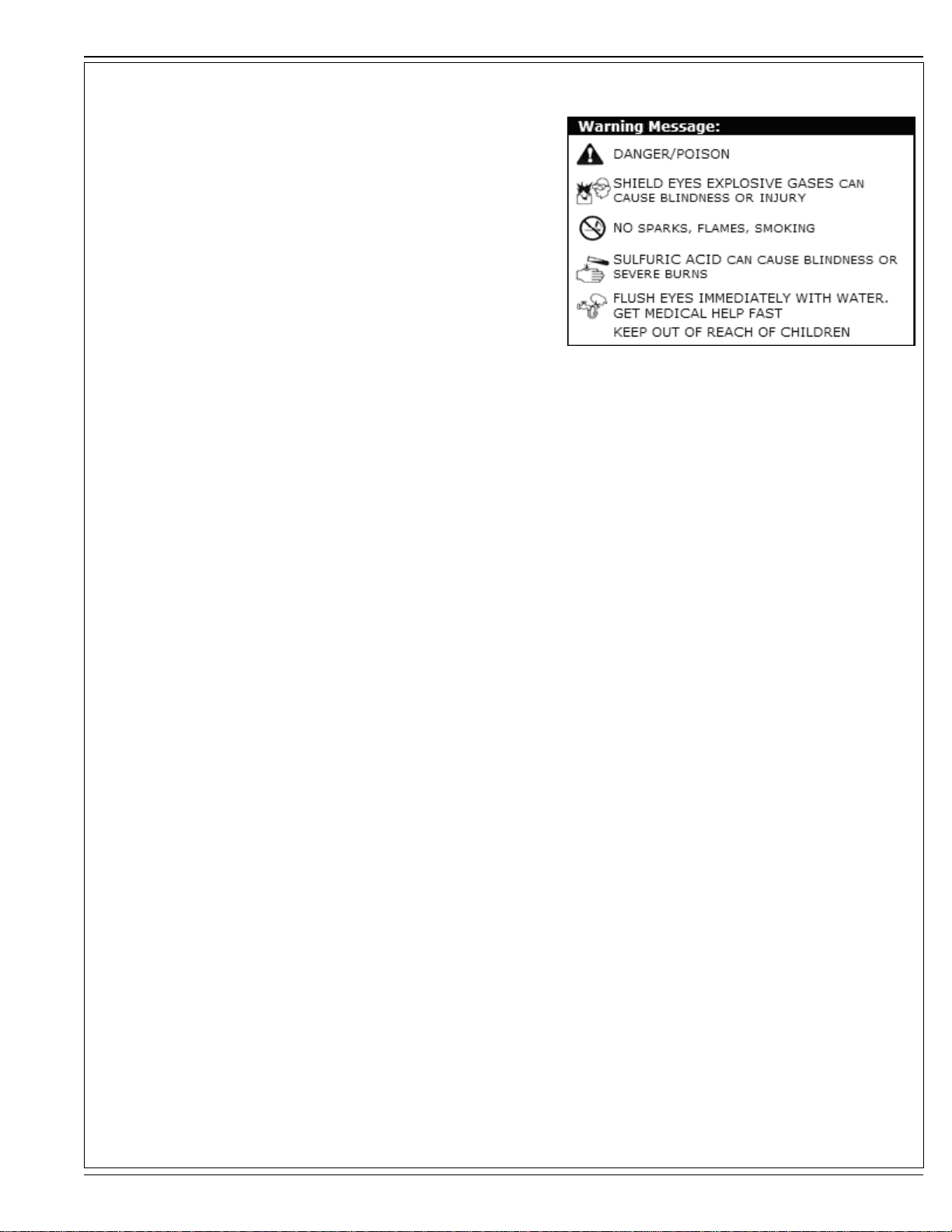
BATTERY SAFE HANDLING GUIDELINES FIGURE 1
Always wear proper eye, face and hand protection when working with battery
Never lean over battery while boosting, testing, or charging
Exercise caution when working with metallic tools or conductors to prevent short circuits
and arcing
Keep terminals protected to prevent accidental shorting
Replace any battery that has signs of damage to the terminals, case, or cover
Install battery in a ventilated area for operation and during charging
DO NOT ADD WATER TO THE OPTIMA BATTERY
Battery Maintenance
The OPTIMA battery is truly maintenance free. When charged properly you will not have
to worry about leaking, corrosion, or gassing. Periodically inspect your battery terminal
connections to ensure they are clean, snug, and protected from the elements.
Open circuit voltage (OCV) and storage:
OCV: 34 >12.8 volts
(for a fully charged battery)
D34 >13.0 volts
(for a fully charged battery)
Battery Storage
Because of the high purity lead grid in the OPTIMA battery, it has a self-discharge rate much lower than conventional fl at-plate batteries. This means the OPTIMA
can sit for longer periods retaining enough charge to start your vehicle. Depending on storage temperature, the OPTIMA can usually sit for 8 to 12 months and
start most vehicles.
When possible, store your battery in a cool, dry location. Check the battery voltage every 6 months and charge if it falls below 12.6 volts.
Remember, newer vehicles with on-board electronics such as computers, LCD screens, game systems, GPS units, clocks, etc., require battery power to retain
system memory while the vehicle is parked. If the vehicle is to be stored for long periods you should use a maintenance charger to compensate for this drain. This
charger should be voltage regulated between 13.2 - 13.8 volts, 1 amp maximum. On older vehicles, without electronics, disconnect the battery cables when the
vehicle is not being used for extended periods.
INTRODUCTION
This manual will help you get the most from your Nilfi sk Cyclone. Read it thoroughly before operating the machine.
This product is intended for commercial use only.
PARTS AND SERVICE
Repairs should be performed by Nilfi sk service personnel using Nilfi sk original replacement parts and accessories.
Call Nilfi sk for repair parts or service. Please specify the model and serial number when discussing your machine.
NAME PLATE
The model and serial number of your machine are shown on the nameplate on the machine. This information is needed when ordering repair parts for the
machine. Use the space below to note the model and serial number for future reference.
MODEL _______________________________________________________________
SERIAL NUMBER _______________________________________________________
UNCRATING THE MACHINE
1 Upon delivery, carefully inspect the machine for damage. If damage is evident, contact the trucking company immediately to fi le a freight damage claim.
2 Read the instructions in the “Preparing the Machine For Use” section of this manual. Read the instructions in the “Operating Controls” and “Operating the
Machine” sections of this manual before starting the engine.
3 Remove the binding straps.
4 Verify the engine oil level, engine coolant level, hydraulic oil level and the high pressure pump oil level.
5 Verify suffi cient diesel fuel is in the fuel tank for transporting the machine out of the shipping container.
6 Keep your foot lightly on the brake pedal until the machine is out of the container. Slowly drive the NILFISK CYCLONE out of the shipping container.
FORM NO. 56041819 - Nilfi sk Cyclone - 5
6 / ENGLISH
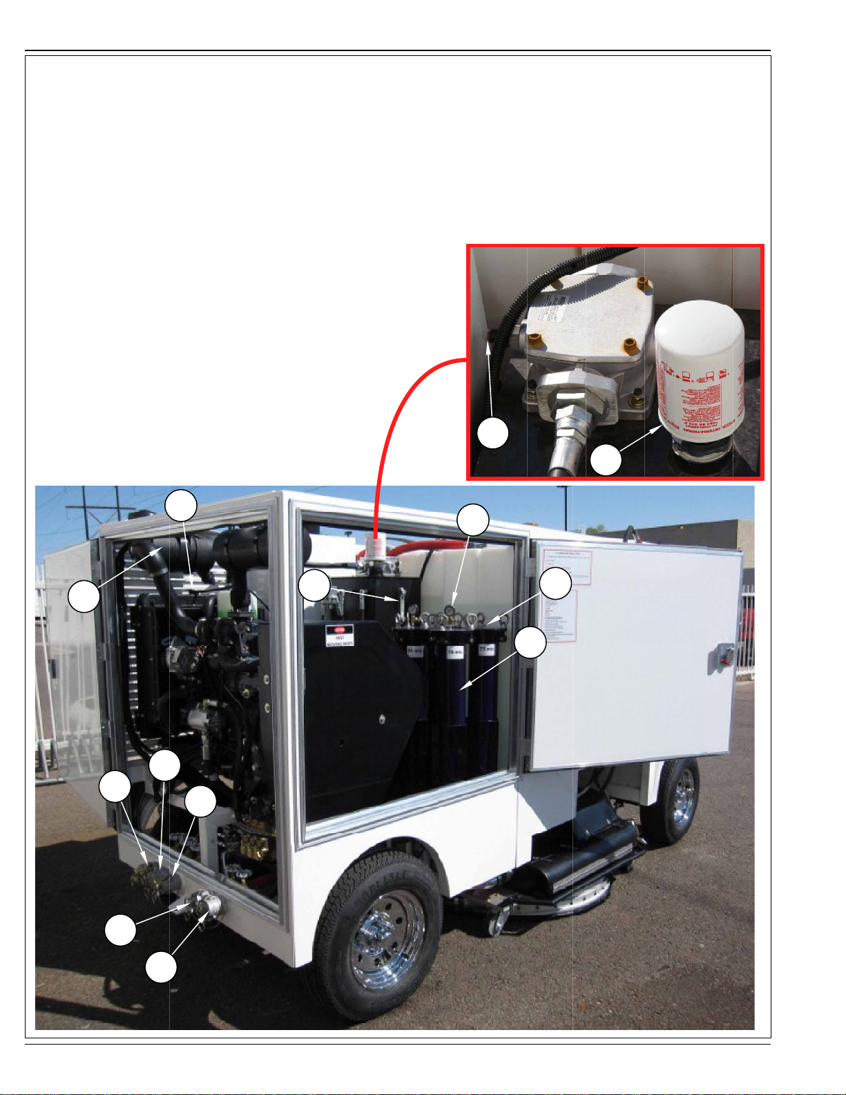
KNOW YOUR MACHINE
As you read this manual, you will occasionally run across a bold number or letter in parentheses, i.e., (2). These numbers refer to an item shown
on these pages unless otherwise noted. Refer back to these pages whenever necessary to pinpoint the location of an item mentioned in the text.
NOTE: Refer to the service manual for detailed explanations of each item illustrated on these pages.
1 Engine Air Filter
2 Radiator Cap
3 Hydraulic Level Gauge
4 Hydraulic Filter Pop-Out
5 Hydraulic Breather Filter
6 Water Filter Pressure Gauges
7 Bleed Valves
8 Water Filters
9 Reclaim #1 Drain
10 Reclaim #2 Drain
11 Reclaim #3 Drain
12 Filter Drain
13 Fresh Water Drain
4
5
2
6
3
7
1
8
10
9
11
12
13
6 - FORM NO. 56041819 - Nilfi sk Cyclone
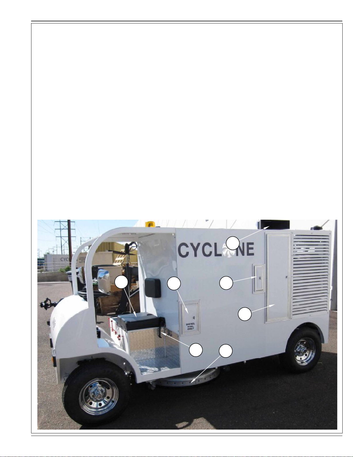
KNOW YOUR MACHINE
14 Operator Seat
15 Fuel Access Door
16 Seat Belt
17 Cyclone Cleaning Head
18 Burner Exhaust
19 Hot Water Coil, Burner, Fuel Filter Access Door
20 Remote Water Fill Connection
ENGLISH / 7
14
15
16
18
20
19
17
FORM NO. 56041819 - Nilfi sk Cyclone - 7
8 / ENGLISH
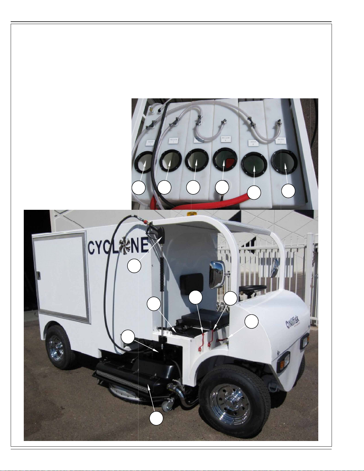
KNOW YOUR MACHINE
21 Cyclone Breather Tubes
22 Cleaning Wand
23 Parking Brake
24 Wand Control Lever
25 Curb Cleaner Lever
26 Recovery Tank / Debris Tray
27 Fresh Water Tank #1
28 Reclaim Tank #1
29 Reclaim Tank #2
30 Reclaim Tank #3
31 Fresh Water Tank #2
32 Fresh Water Tank #3
33 Cyclone Pressure Control Lever
21
27
22
23
28
29
24
30
25
31
33
32
8 - FORM NO. 56041819 - Nilfi sk Cyclone
26
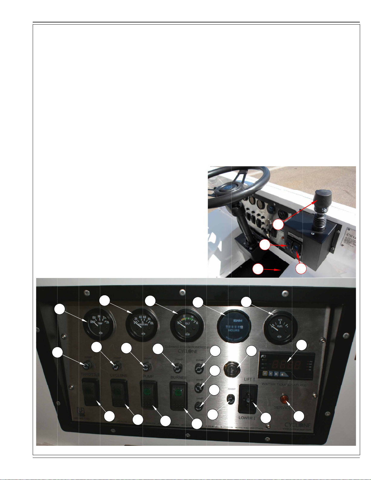
KNOW YOUR MACHINE
A Engine Coolant Temp Gauge
B Engine Oil Pressure Gauge
C Electrical System Volt Meter
D Hour Meter
E Fuel Gauge
F 20 Amp Fuse (throttle)
G 20 Amp Fuse (cyclone)
H 20 Amp Fuse (pump)
I 20 Amp Fuse (burner)
J 20 Amp Fuse
K 8 Amp Fuse
L 2 Amp Fuse
M Ignition Switch
N Water Temperature Controller
O Throttle Switch
P Cyclone Switch
Q Pump Switch
R Burner Switch
S 20 Amp Fuse
T Deck Raise/Lower Switch
U Hi/Lo Water Level Indicator Light
V 2 Wheel / 4 Wheel Steer Switch
W Directional Control Lever
X Brake Pedal
Z high/low speed switch
ENGLISH / 9
W
V
X
B
C
D
E
Z
A
F
G
H
I
J
M
N
K
L
O
P
Q
S
T
U
R
FORM NO. 56041819 - Nilfi sk Cyclone - 9
10 / ENGLISH
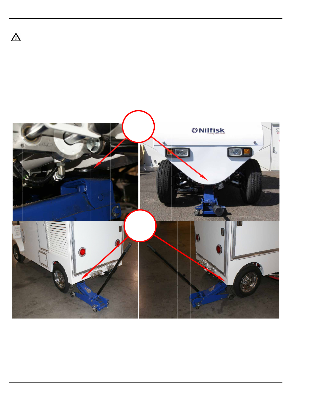
JACKING THE MACHINE
CAUTION!
Never work under a machine without safety stands or blocks to support the machine.
• When jacking the machine, do so at three designated locations: The front cross-member between the two front tires, and at each side of the
rear of the chassis.
• When positioning the jack, take care to avoid hitting the hydraulic cylinders or sense switch!
FIGURE 2
A
B
10 - FORM NO. 56041819 - Nilfi sk Cyclone
ENGLISH / 11
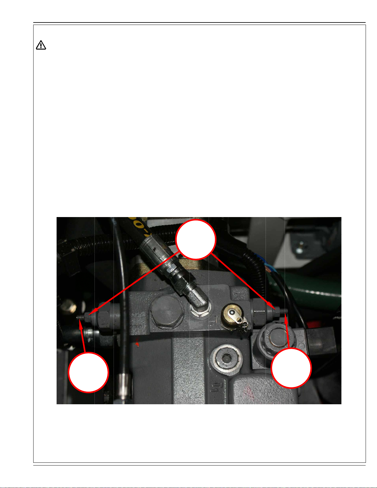
TOWING OR PUSHING THE MACHINE
CAUTION!
IF THE TOW VALVES ARE NOT PROPERLY ADJUSTED, DAMAGE TO THE HYDRAULIC SYSTEM WILL RESULT.
DO NOT TOW THE MACHINE FASTER THAN A WALKING PACE.
TOW OPTIONS ARE MEANT TO BE USED FOR A SHORT TIME ONLY. DO NOT USE FOR AN EXTENDED PERIOD OF TIME.
Tools Required
13 MM box end wrench
4 mm Allen Wrench
TOW VALVE SETTING
1) To actuate the tow valves, loosen the two lock nuts (A).
2) Turn the two Allen screws (B & C) six turns clockwise. Be accurate, as the secondary function of these valves is the high pressure regulation.
3) To disengage, turn the screws counter-clockwise until the exact position of the screws are reset. Torque the locknut to 5ft.lb. (7 Nm)
4) Recheck the high pressure relief settings after tow valves have been repositioned!
A - 13MM Lock Nut
B - 4mm Allen Tow Valve / High Pressure Relief A
C - 4mm Allen Tow Valve / High Pressure Relief B
FIGURE 3
A
B
C
FORM NO. 56041819 - Nilfi sk Cyclone - 11

12 / ENGLISH
B
PREP FOR TRANSIT
CAUTION!
NEVER USE CHAINS OR LOAD BINDERS TO SECURE THIS MACHINE. When tying down this
machine, only cloth ratchet straps with a minimum capacity of 10,000 lbs are recommended (see picture
at right). Be sure to note the proper load rating and tensile strength of the straps to be used. The Nilfi sk
Cyclone weighs around 4000lbs. dry, and around 6000lbs. full of water. All four corners of the machine
shall be secured.
1 Carefully load the machine into the desired position on the trailer.
2 Lower the cleaning head (A) (fi gure 4), and apply the parking brake (B) (fi gure 5).
FIGURE 4
A
FIGURE 5
B
12 - FORM NO. 56041819 - Nilfi sk Cyclone

ENGLISH / 13
PREP FOR TRANSIT
3 Locate the tie down rings (A) at the rear of the machine. Use tie down straps hooked into these rings and then hooked to a secure position
on the trailer to the rear of the machine and tighten the straps.
FIGURE 6
WARNING!!
DO NOT allow ANY strap to make contact with the body or doors of the machine!!
FORM NO. 56041819 - Nilfi sk Cyclone - 13

14 / ENGLISH
PREP FOR TRANSIT
4 At the right front corner of the machine, locate the tie down ring (A) (fi gure 7).
FIGURE 7
5 Hook a tie down strap into the ring. Hook the strap to a tie down point on the trailer forward of the machine, and tighten the strap.
WARNING!!
DO NOT allow ANY strap to make contact with the body or doors of the machine!!
14 - FORM NO. 56041819 - Nilfi sk Cyclone

PREP FOR TRANSIT
6 At the left front corner of the machine, locate the tie down ring (B) (fi gure 8).
FIGURE 8
ENGLISH / 15
7 Hook a tie down strap into the ring. Hook the strap to a tie down point on the trailer forward of the machine, and tighten the strap.
WARNING!!
DO NOT allow ANY strap to make contact with the body or doors of the machine!!
FORM NO. 56041819 - Nilfi sk Cyclone - 15

16 / ENGLISH
PREPARING THE MACHINE FOR USE
1 Check the tires for pressure, abnormal wear patterns, and any foreign objects.
2 Make sure the parking brake is functioning correctly
3 Check the lights
4 Check fl uid levels on engine and pumps
5 Check belts and hoses on engines and pumps.
6 Verify seat belt latch is functional
PRIOR TO START-UP
1 See Figure 9. Prior to start up, check the cleaning head. Check the outer 8 bolts (A) on the protective shield for excessive wear. Any wear
requires a bolt change. Also, make sure all bolts are securely tightened before operating.
2 Check pressure tips and replace as necessary.
FIGURE 9
WARNING!
A
Failure to check the Cyclone shield bolts and pressure tips can result in damage to the blades, spray bars and possible operator
injury.
WARNING!
MAKE SURE CLEANING HEAD IS SUPPORTED BEFORE CHANGING SPRAY TIPS
16 - FORM NO. 56041819 - Nilfi sk Cyclone

ENGLISH / 17
PREPARING THE MACHINE FOR USE
FILLING WATER/RECLAIM TANKS
1 See Figure 10. Put the water hose in Reclaim Tank #2 (D) and fi ll Reclaim Tanks #1, #2 & #3 (B) to 1” from the top. NOTE: Once tank #2
fi lls water will automatically fl ow into Reclaim #1 (C) and Reclaim #3 (E).
2 Start the engine and set Throttle Switch (O) to the ON position.
3 Open the valves on top of each fi lter housing. After the water begins to fl ow close the valves.
4 Keep the Throttle Switch (O) ON until the fi lter pump turns OFF or until water stops fl owing into the clean water tanks (A).
5 Fill the Clean Water Tanks to 6” from the top.
FIGURE 10
A
C
D
B
A
E
FILLING WATER/RECLAIM TANKS WITH REMOTE FILL
1 See Figure 10. Connect garden hose to Remote Fill Connection (F) and rotate
Remote Water Fill Valve (G) to the UP position for reclaim tanks.
2 Turn on garden hose and fi ll reclaim tanks to 1” from the top then turn hose off. Start
the engine and set Throttle Switch (O) to the ON position.
3 Open the valves on top of each fi lter housing. After the water begins to fl ow close the
valves.
4 Keep the Throttle Switch (O) ON until the fi lter pump turns OFF or until water stops
fl owing into the clean water tanks (A).
5 Rotate Remote Water Fill Valve (G) to the DOWN position, turn garden hose ON and
fi ll the Clean Water Tanks to 6” from the top. Turn garden hose OFF.
G
F
FORM NO. 56041819 - Nilfi sk Cyclone - 17

18 / ENGLISH
PREPARING THE MACHINE FOR USE
FILLING WATER/RECLAIM TANKS (CONTINUED)
6 See fi gure 11. The high-pressure pump (A) is located to the rear and below the engine bell housing.
7 Once water fl ows through this valve with no air, the pump supply is primed.
FIGURE 11
A
WARNING!
CAUTION: DO NOT OVERFILL RECLAIM TANKS. WATER CAN SPILL ONTO THE GROUND, which defeats the total recovery
principal of this machine.
FUEL
The burner and engine use DIESEL FUEL. The diesel fuel tank is located on the left side of the NILFISK CYCLONE.
18 - FORM NO. 56041819 - Nilfi sk Cyclone

ENGLISH / 19
OPERATING THE MACHINE
START-UP
WARNING!
Operating the pump without suffi cient water in the tank will void the warranty on the pump and any other equipment damaged due to
this action.
1 Turn the key to the “ON” and “START” positions on the control panel. Once the engine starts, allow engine to warm up for 3 minutes before
increasing RPM.
2 To prime the water fi lters:
Rotate the air bleed valves on top of all 4 fi lter housings to “OPEN” position.
With the engine running and the pump fl oat control switch in the “UP“ position in Reclaim #3, water will fl ow into the fi lter housings
Run the engine until water fl ows through each valve.
Close each valve as water starts to fl ow.
Note: This fi lter priming process must be done after every fi lter cleaning, before resuming cleaning.
Failure to bleed the fi lters will cause a decrease in cleaning time.
CLEANING OPERATION
WARNING!
Make sure that all fl oor grates and covers are secured to the fl oor, as the Cyclone Cleaning Head could project any loose objects that
could cause physical injury and property damage. Do not operate on loose or broken concrete or asphalt as damage to the surface
could occur, as well as damage to the cleaning head itself.
1 Drive the unit to the area to be cleaned, and ensure the engine water temperature is 130 degrees or above before cleaning.
2 Survey the area to be cleaned. Make sure it is free of sharp objects that could damage the tires.
3 The cleaning results will be improved if the area is swept of debris before cleaning.
4 Switch the throttle to high speed, move the speed control level forward. After forward motion starts, turn on the Cyclone switch, then the
Pump switch, lastly the Burner switch. Operate the unit for 3 to 4 minutes to allow the cleaning water temperature to rise.
Note: To clean without heat, simply leave the burner switch off.
5 This unit must be kept moving whenever the high pressure pump is on; standing still will cause the surface to become scarifi ed.
6 Depending on the severity of the dirt/oil/grease on the surface being cleaned, you may need to decrease your speed and double scrub very
soiled areas. (Cleaning the least soiled area fi rst will extend the duration of cleaning time before debris fi lters need to be serviced.)
7 Once you have cleaned as much area as desired, turn the heater off. It is recommended to run the pump for a few minutes WITHOUT HEAT
after your cleaning is complete. This will run fresh water through the burner to allow it to cool before turning off the system.
8 Lastly, turn off the pump, keeping the Cyclone spinning to recover residual water.
FORM NO. 56041819 - Nilfi sk Cyclone - 19

20 / ENGLISH
OPERATING THE MACHINE
CLEANING WITH THE WAND (SPRAY GUN) OR CURB CLEANER
FIGURE 12
A
B
CAUTION!
Do not move the selector levers with the high pressure switch turned on. Never point the spray wand or the curb cleaner at a person
- injury may result.
1 Place the control valve handle in either the Wand (A) or the Curb Cleaner (B) position, (Figure 12)
2 To pick up water with the cyclone when using the curb cleaner or the wand, leave the cyclone head down and the cyclone switch in the “ON”
position.
3 To return to cyclone head cleaning, turn off the high pressure pump and return the levers to the upright position.
20 - FORM NO. 56041819 - Nilfi sk Cyclone

ENGLISH / 21
OPERATING THE MACHINE
FOUR WHEEL STEERING / HIGH SPEED OPERATION
To engage the Four Wheel Steering System, switch from 2ws to 4ws. (4ws mode will require more effort to turn the wheels - this is normal).
If the NILFISK CYCLONE begins to “crab steer” while in 4 Wheel Mode, simply switch to 2 Wheel Steer and then back to 4 Wheel Steer (A).
To engage in high speed steering , simply switch the high / low switch (B) to the high position.
FIGURE 13
A
B
FORM NO. 56041819 - Nilfi sk Cyclone - 21

22 / ENGLISH
AFTER USING THE MACHINE
DRAINING/FILTERING/CLEANING THE RECLAIM TANK
1 Tanks should be drained and cleaned at the end of each shift.
2 Run the engine on the Cyclone Head to pump as much water and waste out of the waste tank as possible, then turn off the Cyclone and the
engine.
3 Check the waste tank on the Cyclone Cleaning Head to make sure there are no obstructions.
4 If there is debris and the discharge port is plugged, water will not pump out and the tank will overfl ow.
5 To clean the bottom of the tank, use a putty knife to scrape the debris into an empty tub or bucket.
6 Make sure there is nothing inhibiting water from fl owing out of the discharge port at the base of the tank.
7 Close the top of the tank.
WARNING!
The power plant engine and pump should be turned off while draining the tanks.
FIGURE 14
RECLAIM #1 RECLAIM #2 RECLAIM #3 Filter Drain Fresh Water
1 To drain the tanks, identify each of the connections at the rear of the machine (Figure 14)
2 Attach the 1 1/2” drain hose to the outlet drain that is all the way to the left at the back of the NILFISK CYCLONE. This is attached to
Chamber #1 in the reclaim tank.
3 Make sure the connection is securely attached
4 At the other end of the drain hose, securely attach the 100-micron bag fi lter with a wire-tie.
5 Place the end of the hose over the sanitary sewer opening or into a transport or de-watering tank.
6 The drain valves for each hose connection located just inside the back of the NILFISK CYCLONE (fi gure 14).
7 Open the drain valve on the NILFISK CYCLONE by unscrewing the blue handle. This releases the water from Chamber #1 in the reclaim
tank.
8 Drain until the chamber is empty or the bag fi lter is full and is no longer allowing water to fl ow through it.
NOTE: You may need to open the cover on the tank to allow air into the tank.
9 If the chamber will not drain because too many solids have settled at the base of the chamber (sand, dirt, etc.), you need to unclog the
drain. To do this, use the handle of a broom or shovel and insert it into the top of the tank and GENTLY prod the sediment at the base of the
chamber.
10 If you need to change the bag fi lter before the chamber is empty, turn off the drain valve. Do this before removing and replacing the fi lter.
11 Attach the new bag fi lter and resume draining of Chamber #1.
12 When Chamber #1 is empty, rinse out the chamber using a water hose. When fi nished rinsing, turn off the drain valve and move the drain
hose to the next outlet drain.
Note: Chamber #2 is the MIDDLE outlet; Chamber #3 is the outlet on the FAR RIGHT.
13 Repeat the draining procedures until all three chambers of the reclaim tank are drained and cleaned.
14 Inside Chamber #3 are two stainless steel fi lter elements. They must be cleaned during each service of the unit. Failure to clean elements
will slow down fi ltration process and may cause damage to fi lter pump.
15 Do not drain the clean water tank until you have drained and cleaned the fi lters.
22 - FORM NO. 56041819 - Nilfi sk Cyclone

ENGLISH / 23
AFTER USING THE MACHINE
SERVICING THE STAINLESS STEEL FILTERS & HOUSINGS
1 Filters should be drained and cleaned at the end of each shift.
2 See Figure 15. The stainless steel fi lters are located on the right side of the NILFISK CYCLONE and are inside the PURPLE housings.
NOTE: The fi lters are plumbed in series with 75-micron and 30-micron stainless steel elements. After cleaning, these fi lters MUST be replaced in
the same fi lter housing they came out of. Failure to do so will cause the fi lters to stop working and back up the water in the reclaim tank.
75-Micron: Next to door
30-Micron: Closest to the hydraulic tank
3 Attach the 1 1/2” drain hose to the outlet drain second to last on FAR RIGHT at the back of the NILFISK CYCLONE, attached to the blue
hand valve.
4 At the other end of the drain hose, attach the 100-micron bag fi lter securely using a wire-tie.
5 Place the end of the hose over the sanitary sewer opening or into a transport or de-watering tank.
FIGURE 15
FORM NO. 56041819 - Nilfi sk Cyclone - 23

24 / ENGLISH
AFTER USING THE MACHINE
WARNING!
There must be suffi cient water in the clean water tank to clean the fi lters. Make sure the tank is at least half full before proceeding with the fi lter
cleaning.
STAINLESS STEEL FILTER MAINTENANCE
6 See Figure 16. The valves for the fi lters are located in front of the right rear tire, under the NILFISK CYCLONE.
7 Close Valve (A) to stop fl ow of water from reclaim tank #3 to fi lter housing.
8 Open Valve (B) to drain the fi lters (present on some models)
9 When the fi lter housings are drained, clean the stainless steel fi lters.
10 Use a long handled screwdriver to loosen the eyelets on the top of the fi lters.
Note: The caps are spring loaded.
11 Remove caps by lifting straight up. (Caution: the fi lter caps are under spring pressure)
FIGURE 16
B
12 See Figure 17. Lift the stainless steel fi lter straight up and out of the housing.
13 Rinse out the fi lter housing using a water hose and let it drain through the sock fi lter.
14 Inspect “O” rings on bottom of fi lters for wear or breaks. Replace if missing or worn.
15 Clean the fi lters with the high pressure wand next to the Cyclone Head to contain water.
16 Replace the fi lters in the housings and recap the
housings.
17 Open the left hand valve (A) to resume water fl ow from
reclaim tank #3 through the fi lters.
A
FIGURE 17
24 - FORM NO. 56041819 - Nilfi sk Cyclone

MAINTENANCE
Daily Weekly Monthly Annually
Cyclone System
Cyclone Belt Tension and Condition
Rebuild High Pressure Union @ 150-200 hrs X
Grease Bottom Spindle Bearing X
Grease Top Spindle Bearing X
Grease Return Pump Bearing X
Grease Return Pump Idler Bearing X
Cyclone Brush Skirting condition @ 40hrs X
Check Cyclone High Pressure Tips & Bolts @ 15hrs X
Check Cyclone Deck Cables for Wear or Abrasion X
Check Cyclone Deck Casters and Blade/Bars X
Engine System
Check Engine Oil X
Check Fuel Filter X
Check Air Filter & Inlet Tube Service @ 500hrs XX
Check Indicator Lamps X
Change Engine Oil & Filter @ 250 Hours X
Replace Fuel Filter X
Clean Crankcase Vent Tube X
Check Engine RPM X
Check Belt Tensioner And Belt Wear X
Check Engine Ground Connection X
Check Engine Mounts X
Service Battery Connections X
Check Cooling System X
Pressure Test Cooling System X
Flush Cooling System @ 1000 hrs or Annually X
Test Thermostat X
Replace Belt X
Clean Radiator Fins X
X
ENGLISH / 25
FORM NO. 56041819 - Nilfi sk Cyclone - 25

26 / ENGLISH
MAINTENANCE
Daily Weekly Monthly Annually
Low Pressure Water System
Check For Leaks & Verify Service Light Operation X
Clean 30 and 75 Micron Filters X
Clean Debris Tray and Screen X
Rinse Out Tanks & Check Seals X
Recovery Hose from Tank to Pump Cyclone Deck X
High Pressure Water System
Check Oil Level in High Pressure Pump X
Check For Oil / Water Leaks X
Verify Pressure X
Replace High Pressure Pump Packing @ 150-200 hrs X
Oil Change High Pressure Pump @ 500 hrs X
Clutch Condition & Pressure Switch X
Wand and Curb Sprayer Condition X
Drive System
Check for Leaks X
Check Tire Condition and Pressure X
Steering System
Check for Loose Components X
Check Tire Wear for Alignment Issues X
Verify Rear Steering Operation X
Wheels And Axles Grease @ 40hrs X
Fuel System
Drain Water from Fuel Separator X
Change Fuel Filter for Burner X
Burner System
Check For Leaks X
Check Flame Adjustment X
Check Temperature Adjustment X
Filter pump
Check clutch operation X
Check Belt Tension X
26 - FORM NO. 56041819 - Nilfi sk Cyclone

MAINTENANCE
Daily Weekly Monthly Annually
Braking System
Check For Leaks X
Verify Fluid Level X
Check For Brake Wear and Condition X
Hydraulic System
Check For Leaks X
Verify Pressures X
Verify Lift Lower Switch Operation X
Verify Cyclone Pump Operation X
Verify Steering Select Valve Operation 4ws X
Clean Hydraulic Cooler X
Lubricate Overhung Load Adaptor @ 40hrs X
Replace Return Filter @ 500 hrs X
Replace Hydraulic Breather @ 500hrs X
Hydraulic Fluid Sample Test @ 1000 hrs X
Safety Items
Verify Seat Belt Latch Operation X
Warning System Lights, Backup, Alarm X
Service Brake Operation / Parking Brake X
ENGLISH / 27
FORM NO. 56041819 - Nilfi sk Cyclone - 27

28 / ENGLISH
MAINTENANCE
CHANGING SPRAY TIPS
1 Spray tips should be changed every 8 - 16 hours depending on the severity of the cleaning being done. This can be determined if the
machine is losing pressure due to the tips opening up from excessive wear.
2 Use a 9/16” or 14 mm socket to remove the spray tips from the spray bars. This can be done without removing the protective shield.
3 Wrap the threads of the new tips with a minimum of 5 wraps of Tefl on tape and replace into the spray bars. The slot in the tip must be aligned
in the direction of the spray bar for the system to operate correctly.
WARNING!
Always support the Cyclone head prior to working beneath the deck. When installing new spray tips, they must have a MINIMUM of
5 wraps of Tefl on tape to make sure the stainless steel threads on the tip DO NOT CONTACT the threads of the stainless steel spray
bar. Contact between the two can cause the tip to seize inside the spray bar, and the spray bar will have to be replaced.
TEMPERATURE ON WATER TEMPERATURE CONTROLLER
The temperature setting has been preset to 160 degrees Fahrenheit. The burner will heat the water to this temperature before the fuel supply is
shut off.
FIGURE 18
E
28 - FORM NO. 56041819 - Nilfi sk Cyclone
M
>
^

ENGLISH / 29
MAINTENANCE
HYDRAULIC FILTER POP-OUT INDICATOR
Hydraulic breather should be replaced every 250 hours.
See Figure 19. Indicator (A) will indicate when the hydraulic fi lter needs to be replaced.
Hydraulic fi lter pop-out should be checked daily.
Never operate the Nilfi sk Cyclone with a dirty hydraulic fi lter. Doing so will cause severe system damage and will VOID MANUFACTURER’S
WARRANTY.
FIGURE 19
A
FORM NO. 56041819 - Nilfi sk Cyclone - 29

30 / ENGLISH
TROUBLESHOOTING
Heating / Burner System – Diesel Fired
Problem Probable Cause Remedy
Burner will not light Burner switch not on Turn switch on
Diesel fuel level low Fuel tank level must be above 1/4 full on
gauge. Fill burner tank with #2 diesel or
other approved fuel.
Water pump not on, no water pressure Turn pump switch on
Fuel fi lter plugged Clean and / or tighten fuel fi lter. (Check
fuel pressure)
Burner nozzle dirty Clean nozzle
Overload on burner motor tripped Reset overload, locate and correct
source of overload
Low water pump pressure See high pressure pump systems
troubleshooting
Fuel pump or nozzle stopped Check fuel fi lter and fuel lines. Replace
nozzle
Burner will not light, plus diesel fumes
are emitted from the exhaust port
Burner lights but smokes Incorrect fuel usage Only #2 diesel should be used
Discharge water temperature exceeds
recommended operating temperature
Water sprays out of pressure relief on
burner housing
Discharge water temperature not
reaching maximum operating
temperature
Electrical System
Fuel nozzle partially clogged Replace nozzle of proper size
Excessive soot on coils Clean soot off to improve airfl ow
Improper voltage at burner Check battery and alternator
Temperature controller set too high Adjust the dash-mounted temperature
controller
Water fl ow restricted Clean or replace nozzle of proper size.
De-scale coil and clear obstructions.
Temperature controller set too low Reset temperature controller
Battery voltage low Have battery checked and load test.
Charge if low, and replace if necessary.
Allow water to cool 2 min. before shutting
off engine.
Problem Probable Cause Remedy
No power when key is turned on Battery dead Replace battery
Cables disconnected Reconnect cables
Cables dirty Clean cables
System switches do not operate Burned out fuses Replace fuses.
Burned out fuse Incorrect fuses will cause severe
damage to the directional processors.
Direction control stick does not work Broken wiring Check for shorts or breaks in the wiring
30 - FORM NO. 56041819 - Nilfi sk Cyclone

TROUBLESHOOTING
Filtration System
Problem Probable Cause Remedy
Reclaim tanks foaming over Surface being cleaned had a high
foam surfactant previously applied
High pressure pump shuts off, service
light on dash is lit
Pressure differential between 75 micron
fi lters and 30 micron fi lters is 50 psi or
more
Filters have just been serviced and
service light is on
Filter pump not pumping Float valve in reclaim tank not
Filters have been serviced, but run time
is short
Water coming from breather tube Clogged water return pump hose Clear return line or presweep before
Hydraulic System
Filters need to be serviced or clean
water tanks are low
75 micron fi lters plugged Clean all fi lters, drain and refi ll reclaim
Rubber gasket on bottom of fi lters
is missing, not allowing water to be
pumped through the fi lters
Reclaim tanks are dirty Drain tanks and refi ll with clean water
Water level in clean water tanks is low Refi ll water tanks
operating
Dirt and contaminants on the surface
of tanks and fi lters
Reclaim tanks and spillover hoses dirty Thoroughly clean the reclaim tanks,
Filters are dirty and clogged Clean fi lters
Apply an anti-foam chemical
Clean fi lters, drain reclaim tanks and
refi ll with water
tanks
Remove fi lters and reinstall rubber
gasket
Make sure pump is connected
Clean system more completely
including the fi lters and the fi lter
housings
cleaning.
ENGLISH / 31
Problem Probable Cause Remedy
Hydraulics working, machine won’t move Parking brake on Release brake
Fuse in circuit blown Replace with correct fuse
Low oil level in hydraulic tank Fill to middle of sight glass
Cyclone cleaning head won’t spin Blown fuse Replace fuse
Wiring disconnected at manifold Check and reconnect all wiring
Debris lodged in Cyclone cleaning head Clean debris from cleaning head
Engine System
Problem Probable Cause Remedy
Engine will not start or crank over Battery dead Charge or replace battery
Dirty battery contacts Clean connections
Battery cables disconnected Connect or replace damaged cables
Engine will not start but will crank over Engine power switch is off or defective Check engine power switch
Engine bogs down under load Dirty air fi lters Replace fi lters
Dirty fuel Drain and replace with #2 diesel
Engine overheats Check coolant level Add as necessary
Low oil level Add as necessary
Debris obstructing air fl ow through
radiator
Driving with the parking brake on Release brake
Clean air inlet system
FORM NO. 56041819 - Nilfi sk Cyclone - 31

32 / ENGLISH
TROUBLESHOOTING
High Pressure Water System
Problem Probable Cause Remedy
Pump runs but no spray pressure Water turned off Turn water on
Nozzle is plugged Clean or replace with proper size
Pump dry, needs to be primed Prime high pressure system
Pump runs but has low spray pressure Nozzle not installed Install proper sized nozzle
Excessive leaking from rotating union Replace rotating union
Leaky discharge hose or quick coupler Replace hose, quick coupler, or O-ring in
the quick coupler
Belt slippage Tighten or replace with correct belt
Worn or wrong size nozzle Replace nozzle of proper size
Air leak in inlet plumbing. Reseal fi ttings and inspect inlet hoses for
air leaks
Pump runs but there is erratic, fl uctuating
pressure
Relief valve leaking Excessive pressure and/or spikes System must be operating at or LESS
Stuck inlet or discharge valves Clean out or replace worn valves
Restricted inlet or air entering the inlet
plumbing on the pump
Check fi ttings and hose for airtight seal,
clean inlet strainer screen
than 4500psi.
Pressure relief leaking Excessive pressure Check for plugged Cyclone spray tips.
Cyclone Deck
Problem Probable Cause Remedy
Head leaving water on surface Loose belt, Cyclone spinning too slowly Tighten belts
Foreign objects or debris lodged in head Check outlet ports for obstruction wedged
in blades
Obstruction in discharge tubes Disconnect tubes at head and blow water
or air through tubes to release
Return pump not working Check for plugged pump return line
Deck / cleaning head not down Fully lower cleaning head
Excessive foaming Recovering soap or chemical residue
from previous cleaning methods
Cyclone cleaning head won’t spin Blown fuse Replace fuse
Debris lodged in Cyclone cleaning head Clean debris from cleaning head
Treat surface with Tefl on-based anti-foam
product. Recommend Pool/Spa de-
foamer.
32 - FORM NO. 56041819 - Nilfi sk Cyclone

ENGLISH / 33
TECHNICAL SPECIFICATIONS (as installed and tested on the unit)
Model Nilfi sk Cyclone
Model No. 56380676
Sound Pressure Level (IEC 60335-2-72: 2002 Amend. 1:2005, ISO 11201) dB (A) 91.6
Sound Power Level (IEC 60335-2-72: 2002 Amend. 1:2005, ISO 3744) Lwa 113dB
Total Weight lbs/kg 6000 / 2721
Maximum Wheel Floor Loading (right front) psi / N/mm
Maximum Wheel Floor Loading (left front) psi / N/mm
Maximum Wheel Floor Loading (right rear) psi / N/mm
Maximum Wheel Floor Loading (left rear) psi / N/mm
Engine Nominal Power Kw 44 @ 2700 RPM
Vibrations at the Hand Controls (EN 13059 and ISO 5349-1) m/s2 0.70 m/s
Machine Dimensions LxWxH
Vibrations at the Seat (EN 13059 and EN 1032) m/s2 0.01 m/s
Gradeability
Cleaning 16% (9.9°)
Transport 22% (12.4°)
2
2
2
2
36 / 0.25
35 / 0.24
67 / 0.46
58 / 0.40
2
135” (342.9cm) x 60”(152.4cm) x
77”(195.58cm)
2
FORM NO. 56041819 - Nilfi sk Cyclone - 33


Overenstemmelseserklaering Declaration de conformité Samsvarserklaering
Declaration of conformity Verklaring van overeenstemming Vaatimustenmukaisuusvakuutus
Konformitätserklärung Dichiarazione di conformità Atitikties deklaracija
Declaración de conformidad Vastavussertifikaat Osvědčení o shodě
Atbilstības deklarācija Deklaracja zgodności Certifikát súladu
Megfelelősségi nyilatkozat Försäkran om överensstämmelse
Certifikat o ustreznosti
Modell/ Modèle/ Model/ Malli/ Modelo/ Μοντέλο/ Modelo/ Modelis/Модель: Surface Cleaning machine
Type/ Tyyppi/ Tipo/ Τύπος/ Tüüp/ Tipas/ Tips/ Typ/ Típus/ Тип/ Tip: 4500
D Der Unterzeichner bestätigt hiermit dass die oben erwähnten Modelle gemäß den folgenden Richtlinien und Normen hergestellt wurden.
GB The undersigned certify that the above mentioned model is produced in accordance with the following directives and standards.
DK Undertegnede attesterer herved, at ovennævnte model er produceret i overensstemmelse med følgende direktiver og standarder.
N Undertegnede attesterer att ovennevnte modell är produsert I overensstemmelse med fölgende direktiv og standarder.
E El abajo firmante certifica que los modelos arriba mencionados han sido producidos de acuerdo con las siguientes directivas y
estandares.
I Il sottoscritto dichiara che i modelli sopra menzionati sono prodotti in accordo con le seguenti direttive e standard.
EST Allakirjutanu kinnitab, et ülalnimetatud mudel on valmistatud kooskõlas järgmiste direktiivide ja normidega.
LV Ar šo tiek apliecināts, ka augstākminētais modelis ir izgatavots atbilstoši šādām direktīvām un standartiem.
CZ Níže podepsaný stvrzuje, že výše uvedený model byl vyroben v souladu s následujícími směrnicemi a normami.
SLO Spodaj podpisani potrjujem, da je zgoraj omenjeni model izdelan v skladu z naslednjimi smernicami in standardi.
F Je soussigné certifie que les modèles ci-dessus sont fabriqués conformément aux directives et normes suivantes.
NL Ondergetekende verzekert dat de bovengenoemde modellen geproduceerd zijn in overeenstemming met de volgende richtlijnen en
standaards.
FIN Allekirjoittaia vakuuttaa että yllämainittu malli on tuotettu seuraavien direktiivien ja standardien mukaan.
S Undertecknad intygar att ovannämnda modell är producerad i överensstämmelse med följande direktiv och standarder.
GR Ο κάτωθι υπογεγραμμένος πιστοποιεί ότι η παραγωγή του προαναφερθέντος μοντέλου γίνεται σύμφωνα με τις ακόλουθες οδηγίες
και πρότυπα.
A presente assinatura serve para declarar que os modelos supramencionados são produtos em conformidade com as seguintes
P
directivas e normas.
LT Toliau pateiktu dokumentu patvirtinama, kad minėtas modelis yra pagamintas laikantis nurodytų direktyvų bei standartų.
PL Niżej podpisany zaświadcza, że wymieniony powyżej model produkowany jest zgodnie z następującymi dyrektywami I normami.
H Alulírottak igazoljuk, hogy a fent említett modellt a következő irányelvek és szabványok alapján hoztuk létre.
SK Dolu podpísaný osvedčuje, že hore uvedený model sa vyrába v súlade s nasledujúcimi smernicami a normami.
EC Machinery Directive 98/37/EC EN 12100-1, EN 12100-2, EN ISO 13587, EN 349
EC Low Voltage Directive 73/23/EEC, 93/68/EEC, 06/95/EEC EN 60335-1, EN 60335-2-72
EC EMC Directive 2004/108/EEC EN 55012
EC Outdoor Noise Directive 2000/14/EC
Richard Kotch , General Manager
23.7.2009 Year of Affixing the CE marking 2009
Nilfisk-Advance A/S
Sognevej 25
DK-2605 Brøndby, Denmark
©Nilfisk-Advance Technology, 2009
.pas

Nilfi sk-Advance A/S
Sognevej 25
DK-2605 Brøndby
Denmark
Tel: +45 43 23 81 00
Fax: +45 43 43 77 00
www.nilfi sk-advance.com
 Loading...