

Page 1
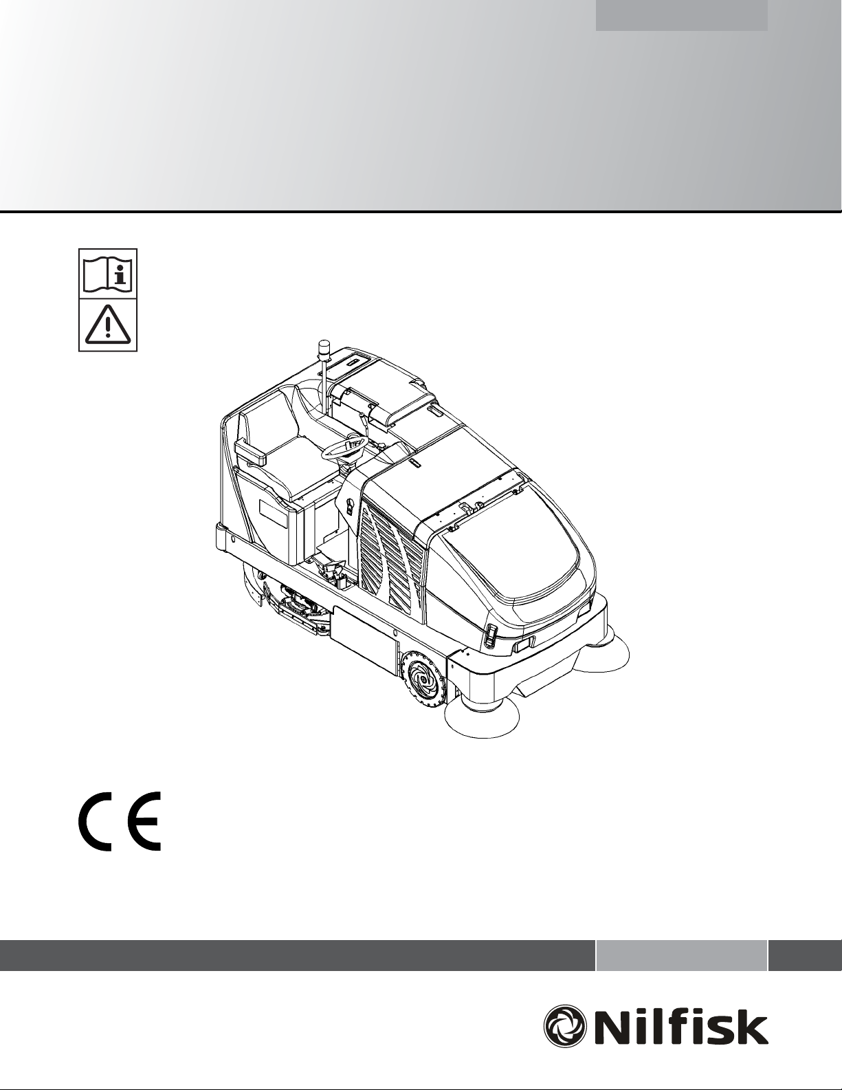
CR 1100, CR 1200
Instructions for Use
Nilfi sk Models: 56303004 (CR 1200), 56303005 (CR 1100 / OBS)
11/08 revised 9/10
FORM NO. 56041776
A-English
Page 2

Page 3

TABLE OF CONTENTS
Page
Introduction ................................................................................... A-4
Parts and Service ........................................................................... A-4
Nameplate ...................................................................................... A-4
Uncrating the Machine .................................................................... A-4
Cautions and Warnings .................................................................. A-5
Consignes de prudence et de sécurité ........................................... A-6
General Information ........................................................................ A-7
Battery Installation ..................................................................A-8 - A-9
Know Your Machine / Operator’s Compartment .............. A-10 – 13
Preparing the Machine for Use
Pre-Operational Checklist ............................................................. A-14
Main Broom .................................................................................. A-14
Scrub Brush Installation ......................................................A-14 - A-15
Filling the Solution Tank ................................................................ A-16
Detergent (EDS) System ....................................................A-16 - A-17
ENGLISH / A-3
Operating the Machine
Sweeping ...................................................................................... A-18
Emptying the Hopper .................................................................... A-18
Scrubbing ..................................................................................... A-19
Emptying the Recovery Tank ........................................................ A-19
After Using the Machine
After Use ....................................................................................... A-20
Maintenance Schedule
Maintenance Schedule ................................................................. A-20
Charging the Battery ..................................................................... A-21
Main Broom Maintenance ............................................................. A-22
Side Broom Maintenance ............................................................. A-23
Squeegee Maintenance ................................................................ A-24
Hopper Dust Control Filter ............................................................ A-25
Hydraulic Oil ................................................................................. A-25
Drive Wheel Gear Case Oil .......................................................... A-26
Lubrication .................................................................................... A-26
Circuit Breaker Location ............................................................... A-26
Troubleshooting ................................................................. A-27 – A-28
Technical Specifi cations ............................................................... A-29
FORM NO. 56041776 - CR 1100, CR 1200 - A-3
Page 4

A-4 / ENGLISH
INTRODUCTION
This manual will help you get the most from your Nilfi sk™ Sweeper / Scrubber. Read it thoroughly before operating the machine. References to
“right” and “left” in this manual mean right or left as seen from the driver’s seat.
Note: Bold numbers or letters in parentheses indicate an item illustrated on pages 10 – 13 unless referred to a specifi c fi gure number.
PARTS AND SERVICE
Repairs, when required, should be performed by your Authorized Nilfi sk Service Center, who employs factory trained service personnel, and
maintains an inventory of Nilfi sk original replacement parts and accessories.
Call the NILFISK INDUSTRIAL DEALER named below for repairs or service. Please specify the Model and Serial Number when discussing your
machine.
(Dealer, affi x service sticker here.)
NAMEPLATE
The Model Number and Serial Number of your machine are shown on the Nameplate, located on the wall of the operator’s compartment. This
information is needed when ordering repair parts for the machine. Use the space below to note the Model Number and Serial Number of your
machine for future reference.
MODEL ________________________________________________
SERIAL NUMBER _______________________________________
Note: Reference the separately supplied engine manufacture’s maintenance and operator manual for more detailed engine specifi cation and
service data.
UN-CRATING
Upon delivery, carefully inspect the shipping crate and the machine for damage. If damage is evident, save all parts of the shipping crate so that
they can be inspected by the trucking company that delivered the machine. Contact the trucking company immediately to fi le a freight damage
claim.
1 After removing the crate, remove the wooden blocks next to the wheels and any hold down straps.
2 Check the hydraulic oil level.
3 Read the instructions in the Preparing the Machine For Use section of this manual, then install the battery.
4 Place a ramp next to the front end of the pallet.
5 Read the instructions in the Operating Controls and Operating the Machine sections of this manual. Slowly drive the machine forward down
the ramp to the fl oor. Keep your foot lightly on the brake pedal until the machine is off the pallet.
CAUTION!
Use extreme CAUTION when operating this machine. Be certain that you are thoroughly familiar with all operating instructions before
using this machine. If you have any questions, contact your supervisor or your local Nilfi sk Industrial Dealer.
If the machine malfunctions, do not try to correct the problem unless your supervisor directs you to do so. Have a qualifi ed company
mechanic or an authorized Nilfi sk Dealer service person make any necessary corrections to the equipment.
Use extreme care when working on this machine. Loose clothing, long hair, and jewelry can get caught in moving parts. Turn the
Key Switch OFF and remove the key before servicing the machine. Use good common sense, practice good safety habits and pay
attention to the yellow decals on this machine.
Drive the machine slowly on inclines. The drive pedal will control machine speed while descending inclines. DO NOT turn the
machine on an incline; drive straight up or down.
The maximum rated incline for sweeping and scrubbing is 6°. The maximum rated incline during transport is 8°.
A-4 - FORM NO. 56041776 - CR 1100, CR 1200
Page 5

ENGLISH / A-5
CAUTIONS AND WARNINGS
SYMBOLS
Nilfi sk uses the symbols below to signal potentially dangerous conditions. Always read this information carefully and take the
necessary steps to protect personnel and property.
DANGER!
Is used to warn of immediate hazards that will cause severe personal injury or death.
WARNING!
Is used to call attention to a situation that could cause severe personal injury.
CAUTION!
Is used to call attention to a situation that could cause minor personal injury or damage to the machine or other property.
Read all instructions before using.
GENERAL SAFETY INSTRUCTIONS
Specifi c Cautions and Warnings are included to warn you of potential danger of machine damage or bodily harm.
WARNING!
* This machine shall be used only by properly trained and authorized persons.
* While on ramps or inclines, avoid sudden stops when loaded. Avoid abrupt sharp turns. Use low speed down hills.
* Keep sparks, fl ame and smoking materials away from battery. Explosive gases are vented during normal operation.
* Charging the battery produces highly explosive hydrogen gas. Charge battery only in well-ventilated areas away from open
fl ame. Do not smoke while charging the battery.
* Remove all jewelry when working near electrical components.
* Turn the key switch off (O) and remove the key, before changing the brushes, and before opening any access panels.
* Never work under a machine without safety blocks or stands to support the machine.
* Do not dispense fl ammable cleaning agents, operate the machine on or near these agents, or operate in areas where
fl ammable liquids exist.
* Do not clean this machine with a pressure washer.
* Only use the brushes provided with the appliance or those specifi ed in the instruction manual. The use of other brushes may
impair safety.
CAUTION!
* This machine is not approved for use on public paths or roads.
* This machine is not suitable for picking up hazardous dust.
* Use care when using scarifi er discs and grinding stones. Nilfi sk will not be held responsible for any damage to fl oor surfaces
caused by scarifi ers or grinding stones.
* When operating this machine, ensure that third parties, particularly children, are not endangered.
* Before performing any service function, carefully read all instructions pertaining to that function.
* Do not leave the machine unattended without fi rst turning the key switch off (O), removing the key and applying the parking
brake.
* Turn the key switch off (O) before changing the brushes, and before opening any access panels.
* Take precautions to prevent hair, jewelry, or loose clothing from becoming caught in moving parts.
* Use caution when moving this machine in below freezing temperature conditions. Any water in the solution or recovery tanks or
in the hose lines could freeze.
* The battery must be removed from the machine before the machine is scrapped. The disposal of the battery should be safely
done in accordance with your local environmental regulations.
* Do not use on surfaces having a gradient exceeding that marked on the machine.
* All doors and covers are to be positioned as indicated in the instruction manual before using the machine.
SAVE THESE INSTRUCTIONS
FORM NO. 56041776 - CR 1100, CR 1200 - A-5
Page 6
A-6 / ENGLISH
CONSIGNES DE PRUDENCE ET DE SÉCURITÉ
SYMBOLES
Les symboles reproduits ci-dessous sont utilisés pour attirer l’attention de l’opérateur sur des situations dangereuses. Il est donc conseillé de lire
attentivement ces indications et de prendre les mesures adéquates en vue de protéger le personnel et le matériel.
DANGER!
Ce symbole est utilisé pour mettre l’opérateur en garde contre les risques immédiats pouvant provoquer des dommages corporels graves, voire
entraîner la mort.
ATTENTION!
Ce symbole est utilisé pour attirer l’attention sur une situation susceptible d’entraîner des dommages corporels graves.
PRUDENCE!
Ce symbole est utilisé pour attirer l’attention de l’opérateur sur une situation qui pourrait entraîner des dommages corporels minimes, ou des
dommages à la machine ou à d’autres équipements.
Lire toutes les instructions avant d’utiliser l’appareil.
CONSIGNES GENERALES DE SECURITE
Les consignes spécifi ques de prudence et de sécurité mentionnées ici ont pour but de vous informer de la survenance de tout risque de
dommages matériels ou corporels.
ATTENTION!
* Cette machine ne pourra être utilisée que par du personnel parfaitement entraîné et dûment autorisé.
* Evitez les arrêts subits lorsque la machine est chargée et se trouve sur des rampes ou des plans inclinés. Evitez les virages serrés. Adoptez une
vitesse réduite lorsque la machine est en descente. Ne nettoyez que lorsque la machine monte la pente.
* Eloignez les batteries de toutes fl ammes, étincelles ou substance fumigène. Les gaz explosifs sont ventilés pendant le fonctionnement normal.
* De plus, du gaz hydrogène explosif s’échappe des batteries lorsqu’elles sont en charge. Ne procédez au chargement des batteries que dans une
zone bien ventilée, loin de toute fl amme. Ne fumez pas à proximité des batteries lorsqu’elles sont en charge.
* Otez tous vos bijoux lorsque vous travaillez à proximité de composants électriques.
* Positionnez la clé de contact sur off (O) et déconnectez les batteries avant de procéder à l’entretien des composants électriques.
* Ne travaillez jamais sous une machine sans y avoir placé, au préalable, des blocs de sécurité ou des étais destinés à soutenir la machine
* Ne déversez pas d’agents nettoyants infl ammables, ne faites pas fonctionner la machine à proximité de ces agents ou d’autres liquides
infl ammables.
* Ne nettoyez pas cette machine avec un nettoyeur à pression.
* Utilisez uniquement les brosses fournies avec l’appareil ou celles spécifi ées dans le manuel d’instructions. L’utilisation d’autres brosses peut mettre
la sécurité en péril.
PRUDENCE!
* Cette machine n’est pas conçue pour une utilisation sur les chemins ou voies publics.
* Cette machine n’est pas conçue pour le ramassage des poussières dangereuses.
* N’utilisez pas de disques de scarifi cateur ni de meules. Nilfi sk ne pourra en aucun cas être tenue pour responsable des dommages occasionnés à
vos sols par ce type d’équipement (vous risquez également d’endommager le système d’entraînement des brosses).
* Lors de l’utilisation de cette machine, assurez-vous que des tiers, et notamment des enfants, ne courent pas le moindre risque.
* Avant de procéder à toute opération d’entretien, veuillez lire attentivement toutes les instructions qui s’y rapportent.
* Ne laissez pas la machine sans surveillance sans avoir, au préalable, coupé le contact, enlevé la clé de contact (O) et tiré le frein à main.
* Positionnez la clé de contact sur off (O) avant de remplacer les brosses ou d’ouvrir tout panneau d’accès.
* Prenez toutes les mesures nécessaires pour éviter que les cheveux, les bijoux ou les vêtements amples ne soient entraînés dans les parties mobiles
de la machine.
* Faites attention lorsque vous déplacez cette machine dans un endroit où la température peut descendre sous 0°. Car l’eau contenue dans les
réservoirs de solution ou de récupération ou dans les conduites risquerait de geler et par là même d’endommager les valves et raccords de la
machine. Rincez avec un liquide de lave-glace.
* Prenez soin d’enlever les batteries de la machine avant de mettre cette dernière au rebut. Pour ce qui est de l’élimination des batteries, conformez-
vous aux réglementations locales en matière d’environnement.
* N’utilisez pas sur des surfaces dont la pente dépasse celle mentionnée sur la machine.
* Toutes les portes et couvercles doivent être dans la position mentionnée dans le manuel d’instruction avant de mettre la machine en service.
CONSERVEZ SOIGNEUSEMENT CES INSTRUCTIONS
A-6 - FORM NO. 56041776 - CR 1100, CR 1200
Page 7
ENGLISH / A-7
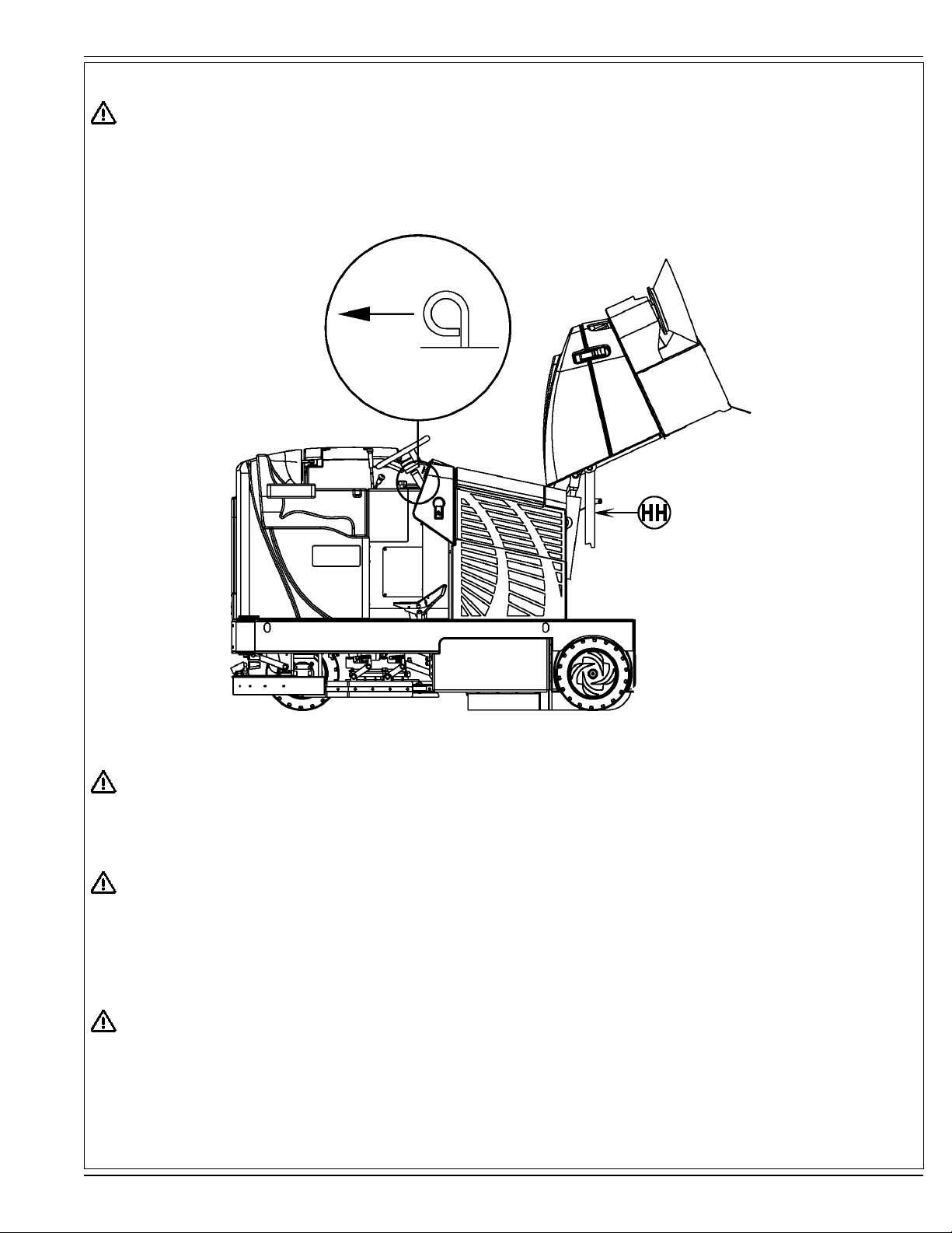
HOPPER SAFETY SUPPORT
WARNING!
Make sure the Hopper Safety Support (HH) is in place whenever attempting to do any maintenance work under or near the raised
hopper. The Hopper Safety Support (HH) holds the hopper in the raised position to allow work to be performed under the hopper.
NEVER rely on the machine’s hydraulic components to safely support the hopper.
JACKING THE MACHINE
CAUTION!
Never work under a machine without safety stands or blocks to support the machine.
• When jacking the machine, do so at designated locations (Do Not jack on the hopper) - see jacking locations (11)
TRANSPORTING THE MACHINE
CAUTION!
Before transporting the machine on an open truck or trailer, make sure that . . .
• All access doors are latched securely.
• The machine is tied down securely - see tie-down locations (4).
• The machine parking brake is set.
TOWING OR PUSHING A DISABLED MACHINE
CAUTION!
If the machine must be towed or pushed, make sure the Main Power Switch (CC) is in the OFF position and do not move the
machine faster than a normal walking pace (2-3 miles per hour) and for short distances only. If the machine is to be moved long
distances the rear drive wheel needs to be raised off the fl oor and placed on a suitable transport dolly.
FORM NO. 56041776 - CR 1100, CR 1200 - A-7
Page 8
A-8 / ENGLISH
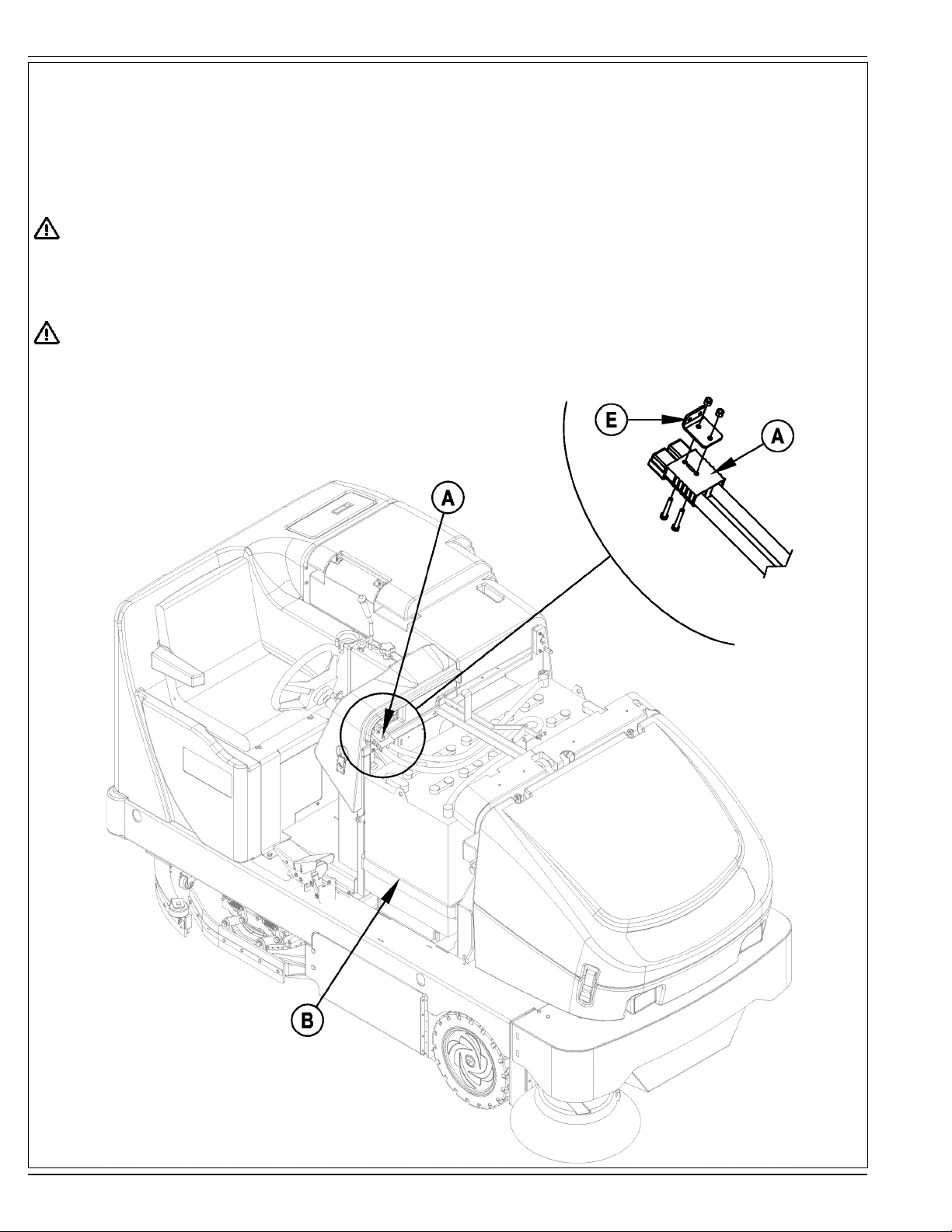
BATTERY INSTALLATION
See Figure 1 & 2. The battery required for this machine is sold separately. The maximum battery weight for this machine is 1,875 lbs (850 kg);
the minimum battery weight is 1,400 lbs (635kg). For proper battery installation, please consult your Nilfi sk Industrial Dealer. DO NOT attempt
to install the battery with an overhead hoist or forklift; it can only be installed with a battery cart. Connect the connector plug (A) on the battery to
the machine plug behind the steering wheel. Make sure the battery is fi rmly seated against the End Brace (B) on the driver’s side of the battery
compartment. Reinstall the battery Stop Plate (C) on the left side of the compartment and snug up the Bumpers (D) so the battery cannot slide
from side-to-side. NOTE: The Battery Disconnect Tab (E) has to be assembled to the Battery Connector Plug (A) on the battery.
WARNING!
Battery weight in excess of 1,875 lbs (850 kg) or below 1,400 lbs (635kg) may cause the premature failure of parts including the
tires, and may result in decreased stability and control, which could cause personal injury or death and/or property damage. Use of a
battery in excess of the weight limit will void the warranty.
IMPORTANT!
Follow instructions packed with the battery and charger before charging the battery. Read the instructions for Charging the Battery in
the Maintenance section of this manual.
FIGURE 1
A-8 - FORM NO. 56041776 - CR 1100, CR 1200
Page 9
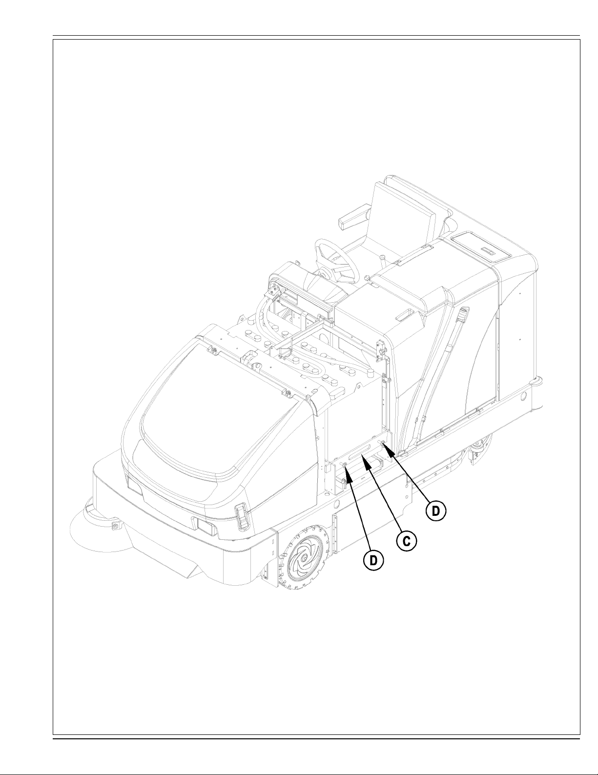
FIGURE 2
ENGLISH / A-9
FORM NO. 56041776 - CR 1100, CR 1200 - A-9
Page 10
A-10 / ENGLISH
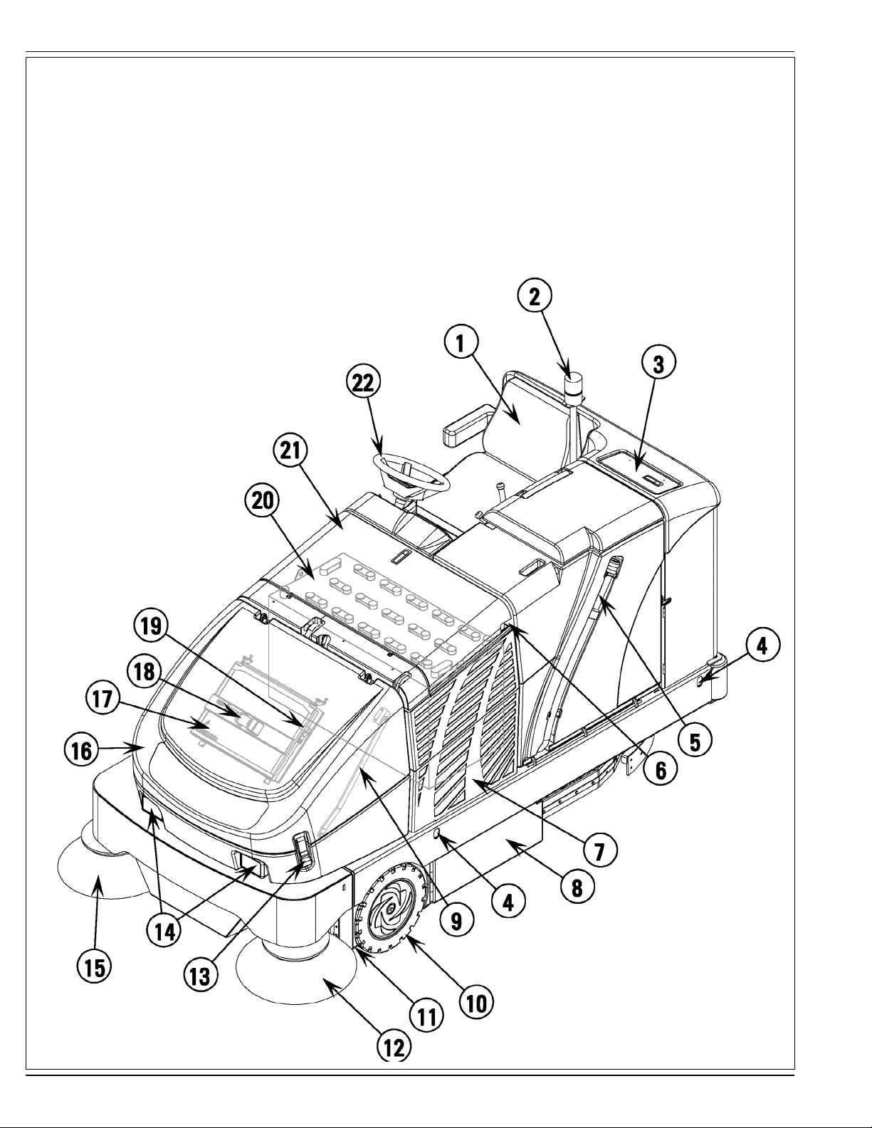
KNOW YOUR MACHINE
1 Operator’s Seat
2 Strobe Light (optional / standard on Nilfi sk Models)
3 Solution Tank Fill
4 Tie Down Locations
5 Recovery Tank Drain Hose
6 Recovery Tank Latch
7 Left Battery Compartment Access Panel
8 Main Broom Left Access Door
9 Hopper Cover Prop Rod
10 Front Wheel
11 Jacking Location
12 Left Side Broom
13 Hopper Cover Latch
14 Headlights
15 Right Side Broom
16 Hopper Cover
17 Dust Control Filter
18 Dust Control Shaker Assembly
19 Shaker Assembly Latch
20 Battery
21 Battery Compartment Door
22 Steering Wheel
A-10 - FORM NO. 56041776 - CR 1100, CR 1200
Page 11

KNOW YOUR MACHINE (CONTINUED)
23 Electrical Compartment Door
24 Water Level Gauge
25 Recovery Tank Lid
26 Recovery Tank “Tip-Out” Grip
27 Hydraulic Power Unit (Reservoir & Filter)
28 Right Battery Compartment Access Panel
29 Main Broom Right Access Door
30 Access Door Latch
31 Skirt Assembly
32 Inline Solution Filter
33 Solution Tank Drain Hose
34 Rear Roller Bumper
35 Squeegee Tool Handle
36 Squeegee Tool Assembly
37 Tail Light
ENGLISH / A-11
FORM NO. 56041776 - CR 1100, CR 1200 - A-11
Page 12

A-12 / ENGLISH
CONTROL PANEL
A Low Battery Indicator
B Horn
* Horn ON Indicator
C Parking Brake Indicator (not used)
D Headlights
* Headlight ON Indicator
E Machine Needs Service Indicator
F Hydraulic Filter Plugged Indicator
G Speed Switch
* Speed Switch Indicator
H Scrub Pressure Decrease Switch
* Scrub Pressure Decrease Indicator
I Scrub Pressure Increase Switch
* Scrub Pressure Increase Indicator
J Scrub Pressure Display
K Solution Switch
* Solution ON Indicator
L Solution Tank Empty Indicator
M Recovery Tank Full Indicator
N Vacuum System Switch
* Vacuum System ON Indicator
O Scrub System OFF Switch
* Scrub System Indicator
P Side Broom ON
* Side Broom ON Indicator
Q Main Broom ON Indicator
R Light Sensor
S Shaker Switch
* Shaker ON Indicator (left)
* Dust Filter Plugged Indicator (right / optional)
T Dust Control Switch
* Dust Control ON Indicator
U Side Broom UP/OFF Switch
* Side Broom OFF Indicator
V Open Dump Door Switch
* Open Dump Door Indicator
W Hopper Open Indicator
X Hopper Overtemp Indicator
Y Close Dump Door Switch
* Close Dump Door Indicator
Z Lower Hopper Switch
* Lower Hopper Indicator
AA Raise Hopper Switch
* Raise Hopper Indicator
BB Hour Meter Display
CC Main Power Switch
DD Battery Condition Indicator
A-12 - FORM NO. 56041776 - CR 1100, CR 1200
Page 13

OPERATOR’S COMPARTMENT
EE Solution Flow Control Lever
FF Main Broom Raise/Lower (ON/OFF) Lever
GG Main Broom Adjust Knob
HH Hopper Safety Support Lever
II Control Panel
JJ Main Broom Overload Indicator Light
KK Emergency Battery Disconnect
LL Tilt Wheel Lever
MM Drive Pedal
NN Brake Pedal
OO Parking Brake Latch
PP Operator Seat Adjustment Lever
ENGLISH / A-13
FORM NO. 56041776 - CR 1100, CR 1200 - A-13
Page 14

A-14 / ENGLISH
PRE-OPERATIONAL CHECKLIST
Before Each Use:
* Inspect the machine for damage or oil and water leaks.
* Check the hydraulic oil level (27).
* Make sure the recovery tank is empty.
* Make sure the battery charger is not connected to the machine.
* Check battery charge condition.
In the Driver’s Seat:
* Be sure that you understand the operating controls and their functions.
* Adjust the seat to allow easy reach of all controls.
* Insert the Master Key and turn the Ignition Key Switch (CC) to the ON position. Check for proper operation of the Horn (B), Hour Meter (BB)
and Headlights (14). Turn the Ignition Key Switch (CC) OFF.
* Check the Parking Brake Latch (OO). The latch must hold its (locked parked) setting fi rmly with out easily being released.
(Report all defects immediately to service personnel).
Plan Your Cleaning in Advance:
* Presweep heavily littered areas for more effi cient operation.
* Arrange long runs with a minimum of stopping or starting.
* Allow 6 inches of broom path overlap to ensure complete coverage.
* Avoid making sharp turns, bumping into posts, or scraping the side of the machine.
MAIN BROOM
Several different main brooms are available for this machine. Contact your Nilfi sk dealer if you need help selecting the best broom for the surface
and litter that you will be sweeping. NOTE: Reference broom maintenance for installation steps.
SCRUB BRUSH INSTALLATION
1 Make sure the Key Switch (CC) is off (O). See Figure 3. Remove side skirt assemblies for easier access. NOTE: Loosen large Black Knob
(A) at the front of each skirt mounting bracket, slide the skirt assembly forward and lift straight UP and off scrub deck.
2 To mount the brushes (or pad holders) align the lugs on the brush with the holes on the mounting plate and turn to lock in place according to
rotation directions shown in Figure 4.
A-14 - FORM NO. 56041776 - CR 1100, CR 1200
Page 15

FIGURE 3
ENGLISH / A-15
FIGURE 4
TOP VIEW OF SCRUB DECK SHOWING DIRECTION TO ROTATE
BRUSHES WHILE INSTALLING FOR EACH BRUSH MOTOR
Outside arrows represent brush installation rotation direction. Inside arrows represent brush
motor rotation while scrubbing.
FORM NO. 56041776 - CR 1100, CR 1200 - A-15
Page 16

A-16 / ENGLISH
FILLING THE SOLUTION TANK
The solution tank fi ll (3) is located at the left rear corner of the machine and has a 75 gallon (284 liter) maximum capacity. Fill the tank with the proper dilution of cleaning
chemical mixed with water according to the manufacturer’s recommendations. If using a powdered chemical, mix it with water in a bucket before putting it into the
machine’s solution tank. NOTE: DO NOT fi ll the tank past the Maximum Level on the Water Level Gauge (24). NOTE: EDS machines can either be used conventionally
with detergent mixed in the tank or the EDS detergent dispensing system can be used. When using the EDS detergent dispensing do not mix detergent in the tank, plain
water should be used.
CAUTION!
Use only low-sudsing, non-fl ammable, non-caustic cleaning chemicals intended for machine application.
DETERGENT SYSTEM PREPARATION AND USE (EDS MODELS ONLY)
Fill the detergent cartridge with a maximum of 2.2 gallons (8.32 Liters) of detergent. SERVICE NOTE: Remove the detergent cartridge from the detergent box prior to
fi lling to avoid spilling detergent on the machine.
It is recommended that a separate cartridge be used for each detergent you plan to use. The detergent cartridges have a white decal on them so you can write the detergent name
on each cartridge to avoid mixing them up. The detergent cartridge has a Magnetic Slider (A) on one end that needs to be set to the proper dilution ratio according to the dilution
instructions on the manufacturer’s bottle. Slide the Magnet Slider (A) to the appropriate location on Detergent Dilution Ratio Decal (B). When installing a new cartridge, remove the
Cap (C) and place the cartridge in the detergent box. Install the Dry Break Cap (D) as shown.
The system should be purged of previous detergent when switching to a different detergent. SERVICE NOTE: Move machine over fl oor drain before purging because a small amount
of detergent will be dispensed in the process.
To Purge When Changing Chemicals:
1 Disconnect and remove the detergent cartridge.
2 Turn the Key Switch (CC) ON and press the Detergent ON/OFF Switch (RR) for at least 2 seconds. NOTE: Once activated the purge process takes 10 seconds. See illustration
on next page for Detergent System indicators. Normally one purge cycle is adequate to purge the system.
To Purge Weekly:
1 Disconnect and remove the detergent cartridge. Install and connect a Cartridge fi lled with clean water
2 Turn the Key Switch (CC) ON and press the Detergent ON/OFF Switch (RR) for at least 2 seconds. NOTE: Once activated the purge process takes 10 seconds. See illustration
on next page for Detergent System indicators. Normally one purge cycle is adequate to purge the system.
The Detergent Box (E) has a Detergent Level Viewing Slot (F) for keeping track of how much detergent is remaining in the cartridge. When the detergent level is nearing the bottom
of this slot it is time to refi ll or replace the cartridge.
General Use:
The detergent (EDS) system is enabled when the Key Switch (CC) is turned on and reverts to the last state (Chem On or Chem Off) it was in prior to the last power down. The current
Solution Flow Rate (VV) and the last used Detergent Ratio (WW) (if in “Chem On” state) are displayed. The Status LED (YY) indicates the status of the system as follows:
GREEN: Solution not low and chemical pump ON (pumping solution and chemical)
BLINKING GREEN: Purge has been activated
LED OFF: Solution fl ow position = 0 or solution solenoid is OFF
ORANGE: Solution ON and Chemical OFF (pumping solution only)
BLINKING RED: Solution low and chemical pump ON (pumping
solution only)
No detergent is dispensed until the scrub system is activated and
the Drive Pedal (MM) pushed forward. The detergent ratio can be
varied by subsequently pressing the Detergent Ratio Increment and
Decrement Switches (SS & TT). The detergent fl ow rate increases or
decreases with the solution fl ow rate but the detergent ratio remains
the same unless changed. During scrubbing, the detergent system
can be turned off at any time by pressing the Detergent ON/OFF
Switch (RR) to allow scrubbing with water only. On EDS models
the solution fl ow rate (40%-100%) is electronically controlled and is
displayed (VV) on the EDS display panel as shown below.
SERVICE NOTE: Follow the “To Purge Weekly” instructions above
if the machine is going to be stored for an extended period of time
or if you plan to discontinue use of the detergent (EDS) system.
The Display Panel (UU) will display an Error Code “E1” (XX) in the
lower left corner if the magnetic slider circuit board (ZZ) becomes
disconnected or malfunctions.
A-16 - FORM NO. 56041776 - CR 1100, CR 1200
Page 17

DETERGENT SYSTEM PREPARATION AND USE (EDS MODELS ONLY)
ENGLISH / A-17
FORM NO. 56041776 - CR 1100, CR 1200 - A-17
Page 18

A-18 / ENGLISH
OPERATING THE MACHINE
This is a rider-type automatic fl oor sweeping and scrubbing machine. It is designed to sweep up debris, lay down cleaning solution, scrub the
fl oor, and vacuum dry all in one pass. The sweeping and scrubbing operations can also be performed separately.
The controls were designed with one touch operation in mind. For single pass scrubbing the user can simply depress one switch and all scrub
functions on the machine will be ready to go. For sweeping, the operator can simply lower the main broom and all sweeping functions will be ready
to go.
Use the Drive Pedal (MM) to control the speed of the machine. The speed of the machine will increase as the pedal is pushed closer to the fl oor.
Do not press the Drive Pedal (MM) until the Main Power Switch (CC) has been turned on.
SWEEPING
Follow the instructions in preparing the machine for use section of this manual.
1 While seated on the machine, adjust the seat and steering wheel to a comfortable operating position using the adjustment controls (PP) and
(LL).
2 Release the Parking Brake (OO). To transport the machine to the work area, apply even pressure with your foot on the front of the Drive
Pedal (MM) to go forward or the rear of the pedal for reverse. Vary the pressure on the foot pedal to obtain the desired speed.
3 Push the Lower Hopper Switch (Z) to make sure the hopper is seated properly.
4 Move the Main Broom Lever (FF) to the SWEEP (middle notch) position to lower and enable the main broom. NOTE: The dump door opens
automatically when the main broom (FF) is lowered and closes when the broom is raised.
Use the FULL FLOAT (last notch forward) position only when sweeping extremely rough or uneven fl oors. Use at other times will only
increase broom wear.
5 When sweeping dry fl oors, push the Dust Control Switch (T) to turn ON the dust control system.
When sweeping fl oors with puddles, push the Dust Control Switch (T) to turn OFF the dust control system before the machine enters a
puddle. Turn the dust control system back ON when the machine is back on completely dry fl oor.
When sweeping wet fl oors, keep the Dust Control Switch (T) OFF at all times.
6 Lower the Side Broom(s) (P) when sweeping along walls or curbs. Raise the Side Broom(s) (U) when sweeping in open areas. Push and
hold the Side Broom ON/DOWN Switch (P) to lower and start the side broom motor(s). NOTE: Hold the switch until the side broom(s)
have lowered to the desired level. Side broom sweeping pattern is adjusted by pushing switches (P & U) until the desired amount of down
pressure is achieved. NOTE: If the side broom(s) were not raised and turned OFF after last use, they will automatically lower and turn ON
when the main broom is lowered and starts.
7 Drive the machine straight forward at a quick walking speed. Drive the machine slower when sweeping large amounts of dust or debris or
when safe operation dictates slower speeds. Overlap passes 6 inches (15 cm).
8 If dust comes out of the broom housing while sweeping, the Dust Control Filter (17) may be clogged. Push the Shaker Switch (S) to clean the
dust control fi lter. The dust control system (T) will automatically turn OFF while the shaker is running and turn ON after the shaker turns OFF
(the shaker runs for 20 seconds).
9 Check behind the machine occasionally to make sure that the machine is picking up debris. Dirt left behind in the path of the machine usually
indicates that the machine is moving too fast, the broom needs to be adjusted, or the hopper is full.
EMPTYING THE HOPPER
WARNING!
Make sure the Hopper Safety Support (HH) is in place whenever attempting to do any maintenance work under or near the raised
hopper. The Hopper Safety Support (HH) holds the hopper in the raised position to allow work to be performed under the hopper.
NEVER rely on the machine’s hydraulic components to safely support the hopper.
1 Push the Shaker Switch (S) to remove excess dirt from the dust control fi lter. SERVICE NOTE: For best shaker performance always run
the shaker with the hopper fully down.
2 Drive the machine close to a large trash receptacle and hold the Raise Hopper Switch (AA) until the hopper is all the way up. NOTE: The
dump door automatically closes when switch (AA) is pushed. You regain control of the dump door as soon as the hopper begins to raise so
you can dump at any height if necessary.
3 Move the machine forward until the hopper is over the receptacle, then press the Open Dump Door Switch (V) to open the dump door and
empty the hopper.
4 Check the back of the hopper and the front of the broom housing. Use a broom, if necessary, to remove litter from these areas. The back of
the hopper must seal tightly against the front of the broom housing for proper operation.
5 Back the machine away from the receptacle until the hopper will clear it, and then lower the hopper (Z). NOTE: The dump door will
automatically open when sweep function is resumed.
A-18 - FORM NO. 56041776 - CR 1100, CR 1200
Page 19

ENGLISH / A-19
SCRUBBING
Follow the instructions in preparing the machine for use section of this manual.
1 While seated on the machine, adjust the seat and steering wheel to a comfortable operating position using the adjustment controls (PP) and (LL).
2 Release the Parking Brake (OO). To transport the machine to the work area, apply even pressure with your foot on the front of the Drive Pedal (MM) to go
forward or the rear of the pedal for reverse. Vary the pressure on the foot pedal to obtain the desired speed.
3 Adjust the Solution Flow Control Lever (EE) to about 1/4 to 1/3 (40%-100% on EDS) open position. The adjustment can be changed to allow variable
solution fl ow for different types of fl oors to be scrubbed. Example: A rough or absorbent fl oor surface, such as unfi nished concrete will require more solution
than a smooth fi nished fl oor.
4 Press the Solution Switch (K) and hold for 5 seconds. This is done to pre-wet the fl oor. Note: This will help prevent scarring of the fl oor surface when
starting to scrub with dry brushes.
5 Press the Scrub Pressure Decrease Switch (H) or the Scrub Pressure Increase Switch (I) to activate the scrub system.
6 When the Scrub Pressure Decrease Switch (H) or the Scrub Pressure Increase Switch (I) are selected, the brushes and squeegee are automatically lowered
to the fl oor. The machine’s scrub brush rotation, solution system fl ow, detergent fl ow(EDS only) and vacuum starts when the Drive Pedal (MM) is activated.
Note: When operating the machine in reverse, only the brushes will rotate, the solution and detergent(EDS only) is automatically shut off and the squeegee
raises.
7 Begin scrubbing by driving the machine forward in a straight line at a normal walking speed and overlap each path by 6 inches (15 cm). Adjust the machine
speed and solution fl ow according to the condition of the fl oor.
CAUTION!
To avoid damaging the fl oor, keep the machine moving while the brushes are turning.
8 When scrubbing, check behind the machine occasionally to see that all of the waste water is being picked up. If there is water trailing the machine, you may
be dispensing too much solution, the recovery tank may be full, or the squeegee tool may require adjustment.
9 For extremely dirty fl oors, a one-pass scrubbing operation may not be satisfactory and a “double-scrub” operation may be required. This operation is the
same as a one-pass scrubbing except on the fi rst pass the squeegee is in the up position (press the Vacuum Switch (N) to raise the squeegee). This
allows the cleaning solution to remain on the fl oor to work longer. The fi nal pass is made over the same area, with the squeegee lowered to pick up the
accumulated solution.
10 The recovery tank has an automatic vacuum shut-off to prevent solution from entering the vacuum system when the recovery tank is full. When the vacuum
shut-off is activated, the control system will shut down the vacuum system. The Recovery Tank FULL Indicator (M) will light. When the vacuum shut-off is
activated, the recovery tank must be emptied.
11 When the operator wants to stop scrubbing or the recovery tank is full, press the Scrub System OFF Switch (O) once. This will automatically stop the scrub
brushes, solution fl ow, detergent fl ow(EDS only) and the scrub deck will raise UP. NOTE: the vacuum/squeegee system will not be turned off when the
switch is only pressed once. This is to allow any remaining water to be picked up without turning the vacuum back on. Press the switch a second time and
the squeegee will raise and the vacuum will stop after a 10 second delay.
12 See the instructions below for emptying the recovery tank. Refi ll the solution tank and continue scrubbing.
EMPTYING THE RECOVERY TANK
1 Drive the machine to a designated waste water “DISPOSAL SITE”.
2 To empty, pull the Drain Hose (5) from its storage area, hold the end of the hose above the water level in the tank to avoid sudden, uncontrolled fl ow of waste
water and open the cap. NOTE: You can also pinch the fl exible end of the hose to control waste water fl ow as shown below.
3 Flush the tank and drain hose with clean water.
4 Reclose the cap and return the hose to its storage area.
SERVICE NOTE: The recovery tank can be tipped out to the side for cleaning after emptying. Release the Latch (6) at the front of the tank and then pull out on
the tank with grip (26) until the tank reaches the end of its tether. Remove the recovery tank lid for easier cleaning. The recovery tank can also be removed for
cleaning. You will need to disconnect the wire harness and tether fi rst and then use at least 2 people to lift off.
SERVICE NOTE: Refer to the service manual for detailed functional descriptions of all controls and optional programmability.
FORM NO. 56041776 - CR 1100, CR 1200 - A-19
Page 20

A-20 / ENGLISH
AFTER USE
1 Raise the squeegee, the scrub brushes, and the brooms.
2 Shake the dust control fi lter and empty the hopper.
3 Drain and fl ush the recovery tank.
4 Tip the recovery tank out and check the squeegee hose elbow below the tank for debris. DO NOT run water down the recovery tank vacuum
tubes, this may cause damage to the vacuum motors.
5 Remove and clean the squeegee tool.
6 Remove and clean the scrub brushes. Rotate the scrub brushes.
7 Wipe the machine with a damp cloth.
8 Perform all required maintenance before storage.
9 Move the machine to a clean, dry storage area.
10 Store the machine with the brooms, the squeegee and the scrub brushes in the UP position, and the tank covers open so that the tanks can
air out.
REPORT ANY DEFECT OR MALFUNCTION NOTED DURING OPERATION TO AUTHORIZED SERVICE OR MAINTENANCE PERSONNEL.
MAINTENANCE SCHEDULE
Keep the machine in top condition by following the maintenance schedule closely. Maintenance intervals given are for average operating
conditions. Machines used in severe environments may require service more often.
25 150 300 Yearly
MAINTENANCE ITEM Daily Hours Hours Hours (1,000hrs)
Charge Battery X
Drain / Check / Clean Tanks & Hoses X
Check / Clean / Rotate Scrub Brushes & Pads X
Check / Clean / Adjust Squeegee X
*Check / Clean Vacuum Motor Inlet Screen Cap X
Clean Solution Filter (32) X
Check Battery Cell Water Level(s) X
Check Foot/ Parking Brake For Wear & Adjustment X
Inspect Broom Housing Skirts X
Check Hydraulic Fluid Level X
Check / Clean Hopper Dust Control Filter Using Method “A” X
Inspect Scrub Deck Skirts X
Main Broom Maintenance X
Side Broom Maintenance X
Purge Detergent System (EDS only) X
** Lubrication X
Inspect Main Broom Upper & Lower Belts X
Check / Clean Hopper Dust Control Filter Using Method “B” X
Check / Clean Hopper Dust Control Filter Using Method “C” X
Replace Hydraulic Oil & Filter X
*** Check Carbon Brushes X
Have Nilfi sk service center inspect the wheel drive gearbox X
* DO NOT run water down the vacuum tube in the recovery tank this will damage the vacuum motors. Vacuum tube is on left side of tank with
screen cap.
** If the machine is being used in a very dusty or wet environment the lubrication should be performed once per week.
*** Have your Nilfi sk Dealer check the carbon motor brushes once a year or after 300 operating hours.
NOTE: Refer to the Service Manual for more detail on maintenance and service repairs.
A-20 - FORM NO. 56041776 - CR 1100, CR 1200
Page 21

ENGLISH / A-21
CHARGING THE BATTERY
Charge the battery each time the machine is used, or whenever the Battery Condition Meter Lights (DD) are fl ashing.
To Charge the Battery...
1 Open the Battery Compartment Door (21) to provide proper ventilation.
2 Disconnect the battery from the machine (KK) and connect the charger plug to the battery plug.
3 Follow the instructions on the battery charger.
4 Check the fl uid level in all battery cells after charging the battery. Add distilled water, if necessary, to bring the fl uid level up to the bottom of
the fi ller tubes.
WARNING!
Do not fi ll the battery before charging.
Only charge battery in a well-ventilated area.
Do not smoke while servicing the battery.
CAUTION!
To avoid damage to fl oor surfaces, always wipe water and acid from the top of the battery after charging.
CHECKING THE BATTERY ELECTROLYTE LEVEL
Check the electrolyte level of the battery at least once a week.
After charging the battery, remove the vent caps and check the electrolyte level in each battery cell. Use distilled water to fi ll the battery to the
bottom of the fi ller tube.
Do not over-fi ll the battery!
CAUTION!
Acid can spill onto the fl oor if the battery are overfi lled.
Tighten the vent caps. If there is acid on the battery, wash the tops of the battery with a solution of baking soda and water (2
tablespoons of baking soda to 1 quart of water).
FORM NO. 56041776 - CR 1100, CR 1200 - A-21
Page 22

A-22 / ENGLISH
MAIN BROOM MAINTENANCE
Since the Main Broom Motor always turns in the same direction, the bristles on the broom eventually become curved, reducing sweeping
performance. Sweeping performance can be improved by removing the broom and turning it around (end-for-end). This procedure, known as
“rotating” the main broom, should be done once every 25 hours of operation.
The main broom should be replaced when the bristles are worn to a length of 2-1/2 inches (6.35 cm). The main broom stop (GG) must be readjusted when the broom is replaced. NOTE: Bristle length on a new broom is 3-1/4 inches (8.25cm).
NOTE: The machine should be stored with the Main Broom in the raised position.
WARNING!
Disconnect the battery (KK) before performing this operation.
To Rotate or Replace the Main Broom...
1 Turn the Main Power Switch (CC) OFF.
2 Put the Main Broom Raise / Lower (ON / OFF) Lever (FF) in the DOWN position.
3 Open the Main Broom Right Access Door (29).
4 See Figure 5. Remove the large T-Bolt (A) from the side of the broom idler arm. Pivot the idler arm assembly out of the main broom core.
5 Pull the main broom out of the broom housing and remove any string or wire wrapped around it. Also inspect the skirts at the front, back and
sides of the broom housing. The skirts should be replaced or adjusted if they are torn or worn to a height of more than 1/4 inch (6.35 mm) off
the ground.
6 Turn the broom around (end-for-end) and slide it back into the broom housing. Make sure that the Lugs (B) on the broom drive hub (left side
of machine) engage the slots in the broom core.
7 Swing the idler arm assembly back into the broom core and re-install the T-Bolt that holds the idler arm in place.
8 Close and latch the Main Broom Right Access Door (29).
To Adjust the Main Broom Height...
1 Drive the machine to an area with a level fl oor and set the parking brake (OO).
2 Pull the Main Broom Raise / Lower (ON/OFF) Lever (FF) back and slide to the right and up to lower the main broom. Push lightly on the front
of the Drive Pedal (MM) to start the main broom rotating. DO NOT move the machine.
3 Let the main broom run in place for 1 minute. This allows the broom to polish a “strip” on the fl oor. After 1 minute, raise the broom, release
the parking brake and move the machine so that the polished strip is visible.
4 Inspect the polished strip on the fl oor. If the strip is less than 2 inches (5.08 cm) or more than 3 inches (7.62cm) wide, the broom needs to be
adjusted.
5 To adjust, loosen the Main Broom Adjust Knob (GG) and slide forward or backward to lower or raise the Main Broom. The farther the Knob
(GG) travels up in the slot, the lower the Main Broom will be. Tighten Knob (GG) after adjustment is complete.
6 Repeat steps 1-5 until the polished strip is 2-3 inches (5.08-7.62cm) wide.
The width of the polished strip should be the same at both ends of the broom. If the strip is tapered, move the machine to a different area and
repeat steps 1-5. If the polished strip is still tapered, contact your Nilfi sk Dealer for service.
FIGURE 5
A-22 - FORM NO. 56041776 - CR 1100, CR 1200
Page 23

ENGLISH / A-23
SIDE BROOM MAINTENANCE
The side broom(s) move dirt and debris away from walls or curbs and into the path of the main broom. Adjust the side broom so that the bristles
are contacting the fl oor from the 10 O’clock (A) to the 3 O’clock (B) area shown in Figure 6 when the broom is down and running.
To adjust the Side Broom...
1 The side broom(s) are adjusted simply by pressing and holding the Side Broom DOWN/ON Switch (P) or the Side Broom UP/OFF Switch (U)
until the desired amount of bristles are contacting the fl oor.
NOTE: The machine should be stored with the Side Broom(s) in the raised position. The Side Broom(s) should be replaced when the bristles are
worn to a length of 3 inches (7.62 cm) or they become ineffective.
To replace the Side Broom...
1 Raise the Side Broom(s).
2 Reach under the Side Broom and remove the large Thumb-Nut holding the side broom on and remove the broom.
3 Install the new broom by aligning the three alignment pins and pushing on. Re-install the Thumb-Nut and tighten.
FIGURE 6
FORM NO. 56041776 - CR 1100, CR 1200 - A-23
Page 24

A-24 / ENGLISH
SQUEEGEE MAINTENANCE
After each use, clean the squeegee tool and check the blades for damage. If the squeegee leaves water in the middle of its path or at both ends
of its path, it probably needs to be adjusted. Reverse or replace the blades if they are cut, torn, wavy or worn.
To adjust the squeegee:
1 Park the machine on a level fl oor, lower the squeegee and drive forward a short distance.
2 See Figure 7. Loosen the two Squeegee Adjustment Lock Nuts (A).
3 Turn the two Squeegee Adjustment Bolts (B) counter-clockwise for forward tilt or clockwise for backward tilt. Pull forward a short distance
after each adjustment to see if the squeegee blades touch the fl oor evenly across the entire width of the squeegee tool. Then re-tighten the
two Nuts (A). NOTE: Hold Bolts (B) with wrench while tightening Lock Nuts (A). If adjusting for more forwards tilt, tightening the Locknuts
(A) after loosening the Adjustment Bolts (B) is what will actually tilt the squeegee assembly.
To reverse or replace the rear squeegee blade:
1 Unlatch the Rear Squeegee Blade Latch (C) and remove the (2) Wing Nuts (D).
2 Remove both Rear Straps (E) and the Rear Squeegee Blade (F) from the machine.
3 The squeegee blade has 4 working edges. Turn the blade so a clean, undamaged edge points toward the front of the machine. Replace the
blade if all 4 edges are nicked, torn or worn to a large radius.
4 Install the blade, following the steps in reverse order and adjust the squeegee tilt.
To reverse or replace the front squeegee blade:
1 Disconnect the Squeegee Hose from the squeegee tool.
2 Loosen the (2) Squeegee Levers (G) and slide the squeegee assembly off of the squeegee mount.
SERVICE NOTE: Depending on the position of the Squeegee Lever Handle (H), you may not be able to rotate the lever far enough to loosen
or tighten depending on which you are trying to do. In this case, simply lift UP on the Handle (H) and rotate the lever in the direction necessary
to acquire adequate turning space and then allow the lever to drop back DOWN into place on the hex. You can then either tighten or loosen as
needed.
3 Remove all of the Wing Nuts from the front squeegee blade strap.
4 Remove the strap and blade from the squeegee assembly.
5 The squeegee blade has 4 working edges. Turn the blade so a clean, undamaged edge points toward the front of the machine. Replace the
blade if all 4 edges are nicked, torn or worn to a large radius.
6 Install the blade, following the steps in reverse order and adjust the squeegee tilt.
FIGURE 7
A-24 - FORM NO. 56041776 - CR 1100, CR 1200
Page 25

ENGLISH / A-25
HOPPER DUST CONTROL FILTER
The hopper dust control fi lter must be cleaned regularly to maintain the effi ciency of the vacuum system. Follow the recommended fi lter service
intervals for the longest fi lter life.
CAUTION!
Wear safety glasses when cleaning the fi lter.
Do not puncture the paper fi lter.
Clean the fi lter in a well-ventilated area.
To remove the hopper dust control fi lter...
1 Lift the Hopper Cover (16) on top of the hopper. Make sure that the Hopper Cover Prop Rod (9) is in place.
2 Inspect the top of the Hopper Dust Control Filter (17) for damage. A large amount of dust on top of the fi lter is usually caused by a hole in the
fi lter or a damaged fi lter gasket.
3 Turn the two hold-downs to the side (one on each side at the front of the frame) to release the shaker frame, then swing the Dust Filter
Shaker Assembly (18) up and latch in place with the Shaker Assembly Latch (19).
4 Lift the Hopper Dust Control Filter (17) out of the machine.
5 Clean the fi lter using one of the methods below:
Method “A”
Vacuum loose dust from the fi lter. Then gently tap the fi lter against a fl at surface (with the dirty side down) to remove loose dust and dirt.
NOTE: Take care not to damage the metal lip which extends past the gasket.
Method “B”
Vacuum loose dust from the fi lter. Then blow compressed air (maximum pressure 100 psi) into the clean side of the fi lter (in the opposite
direction of the airfl ow).
Method “C”
Vacuum loose dust from the fi lter. Then soak the fi lter in warm water for 15 minutes, and then rinse it under a gentle stream of water
(maximum pressure 40 psi). Let the fi lter dry completely before putting it back into the machine.
6 Follow the instructions in reverse order to install the fi lter. If the gasket on the fi lter is torn or missing, it must be replaced.
HYDRAULIC OIL
Raise and prop (HH) the hopper. See Figure 8. The oil level should be approximately 1 inch (2.54cm) below the bottom of the Elbow (A) on the
front of the reservoir when the hopper is up (when the hopper is fully down the oil level should be up to the bottom of the elbow). If it is below this
level, add 10W30 motor oil. Change the oil if major contamination from a mechanical failure occurs. SERVICE NOTE: The Plug (B) on Elbow (A)
on the side of the reservoir is for adding oil. Service Note: Remove Vent Plug (D) to allow faster fi lling.
IMPORTANT!
This machine is equipped with an Indicator Light (F) which lights if the Hydraulic Oil Filter (C / Figure 8) requires changing. The
Hydraulic Filter (C / Figure 8) is found on the side of the Hydraulic Power Unit (27) as shown.
FIGURE 8
FORM NO. 56041776 - CR 1100, CR 1200 - A-25
Page 26

A-26 / ENGLISH
DRIVE WHEEL GEAR CASE OIL
Change the gear lube in the drive wheel gear case after the fi rst 350 hours of operation (break in period).
Required oil specifi cation: API GL4, SAE 80/90 weight gear oil.
Gear case oil fi ll capacity is 2.8 quarts (2.7 liters). NOTE: Refer to service manual for drain and fi ll instructions.
LUBRICATION
Grease Fitting locations:
* 1 on each steering sprocket, 6 total.
* 1 on each squeegee caster, 2 total
* 2 on drive wheel gear case spindle (A)
Turn the transmission from side-to-side slowly
while greasing to distribute grease evenly.
Lube Oil locations:
* steering chain.
CIRCUIT BREAKER LOCATION
A Circuit Breaker, 25A (Auxiliary Circuit 1 / F1)
B Circuit Breaker, 5A (Auxiliary Circuit 2 / F2)
C Circuit Breaker, 20A (Auxiliary Circuit 3 / F3)
D Circuit Breaker, 15A (Dust Control Motor / F4)
E Circuit Breaker, 20A (Side Broom Motors / F5)
F Circuit Breaker, 70A (Hydraulic Pump / F7)
G Circuit Breaker, 40A (Vacuum Motors / F8)
H Circuit Breaker, 40A (Power Steering / F9)
I Circuit Breaker, 10A (EDS / F6)
FIGURE 9
A-26 - FORM NO. 56041776 - CR 1100, CR 1200
Page 27

ENGLISH / A-27
TROUBLESHOOTING
If the possible causes listed below are not the source of trouble, it is a symptom of something more serious. Contact your Nilfi sk Service Center
immediately for service.
TRIPPING THE CIRCUIT BREAKERS
The circuit breakers are located on the Circuit Breaker Panel in the operator’s compartment; they protect electrical circuits and motors from
damage due to overload conditions. If a circuit breaker trips, try to determine the cause.
Auxiliary Circuit 1 Circuit Breaker (25 Amp) Possible cause may be:
1 Electrical short circuit (have your Nilfi sk Service Center or qualifi ed electrician check the machine)
Auxiliary Circuit 2 Circuit Breaker (5 Amp) Possible cause may be:
1 Electrical short circuit (have your Nilfi sk Service Center or qualifi ed electrician check the machine)
Auxiliary Circuit 3 Circuit Breaker (20 Amp) Possible cause may be:
1 Electrical short circuit (have your Nilfi sk Service Center or qualifi ed electrician check the machine)
Dust Control Motor Circuit Breaker (15 Amp) Possible cause may be:
1 Electrical short circuit (have your Nilfi sk Service Center or qualifi ed electrician check the machine)
2 Overloaded or jammed shaker motor (check shaker motor)
Side Broom Motors Circuit Breaker (20 Amp) Possible cause may be:
1 Debris wrapped around the broom drive (remove debris)
2 Side broom set too low (adjust side broom)
3 Electrical short circuit (have your Nilfi sk Service Center or qualifi ed electrician check the machine)
Hydraulic Pump Circuit Breaker (70 Amp) Possible cause may be:
1 Overloaded or jammed hopper (check hopper)
2 Electrical short circuit (have your Nilfi sk Service Center or qualifi ed electrician check the machine)
Vacuum Motors Circuit Breaker (40 Amp) Possible cause may be:
1 Electrical short circuit (have your Nilfi sk Service Center or qualifi ed electrician check the machine)
Power Steering Circuit Breaker (40 Amp) Possible causes may be:
1 Electrical short circuit (have your Nilfi sk Service Center or qualifi ed electrician check the machine)
2 Overloaded or jammed power steering unit (check power steering unit)
EDS Circuit Breaker (10 Amp) Possible causes may be:
1 Electrical short circuit (have your Nilfi sk Service Center or qualifi ed electrician check the machine)
Once the problem has been corrected, push the button in to reset the circuit breaker. If the button does not stay in, wait 5 minutes and try again. If
the circuit breaker trips repeatedly, call your Nilfi sk Service Center for service.
FORM NO. 56041776 - CR 1100, CR 1200 - A-27
Page 28

A-28 / ENGLISH
TROUBLESHOOTING
If the possible causes listed below are not the source of trouble, it is
a symptom of something more serious. Contact your Nilfi sk Service
Center immediately for service.
MACHINE WILL NOT MOVE
Possible causes may be:
1 Parking Brake (OO) set (release parking brake)
2 Tripped circuit breaker(s) (reset any tripped circuit breakers)
3 Battery stop plate not installed (install battery stop plate)
4 Defective seat switch (replace seat switch)
MAIN BROOM WILL NOT RUN
Possible causes may be:
1 Debris wrapped around the broom drive (remove debris)
2 Hopper is not completely down (lower hopper completely)
3 Tripped circuit breaker(s) (reset any tripped circuit breakers)
SIDE BROOMS WILL NOT RUN
Possible causes may be:
1 Debris wrapped around the broom drive (remove debris)
2 Hopper is not completely down (lower hopper completely)
3 Tripped circuit breaker(s) (reset any tripped circuit breakers)
HOPPER WILL NOT RAISE
Possible causes may be:
1 Tripped circuit breaker(s) (reset any tripped circuit breakers)
POOR WATER PICKUP
Possible causes may be:
1 Worn or torn squeegee blades (reverse or replace)
2 Squeegee out of adjustment (adjust so blades touch the fl oor
evenly across entire width)
3 Recovery Tank Full (empty recovery tank)
4 Open recovery tank drain hose (secure drain hose cap or replace)
5 Recovery tank cover gasket leak (replace gasket)
6 Debris caught in squeegee (clean squeegee)
7 Vacuum hose clogged (remove debris)
8 Using too much solution (adjust solution control valve)
POOR SWEEPING PERFORMANCE
Possible causes may be:
1 Broom out of adjustment (adjust broom)
2 Hopper full (empty hopper)
3 Broom bristles worn or curved (replace or rotate broom)
4 Broom housing skirts damaged or worn (replace skirts)
POOR SCRUBBING PERFORMANCE
Possible causes may be:
1 Brush bristles worn or curved (rotate or replace brushes)
2 Wrong brush for job (consult Nilfi sk dealer)
3 Wrong cleaning chemical for job (consult Nilfi sk dealer)
4 Moving machine too fast (slow down)
5 Not using enough solution (adjust solution control valve)
HOPPER DUMP DOOR WILL NOT OPEN
Possible causes may be:
1 Dump door jammed by debris (remove debris and clean edges of
dirt chamber)
2 Tripped circuit breaker(s) (reset any tripped circuit breakers)
SHAKER MOTOR WILL NOT RUN
Possible causes may be:
1 Tripped circuit breaker(s) (reset any tripped circuit breakers)
VACUUM MOTORS DO NOT RUN
Possible causes may be:
1 Tripped circuit breaker(s) (reset any tripped circuit breakers)
2 Recovery tank full (empty recovery tank)
SCRUB SYSTEM WILL NOT RUN
Possible causes may be:
1 Tripped circuit breaker(s) (reset any tripped circuit breakers)
2 Hopper is not completely down (lower hopper completely)
INADEQUATE SOLUTION FLOW
Possible causes may be:
1 Not using enough solution (adjust solution control valve)
2 Solution tank empty (fi ll solution tank)
3 Solution lines or valves clogged (fl ush lines and valves)
4 Solution control valve not open (adjust solution control valve)
5 Solution switch OFF (turn ON solution switch)
NO DETERGENT FLOW (EDS)
Possible causes may be:
1 Tripped circuit breaker(s) (reset any tripped circuit breakers)
2 Empty detergent cartidge (fi ll detergent cartidge)
3 Plugged or kinked detergent fl ow line (Purge system, straighten
lines to remove any kinks)
4 Dry seal cap on detergent cartidge not sealed (reseat dry seal cap)
5 Detergent ratio slider magnet missing (replace slider)
6 Detergent pump wiring disconnected or backwards (connect or
reconnect wiring)
A-28 - FORM NO. 56041776 - CR 1100, CR 1200
Page 29

TECHNICAL SPECIFICATIONS (as installed and tested on the unit)
Model CR 1100 Battery CR 1200 Battery
Model No. 56303005 56303004
Voltage, Battery V 36 36
Battery Capacity AH 770 770
Protection Grade IPX3 IPX3
Sound Pressure Level
(IEC 60335-2-72: 2002 Amend. 1:2005, ISO 11201) dB (A)/20μPa 77.2 77.2
Total Weight lbs/kg 5,702 / 2,586 5,702 / 2,586
Maximum Wheel Floor Loading (right front) N/cm
Maximum Wheel Floor Loading (left front) N/cm
Maximum Wheel Floor Loading (center rear) N/cm
Vibrations at the Hand Controls (ISO 5349-1) m/s
Vibrations at the Seat (EN 1032) m/s
Gradeability
Transport 14.1% (8°) 14.1% (8°)
Cleaning 10.5% (6°) 10.5% (6°)
2
2
2
2
2
72
72
78
0.32 m/s
0.2 m/s
2
2
72
72
78
0.32 m/s
0.2 m/s
2
2
ENGLISH / A-29
FORM NO. 56041776 - CR 1100, CR 1200 - A-29
Page 30

Page 31

Overenstemmelseserklaering Declaration de conformit é Samsvarserklaering
Declaration of conformi ty Verklaring van overeenstemm i ng Vaatimustenmukaisuusvakuutus
Konformitätserklärung Dichiarazione di conformità Atitikties deklaracija
Declaración de conformidad Vastavussertifikaat Osvědčení o shodě
Atbilstības deklarācija Deklaracja zgodności Certifikát súladu
Megfelelősségi nyilatkozat Försäkran om överensstämmelse
Certifikat o ustreznost i
Modell/ Modèle/ Model/ Malli/ Modelo/ Μοντέλο/ Modelo/ Modelis/Модель: Scrubber
Typ e/ Tyyppi/ Tipo/ Τύπος/ Tüüp/ Tipas/ Tips/ Typ/ Típus/ Тип/ Tip: CR1200B
D Der Unterzeichner best ät i gt hiermit dass die oben erwähnten Modelle gemäß den folgenden Richtlinien und Normen hergestell t
wurden.
GB The undersigned certify that t he above mentioned model is produced in acc ordance with the following directives and standards.
DK Undertegnede att es terer herved, at ovennævnte model er produceret i overensstemmelse med fø l gende di rektiver og standarder.
N Undertegnede attes t erer at t ovennevnte modell är produsert I overensstemmelse med fölgende di rek tiv og standarder.
E El abajo firmante cert i fica que los modelos arriba m encionados han sido producidos de acuerdo con las siguientes directivas y
estandares.
I Il sottoscrit t o di chiara che i modelli sopra menzi onati sono prodotti in accordo con le s eguent i di rettive e standard.
EST Allakirjutanu kinnitab, et ülalnimetatud mudel on valmistatud koosk õl as järgmiste direktiivide j a normidega.
LV Ar šo tiek apliecināts, ka augstākminētais modelis ir izgatavots atbilstoši šādām direktīvām un standartiem.
CZ Níže podepsaný stvrzuje, že výše uvedený model byl vyroben v souladu s následujícími směrnicemi a normami.
SLO Spodaj podpisani potrjujem, da je zgoraj omenjeni model izdelan v skl adu z nas l ednj i mi smernicami in standardi.
F Je soussigné certifie que les modèl es ci-dessus sont fabriqués conformément aux directives et normes suivantes.
NL Ondergetekende verzekert dat de bovengenoemde modellen geproduceerd zijn in overeenstemming met de volgende ric ht l i j nen
en standaards.
FIN Allekirjoittaia vak uut taa että yllämainittu m al l i on tuotettu seuraavien direktiivien ja standardien mukaan.
S Undertecknad intygar att ovannämnda modell är producerad i överensstämmelse med följande direktiv oc h standarder.
GR Ο κάτωθι υπογεγραμμένος πιστοποιεί ότι η παραγωγή του προαναφερθέντος μοντέλου γίνεται σύμφωνα με τις ακόλουθες οδηγίες
και πρότυπα.
P A presente assinatura serve para decl arar que os modelos supramencionados são produtos em conformidade c om as seguintes
directivas e normas.
LT Toliau pateiktu dokumentu patvirtinama, kad minėtas modelis yra pagamintas laikantis nurodytų direktyvų bei standartų.
PL Niżej podpisany zaświadcza, że wymieniony powyżej model produkowany jest zgodnie z następującymi dyrektywami I normami .
H Alulírottak igazoljuk, hogy a fent említett modellt a következő irányelvek és szabványok alapján hoztuk létre.
SK Dolu podpísaný osvedčuje, že hore uvedený model sa vyrába v súlade s nasledujúcimi smernicami a normami.
EC Low Voltage Directive 06/95/EEC EN 60335-1, EN 60335-2-72
EC EMC Directive 2004/108/EEC EN 61000, EN 50366
EC Machinery Direct i ve 06/42/EC EN 12100-1, E N 12100-2, EN 294, EN 349
6.5.2010
Don Legatt, Engineering Director
Nilfisk-Advance, Inc. Nilfisk-Advance A/S
14600 21st Avenue North Sogn evej 25
Plymouth, MN 55447 USA DK-2605 Brøndby, Denmark
©Nilfisk-Advance Incorporated, 2010
.pas
Page 32

Nilfi sk-Advance A/S
Sognevej 25
DK-2605 Brøndby
Denmark
Tel: +45 43 23 81 00
Fax: +45 43 43 77 00
www.nilfi sk-advance.com
 Loading...