

Page 1
CONTRACTOR
CONTRACTOR MASTER
Instruction manual ................................ 1 - 18
Betriebsanleitung .................................. 19 - 36
Manual d’Instructions ............................ 37 - 54
Gebruikershandleiding .......................... 55 - 72
Page 2

IMPORTANT: Read this instruction man u al
before you start up your high pressure washer
for the fi rst time.
This machine is a hot water high pressure washer pro duc ing
a water jet under high pressure and of a high tem per a ture
which is why severe injury and scalding can occur if the safety
pre cau tions are not observed.
Therefore a complete understanding of the contents of this
instruction manual is required in order to prevent injury to
yourself, objects and persons nearby, and the machine itself.
It is also important that you read the Honda engine manual
provided before you begin to use this machine.
Contents 1 - 18 EN
1.0 Survey of models .................................................2
1.1 Model tag .......................................................2
1.2 Technical data ................................................2
2.0 Instructions for use ............................................. 3
Safety precautions and warnings
2.1 Operation .......................................................3
2.2 Safety devices on the machine ...................... 4
2.3 General ..........................................................4
3.0 Operating instructions ........................................5
3.1 Connections ...................................................5
3.1-1 High pressure hose..............................5
3.1-2 Water connection .................................5
3.1-3 Fuel fi lling for boiler .............................. 5
3.1-4 Fuel fi lling for Honda engine ................ 6
3.1-5 Spray handle - accessories .................6
3.2 Starting-up procedure .................................... 7
3.3 Operation ....................................................... 7
3.4 Temperature control ....................................... 8
3.5 Spray lance, regulation of pressure and
wa ter volume ..................................................8
3.6 End of operation - dismounting of high
pressure hose ................................................ 9
3.7 Transport directions ........................................9
3.8 Storage - frost protection .............................. 10
4.0 Fields of application and working methods ....11
4.1 Fields of application .....................................11
4.2 Working pressure ......................................... 11
4.3 Detergents ....................................................11
4.4 Working methods .........................................12
5.0 Pre-priming .........................................................12
6.0 Functional description ......................................13
6.1 General description ......................................13
6.2 High pressure pump ..................................... 13
6.3 Petrol engine ................................................ 13
6.4 Burner system - control system....................13
7.0 Maintenance .......................................................15
7.1 General ........................................................ 15
7.2 Oil ................................................................. 15
7.3 Water fi lter ....................................................15
7.4 Fuel fi lter ......................................................15
7.5 Descaling of coil ........................................... 17
7.6 Cleaning of high pressure nozzle ................. 17
8.0 Trouble shooting chart ......................................18
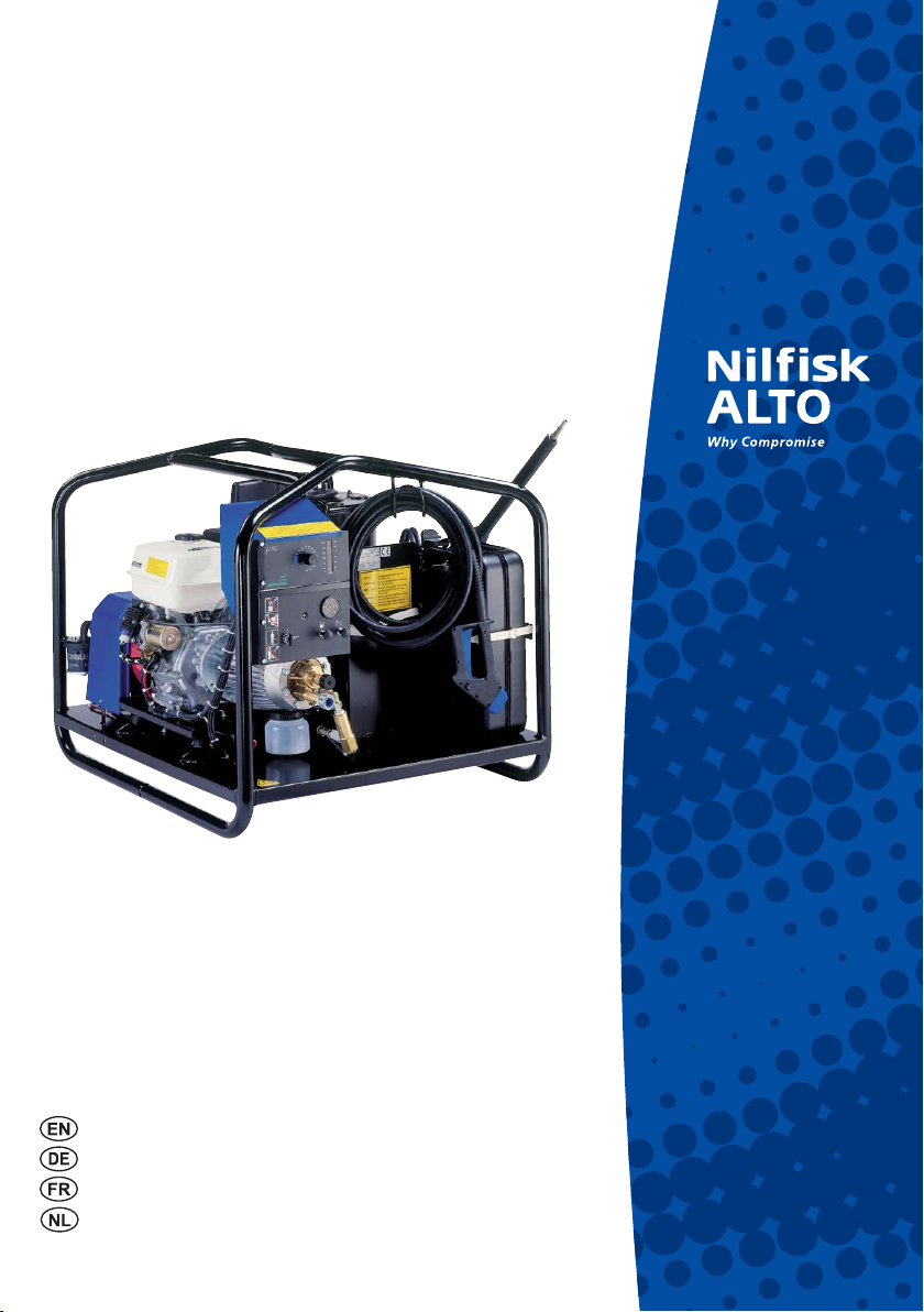
Designations EN
(see drawings inside back cover)
1. Water inlet and fi lter (quick-coupling for sup ply
hose)
2. Pump oil level inspection and fi ll cup
3. Oil drain plug for pump
4. Sludge container
5. Engine oil dipstick and fi ller tube
6. Oil drain plug for petrol engine
7. Petrol fi lling cap
8. Boiler
9. Fan for boiler
10. High pressure outlet (male quick-coupling)
11. Battery, 12V
12. Container rack for detergents
13. Jerrican for heating oil
14. Fuel fi lter
15. Frame lift points
16. Thermostat for temperature regulation
17. Thermometer
18. Key for electric start
19. Fuel cock
20. Choke control
21. Pressure gauge for working pressure
22. Knob for adjustment of water volume
23. Fuse (protection of electronic unit ) rating 1.25AT
and RESET button
24. High pressure steam hose
25. Male coupling
26. Quick coupling
27. Valve for pressure regulation
28. Release trigger
29. Standard double spray lance
30. Low pressure nozzle
31. High pressure nozzle
32. Spray handle
33. Safety knob for release
34. Drain plug for coil
35. Model tag
36. Suction hose with fi lter
Nilfi sk-ALTO environmental policy
Nilfi sk-ALTO has a strong commitment to and constantly
works towards a cleaner and improved world. Nilfi sk-ALTO’s en vi ron men tal concern has led to several awards
in recognition of our contribution to an improved environment. We con stant ly review all aspects of our business
from production facilities, to our products and their packaging.
Nilfi sk-ALTO:
Reuses all water which is used in product testing.
Ensures every plastic component is recyclable.
Produces packaging using whereever possible recyclable
cardboard.
United Kingdom: Health and safety at Work Act 1974 Guidance Note P.M. 29
It has always been the Nilfi sk-ALTO policy to ensure that all Nilfi sk-ALTO products are safe and without risk to health or safety when
properly used.
Nilfi sk-ALTO always endeavour to provide customers with every available item of information on the product they are using by the
issue of descriptive instruction man u als, literature and brochures which are constantly being updated and reviewed.
If you have any doubts or problems please do not hesitate to contact Nilfi sk-ALTO Customer Services on 01768 868995 or write to
Nilfi sk-ALTO Consumer Products, Gilwilly Industrial Estate, Penrith, Cumbria, CA11 9BN.
1
Page 3
1.0 Survey of models EN
1.1 Model tag
This petrol driven hot water cleaner has the model
des ig na tion Contractor/Contractor Master.
The model designation appears from the text on
the control panel and the model tag.
The tag pro vides the following details:
1. Model designation
2. Nilfi sk-ALTO no.
3. Nozzle
4. Heating power
5. Pump pressure
6. Max. pressure
7. Flow volume
8. Max. temperature
9. Pump pressure
0
0MAX
1
4MAX
88K788(0
-ADEIN$ENMARK
XXXXXXXXXXXXXXX
8888
BAR-0A
BAR-0A
LMIN
²#
88888
88888
88
88
88K7
#/.42!#4/2-!34%2
88888
88888
88
88
)08
XXXXXXX
10. Max. pressure
11. Flow
12. Max. temperature
13. Power absorption
14. Approval
15. Serial number, week and year
1.2 Technical data
Model Contractor Contractor Master
Max pressure, inlet water psi/bar 145/10 145/10
Pre-priming, max suction height ft/m 16/5 16/5
Max temp., inlet water °F/°C 95/35 95/35
Water temperature, adjustable °F/°C 86-302/30-150 86-302/30-150
Heat rating Kcal/h/ kW 1053/71 1053/71
Petrol engine, type Honda GX340LXE Honda GX390LXE
Rated output HP/kW 11/8.2 13/9.6
Petrol consumption at max pressure USgph/ l/h 0.9/3.5 1/3.7
Petrol tank, capacity USg/l 10.6/40 10.6/40
Fuel consumption at Dt = 50°C USgph/ l/h 1.5/5.6 1.6/5.9
Jerrican, capacity USg/l 5/20 5/20
Start system Electric start Electric start
Battery V/ah 12/50 12/50
Spray lance:
Spray angle h.p./l.p degrees 15/65 15/65
Nozzle type 05 - yellow 05 - yellow
Thrust, max kp/N 4.1/40.2 4.8/47
Sound power level L
Sound pressure level L
Data at 12°C inlet water. We reserve the right to make alterations.
according to ISO 3746: 96.4 dB(A).
WA
measured in accordance with ISO 11202 [DISTANCE 1m] [FULL LOAD]: 110 dB(A).
pA
2
Page 4
2.0 Instructions for use Safety precautions and warnings EN
Before starting up your high pressure washer for the fi rst time, you must read through the following sec tions: 2.0 Instructions for use and 3.0 Operating instructions and follow all instructions to ensure the
pro tec tion of user, surroundings and machine. Upon the unpacking of your machine please check for any
defects. If you fi nd any, we kindly ask you to contact your Nilfi sk-ALTO distributor.
2.1 Operation
This machine produces a high pressure jet of a high temperature and operation contrary to the in struc tions
can cause severe injury!
For your own and the safety of others the following precautions should always be observed:
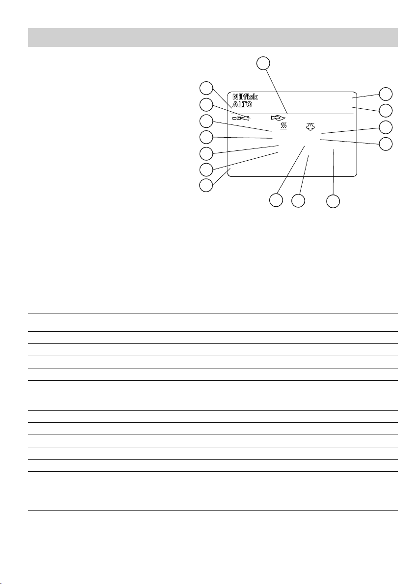
1. WARNING! Never direct the water jet towards people, pets, electric wiring, or the mac hi ne
itself.
2. WARNING! Never try to clean clothes or footwear on yourself or other persons.
3. We recommend you to wear goggles during operation.
4. Never work barefoot or wearing sandals.
5. WARNING! Operator and anyone in immediate vicinity of the site of cleaning should take
action to pro tect themself from being struck by debris dislodged during operation.
6. According to regulations persons under the age of 18 must not operate cleaning machines
with a work ing pressure above 70 bar (applies to this machine).
7. Only let instructed personnel operate the machine.
8. Don’t start the machine until the high pressure hose has been correctly mounted.
9. Spray handle and lance are affected by a backward force (thrust) during operation - there fore always hold the spray lance fi rmly with both hands.
10. At intervals the machine should be stopped and the spray handle secured against in ad ver tent use by locking the trigger with the locking device.
11. Only activate the trigger by hand. Never tie it up or fi x it in any other way.
12. Avoid damage to the high pressure hose such as running over by a car, squeezing, pulling, knotting/
kinking etc. and keep it away from oil and sharp or hot objects, as such may cause the hose to burst.
13. Never dismount the high pressure hose when the water tem per a ture is above 50°C (risk of scalding)
or while the machine is in op er a tion. Disconnect the cleaner and the water con nec tion and
activate the spray handle before dis mount ing the high pressure hose.
14. Never use the machine in an environment where there could be a danger of ex plo si on.
15. WARNING! High pressure hoses, nozzles, spray handle and connections are important for
safety when operating the machine. Only use the high pressure steam hoses (with an im print ed max tem per a ture of 150°C), nozzles and con nec tions pre scri bed by Nilfi sk-ALTO.
16. For safety reasons only use original Nilfi sk-ALTO accessories and spare parts.
17. In icy conditions never start the cleaner until machine, hoses and accessories have thawed. Otherwise
the machine could be damaged.
18. The cleaner must not be covered during operation.
19. WARNING! The fl ue gases of the motor and the boiler contain poisonous carbon monoxide. Avoid
in ha la tion of ex haust gaes. Never run the ma chine in a closed room.
20. WARNING! Keep children and pets away from the machine during operation. There is a risk of burns.
21. WARNING! The muffl er gets warm during operation and will remain warm for a while after the motor
has been stopped. Be careful not to touch the muffl er while warm.
22. WARNING! Use of a wrong fuel in the boiler may be harzardous.
23. Be aware that boiler and the Honda engine use different fuels.
3
Page 5

Safety precautions and warnings EN
* Refuel in a well-ventilated area with adequate ventilation and always with the engine stopped.
* It is not allowed to smoke when refi lling with gasoline.
* Do not overfi ll the tank. Make sure that the fi ller cap is closed securely.
* Avoid spilling gasoline when refi lling. If gasoline nevertheless is spilled, the engine must not be started
* If the machine is placed in a trailer, any gasoline spillage must be removed before restar ting the ma-
* Never use an open fl ame near the machine.
* The battery emits explosive gases. Avoid sparks and open fl ames. Make provision for adequate ven ti -
* Always place the machine at a distance of at least 1 m from buildings or equipment during operation.
* Never place infl ammable products such as petrol and matches etc. close to the ma chine during ope ra ti on.
* Never place the machine in the immediate vicinity of sources of heat (gas burners, heaters etc.).
* Always let the engine cool before transporting it or setting it aside to avoid burns and to reduce the risk
DANGER OF EXPLOSION!
before the spilled gasoline has been removed.
chine.
la ti on during recharge in closed rooms.
DANGER OF FIRE
of fi re.
2.2 Safety devices on the machine
Circulation valve (safety valve)
The pressure side of the high pressure pump is fi tted with a circulation valve (safety valve). This valve
cir cu lates the water back to the suction side of the pump when the spray handle is closed or if a nozzle
is blocked. The circulation valve has been constructed as a safety function ensuring that the pres sure will
never exceed the working pres sure by more than 25 bar. At this pres sure the circulation valve will au to mat i cal ly switch from high pressure to cir cu la tion mode.
Never let the machine run for more than 5 min. upon release of the spray handle as it may be damaged.
The valve has been adjusted and sealed from the factory. This adjustment must not be changed! The
cir cu la tion valve ensures that the machine becomes devoid of pressure when it is stopped.
Motor protection
The engine will automatically stop if the oil level is insuffi cient. The engine can be restarted when having
been re fi lled with oil.
2.3 General
1. It is not allowed to clean asbestos-containing surfaces with high pressure, unless using spe cial equip ment.
2. Persons under the infl uence of alcohol, drugs and medicine should not operate the machine.
3. When using detergents the enclosed in struc tions should always be strictly observed.
4. Don’t use the machine if important parts of the equipment are damaged - i.e. safety devices, high pres-
sure hoses, spray handle, cabinet.
5. WARNING! Battery acid contains corrosive sulphuric acid. Avoid contact with skin, eyes and clothes.
Even through your clothes the sulpuric acid may cause etching. If you get acid on your skin, fl ush with
suffi cient water. If you get battery acid in your eyes, fl ush carefully with water for at least 15 minutes and
send for a doctor.
6. WARNING! Battery acid is toxic. If battery acid is swallowed: Drink a lot of water or milk. Then more milk,
whipped eggs or vegetable oil and send for a doctor immediately.
7. The most effi cient cleaning is obtained if you adjust the distance to the surface which is to be cleaned.
Thus you will also avoid damaging the surface.
4
Page 6
3.0 Ope ra ting instructions EN
3.1 Connections
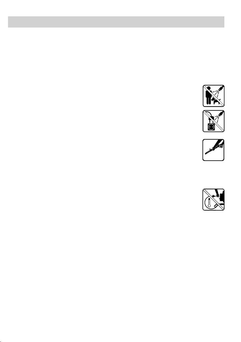
3.1-1 High pressure hose
Only use Nilfi sk-ALTO high pressure
10
24
The high pressure hose (24) with imprinted max working pres su re and temperature (150°C) should be
attached to outlet socket (10) by quick coupling.
3.1-2 Water connection
steam hoses with an imprinted max
tem pe ra tu re of 150°C.
Max length of extension hose: 50 m.
1
The water supply system must supply the water volume stated in section “1.2 Tech ni cal data”.
Let water run through the inlet hose to remove any impurities.
Attach the water inlet hose to the water connection (1).
If there is a risk of impurities (i.e. running sand) in the inlet water, an external water fi lter should be mount ed beyond the internal fi lter. Please contact your Nilfi sk-ALTO distributor for further in for ma tion.
NOTE: Connection to the public mains according to regulations.
Min length of hose: 6 m. 3/4".
Clean water inlet fi lter (1) at monthly
intervals.
Max water pressure 10 bar.
3.1-3 Fuel fi lling for boiler
13
Fuel for the boiler is fi lled into the jerrican (13). Capacity of tank: 20 l. Only use heating oil or diesel oil.
WARNING: NEVER fi ll petrol into this jerrican!
Only use heating oil or diesel oil.
WARNING! Use of a wrong fuel can be
hazardous!
Capacity of tank: 20 l.
5
Page 7
Operating instructions EN
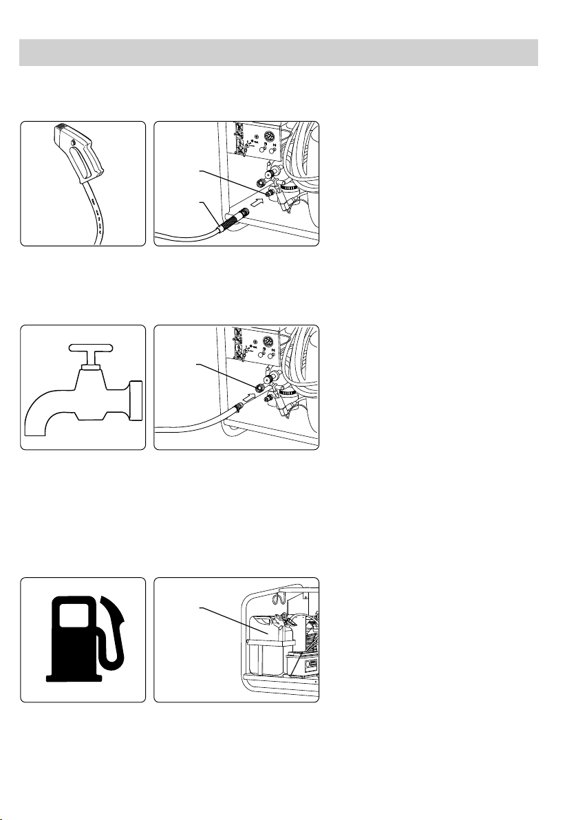
3.1-4 Fuel fi lling for the Honda engine
WARNING!
7
Petrol for the Honda engine is poured into the petrol tank (7). Only use pure petrol.
Always stop the engine and let it cool for at least two minutes before fi lling with petrol.
Avoid spilling petrol. If petrol nevertheless is spilled while refi lling, the engine must not be started before
the spilled petrol has been removed.
If the machine is placed in a trailer, any petrol spillage must be removed before restarting the machine.
It is forbidden to smoke while refi lling with petrol.
Also read the instructin manual for the Honda engine.
Stop the engine and allow it to cool for
at least two minutes before fi lling with
pe trol.
Check the Honda manual for the petrol
octane specifi cations.
Only use pure petrol in the Honda
engine.
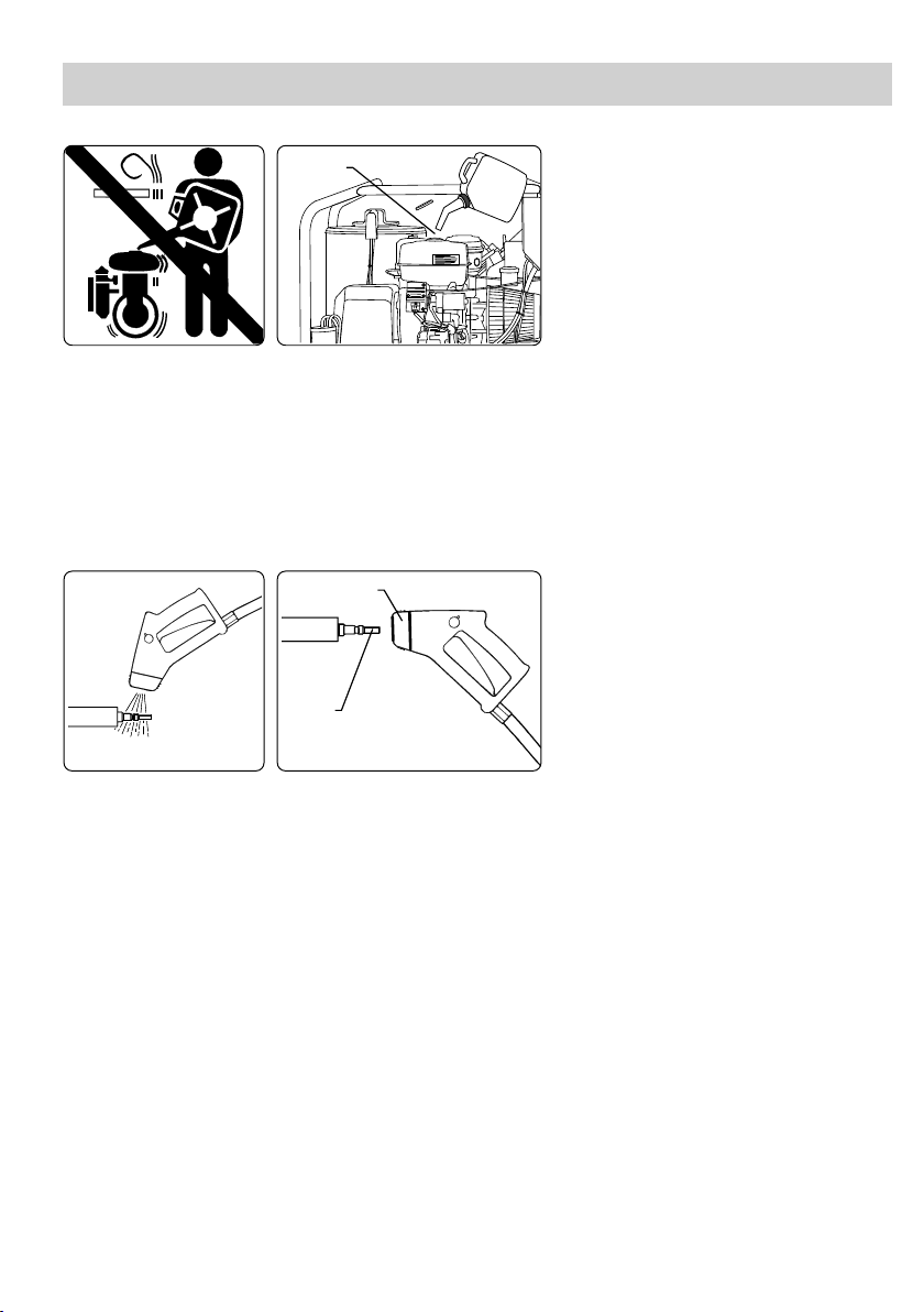
3.1-5 Spray handle - ac ce sso ri es
26
Clean nipple of any impurities each time
the spray lance has been dismounted.
25
Pull for ward the grey quick coupling trig ger of the spray handle (26).
Insert the nipple of the spray lance (25) in the quick coupling and release the trigger.
Pull forward the spray lance or any other accessory to ensure correct mounting before starting the clean er.
Max thrust of spray handle and lance - see section “1.2 Technical data”.
6
Page 8

Operating instructions EN
150
130
110
90
70
50
˚C
300
265
230
195
160
125
˚F
TEMP
˚C
140
130
110
90
150
120
100
80
7050
60
40
30
16
1918
20
3.2 Starting-up procedure
Check oil
Turn the thermostat to the BLUE fi eld.
Turn to position “START”.
Check that the oil in the oil reservoir (2) is between the MIN and the MAX markings. Oil type: Nilfi sk-ALTO
Pump Oil 100.
Check the oil level on the Honda engine (5). Oil type: Choose oil type in accordance with the instructions in
the Honda manual.
Open the petrol cock (pos. 19) by pulling the control knob out. Activate the choke (pos. 20) if necessary by
pulling the control knob out.
Turn the temperature control (16) to the BLUE fi eld. Make sure that the high pres sure hose has been cor rect ly mounted.
Start the Honda engine as described in the enclosed operating instructions.
The key for the electric start has the following three positions:
1: “O” off
2: “I” run
3: “Start” - the key will return to position 2 when released
Gradually push in the choke control if having been used.
3.3 Operation
33
Always hold the spray lance with both
hands!
Always lock the spray handle when the
cleaner is not in operation.
28
Activate the high pressure washer by releasing the trigger of the spray handle (28). When starting up the
machine the pressure may be unsteady because of air in the pump system. After a short time the air will
escape from the system and the pressure will become steady.
When the engine has been warmed up, check that the max. working pressure does NOT exceed the max i mum allowable pump pressure (see section "1.2 Technical data"). This can be taken from the pres sure
gauge (pos. 21).
Do not let the machine run for more than 5 minutes once the spray handle has been released (the
pump then circulates the water internally and the machine will overheat unless stopped after 5 min utes).
When the cleaner is not in use, secure the spray handle by turning the safety knob (33) into pos. 0.
7
Page 9

Operating instructions EN
150
130
110
90
70
50
˚C
300
265
230
195
160
125
˚F
TEMP
˚C
140
130
110
90
150
120
100
80
7050
60
40
30
16
17
22
3.4 Temperature control
Cold water mode 0 - 50°C
Hot water mode 50 - 95°C
Steam mode 95 - 150°C
Adjust the temperature control (16) to the required temperature.
Indicator lamps on the temperature dis play (17) show the actual temperature of the outlet water.
Cold water mode: Upon the starting-up procedure the machine is immediately ready for cleaning with
cold water.
Hot water mode: Adjust the tem per a ture control (16) to the required tem per a ture, 30-95°C.
Steam mode: Screw the valve for reg u la tion of the water volume (22) home (clock wise), and adjust
the temperature control (16) to the required tem per a ture, 95-150°C.
Note: The max temperature of 150°C can only be reached with the re duc tion valve
(27) of the spray lance ad just ed to high pressure (turn clockwise until stop).
IMPORTANT: When adjusting to tem per a tures above 95°C the valve for reg u la tion of the water volume
(22) must be screwed completely home (clock wise) upon which the temperature control (16) can be
adjusted to the re quired tem per a ture, 95 - 150°C.
3.5 Spray lance, regulation of pressure and water volume
27
High pressure operation
The max working pressure of the ma chine is reached when the pressure reducing valve (7) is completely
closed (B) and the valve for regulation of the water volume (22) is quite open (turned in the direction of the
arrow). In this position only the high pressure nozzle is used - high pressure mode. The water volume is
infi nitely variable between min and max output.
When the spray handle is inactivated, screw the valve for regulation of the water volume (22) home (in the
opposite direction of the arrow). This corresponds to a working pressure of 30 bar and a water volume of
approximately 8 l/min. If you want to increase the water volume, turn the valve in the direction of the arrow
until the re quired volume has been reached. 1 turn gives an increase of approx. 40 bar pressure.
Low pressure operation
If a completely reduced pressure is required, open the reduction valve (A) completely. The nozzle pres sure
will then be approx. 5 bar. In this position both spray lances are used - low pressure mode.
Turn pressure reducing valve:
Clockwise (B): high pressure
Counter clockwise (A): low pressure
22
The spray lance features 2 nozzles; a
high pressure nozzle and a low pressure
nozzle.
8
Page 10

Operating instructions EN
150
130
110
90
70
50
˚C
300
265
230
195
160
125
˚F
TEMP
˚C
140
130
110
90
150
120
100
80
70
50
60
40
30
16
1918
17
3.6 Stop - dismounting of high pres su re hose
Danger of scalding!
Never dismount the high pressure hose
when the water temperature is above
50°C.
If the machine is set aside immediately after hot water or steam operation, it should be cooled down in
"cold water mode" at fi rst until the tem per a ture is below 50°C.
Turn the temperature control (16) to the blue fi eld for cold water and activate the spray handle until the
tem per a ture (17) is below 50°C.
Then turn off the water supply and stop the Honda engine by turning the start/stop button (18) to position
O.
Close the petrol cock (pos. 19). (See instructions for the Honda engine).
Now the high pressure hose can be dismounted.
3.7 Transport directions
15 15
For lifting by crane, use lifting straps!
When lifting the machine by forklift truck, be sure the forks extend completely under the machine to pre vent tipping. When lifting by tackle/crane a sling may be wrapped around the upper frame tubes (15) for
lifting.
Ensure that no persons are under or near the machine when lifting it.
Always fasten the machine securely during transport.
9
Page 11

Operating instructions EN
3.8 Storage - frost pro tec tion
Frost-free room or anti-freeze!
34
We recommend you to store the machine in a frost-free room between the cleaning tasks. The machine
must be emptied of water prior to storing for a longer period. This is done in the following way:
1. Detach water hose. Dismount spray lance and empty it of water.
2. Turn the thermostat to the BLUE fi eld, start the machine, and let it run with activated spray handle until
all water has run out. Then empty the coil by unscrewing the drain plug (34).
FROST PROTECTION
If the store room is not frost-free, the ma chine should be protected with an an ti freeze. The frost protection
is reached by following the two points above, screwing the drain plug in again and then do the following:
1. Place the inlet/suction hose in a bucket containing approx. 8 l anti-freeze.
2. Draw in the anti-freeze by activating the spray handle. Activate the spray handle 2-3 times while placing
it above the bucket with anti-freeze so that the anti-freeze can circulate.
3. Remove the inlet hose from the bucket, activate the spray handle and the rest of the anti-freeze is lead
back into the bucket.
NB! After repeated use the anti-freeze will be diluted with water and thus loose its anti-freeze effect.
10
Page 12

4.0 Fields of application and work ing methods EN
4.1 Fields of application
The most important fi elds of application for this product are:
Transport Cleaning of trucks, buses, cars, engine rooms, etc.
Building and construction Building renovation, cleaning/degreasing of ve hi cles, equipment,
Industry Degreasing and cleaning of machines, workpieces, and vehicles.
Service Cleaning of vehicles and degreasing tasks.
4.2 Working pressure
The high pressure washer may be used with high or low pressure at your own option. At the standard
spray lance the working pressure is adjusted by tur ning the reduction valve.
Low pressure Is fi rst and foremost used for application of detergents and for washing
High pressure Is used for cleaning.
Intermediate pressure As an example it may be used for the cleaning of surfaces, which can-
4.3 Detergents
As standard the machine is delivered without a detergent injector.
Detergent should not be added to the inlet water and thus pass through the pump. If you want to use de ter gents these should be added through an external injector (see accessories catalogue).
The most effi cient cleaning is obtained when using detergents in conjunction with high pressure cleaning.
For that purpose Nilfi sk-ALTO can offer you a series of products specially developed for high pressure
cleaning, e.g.:
buildings, etc.
off.
not stand a too powerful water jet, i.e. soft surfaces.
Cleaning of vehicles, machines, etc. Disinfection
Degreasing of workpieces Maintenance of the high pres sure washer
Descaling
The products are water-based, without phosphates, and the applied tensides (surface active substances)
comply with the present requirements for easy biodegradability.
Contact your Nilfi sk-ALTO distributor for directions as to which product(s) will fulfi ll your requirements.
The method of application and the dosage of the individual products appear from the product labels or the
data sheet.
NOTE! Certain organic solvents are aggressive to rubber and plastics used in high pressure hoses and
must therefore not be used. Using detergents outside the range from 4.0 - 10.0 pH will reduce the life of
the equip ment.
Change from application of detergent under low pressure to cleaning under high pressure is simply ef fect ed by regulating from “low pressure mode” to "high pressure mode" on the spray lance.
For foam cleaning mount the special foam injector between the high pressure washer and the high pres sure hose. Insert the suction hose of the injector into the foam detergent. Attach the foam lance to the
spray handle and now foam can be applied. Upon application detach the foam injector and replace the
foam lance by a spray lance and you are ready for cleaning.
11
Page 13

Fields of application and working methods EN
4.4 Working methods
Your high pressure washer has been developed for cleaning according to the so-called "2-step method".
STEP 1 Application of detergent
STEP 2 High pressure cleaning
In practice the working process is laid down in accordance with the actual job, but as a starting point the
fol low ing working method can be described for a job:
1. Apply detergent under low pressure. The dosage is chosen according to the job which is to be
carried out, and the adjustment is made on the control knob on the injector.
2. Await acting time. Let the detergent act on the dirt/surface for a short time prior to pressure clean ing
- usually a few minutes.
3. High pressure cleaning. Clean all surfaces under high pressure.
4. Rinse afterwards, if necessary. To make sure that residual impurities are removed from the sur face.
In connection with the working process the optimum cleaning will be reached by following these 3 pieces
of advice:
Advice no. 1
When using a detergent, always apply it on a dry surface. If the surface is rinsed with water at fi rst, it may
be diffi cult for it to absorb the detergent, and the result is a reduced effect of the detergent.
Advice no. 2
When applying a detergent on large vertical surfaces (i.e. the sides of a truck) work from below and up wards. Thus you will avoid detergent running off the surface through grooves and dark streaks appearing
on the surface whilst cleaning.
Advice no. 3
During the high pressure cleaning you should work so that the high pressure water does not run over the
surface which has not been cleaned yet. This is to ensure that there is suffi cient detergent on the surface
when the high pressure water hits the surface.
For certain cleaning tasks it may be an advantage to apply detergents for high pressure operation - i.e. for
the dewaxing of cars.
5.0 Pre-priming
The pressure washer is self-priming, and the water can be taken from a tank, a stream or the like. The
suc tion height depends on the water temperature. Max. suction height of 5 m is reached with cold water up
to 12°C. The pump and the inlet hose must be primed with water before starting up.
If there is a risk of impurities (such as running sand) in the Intel water, an external fi lter must be mounted
beyond the internal fi lter. Please contact your Nilfi sk-ALTO distributor for further in for ma ti on.
12
Page 14

6.0 Functional description EN
6.1 General description
The water passes from the quick coupling (a) through a water fi lter (b) into the high pressure pump (c).
The high pressure water leads through the discharge system of the pump where the safety and circulation
valve (d) is situated. Then it passes the fi rst fl ow switch (e) to the non-return valve with throttle (f), through
the second fl ow switch (g) and en ters the boiler (h). Here the water is heat ed to the required temperature. After the boiler the hot high pressure water pass es the tem per a ture sensor (i), through the outlet
quick connector (j) to the spray han dle (k) and the spray lance (l). The fuel is drawn from the fuel tank (m)
through the fuel fi lter (n) by the fuel pump (o). Now the pump leads fuel through the solenoid valve (p) to
the noz zle (q) where it is ig nit ed.
The combustion in the boiler is monitored by the fl ame sensor (w) and is supplied with air from the fan (r)
which together with the high pressure pump (c) are driven by the petrol engine (s).
6.2 High pressure pump
On the pressure side the high pressure pump features a circulation valve (d). This valve leads the water
back to the suction side of the pump when the spray handle is closed or if a nozzle is blocked. The circulation valve also functions as a safety valve and has been adjusted to open approx. 25 bar above the work ing pressure. The valve has been adjusted and sealed from the factory. This adjustment must NOT be
changed! When the machine stops it is automatically devoid of pressure.
6.3 Petrol engine
A description of the operation/maintenance instructions for the Honda engine will be found in the Honda
manual provided with the machine. Please read this before starting up. The throttle limit of the engine has
been adjusted by Nilfi sk-ALTO so that the max. number of revolutions corresponds to the max. pressure of
the pump (see section "1.2 Technical data"). The adjustment is sealed and must NOT be changed.
6.4 Burner system - control system
The burner system is surveyed and controlled by an electronic control unit which includes a thermostat,
fl ow switches to control the water fl ow and a sensor to monitor the fl ame.
The water temperature is controlled by the temperature sensor (i) which regulates the fuel supply for the
burner through the solenoid valve (p). As the burner is only allowed to operate when there is a water fl ow
in the system (i.e. when the spray handle is activated) the machine features two fl ow controls (e-g) which
con trol the fuel supply through the electronic control unit. When the fl ow in the system is interrupted, the
fl ow switch es are activated and the fuel supply will stop. When the water fl ow repeats, the fl ow switches
are re ac ti vat ed and reallow the fuel supply. Safety circuits in the electronic control unit survey that both fl ow
switch es are activated. Thus the fuel supply is interrupted when only one of the fl ow switches are activated.
When the water fl ow is repeated the control unit only allows the fuel supply if both fl ow switches have been
activated.
The fl ame sensor is a separate circuit stopping the machine if there is no fl ame in the burner in hot water
or steam mode.
It is important for the life of the fuel pump that the machine is not allowed to run in the hot water or cold
water mode with empty fuel tank. If the burner stops working unexpectedly, check the fuel level in the tank
and refi ll if necessary.
NB! Changes of the electrical coupling of the machine are not allowed.
13
Page 15

Functional diagram EN
a. Quick coupling, inlet
b. Water fi lter
c. High pressure pump
d. Circulation valve
e. Flow switch
f. Non-return valve with throttle
g. Flow switch
h. Coil
i. Temperature sensor
j. Quick coupling, outlet
k. Spray handle
l. Spray lance
m. Fuel tank
n. Fuel fi lter
o. Fuel pump
p. Solenoid valve
q. Burner system - nozzle
r. Fan
s. Petrol engine
t. Safety valve
u. Pressure gauge
v. Regulation of water volume
w. Flame sensor
The following sensors are built into the system:
- Flow switches (e-g)
Ensure that there is a water fl ow through the boiler, before it can be ignited.
Allows the solenoid valve (p) to open.
- Flame sensor (light sensor) (w)
Surveys that there is a combustion in the boiler when fed with fuel, and that the combustion will stop
when the fuel supply is cut off.
- Temperature sensor (i)
Measures the temperature of the high pressure water from the boiler. Dependent on higher or lower
tem per a ture the burner will ignite or turn out.
14
Page 16

7.0 Maintenance EN
7.1 General
To ensure that your Nilfi sk-ALTO high pressure washer is always in an operational condition it is advisable
to have it checked by a Nilfi sk-ALTO service technician at regular intervals.
However, it applies to the most exposed components that a minimum of maintenance ensures a pro longed
and problem-free operation. Therefore it will also be a good idea to make a habit of the following:
z Before mounting the water hose and the high pressure hose the quick couplings should be
cleaned of dust and sand.
z Before mounting spray lance or any other accessory on the spray handle, the machine should
be started and the quick coupling cleaned of dust and sand.
z The water fi lter should be cleaned once a month or more frequently as the occasion requires.
z We recommend you to store the machine in a frost-free room. If by mistake the machine
freezes up, it must not be started. Let machine, hoses and accessories thaw up before starting
up.
If the room is not frost-free the machine should be protected with an antifreeze.
z Replace fuel fi lter (14) once the year or more frequently as the occasion requires.
7.2 Oil
Oil change - pump
The oil shold be changed after each 1000 hours’ use.
Remove the cover of the oil reservoir (2). Unscrew the drain plug (3). Allow the oil to run out and clean the
drain plug of impurities. Screw in the plug and refi ll the pump with fresh oil through the oil reservoir. Holds
approx. 1 l.
From Nilfi sk-ALTO the pump is fi lled with zincless hydraulic oil - Nilfi sk-ALTO Pump Oil 100. When refi lling
and chang ing the oil this or an oil with the following specifi cations should be used:
ISO no 100
Viscosity index (VI) min 130
Pour point below -30°C
Sludge container
The used oil is caught in a sludge container (4). The container should be emptied before it is full; this oil
must not be reused in the pump.
Oil change - Honda engine
Refer to the Honda engine manual for maintenance and oil change requirements. Carry out fi rst oil change
after 20 hours’ operation and then every 100 hours. Not less than once every six months, how ev er.
PROTECT THE ENVIRONMENT
Waste oil and oil sludge must be removed as laid down in the instructions.
7.3 Water fi lter
To avoid debris entering the high pressure pump, a water fi lter is fi tted at the water inlet (1). Dependent on
the purity of the water this fi lter will have to be cleaned once the month or more frequently as the oc ca sion
re quires.
The fi lter can be removed when the quick coupling has been unscrewed.
7.4 Fuel fi lter
A fi lter (14) between the fuel tank and the fuel pump prevents impurities from penetrating the fuel pump.
The fi lter unit should be changed dependent on the purity of the fuel. A yearly change of the fi lter is rec om mend ed.
15
Page 17

2
4
3
2. Cover of oil reservoir
3. Oil drain plug
4. Sludge container
14. Fuel fi lter
34. Drain plug for coil
16
1434
Page 18

Maintenance EN
7.5 Descaling of coil
After a period of operation depending on the hardness of the water scale deposits will begin to ac cu mu late
in the heating coil. These deposits will reduce the effect of the water heating system and increase the fuel
consumption. The machine should therefore be descaled regularly. If the machine adjusted on max. water
volume will not heat cold water (8°C) to 70°C within three minutes, the burner or the coil requires servicing
or descaling.
Descaling as follows:
1. Detach high pressure hose.
2. Insert the inlet hose in a container with descaler, Nilfi sk-ALTO Stonex and water in the ratio 1:10.
3. Start the machine in cold water mode.
4. Stop the machine when the water escaping the outlet socket has been coloured by the descaler.
Warning: The mixture may be caustic!
Do not on any occasion empty the container to prevent air getting into the system.
5. Let the machine rest for 20 minutes.
6. Start the machine and pump the used solution into a container for proper disposal.
7. Immediately attach the water inlet hose to the water supply and turn on the tap.
8. Start the machine and let it run 5 - 10 minutes to have the descaler out of the system.
9. If required, repeat the procedure from item 3 - 8.
Note! The descaling should always be carried through in ac cord ance with the instructions on the descaler
product.
7.6 Cleaning of high pressure no zz le
A clogging up in the nozzle causes a pump pressure which is too high and cleaning is im me di ate ly re quired.
1. Stop the cleaner and detach the spray lance.
2. Carefully clean the nozzle.
IMPORTANT: ONLY use the cleaning tool when the spray lance is de tached!
3. Flush the spray lance backwards with water.
4. If the pressure is still too high, repeat items 1 - 3.
17
Page 19

8.0 Trouble shooting chart EN
You have chosen a quality product and therefore deserve the best serv ice. To avoid unnecessary dis ap point ments, you should check the following before contacting the nearest Nilfi sk-ALTO service or gan i sa tion:
Fault Cause Cor rec tion
Machine will not start Insuffi cient petrol supply Refi ll petrol tank
Battery run down Recharge the battery *)
Pump frozen up Let the pump thaw
A fuse has blown Replace fuse or press the RESET button
(23)
Working pressure too high Nozzle partly clogged up Clean the nozzle (see section 7.6)
Working pressure too low Valve for regulation of water Completely open the valve for regulation of
volume not adjusted to max water volume. Turn in the direction of the
water volume arrow.
Nozzle damaged Replace nozzle.
Motor speed too low Contact Nilfi sk-ALTO servicing department
Working pressure Air in the pump Repeat venting. Check that the dosing valve
fl uctuating (22) is completely closed.
Insuffi cient water supply from Detach the water inlet hose and check the
the water works water volume (see section 1.2).
NB! Avoid long thin hoses (min 3/4").
In suction mode Excessive head or See section 5.0 Pre-priming
excessively hot water
Water inlet screen clogged up Clean the fi lter (see section 7.3).
No working pressure Nozzle clogged up Clean the nozzle (see section 7.6).
No inlet water Check the water connection.
Hoses / spray lance frozen up Let hoses / spray lance thaw.
Burner does not ignite Lack of fuel Refi ll with fuel.
Fuel fi lter clogged up Replace fuel fi lter.
No fl ame Replace fuel fi lter (see section 7.4).
Poor heating Scale deposits in coil Descale coil (see section 7.5).
Should other malfunctions occur than those mentioned above, please contact the nearest Nilfi sk-ALTO
service organisation.
NB: To avoid damage to the electronic systems, the battery connecting cables must be removed when
recharging the battery.
18
Page 20

EC Declaration of Conformity
Nilfi sk-ALTO, Division of Nilfi sk-Advance A/S, In du stri vej 1,
• • • High pressure washer • • •
type : CONTRACTOR MASTER
is in conformity with the provisions of the following di rec tives as amended:
2006/42/EC, 2006/95/EC, 2004/108/EC
and furthermore declares that the following (parts/
clauses of) har mo nized standards have been applied:
EN ISO 12100-1 (2004), EN ISO 12100-2 (2004)
EN 55014-1 (2006), EN 55014-2 (2001)
and that the following (parts/clauses of) national standards have been used:
IEC 60335-2-79 (2007)
DK-9560 Had sund
herewith declares that
EG-Konformitätserklärung
Nilfi sk-ALTO, Division of Nilfi sk-Advance A/S, In du stri vej 1,
Typ : CONTRACTOR MASTER
konform ist mit den einschlägigen Bestimmungen fol gen der EG-Richtlinien inklusive deren Änderungen:
2006/42/EC, 2006/95/EC, 2004/108/EC
Des weiteren erklären wir, daß folgende harmonisierten
Normen (oder Teile/Klauseln hieraus):
EN ISO 12100-1 (2004), EN ISO 12100-2 (2004)
EN 55014-1 (2006), EN 55014-2 (2001)
sowie folgende nationale Normen (oder Teile/Klauseln
hieraus) zur Anwendung gelangten:
IEC335-2-79 (2007)
DK-9560 Had sund
erklärt hiermit, daß dieses Produkt:
• • • Hochdruckreiniger • • •
Hadsund, Denmark 01.01.2009
Issue place and date Anton Sørensen
General Manager, Technical Operations EAPC
Déclaration CE de Conformité
Nilfi sk-ALTO, Division of Nilfi sk-Advance A/S, In du stri vej 1,
DK-9560 Had sund
déclare ci-après que le produit:
• • • Nettoyeur haute pression • • •
type : CONTRACTOR MASTER
est conforme aux dispositions des directives CEE
suivantes et les amen de ments futurs:
2006/42/EC, 2006/95/EC, 2004/108/EC
et déclare par ailleurs que les (parties/paragraphes)
suivants des normes harmonisée ont été appliquées
EN ISO 12100-1 (2004), EN ISO 12100-2 (2004)
EN 55014-1 (2006), EN 55014-2 (2001)
et les (parties/paragraphes) suivantes des normes
nationales:
IEC335-2-79 (2007)
Hadsund, Denmark 01.01.2009
Lieu et date Anton Sørensen
General Manager, Technical Operations EAPC
Hadsund, Denmark 01.01.2009
Ort, Datum der Ausstellung Anton Sørensen
General Manager, Technical Operations EAPC
EEG Conformiteitsverklaring
Nilfi sk-ALTO, Division of Nilfi sk-Advance A/S, In du stri vej 1,
type : CONTRACTOR MASTER
voldoet aan de bepalingen van de volgende EEG-richtlijnen in clu sief de na ge ko men wijzigingen ter uitvoering
van deze richtlijn:
2006/42/EC, 2006/95/EC, 2004/108/EC
en verklaart voorts dat de volgende (onderdelen van)
geharmoniseerde normen zijn toegepast:
EN ISO 12100-1 (2004), EN ISO 12100-2 (2004)
EN 55014-1 (2006), EN 55014-2 (2001)
en volgende (onderdelen van) national technische normen en specifi caties zijn gebruikt:
IEC335-2-79 (2007)
Hadsund, Denmark 01.01.2009
Plaats en datum van publikatie Anton Sørensen
General Manager, Technical Operations EAPC
DK-9560 Had sund
verklaart hermede dat het produkt::
• • • Hogedrukreiniger • • •
Page 21

8
72
14 9 6 5 3 10
23
14
4
1
15 15
341113
31
30
27
21
18
29
25
32
24
22
1
10
1
0
4
1
20
19
22
16
17
35
36
Page 22

http://www.nilfi sk-advance.com
HEAD QUARTER
DENMARK
Nilfi sk-Advance Group
Sogne ej 25
DK-2605 Brøndby
Tel.: (+45) 4323 8100
Fax: (+45) 4343 7700
E-mail: mail.com@nilfi sk-advance.com
SALES COMPANIES
ARGENTINA
Nilfi sk-Advance srl.
Edifi cio Central Park
Herrera 1855, Offi ce 604
Ciudad Autónoma de Buenos Aires
Tel.: (+54) 11 6091 1571
Fax:(+54) 11 6091 1575
AUSTRALIA
Nilfi sk-ALTO
48 Egerton St.
P.O. Box 6046
Silverwater, N.S.W. 2128
Tel.: +61 2 8748 5966
Fax: +61 2 8748 5960
E-mail: info@nilfi skalto.com.au
AUSTRIA
Nilfi sk-Advance GmbH
Metzgerstrasse 68
5101 Bergheim bei Salzburg
Tel.: 0662 456 400-0
Fax: 0662 456 400-34
E-mail: info.at@nilfi sk-advance.com
BELGIUM
Nilfi sk-ALTO a division of Nilfi sk-Advance n.v-s.a.
Riverside Business Park
Boulevard Internationalelaan 55
Bâtiment C3/C4 Gebouw
Bruxelles 1070 Brussel
Tel.: (+32) 2 467 60 40
Fax: (+32) 02 466 61 50
E-mail: info.be@nilfi sk-alto.com
CANADA
Clarke Canada
Part of the Nilfi sk-Advance Group
4080-B Sladeview Crescent, Unit 1
Mississauga, Ontario L5L 5Y5
Tel.: (+1) 905 569 0266
Fax: (+1) 905 569 8586
CHINA
Nilfi sk-Advance (Shenzhen) Ltd.
Blok 3, Unit 130 1001 Honghua Road
Int. Commercial & Trade Center
Fuitian Free Trade Zone
518038 Shenzhen
Tel.: (+86) 755 8359 7937
Fax: (+86) 755 8359 1063
CZECH REPUBLIC
ALTO Ceská Republika s.r.o.
Do Čertous 2658/1
193 00 Praha 9
Tel.: (+420) 24 14 08 419
Fax: (+420) 24 14 08 439
E-mail: info@alto-cz.com
DENMARK
Nilfi sk-Advance A/S
Industrivej 1
9560 Hadsund
Tel.: +45 7218 2100
Fax: +45 7218 2105
E-mail: salg.dk@nilfi sk-alto.com
Nilfi sk-ALTO Food division
Division of Nilfi sk-Advance A/S
Blytækkervej 2
9000 Aalborg
Tel.: +45 7218 2100
Fax: +45 7218 2099
E-mail: food.division@nilfi sk-alto.dk
FINLAND
Nilfi sk-Advance Oy Ab
Piispantilankuja 4
02240 Espoo
622 99 06 e (01.2009)
Tel.: +358 207 890 600
Fax: +358 207 890 601
E-mail: asiakaspalvelu.fi @nilfi sk.com
FRANCE
Nilfi sk-ALTO
ALTO France SAS
Aéroparc 1
19 rue Icare
67960 Entzheim
Tel.: (+33) 3 88 28 84 00
Fax: (+33) 3 88 30 05 00
E-mail: info.fr@nilfi sk-alto.com
GERMANY
Nilfi sk-ALTO
Division of Nilfi sk Advance
Guido-Oberdorfer-Str. 10
89287 Bellenberg
Tel.: (+49) (0) 180 5 37 37 37
E-mail: info.de@nilfi sk-alto.com
GREECE
Nilfi sk-Advance SA
8, Thoukididou str.
164 52 Argiroupolis
Tel.: +30 210 96 33443
Fax: +30 210 96 52187
E-mail: nilfi sk-advance@clean.gr
HOLLAND
Nilfi sk-ALTO
Division of Nilfi sk-Advance BV
Camerastraat 9
3322 BB Almere
Tel.: (+31) 36 5460 760
Fax: (+31) 36 5460 761
E-mail: info.nl@nilfi sk-alto.com
HONG KONG
Nilfi sk-Advance Ltd.
2001 HK Worsted Mills Ind’l Bldg.
31-39 Wo Tong Tsui St.
Kwai Chung
Tel.: (+852) 2427 5951
Fax: (+852) 2487 5828
HUNGARY
Nilfi sk-Advance Kereskedelmi Kft.
II. Rákóczi Ferenc út 10
2310 Szigetszentmiklos-Lakihegy
Tel: (+36) 24475 550
Fax: (+36) 24475 551
E-mail: info@nilfi sk-advance.hu
INDIA
Nilfi sk-Advance India Limited
349, Business Point,
No 201,2nd fl oor, above Popular Car World,
Western Express Highway, Andheri ( East),
Mumbai - 400 069
Tel: (+91) 22 321 74592
ITALY
Nilfi sk-ALTO
Divisione di Nilfi sk-Advance A/S
Località Novella Terza
26862 Guardamiglio (LO)
E-mail: d.puglia@nilfi sk-advance.it
JAPAN
Nilfi sk-Advance Inc.
1-6-6 Kita-shinyokohama, Kouhoku-ku
Yokohama, 223-0059
Tel.: (+81) 45 548 2571
Fax: (+81) 45 548 2541
MALAYSIA
Nillfi sk-Advance Sdn Bhd
Sd 14, Jalan KIP 11
Taman Perindustr ian KIP
Sri Damansara
52200 Kuala Lumpur
Tel.: (+60) 3 603 6275 3120
Fax: (+60) 3 603 6274 6318
MEXICO
Nilfi sk-Advance de Mexico, S. de R.L. de C.V.
Prol. Paseo de la Reforma 61, 6-A2
Col. Paseo de las Lomas
01330 Mexico, D.F.
Tel: +52 55 2591 1002 (switchboard)
Fax: +52 55 2591 1002 ext. 229
E-mail: info@advance-mx.com
NORWAY
Nilfi sk-Advance AS
Bjørnerudveien 24
1266 Oslo
Tel.: (+47) 22 75 17 70
Fax: (+47) 22 75 17 71
E-mail: info.no@nilfi sk-alto.com
POLAND
Nilfi sk-Advance Sp. Z.O.O.
05-800 Pruszków
ul. 3-go MAJA 8
Tel.: +48 22 738 37 50
Fax: +48 22 738 37 51
E-mail: info@nilfi sk-alto.pl
PORTUGAL
Nilfi sk-ALTO
Division of Nilfi sk-Advance Lda.
Sintra Business Park
Zona Industrial Da Abrunheira
Edifi cio 1, 1° A
P2710-089 Sintra
Tel.: +35 808 200 537
Fax: +35 121 911 2679
E-mail: mkt@nilfi sk-advance.es
RUSSIA
Нилфиск-Эдванс
127015 Москва
Вятская ул. 27, стр. 7
Россия
Tel.: (+7) 495 783 96 02
Fax: (+7) 495 783 96 03
E-mail: info@nilfi sk.ru
SINGAPORE
Nilfi sk-Advance Pte. Ltd.
Nilfi sk-ALTO Division
40 Loyang Drive
Singapore 508961
Tel.: (+65) 6 759 9100
Fax: (+65) 6 759 9133
E-mail: sales@nilfi sk-advance.com.sg
SPAIN
Nilfi sk-ALTO
Division of Nilfi sk-Advance S.A.
Torre D’Ara
Paseo del Rengle, 5 Pl. 10
08302 Mataró
Tel.: (+3) 4 902 200 201
Fax: (+3) 4 93 757 8020
E-mail: mkt.es@nilfi sk-alto.com
SWEDEN
ALTO Sverige AB
Member of Nilfi sk-Advance Group
Aminogatan 18, Box 4029
431 04 Mölndal
Tel.: (+46) 31 706 73 00
Fax: (+46) 31 706 73 40
E-mail: info.se@nilfi sk-alto.com
TAIWAN
Nilfi sk-Advance Taiwan Branch
No. 5, Wan Fang Road
Taipei
Tel.: (+886) 227 002 268
Fax: (+886) 227 840 843
THAILAND
Nilfi sk-Advance Co. Ltd.
89 Soi Chokechai-Ruammitr
Viphavadee-Rangsit Road
Ladyao, Jatuchak, Bangkok 10900
Tel.: (+66) 2 275 5630
Fax: (+66) 2 691 4079
TURKEY
Nilfi sk-Advance Profesional Temizlik
Ekipmanlari Tic. A/S.
Necla Cad. NI.: 48
Yenisahra / Kadiköy
Istanbul
Tel.: (+90) 216 470 08 - 60
E-mail: info.tr@nilfi sk-advance.com
UNITED KINGDOM
Nilfi sk-ALTO
Division of Nilfi sk-Advance Ltd.
Bowerbank Way
Gilwilly Industrial Estate, Penrith
Cumbria CA11 9BQ
Tel.: (+44) 1 768 86 89 95
Fax: (+44) 1 768 86 47 13
E-mail: sales.uk@nilfi sk-alto.com
USA
Nilfi sk-Advance Inc.
14600 21st Avenue North
Plymouth, MN 55447-3408
Tel.: (+1) 763 745 3500
Fax: (+1) 763 745 3718
E-mail: info@advance-us.com
VIETNAM
Nilfi sk-Advance Representative Offi ce
No. 51 Doc Ngu Str.
Ba Dinh Dist.
Hanoi
Tel.: (+84) 4 761 5642
Fax: (+84) 4 761 5643
E-mail: nilfi sk@vnn.vn
 Loading...