

Page 1
CONTRACTOR DIESEL
Instruktionsbog ........................ 1 - 12
Instruksjonsbok ........................ 13 - 24
Instruktionsbok......................... 25 - 36
Instruction manual ................... 37 - 48
Betriebsanleitung ..................... 49 - 60
Manual d’Instructions ............... 61 - 72
Gebruikershandleiding ............. 73 - 84
Page 2

Congratulations!
We’d like to say, “Thank You” for choosing the
CONTRACTOR DIESEL. This instruction ma nu al
is provided with your new High Pressure Washer
to ensure that you obtain the best results, in the
safest manner, with your new machine.
IMPORTANT
This machine is a High Pressure Washer, capable of producing 2600 psi (180 bar). Read this
manual completely, befare operating the machine. A complete understanding of the material
in this manual will help you avoid possible injury
or damage to other objects, as well as damage
to the machine, itself. It’s also important that
you read the Ruggerini engine manual provided,
before you begin to use this machine.
Sincerely,
Nilfi sk-ALTO
Division of Nilfi sk-Advance A/S
Contents EN
1.0 Safety .......................................................38
1.1 Warning Refi lling with diesel ............ 38
1.2 Asbestos ...........................................38
2.0 Motor Protection Device ....................... 39
3.0 Key photo’s ............................................39
4.0 Application ..............................................40
4.1 Handling and transport. ....................40
5.0 Standard equipment ............................... 40
6.0 Accessories. ...........................................40
7.0 Functional description ..........................41
7.1 High pressure pump . .......................42
7.2 Burner system ..................................42
7.3 Diesel engine ................................... 42
7.4 Spray lance. ......................................42
8.0 Connections............................................43
8.1 High pressure hose ..........................43
8.2 Spray handle and lance .................... 43
8.3 Water connection ..............................43
8.4 Suction mode ....................................43
8.5 Use of detergents .............................43
8.6 Fuel for burner .................................. 43
8.7 Fuel for engine .................................. 43
9.0 Operating instructions ..........................44
9.1 Start-up procedure ........................... 44
9.2 Cold water operation.........................44
9.3 Hot water/steam operation................44
9.4 Adjustment of pressure and
water volume ....................................44
9.5 Shutdown .........................................44
10.0 Storage/frost proofi ng ..........................45
11.0 Model tag .................................................45
12.0 Maintenance ...........................................46
12.1 Water inlet fi lter .................................46
12.2 Couplings/connectors ....................... 46
12.3 Oil change, pump/engine .................. 46
12.4 Burner fuel fi lter ............................... 46
12.5 Descaling.......................................... 46
12.6 High pressure nozzle care................47
13.0 Warranty ..................................................47
14.0 Troubleshooting ..................................... 48
15.0 Technical data .........................................48
37
Page 3
1.0 Safety EN
I
0
Your CONTRACTOR DIESEL washer has been
developed and manufactured in accordance with
the latest working safety regulations.
Caution! However, to prevent possible per so nal
accidents or damage to any other product, we
advise you to read carefully through this section
on safety precautions before you operate your
washer for the fi rst time.
General safety precautions
1. Always use both hands for operating spray
equipment to maintain complete control of
the lance.
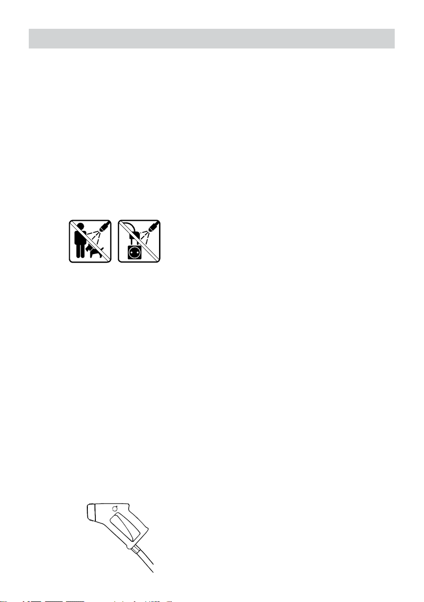
2. Water jets should never be directed towards
people, pets, electrical wiring or the Nilfi skALTO CONTRACTOR DIESEL machine itself.
3. Always switch off engine during work breaks.
11. The machine must not be used in surroundings with risk of fi re or explosion.
12. Exhaust from engine and burner contains
poisonous carbon monoxide gases. Avoid
inhalation of exhaust gases. Never run the
machine in a closed garage or confi ned area.
13. To prevent fi re hazards and to provide adequate ventilation, keep the engine at least
1m/3ft away from buildings and other equipment during operation.
14. Do not place fl ammable objects such as
gasoline, matches, etc., close to the machine
while it is running.
15. Allow only properly instructed personnel to
use the machine.
16. Never let children operate your CONTRACTOR DIESEL at any time.
17. Don’t use the machine if important parts of
the equipment are damaged - i.e. safety
devices, high pressure hoses, spray hand le,
cabinet.
4. Connect or disconnect the high pressure
hose ONLY when the engine is stopped.
5. Use only those hoses and nozzles specifi ed
by Nilfi sk-ALTO.
6. The machine should only run for a maximum
of fi ve minutes once the spray handle has
been released (the pump then circulates the
water internally and the machine will over heat unless stopped after 5 minutes).
7. The pump is equipped with a high pressure
relief safety valve. This adjustment, like any
others that require the use of tools, should
only be made by a trained service technician.
8. Operating the machine when it, or any attachments are frozen, is dangerous. Be sure
everything is thawed before operating the
machine.
9. Manufacturer’s instructions for the use of any
detergents should be carefully observed at
all times.
10. During work breaks, or any time lances or
accessories are changed, the spray handle
must be secured by rotating the safety knob
into position O.
1.1 Warning
Refi lling with diesel:
Always stop the Ruggerini engine and allow it to
cool off for at least two minutes before fi lling with
diesel. Avoid spilling diesel. If diesel nevertheless
is spilled while refi lling, the engine must not be
started before the spilled diesel has been removed. If the machine is located in a trailer, any
diesel spillage must be removed before restarting
the machine. Never use an open fl ame near the
machine. It is forbidden to smoke while refi lling
with diesel. Read the in struc tion manual for the
Ruggerini engine carefully.
NOTE: Never run the machine in a closed room.
The exhaust gases are dangerous
1.2 Asbestos
To avoid release of asbestos fi bers into the environment, Nilfi sk-ALTO strongly recommends that
this machine not be used for cleaning of materials or surfaces of materials containing asbestos.
If this machine is to be used for asbestos removal
do so only in complete compliance with approved
goverment guide li nes and/or procedures.
38
Page 4

2.0 Motor Protection De vice
The diesel engine is equipped with a protection
device called ”Oil Alert”, which stops the engine
if the oil level is insuffi cient. If this occurs, check
the engine for leaks, and after making sure the
machine is level, refi ll it to the proper level. The
engine can then be restarted.
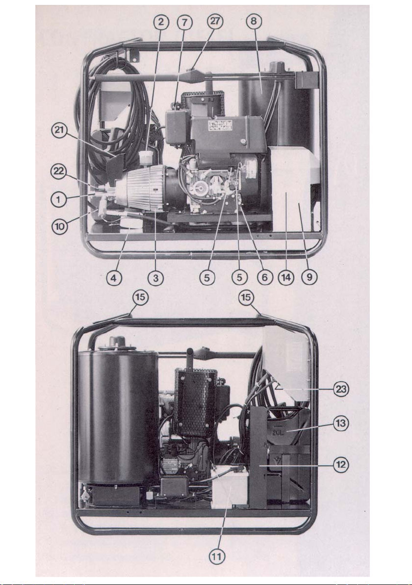
3.0 Key photo’s EN
(See drawing on the cover)
1. Water inlet and fi lter
(quick-coupler for supply hose)
2. Pump oil level inspection and fi ll cup
3. Oil drain plug for pump
4. Sludge container
5. Engine oil dipstick and fi ller tube
6. Oil drain plug for diesel engine
7. Diesel fi lling cap
8. Burner coil
9. Fan for burner
10. High pressure outlet (male quick-connector)
11. Battery
12. Container rack for detergents
13. ”Jerry-can” for heating oil
14. Burner fuel fi lter
15. Frame lift points
16. Thermostat
17. Thermometer
18. Key for electric start
19. Battery charge control
20. »Oil Alert« (see section 2.0)
21. Pressure gauge
22. Knob for adjustment of water volume
23. Fuse (protection of electronic unit)
rating 1.25 AT
Double spray lance with hose
24. High pressure, steam-capable hose
25. Male connector
26. Quick coupler
27. Pressure adjustment
28. Release trigger
29. Standard double spray lance
30. Low pressure nozzle
31. High pressure nozzle
32. Spray handle
33. Trigger safety knob
35. Data plate
36. Inlet hose w. fi lter
39
Page 5

4.0 Application EN 6.0 Accessories EN
Nilfi sk-ALTO’s diesel powered high pressure
washers can be used for all outdoor cleaning
jobs for which steam, hot or cold water is used.
Detergents can be used (see section 8.5)
4.1 Handling and Transport
When handling the machine with a fork lift truck,
be sure the forks extend completely under the
machine to prevent tipping. When lifting the
machine, a sling may be wrapped around the
upper frame tubes for lifting. Ensure that personnel aren’t under or near the machine during
lifting. When transporting the machine in a truck
or trailer, be sure that it is secured against sliding
or tipping.
In order that you may make the most of your high
pressure washer, Nilfi sk-ALTO has produced a
very comprehensive accessory program, including a pneumatic tire kit especially for the CONTRACTOR DIESEL.
Please feel free to contact your Nilfi sk-ALTO supplier for further information.
5.0 Standard equipment
The mac hi ne is delivered with a dou ble lance
and a spray handle with high pres su re steamcapable hose. The low pressure tube (pos. 30)
is fi tted with a fl at jet nozzle 6530* and the high
pres su re tube (pos. 31) with a fl at jet nozzle
1506*.
*) The fi rst two digits of the nozzle number refer
to the spray angle, in degrees. The last two digits
indicate the water fl ow in l/min. at a pres su re of
20 bar and a temperature of 20°C.
The actual nozzle orifi ce size are 0.63” (1.6 mm)
for the nozzle 1506 and 0.142” (3.6 mm) for the
nozzle 6530. NEVER replace the nozzles with
those of a smaller size.
Maximum working pressure and temperature
rating are embossed on the Nilfi sk-ALTO hose.
Use only Nilfi sk-ALTO high pressure, steamcapable hoses. In case of damage to your hose,
DO NOT attempt to repair the hose yourself! The
thrust (backwards turned force) on the nozzle is
approximately 12.5 ft/Ib (55 N).
Since the nozzles are mounted at an angle to the
lance, there will be a torque effect at the handle
when spraying. Always use two hands when
operating the spray equipment.
40
Page 6
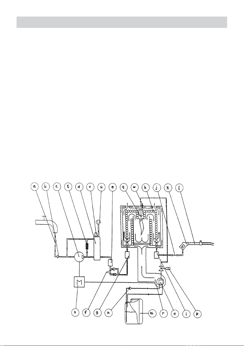
7.0 Functional description EN
The water passes from the inlet connector (a)
through a water fi lter (b) and into the high pres su re pump (c). The high pressure water is passed through the regulating unloader (recycling
valve) (d) and the fi rst fl ow control (e) to the
throttle valve (f) and through the second fl ow
control (g) into the burner-coil (h). Here the water
is heated to the required tem pe ra tu re. At the
outlet of the burner-coil the hot high pres su re
water passes the tem pe ra tu re sensor (i) and
proceeds through the outlet connector (j) to the
spray handle (k) and double spray lance (1.) The
fuel is drawn from the fuel tank (m) through the
fuel fi lter (n) by the fuel pump (a). The fuel pump
passes the fuel through the magnetic solenoid
valve (p) to the fuel nozzle (q) where it is ignited.
The combustion in the burner is monitored by
the fl ame sensor (w) and is supplied with air from
the fan (r), which together with the high pres su re
pump (c) are driven by the diesel engine (s).
a Inlet quick-connector
b Water fi lter
c High pressure pump
d Unloader/regulator (recycling valve)
e Flow switch
f Throttle valve
g Flow switch
h Burner coil
i Temperature sensor
j Outlet quick-connector
k Spray handle
I Double spray lance
m Fuel tank ”Jerry-can”
n Burner fuel fi lter
o Fuel pump
p Magnetic solenoid valve
q Fuel nozzle
r Blower for burner
s Diesel engine
t Safety valve (internal)
u Pressure gauge
v Water volume adjustment
w Flame sensor
41
Page 7

Functional description EN
7.1 High pressure pump
An unloader (recycling valve) and a safety valve
are located on the pres su re side of the high pressure pump. The unloader recirculates the water
to the suction side of the pump when the spray
handle is closed or if a nozzle is bloc ked. The safety valve is adjusted to approx. 25 bar (360 psi)
above the working pressure. The high pressure
pump should not run idle for more than 5 min.,
since the water inside the pump gets hot while it
is recirculating. The unloader ens ures there is no
pressure in the pump when the engine is stopped. The unloader and safety valve are adjusted
and sealed at the factory. DO NOT attempt to
change this adjustment.
7.2 Burner system
The burner is controlled by electronic circuits
which include a thermostat, fl ow switches to
evaluate water fl ow and a sensor to monitor the
fl ame. Water temperature is regulated by the
thermostat. Flow switches ensure there is water
fl owing through the machine before allowing the
burner to light. These devices are connected to a
printed circuit board which activates a magnetic
solenoid valve on the fuel pump to supply or stop
fuel fl ow to the burner. There are two fl ow switches installed, for additional safety and protection of the burner coil. The circuit board ensures
that they agree before allowing fuel to fl ow to the
burner. The fl ame sensor is a separate circuit
which stops the machine if there is no fl ame in
the burner in hot water or steam mode.
It is important for the life of the fuel pump, that
the machine is not allowed to run in the hot water
or cold water mode, with empty fuel tank. If the
burner stops working unexpectedly, check the
fuel level in the tank and refi ll it if necessary.
7.4 Spray lance
The double spray lance is fi tted with 2 nozzles, a
high pressure nozzle and a low pressure nozzle.
When the pressure adjustment valve (pos. 27) is
completely closed only the high pressure nozzle
is used. Both the high pres su re nozzle and the
low pressure nozzle are used when the pressure
adjustment valve is opened. Nozzles with smaller
orifi ce size (0) than described in section 5.0 must
not be mounted on the lance.
7.3 Diesel engine
A description and operating/maintenance instructions for the Ruggerini engine will be found
in the Ruggerini manual provided with the CONTRACTOR DIESEL. Please read this before
starting up. The throttle limit of the engine has
been adjusted by Nilfi sk-ALTO, so that the max.
number of revolutions corresponds to the max.
pressure of the pump. The adjustment is sealed.
This adjustment must not be changed.
42
Page 8

8.0 Connections EN
8.1 High pressure Hose
Connect the high pressure, steam-capable hose
(pos. 24), to the outlet quick-coupling (pos. 10)
on the machine front. Use only original Nilfi skALTO high pressure, steam-capable hoses. The
hose should not be exposed to abuse, such as
knots, kinks, contact with sharp objects or external heat sources, as this may cause bur sting.
Only Nilfi sk-ALTO high pressure, steam-capable
hose should be used for extension hoses. The
extension hoses should not exceed a total maximum length of 300 ft (100 m).
8.2 Spray handle and lance
Check the male connector (pos. 25) of the spray
lance for foreign material. With one hand, grasp
the quick coupler fi tting (pos. 26) and pull it
forward. Insert the male connector of the lance
or accessory into the spray handle quick-coupler,
and release the fi tting. Pull the lance or accessory forward to ensure it is correctly and tightly
installed, before operating the machine. NEVER
release a lance or accessory while water or
steam are coming from the nozzles of the lance
or accessory.
8.3 Water connection
The water inlet connection is at the front of the
machine, on the pump (pos. 1). Before connecting the water supply hose, it should be fl ushed
to remove any impurities. The machine can be
connected directly to a pressurized water supply
or a tank. The inlet pressure must not exceed 15
bar (218 psi) and the water tem pe ra tu re must
not exceed 35°C (95F°) . When the mac hi ne
is connected to a water supply with back-fl owpreventer the water supply hose must be at least
6 m (20 ft) in length. If there are impurities in the
water source, it is advisable to provide additional
fi ltration in the inlet line. Ask your Nilfi sk-ALTO
representative about the fi lters and fi lters available for your CONTRACTOR.
8.4 Suction Mode
The machine is self priming, when used from a
tank or stream, etc. The inlet hose must be fi lled
with water before starting up. The self priming
height depends on the water temperature. Max.
self priming height of 5 m (17 ft) is reached with
cold water (up to 8°C/47°F). Foreign material
in the water supply can damage your machine.
If there is a risk of foreign material in the water
source entering the supply hose, a fi lter or fi lter
must be mounted.
8.5 Use of Detergents
The machine is supplied as standard without
detergent injection equipment. In self priming
mode, detergents must not be added to the feed
water (pos. 1), and thereby circulated through the
pump. If your work requires detergents, they may
be added through the optional external (downstream) injector available from your Nilfi sk-ALTO
supplier.
NOTE! Certain organic solvents are aggressive
to rubber and plastics used in high pressure
hoses and must therefore not be used. Using
detergents outside the range from 4.0 - 10.0 pH,
will result in a loss of working life for your high
pressure hose and seals in the spray handle,
lances and other accessory. Follow precisely the
directions printed on the packing when using
detergents.
8.6 Fuel for burner
Use ONLY ”heating oil”, kerosene or diesel fuel
in the ”Jerry-can” fuel tank for the burner. DO
NOT put gasoline in the burner fuel can!
8.7 Fuel for engine
Use only clean auto-diesel for the Ruggerini
engine.
43
Page 9

9.0 Operating instructions EN
9.1 Start-up procedure
1. Check that the pump oil level is between the
MIN. and MAX. marks (pos. 2). Oil type: Nilfi skALTO Pump Oil 100.
2. Check the oil level on the Ruggerini engine.
Oil type: Choose oil type in accordance with
the instructions in the Ruggerini manual.
3. Run water through the inlet hose before con-
necting in order to remove possible impurities
in the hose. Any water supply valve must be
fully open in order to provide suf fi cient water
supply.
4. Open the small venting cap on the ”Jerry-can”
if you intend to operate in hot water or steam
mode.
5. Turn the thermostat (pos. 16) to the blue fi eld.
6. Start the Ruggerini engine as described in the
enclosed operating instructions. The key for
the electric start has the following 3 positions:
1 ”0” off
2 ”I” run
3 the startkey will return to position 2
when released.
7. Turn the trigger safety knob (pos. 33) to po-
sition 0 and squeeze the trigger of the spray
handle (pos. 28) allowing water to fl ow until
the stream is steady.
8. When the engine is warmed up, check that
max. working pressure does NOT exceed the
maximum allowable pump pressure. This can
be taken from the pressure gauge and must
not exceed 180 bar (2600 psi). Over load will
reduce the life of the machine. (See section
14.0).
9.2 Cold water operation
After the starting up procedure the machine is
ready for cleaning with cold water.
d) Start the machine, if stopped, and activate the
spray handle to start the burner.
IMPORTANT: For safety reasons it is important
that instruction (a), above, always be followed!
Note: If the engine stops immediately after
having been started up, it should be checked
whether the throttle control is set at idle speed.
If it is, the throttle control should be adjusted to
full speed.
9.4 Adjustment of pressure and
water volume
High pressure/volume
In order to achieve maximum working pressure the
pressure adjustment knob (pos. 27) on the lance
should be turned all the way in (clockwise until
completely closed) and the volume adjustment
knob (pos. 22) situated on the front of the pump
should be turned all the way out (counterclockwise). The water volume is infi nitely variable up
to the max. capacity of the machine.
Low pressure/volume
To reduce the working pressure, turn the pres su re adjustment knob (pos. 27) on the lance,
counterclockwise until the desired result is achieved. To reduce the water pressure AND volume,
release the trigger (pos. 28) or stop the machine.
Turn the volume adjustment knob on the front
of the pump, clockwise, reducing water fl ow and
volume. Test the results, and repeat the process
until you have achieved the results you wish. By
varying the settings of the pres su re adjustment
knob on the lance, and the volume adjustment
knob on the pump, you may obtain pressures
from 4 bar (60 psi) to 180 bar (2600 psi), and
water fl ows from 6 l/min. (1.6 US gpm) to 20.5
l/min. (5.4 US gpm).
9.3 Hot water/Steam operation
Hot water:
Adjust the thermostat (pos. 16) to the required
temperature, 30-95°C (86-200°F).
Steam:
a) Adjust to temperatures above 95°C (200°F)
ONLY with the trigger on spray handle
released.
b) Turn the water volume adjustment knob (pos.
22) completely in (fully clockwise).
c) Adjust the thermostat to the required tem pe -
ra tu re, 95-150°C (200-302°F).
44
9.5 Shutdown
WARNING: Danger of burn
Do not disconnect the high pressure hose until
you have completed the following steps (risk of
injury):
1. Turn the thermostat (pos. 16) to the blue fi eld.
Spray cold water until the water tem pe ra tu re is
under 50°C (122°F). Disconnect or turn off the
water supply.
2. Squeeze the trigger of the spray handle for a
short time to empty the system of water.
3. Stop the diesel engine. (See instructions for
the Ruggerini engine).
4. Disconnect the high pressure hose.
Page 10

10.0 Storage/frost proofi ng
It is advisable to store the machine in a frost
proof place between operations. If this is not
possible the machine should be protected in the
following way:
1. Disconnect the inlet hose. Remove the lance
(pos. 29) and empty it of water.
2. Ensure that the thermostat is set in the blue
fi eld, and start the machine, allowing it to run
with the spray handle opened until it is empty
of water.
3. Place a suction hose in a bucket with 6-8 l
(1.5-2 gallons) anti-freeze.
4. Place the spray handle (without spray lance)
above the bucket, open the spray handle so
that the antifreeze can circulate. Open and
close the spray handle a few times.
5. Rem ove the suction hose from the bucket and
allow the machine to pump all of the solution
back into the anti-freeze container. The antifreeze can be re-used, but keep in mind that
it is slightly diluted with water each time this
is done.
Important:
To avoid damage always ensure that the washer,
the hoses and the spray lance are unfrozen
before restarting. Place the washer and the accessories in a warm environment for some time
before starting up.
11.0 Model tag
This machine has the model name, ”CONTRACTOR DIESEL”. The model de sig na ti on is printed
on a decal positioned on the control panel and
on the data plate. The data plate provides the
following important information:
1. Model designation
2. Production code (year and week) 3. Serial
number
4. Pump pressure
5. Water volume
6. Max pressure
7. Max temperature
8. Manufacturer
45
Page 11

12.0 Maintenance EN
12.1 Water inlet fi lter
The inlet water connection (pos. 1) contains
a fi lter to prevent impurities entering the highpressure pump. This fi lter must be inspected at
regular intervals, and cleaned as required. The
fi lter can be removed after removing the quick
coupling.
NOTE:
To avoid serious damage to the rubber gasket,
the quick coupling should be tightened only
gently.
12.2 Couplings/connectors
To prevent leakage and damage to connectors/
couplings on hoses, spray handle, machine and
spray lance, these need to be cleaned occasionally and lightly lubricated with oil or grease.
12.3 Oil Change
The oil level must be checked at regular intervals
(see section 9.1). The oil should be changed according to the following guidelines:
1. OIL CHANGE FOR PUMP
Change the oil after 1000 hours of operation, or
when the oil appears ”milk-white”. Take off the
cover of the oil glass (pos. 2). Unscrew the oil
drain plug on the bottom of the pump (pos. 3).
Drain the oil and then clean the dirt off the drain
plug. Screw the plug in and top up the pump with
fresh oil through the oil glass.
The pump holds approximately 1 quart (1 litre)
of zincless hydraulic oil. From Nilfi sk-ALTO the
pump is fi lled with Nilfi sk-ALTO Pump Oil 100.
When refi lling and changing the oil this or a
substitute with the following specifi cations may
be used:
Zincless Hydraulic Oil
ISO no. 100
Viscosity Index (VI) min. 130
Pour Point below -30°C
SLUDGE CONTAINER
It is normal for a small amount of oil and water
to get past their seals. This oil/ water is collected
in a sludge container (pos. 4). Empty the container before it has fi lled completely. This oil/water
mixture must not be re-used in the pump.
2. ENGINE OIL CHANGE
Refer to the Ruggerini engine manual for breakin and normal operating oil change requirements.
Carry out fi rst oil change after i0 hours of operation and then every 100 hours. Not less than
once every six months, however.
NOTE: Protect the environment by properly
disposing of used pump and engine oil.
12.4 Burner fuel fi lter
To prevent foreign material from entering the fuel
pump a fi lter (14) is fi tted between the fuel tank
and the fuel pump. This fi lter must be changed
regularly, the frequency depends on the purity
of the fuel. Replacement of the fi lter each year is
recommended. See also diagnosis of faults and
repair 16.0.
12.5 Descaling
After a period of operation depending on the
hardness of the water, scale deposits will begin
to accumulate in the heating coil. These deposits
will reduce the effect of the water heating system
and increase the fuel consumption. The machine
should therefore be descaled regularly. If the
machine adjusted on maximum water volume will
not heat cold water (8°C/47°F) to 70°C (158°F)
within three minutes, the burner or coil require
servicing or descaling, as follows:
NOTE:
Always carry out the descaling according to the
instructions supplied with the descaling product:
1. Disconnect the high pressure hose
2. Place an inlet hose in a container of at least
10 l (3 gallon) capacity, with a solution of
recognized descaling product (i.e. Nilfi sk-ALTO
STONEX), and water in the recommended
percentage (not normally over 10% of the
descaling product ratio 1:10). Ask your Nilfi skALTO distributor for recommendations.
3. Start the machine.
4. Switch off the machine when the water from
the outlet fi tting is colored by the scale rem over.
WARNING! The solution can be caustic. Note:
Air must in no circumstances get into the sy stem;
therefore the container with scale rem over must
never be emptied completely.
46
Page 12

Maintenance EN 13.0 Warranty EN
5. Leave the machine for 20 minutes.
6. Start the machine and pump the used so lu ti on
into a container for proper disposal.
7. Immediately connect a fresh water supply and
turn it on.
8. Start the machine, let it work for 5-10 minutes,
until all the scale remover is out of the sy stem.
9. If necessary, repeat the procedure from instructions 2 to 8.
12.6 High pressure nozzle care
An obstructed nozzle causes an increase in
pump pressure. Immediate correction is required.
1. Stop the machine and dismount the spray
lance.
2. Clear the nozzle obstruction with a Nilfi skALTO nozzle tool No. 6401654.
WARNING: This operation must be per-formed
ONLY with the lance removed from the mac hi ne.
3. Backfl ush the spray lance with water. Use the
spray handle, pressing it towards the nozzle
protection cap on the front of the spray lance.
4. If the pressure is still too high, repeat items
1-3, or remove the nozzle from the lance for
cleaning.
Nilfi sk-ALTO warrants against defects in the supplied product for a period of 12 months from the
purchase date subject to the following con dit ions:
- that defects are attributable to material or
ma nu fac tu ring fl aws. (Items which require replacement due to normal wear and tear, abuse
or misuse are not included in this limited warranty).
- Repairs required due to improperly performed
service or repairs, are excluded.
- Repairs required due to the use of non-Nilfi skALTO parts or accessories, are excluded.
- Repairs required by operation of the machine
in a manner not prescribed in this Instruction
Manual.
The engine warranty is as described by, and in
accordance with the practices and policies of
Ruggerini Motor Company. See the Ruggerini
documents for details.
47
Page 13

14.0 Troubleshooting EN
Fault Cause Repair
The engine fails to start Insuffi cient diesel supply Refi ll diesel tank.
Battery run down Recharge the battery*)
Fuse blown Exchange fuse. See section 3.0.
The pump is frozen Let the pump thaw.
Working pressure too high Nozzle partly blocked Clean the nozzle. See section 12.6.
Working pressure Valve for regulation of Open fully the valve for regulation of
too low water volume is not water.
adjusted to max pressure Turn counterclockwise.
Nozzle worn Replace nozzle.
Motor speed too low Contact Nilfi sk-ALTO service technician.
Irregular working Air in the pump Repeat the venting procedure.
pressure Inlet fi lter/fi lter blocked Clean the fi lter. See section 12.1.
Insuffi cient water supply Change to a water supply with greater
from the water works output. If this is not possible; turn the
valve for regulation of the water volume
clockwise, until the machine works smoothly.
In suction mode: Excessive suction head Read section on suction mode (8.4).
or excessively hot water
Nozzle partly blocked Clean nozzle. See section 12.6.
No working pressure Nozzle blocked Clean nozzle. See section 12.6.
No water Check the water connection.
Unloader (recycling valve) Allow the machine to thaw.
frozen See section 10.0.
High pressure hose/ Allow the high pressure hose/
spray lance frozen spray lance to thaw.
The burner does not Insuffi cient fuel supply Refuel.
ignite Fuel fi lter blocked Clean the fi lter. See section 12.4
Should faults occur other than those mentioned above, please contact the nearest Nilfi sk-ALTO service
organization *) IMPORTANT NOTE: To avoid damage to the electronic systems, the battery connecting
cables must be removed when recharging the battery.
15.0 Technical data EN
Model CONTRACTOR DIESEL
Pump pressure, max. bar/psi 180/2610
Water volume at min/max pressure l/min-USgpm 20,5/19 - 5.42/5
Max. temperature of inlet water °C/°F 35/95
Heating power kW/Kcal 115/98.200
Nozzle, spray angle degrees (05) 15/65
Self-priming, max. lift m/ft 5/16.5
Engine Ruggerini MD 151
Rated effect kW/hp 12/16.3
Start system Electric start
Battery V/Ah 12/50
Diesel consumption, max. pressure l/h-USgph 3.0-0.79
Fuel consumption at 60°C/140°F 1) l/h-USgph 7.5-1.98
“Jerry-can”, capacity l/Usg 20/5
Sound power level (LWA) of the machine measured in accordance with ISO 3746: 112 dB(A).
Sound pressure level (L
1
) Delta t= 52°C/126°F
This machine has been manufactured in accordance with the EMC directive 89/336/EEC inclusive of subsequent
amendments.
Specifi cations are subject to alterations.
48
) measured in accordance with ISO 11202 [DISTANCE 1m] [FULL LOAD]: 100 dB(A).
PA
Page 14

Page 15
Page 16

http://www.nilfi sk-alto.com
HEAD QUARTER
DENMARK
Nilfi sk-Advance Group
Sognevej 25
DK-2605 Brøndby
Tel.: (+45) 4323 8100
Fax: (+45) 4343 7700
E-mail: mail.com@nilfi sk-advance.com
SALES COMPANIES
ARGENTINA
Nilfi sk-Advance srl.
Edifi cio Central Park
Herrera 1855, Offi ce 604
Ciudad Autónoma de Buenos Aires
Tel.: (+54) 11 6091 1571
Fax:(+54) 11 6091 1575
AUSTRALIA
Nilfi sk-ALTO
48 Egerton St.
P.O. Box 6046
Silverwater, N.S.W. 2128
Tel.: +61 2 8748 5966
Fax: +61 2 8748 5960
E-mail: info@nilfi skalto.com.au
AUSTRIA
Nilfi sk-Advance GmbH
Metzgerstrasse 68
5101 Bergheim bei Salzburg
Tel.: 0662 456 400-0
Fax: 0662 456 400-34
E-mail: info.at@nilfi sk-advance.com
BELGIUM
Nilfi sk-ALTO a division of Nilfi sk-Advance n.v-s.a.
Riverside Business Park
Boulevard Internationalelaan 55
Bâtiment C3/C4 Gebouw
Bruxelles 1070 Brussel
Tel.: (+32) 2 467 60 40
Fax: (+32) 02 466 61 50
E-mail: info.be@nilfi sk-alto.com
CANADA
Clarke Canada
Part of the Nilfi sk-Advance Group
4080-B Sladeview Crescent, Unit 1
Mississauga, Ontario L5L 5Y5
Tel.: (+1) 905 569 0266
Fax: (+1) 905 569 8586
CHILE
Nilfi sk-Advance S.A.
San Alfonso 1462
Santiago
Tel.:(+56) 2 684 50 00
E-mail: Pablo.noriega@nilfi sk.com
CHINA
Nilfi sk-Advance (Shenzhen) Ltd.
Blok 3, Unit 130 1001 Honghua Road
Int. Commercial & Trade Center
Fuitian Free Trade Zone
518038 Shenzhen
Tel.: (+86) 755 8359 7937
Fax: (+86) 755 8359 1063
CZECH REPUBLIC
ALTO Ceská Republika s.r.o.
Do Čertous 2658/1
193 00 Praha 9
Tel.: (+420) 24 14 08 419
Fax: (+420) 24 14 08 439
E-mail: info@alto-cz.com
DENMARK
Nilfi sk-Advance A/S
Industrivej 1
9560 Hadsund
Tel.: +45 7218 2100
Fax: +45 7218 2105
E-mail: salg.dk@nilfi sk-alto.com
Nilfi sk-ALTO Food division
Division of Nilfi sk-Advance A/S
Blytækkervej 2
9000 Aalborg
Tel.: +45 7218 2100
Fax: +45 7218 2099
E-mail: food.division@nilfi sk-alto.dk
6229950 a (01.2009)
FINLAND
Nilfi sk-Advance Oy Ab
Piispantilankuja 4
02240 Espoo
Tel.: +358 207 890 600
Fax: +358 207 890 601
E-mail: asiakaspalvelu.fi @nilfi sk.com
FRANCE
Nilfi sk-ALTO
ALTO France SAS
Aéroparc 1
19 rue Icare
67960 Entzheim
Tel.: (+33) 3 88 28 84 00
Fax: (+33) 3 88 30 05 00
E-mail: info.fr@nilfi sk-alto.com
GERMANY
Nilfi sk-ALTO
Division of Nilfi sk Advance
Guido-Oberdorfer-Str. 10
89287 Bellenberg
Tel.: (+49) (0) 180 5 37 37 37
E-mail: info.de@nilfi sk-alto.com
GREECE
Nilfi sk-Advance SA
8, Thoukididou str.
164 52 Argiroupolis
Tel.: +30 210 96 33443
Fax: +30 210 96 52187
E-mail: nilfi sk-advance@clean.gr
HOLLAND
Nilfi sk-ALTO
Division of Nilfi sk-Advance BV
Camerastraat 9
3322 BB Almere
Tel.: (+31) 36 5460 760
Fax: (+31) 36 5460 761
E-mail: info.nl@nilfi sk-alto.com
HONG KONG
Nilfi sk-Advance Ltd.
2001 HK Worsted Mills Ind’l Bldg.
31-39 Wo Tong Tsui St.
Kwai Chung
Tel.: (+852) 2427 5951
Fax: (+852) 2487 5828
HUNGARY
Nilfi sk-Advance Kereskedelmi Kft.
II. Rákóczi Ferenc út 10
2310 Szigetszentmiklos-Lakihegy
Tel: (+36) 24475 550
Fax: (+36) 24475 551
E-mail: info@nilfi sk-advance.hu
INDIA
Nilfi sk-Advance India Limited
349, Business Point,
No 201,2nd fl oor, above Popular Car World,
Western Express Highway, Andheri ( East),
Mumbai - 400 069
Tel: (+91) 22 321 74592
ITALY
Nilfi sk-ALTO
Divisione di Nilfi sk-Advance A/S
Località Novella Terza
26862 Guardamiglio (LO)
E-mail: d.puglia@nilfi sk-advance.it
JAPAN
Nilfi sk-Advance Inc.
1-6-6 Kita-shinyokohama, Kouhoku-ku
Yokohama, 223-0059
Tel.: (+81) 45 548 2571
Fax: (+81) 45 548 2541
MALAYSIA
Nillfi sk-Advance Sdn Bhd
Sd 14, Jalan KIP 11
Taman Perindustrian KIP
Sri Damansara
52200 Kuala Lumpur
Tel.: (+60) 3 603 6275 3120
Fax: (+60) 3 603 6274 6318
MEXICO
Nilfi sk-Advance de Mexico, S. de R.L. de C.V.
Prol. Paseo de la Reforma 61, 6-A2
Col. Paseo de las Lomas
01330 Mexico, D.F.
Tel: +52 55 2591 1002 (switchboard)
Fax: +52 55 2591 1002 ext. 229
E-mail: info@advance-mx.com
NORWAY
Nilfi sk-Advance AS
Bjørnerudveien 24
1266 Oslo
Tel.: (+47) 22 75 17 70
Fax: (+47) 22 75 17 71
E-mail: info.no@nilfi sk-alto.com
POLAND
Nilfi sk-Advance Sp. Z.O.O.
05-800 Pruszków
ul. 3-go MAJA 8
Tel.: +48 22 738 37 50
Fax: +48 22 738 37 51
E-mail: info@nilfi sk-alto.pl
PORTUGAL
Nilfi sk-ALTO
Division of Nilfi sk-Advance Lda.
Sintra Business Park
Zona Industrial Da Abrunheira
Edifi cio 1, 1° A
P2710-089 Sintra
Tel.: +35 808 200 537
Fax: +35 121 911 2679
E-mail: mkt@nilfi sk-advance.es
RUSSIA
Нилфиск-Эдванс
127015 Москва
Вятская ул. 27, стр. 7
Россия
Tel.: (+7) 495 783 96 02
Fax: (+7) 495 783 96 03
E-mail: info@nilfi sk.ru
SINGAPORE
Nilfi sk-Advance Pte. Ltd.
Nilfi sk-ALTO Division
40 Loyang Drive
Singapore 508961
Tel.: (+65) 6 759 9100
Fax: (+65) 6 759 9133
E-mail: sales@nilfi sk-advance.com.sg
SPAIN
Nilfi sk-ALTO
Division of Nilfi sk-Advance S.A.
Torre D’Ara
Paseo del Rengle, 5 Pl. 10
08302 Mataró
Tel.: (+3) 4 902 200 201
Fax: (+3) 4 93 757 8020
E-mail: mkt.es@nilfi sk-alto.com
SWEDEN
ALTO Sverige AB
Member of Nilfi sk-Advance Group
Aminogatan 18, Box 4029
431 04 Mölndal
Tel.: (+46) 31 706 73 00
Fax: (+46) 31 706 73 40
E-mail: info.se@nilfi sk-alto.com
TAIWAN
Nilfi sk-Advance Taiwan Branch
No. 5, Wan Fang Road
Taipei
Tel.: (+886) 227 002 268
Fax: (+886) 227 840 843
THAILAND
Nilfi sk-Advance Co. Ltd.
89 Soi Chokechai-Ruammitr
Viphavadee-Rangsit Road
Ladyao, Jatuchak, Bangkok 10900
Tel.: (+66) 2 275 5630
Fax: (+66) 2 691 4079
TURKEY
Nilfi sk-Advance Profesional Temizlik
Ekipmanlari Tic. A/S.
Necla Cad. NI.: 48
Yenisahra / Kadiköy
Istanbul
Tel.: (+90) 216 470 08 - 60
E-mail: info.tr@nilfi sk-advance.com
UNITED KINGDOM
Nilfi sk-ALTO
Division of Nilfi sk-Advance Ltd.
Bowerbank Way
Gilwilly Industrial Estate, Penrith
Cumbria CA11 9BQ
Tel.: (+44) 1 768 86 89 95
Fax: (+44) 1 768 86 47 13
E-mail: sales.uk@nilfi sk-alto.com
USA
Nilfi sk-Advance Inc.
14600 21st Avenue North
Plymouth, MN 55447-3408
Tel.: (+1) 763 745 3500
Fax: (+1) 763 745 3718
E-mail: info@advance-us.com
VIETNAM
Nilfi sk-Advance Representative Offi ce
No. 51 Doc Ngu Str.
Ba Dinh Dist.
Hanoi
Tel.: (+84) 4 761 5642
Fax: (+84) 4 761 5643
E-mail: nilfi sk@vnn.vn
 Loading...