

Page 1

12129200. 12149200. Replacement with the new 1200W motor kit A-0.6.5.
1
ASSEMBLY INSTRUCTIONS GM 200 / 300 / 400 SERIES
Instruction No. 82129400/00-08
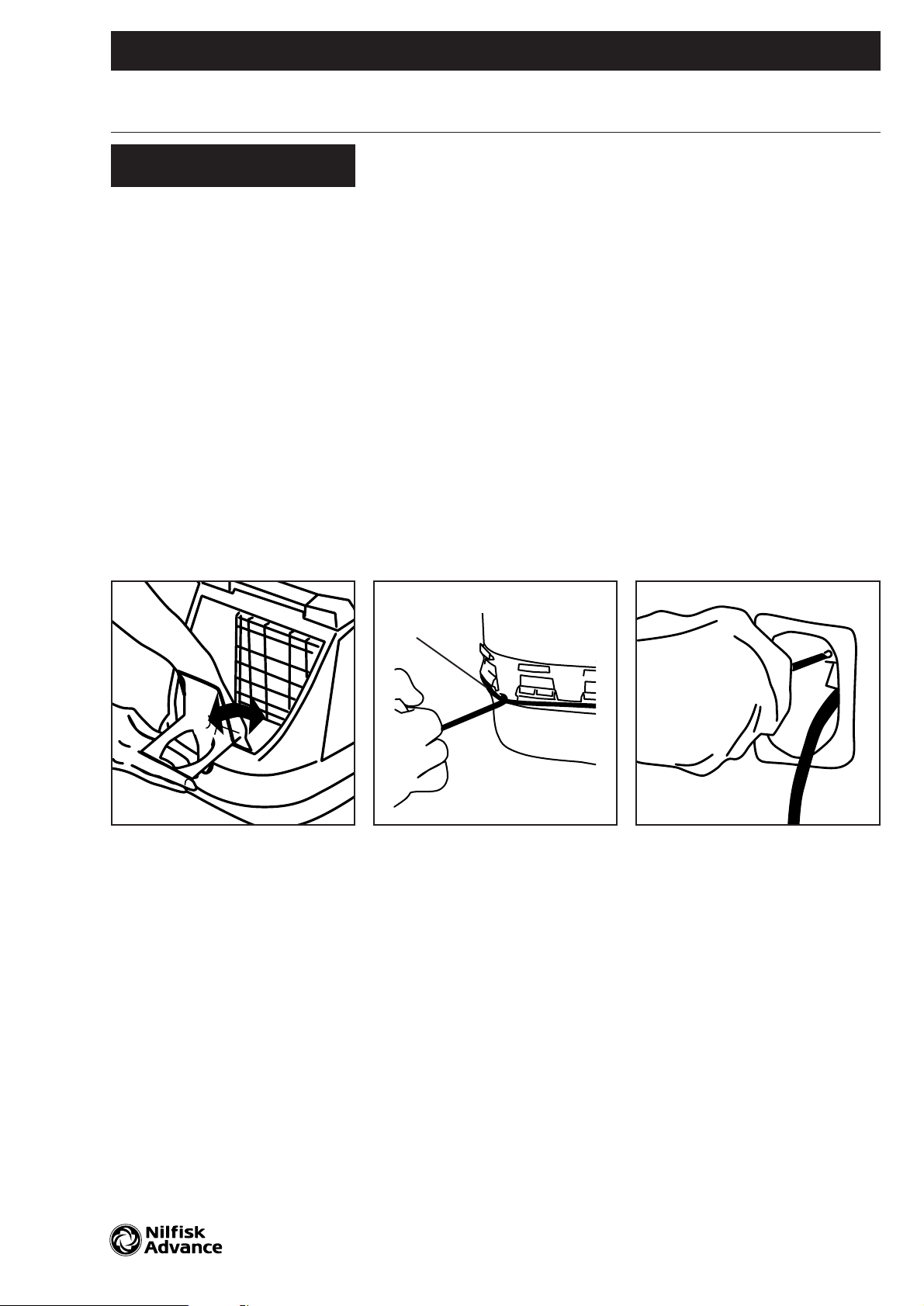
To be performed by a skilled
or instructed person only !
Disconnect the vacuum cleaner
from the power supply before
starting the work!
! Models with bag-full indicator:
Open the dust cover until it stops
and continue with a little pressure
by hand until it slides free of the
hinges.
Models with no bag-full indicator:
Open the dust cover and lift it out
of the hinges.
Remove filter with dust bag.
Remove the dust bag holder by
pressing bottom clip and ease the
holder out of the bottom. This
releases the hook at the container
wall.
@ To separate the top and bottom
housing and avoid scratches on
the parts, place tool no. 22361400
under the buffer.
Follow instruction 82361500
Remove the strap (12) by hand.
Lift up the buffer and remove the
top housing.
# Free the cord with plug from
the terminal box in the top housing
by using a Pozi screwdriver no. 2
or in old models press it out by
hand.
Remove the cord reel and lock the
cord to the reel. Remove internal
wires and release the on/off switch
by pressing a screwdriver under it.
Remove the motor housing with
four screws by a Pozi screwdriver
no. 2.
Replace the motor unit with the
new complete motor housing
included the thermal switch and
connect wires as described.
Refit in reverse order. Press the
buffer back in place by hand after
mounting the strap around the
housings.
WE
Q
12
Page 2
659643
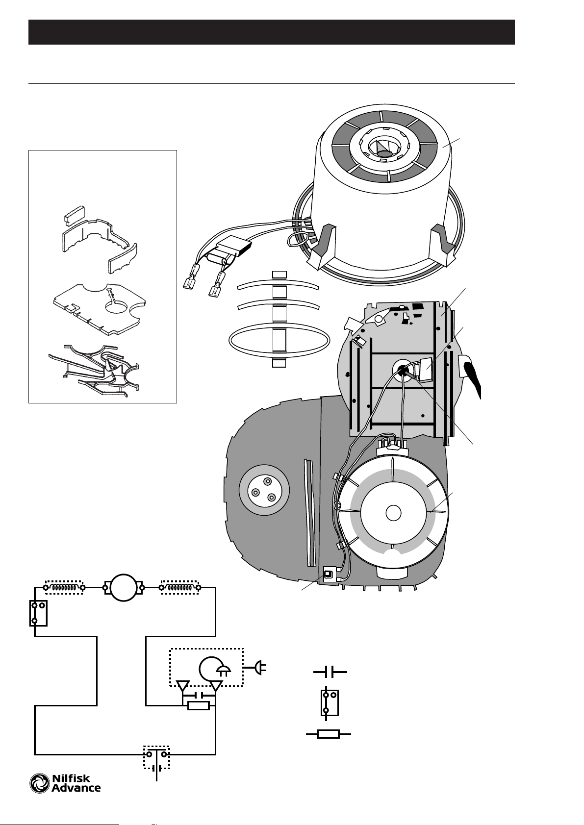
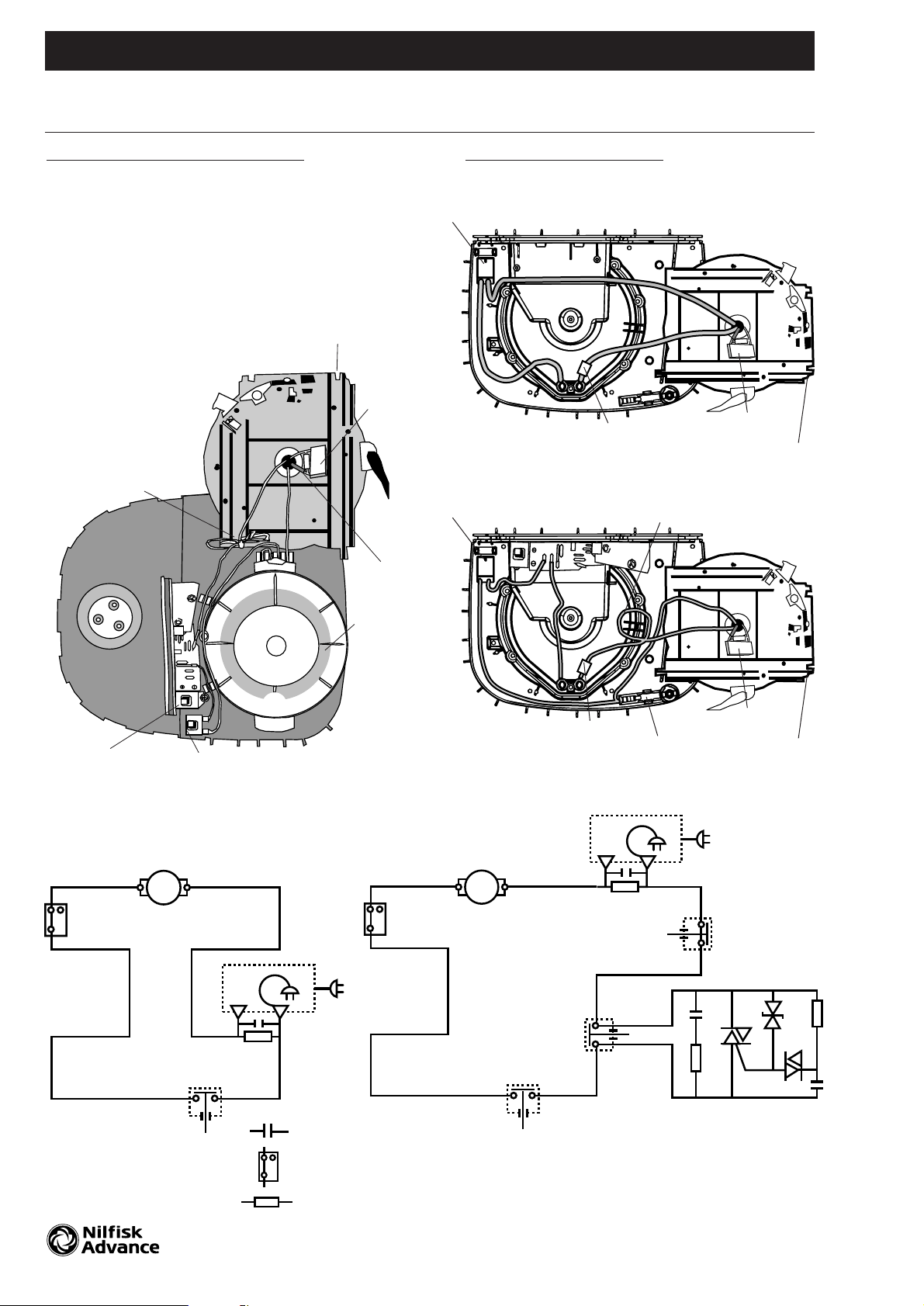
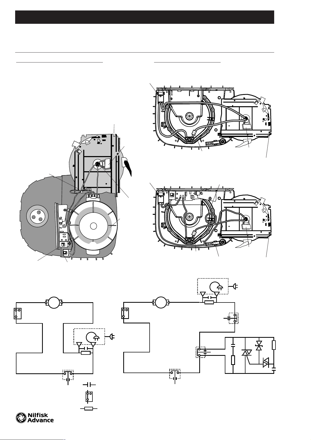
View with existing motor housing removed.
New motor
housing
to be
mounted
under existing motor
housing
Top view
New cord
reel shown
Capacitor
with foam
Flex
Existing
motor housing
Note 1
Note 1:
O-ring to be mounted only when
existing motor housing is for two
speed regulation with four grooves.
On/off switch
12129200. 12149200. Replacement with the new 1200W motor kit A-0.6.5.
2
ASSEMBLY INSTRUCTIONS GM 200 / 300 / 400 SERIES
Instruction No. 82129400/00-11
Diagram for GM 200/300/400
series with one speed
118408xx
11842200
NL
= RFI capacitor
= Thermo switch
= Resistor
Remove and scrap these when
your are installing a new motor
unit on a GM 200 / 300
81859300
81842700
81842800
81842900
81841900
Page 3
22186000. Replacement with the new 1200W motor kit A-0.6.5.
and two speed PCB 3
ASSEMBLY INSTRUCTIONS GM 200 / 300 / 400 SERIES
Instruction No. 82187100/00-08
To be performed by a skilled
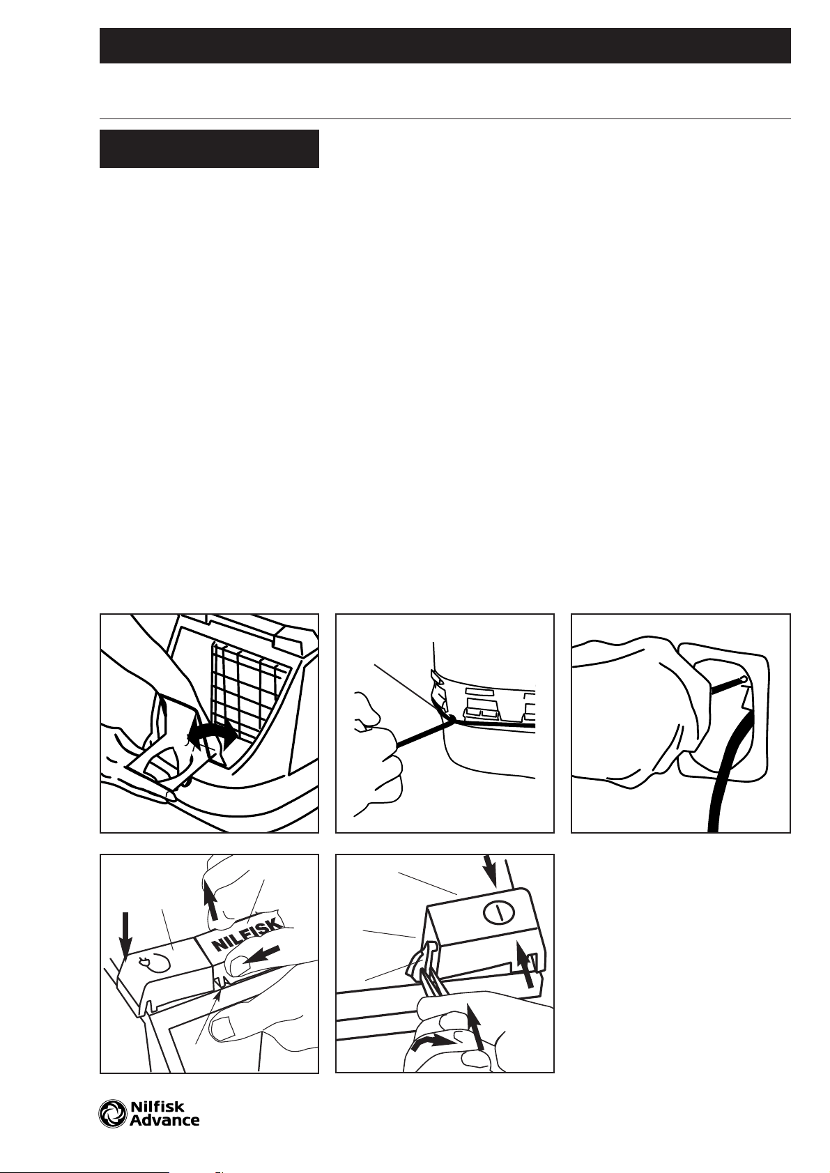
or instructed person only !
Disconnect the vacuum cleaner
from the power supply before
starting the work!
! Models with bag-full indicator:
Open the dust cover until it stops
and continue with a little pressure
by hand until it slides free of the
hinges.
Models with no bag-full indicator:
Open the dust cover and lift it out
of the hinges.
Remove filter with dust bag.
Remove the dust bag holder by
pressing bottom clip and ease the
holder out of the bottom. This
releases the hook at the container
wall.
@ To separate the top and bottom
housing and avoid scratches on
the parts, place tool no. 22361400
under the buffer.
Follow instruction 82361500
Remove the strap (12) by hand.
Lift up the buffer and remove the
top housing.
# Free the cord with plug from
the terminal box in the top housing by using a Pozi screwdriver
no. 2 or in old models press. it
out by hand.
Remove the cord reel and lock
the cord to the reel. Remove
internal wires and release the
on/off switch by pressing a
screwdriver under it.
Replace the motor unit with the
new complete motor housing
included the thermal switch and
connect wires as described.
Remove and replace the new
two-speed PCB and connect
wires.
Refit in reverse order. Press the
buffer back in place by hand
after mounting the strap around
the housings.
WE
Q
12
Page 4
659643
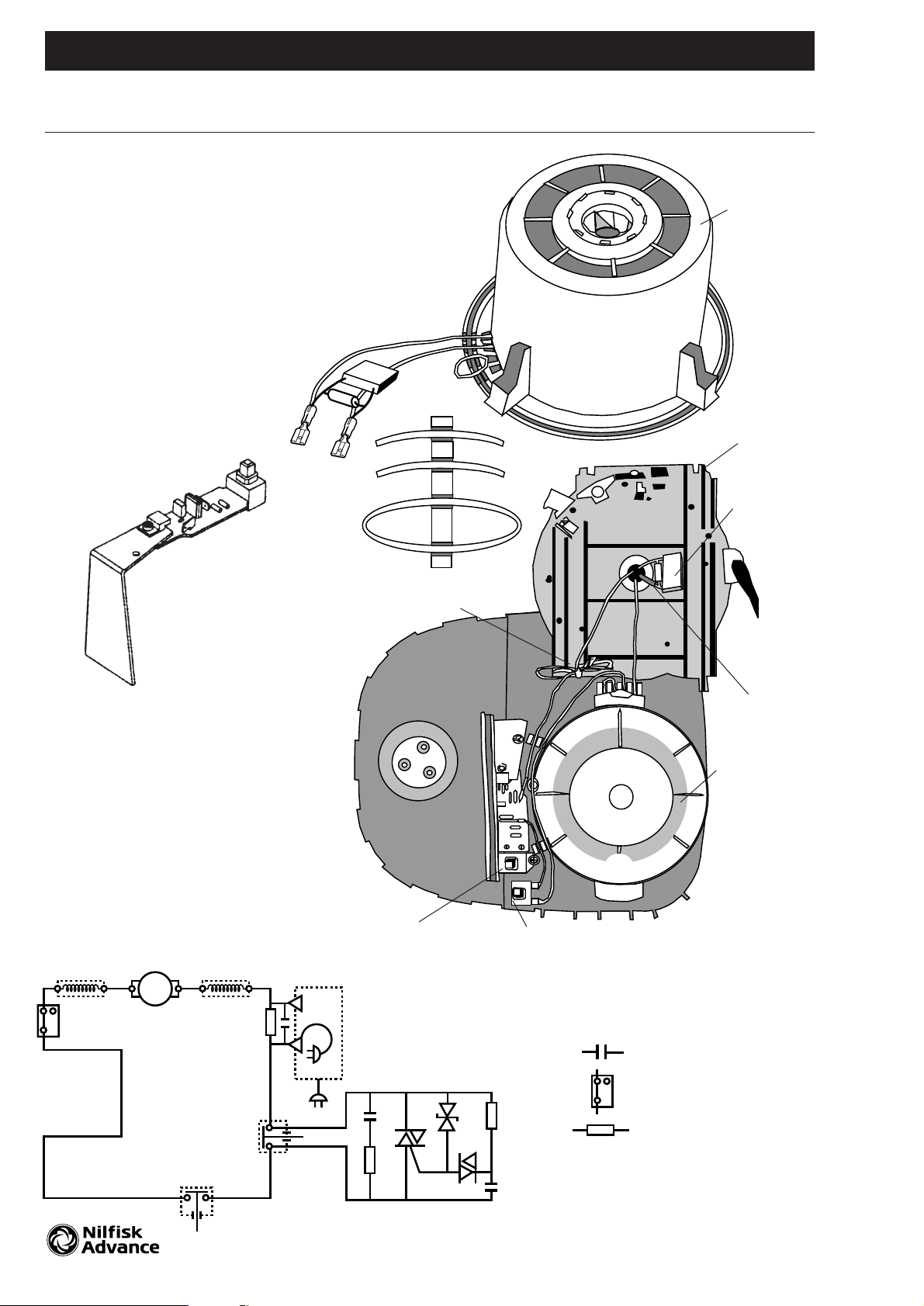
View with existing motor housing removed.
New motor
housing
to be
mounted
under existing motor
housing
Top view
New cord
reel shown
Capacitor
with foam
Flex
Existing
motor housing
Note 1
Note 1:
Internal blue wire to be turned up
and locked by a strap. (Only two
speed version).
Note 2:
O-ring to be mounted only when
existing motor housing is for two
speed regulation with four grooves.
On/off switch
Two speed switch
22186000. Replacement with the new 1200W motor kit A-0.6.5.
and two speed PCB 4
ASSEMBLY INSTRUCTIONS GM 200 / 300 / 400 SERIES
Instruction No. 82187100/00-08
= RFI capacitor
= Thermo switch
= Resistor
Diagram for GM 210, GM 320,
GM 325 and GM 330 with two
speed regulation PCB for
1200W motor
81842201
31965001
C1
R1
T1
D2
D1
R2
C2
118408 xx
Note 1
Page 5
118408XX. Replacement of the cable reel A-0.6.5.
223526XX. Replacement of the cable reel, King 500 Series 5
ASSEMBLY INSTRUCTIONS GM 200 / 300 / 400 & KING 500 SERIES
Instruction No. 82186900/00-09
To be performed by a skilled
or instructed person only !
Disconnect the vacuum cleaner
from the power supply before
starting the work!
! Models with bag-full indicator:
Open the dust cover until it stops
and continue with a little pressure
by hand until it slides free of the
hinges. Models with no bag-full
indicator: Open the dust cover and
lift it out of the hinges.
Remove filter with dust bag.
Remove the dust bag holder by
pressing bottom clip and ease the
holder out of the bottom. This
releases the hook at the container
wall.
@ To separate the top and bottom
housing and avoid scratches on
the parts, place tool no. 22361400
under the buffer.
Follow instruction 82361500
Remove the strap (12) by hand.
Lift up the buffer and remove the
top housing.
# Free the cord with plug from
the terminal box in the top
housing by using a Pozi
screwdriver no. 2 or in old
models press it out by hand.
Remove and replace the cable
reel with the internal wires.
The cable reel spring is pretightened and this should not be
changed so as to avoid damage.
Do not unwind the cable and do
not tighten the cable additionally.
Note:
Wire to be wrapped around the
post to reduce wire slack before
mounting cable reel.
It is necessary to replace the
cord reel button.
Open the accessory cover until it
stops and continue with a little
pressure by hand until it slides free
of the hinges and remove it.
$ Push down the cable release
button (a) and press by hand the
dust cover button sideways (b)
to release it, and lift it up (c).
% Release and remove the side
pivots (2) with a pair of pliers (5).
To remove the cable reel button
(3) and/or the on/off button (4),
press the two snaps on the button (d) to release it from the top
housing & lift it away after turning it 30 degrees.
Refit in reverse order.
Press the buffer back in place
by hand after mounting the strap
around the housings.
Testing the cable reel.
Draw the cable out completely
and rewind it by pressing the
button on top of the machine.
WE
Q
12
3
1
4
5
2
2
a
b
c
R
T
d
d
Page 6
659643
Top view King 500 Series
One Speed
T
op view GM 200/300/400 Series
Two Speed
Capacitor
with foam
Capacitor
with foam
New cord
reel shown
New cord
reel shown
Flex
Existing
motor housing
On/off switch
Two speed switch
118408XX. Replacement of the cable reel A-0.6.5.
223526XX. Replacement of the cable reel, King 500 Series 6
ASSEMBLY INSTRUCTIONS GM 200 / 300 / 400 & KING 500 SERIES
Instruction No. 82186900/00-09
Note 1
C1
R1
T1
D2
D1
R2
C2
Diagram for
one speed models
Diagram for
two speed models
NL
= RFI capacitor
= Thermo switch
= Resistor
Top view
Note 1:
Internal blue wire to be turned up
and locked by a strap. (Only two
speed version).
Note 2:
ONLY GM200/300/400 SERIES
O-ring to be mounted only when
existing motor housing is for two
speed regulation with four grooves.
659643
659643
On/off
Insulated terminal
Capacitor
with foam
New cord
reel shown
On/off
Insulated
terminal
On/off parking
Wrapping around post
Page 7
22147600/01. Parking clip A-0.6.5.
7
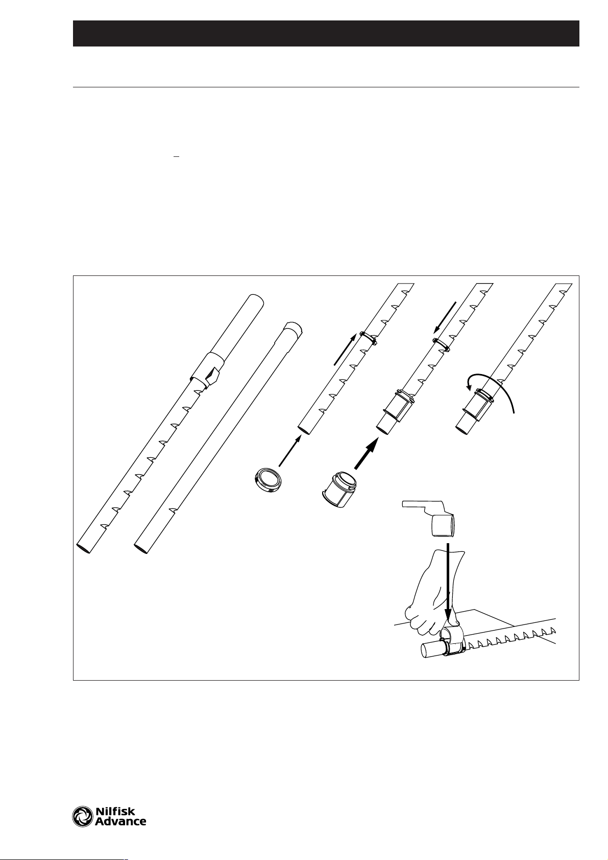
Assembling of parking clip
to the tube
➀ Mount ring on the tube.
➁ Press bush up on the straight tube until it clicks into
the groove marked 0 (the second groove on the telescopic tube). If no click during mounting on the tube,
position the bush as shown to fit to the groove.
➂ Mount the ring on the top of the brush and lock it by
turning it counterclockwise.
➃ To mount parking clip to bush, press hard by hand to
snap it into position.
ASSEMBLY INSTRUCTIONS GM 200 / 300 / 400 & KING 500 SERIES
Instruction No. 72147700/00-08
-1
0
-1
-1
0
-1
-1
0
-1
0
-1
0
-1
R
Q
W
E
Page 8
22147600/01. Parking clip A-0.6.5.
8
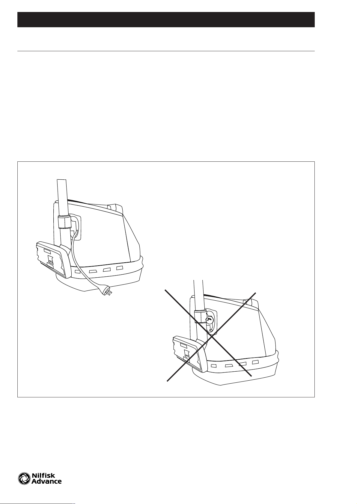
Parking of tube with nozzle
➀ Pull the plug free of the cable reel groove.
Turn nozzle to position foot-plate away from the
machine to avoid scratches on the surface and press
the parking clip-pin mounted to the tube into the hole
inside the cable reel groove.
➁ No parking, when plug is in the cable reel groove.
ASSEMBLY INSTRUCTIONS GM 200 / 300 / 400 & KING 500 SERIES
Instruction No. 72147700/00-08
!
@
Page 9
31965001. Replacement with the two speed PCB for 1200W motor. A-0.6.5.
22365700. Replacement of the on/off switch 9
22354400. Replacement of the on/off switch for parking
ASSEMBLY INSTRUCTIONS GM 200 / 300 / 400 & KING 500 SERIES
Instruction No. 82185900/00-11
To be performed by a skilled
or instructed person only !
Disconnect the vacuum cleaner
from the power supply before
starting the work!
1) Models with bag-full indicator:
Open the dust cover until it stops
and continue with a little pressure
by hand until it slides free of the
hinges.
Models with no bag-full indicator:
Open the dust cover and lift it out
of the hinges.
Remove filter with dust bag.
Remove the dust bag holder by
pressing bottom clip and ease the
holder out of the bottom. This
releases the hook at the container
wall.
2) To separate the top and bottom
housing and avoid scratches on
the parts, place tool no. 22361400
under the buffer.
Follow instruction 82361500
Remove the strap (12) by hand.
Lift up the buffer and remove the
top housing.
3) Free the cord with plug from the
terminal box in the top housing by
using a Pozi screwdriver no. 2 or in
old models press. it out by hand.
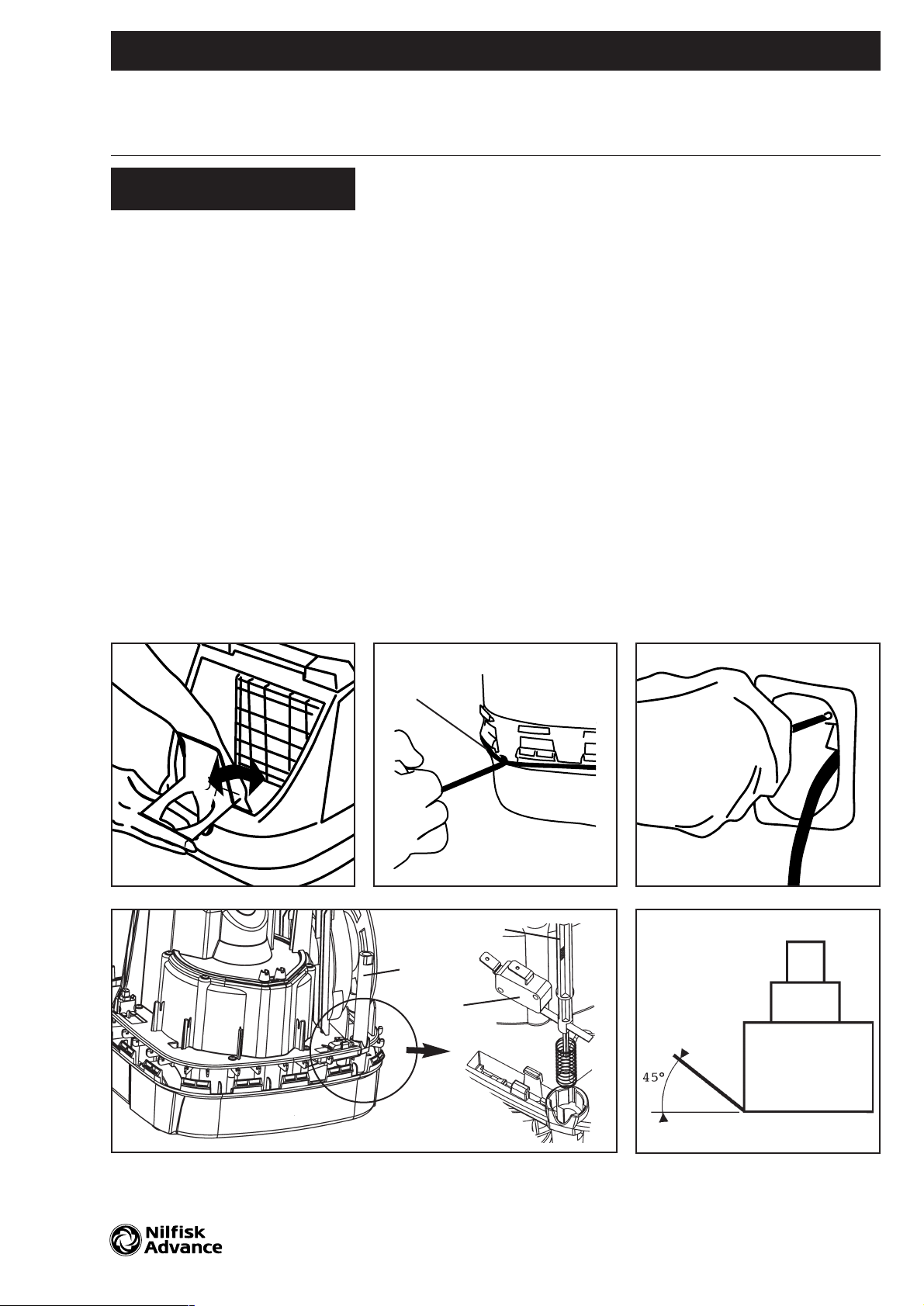
4) Remove and replace the
On/Off parking switch.
To release the switch, hold the
activator pin (5) with one hand and
release the switch (6) from the two
hooks and pull it away. Leave pin
(5) in its position.
Remove and replace the cords
to the switch (6).
Replace pin (5) by pushing it
downward to give the switch (6)
lever access to the hole in the
pin (5) and mount the switch (6).
Remove the cord reel and lock
the cord to the reel. Remove
internal wires and release the
on/off switch by pressing a
screwdriver under it.
Remove and replace the new
two-speed PCB and/or the
on/off switch and connect
wires.
5) NOTE:
GM200/300/400 SERIES ONLY.
Bend the terminal pins about 45
degrees
Refit in reverse order. Press the
buffer back in place by hand
after mounting the strap around
the housings.
R
5
5
6
WE
T
Q
12
Page 10
31965001. Replacement with the two speed PCB for 1200W motor. A-0.6.5.
22365700. Replacement of the on/off switch 10
22354400. Replacement of the on/off switch for parking
ASSEMBLY INSTRUCTIONS GM 200 / 300 / 400 & KING 500 SERIES
Instruction No. 82185900/00-11
659643
Top view GM 200/300/400 Series
Capacitor
with foam
New cord
reel shown
Flex
Existing
motor housing
On/off switch
Two speed switch
Note 1
Top view
Note 1:
Internal blue wire to be turned up
and locked by a strap. (Only two
speed version).
Note 2:
ONLY GM200/300/400 SERIES
O-ring to be mounted only when
existing motor housing is for two
speed regulation with four grooves.
C1
R1
T1
D2
D1
R2
C2
Diagram for
one speed models
Diagram for
two speed models
NL
= RFI capacitor
= Thermo switch
= Resistor
Top view King 500 Series
One Speed
Two Speed
Capacitor
with foam
New cord
reel shown
659643
659643
On/off
Insulated terminal
Capacitor
with foam
New cord
reel shown
On/off
Insulated
terminal
On/off parking
Wrapping around post
Note 5
Page 11

22201100. Replacement of the thermostatic switch for the new 1200W motor A-0.6.5.
22231100. Replacement of the motor grommets (7) and frame (5) 11
ASSEMBLY INSTRUCTIONS GM 200 / 300 / 400 SERIES
Instruction No. 82201300/00-08
To be performed by a skilled
or instructed person only !
Disconnect the vacuum cleaner
from the power supply before
starting the work!
! Models with bag-full indicator:
Open the dust cover until it stops
and continue with a little pressure
by hand until it slides free of the
hinges.
Models with no bag-full indicator:
Open the dust cover and lift it out
of the hinges.
Remove filter with dust bag.
Remove the dust bag holder by
pressing bottom clip and ease the
holder out of the bottom. This
releases the hook at the container
wall.
@ To separate the top and bottom
housing and avoid scratches on the
parts, place tool no. V-33580 under
the buffer.
Follow instruction 82361500
Remove the strap by hand or tool
no. V 33581. Lift up the buffer and
remove the top housing.
# Free the cord with plug from the
terminal box in the top housing by
using a Pozi screwdriver no. 2 or in
old models press. it out by hand.
Remove the cord reel and lock the
cord to the reel. Remove internal
wires and release the on/off switch
by pressing a screwdriver under it.
Remove the motor housing with
four screws by a Pozi screwdriver
no. 2.
$ Remove the sound suppressor
(1) if provided and the cover (2) on
the motor housing with four screws
(3) and lift out the motor unit (4).
Unplug the existing internal wire kit
with thermostatic switch mounted
in the motor frame (5). Remove the
old and replace with the new thermostatic switch and press in place
into the slots (6) and press the
wires back in the slots on top of the
motor frame (5). Refit in reverse
order.
Press the buffer back in place by
hand after mounting the strap
around the housings.
Q
WE
Q
1
2
7
5
6
4
3
R
Page 12

659643
View with existing motor housing removed.
Flex
Existing
motor housing
Note 1:
Internal blue wire to be turned up
and locked by a strap. (Only two
speed version).
Note 2:
O-ring to be mounted only when
existing motor housing is for two
speed regulation with four
grooves.
On/off switch
22201100. Replacement of the thermostatic switch for the new 1200W motor A-0.6.5.
22231100. Replacement of the motor grommets (7) and frame (5) 12
ASSEMBLY INSTRUCTIONS GM 200 / 300 / 400 SERIES
Instruction No. 82201300/00-08
Note 2
Top view
New cord
reel shown
Capacitor
with foam
Two speed switch
Diagram for
GM 200E/200/300/310/310S
218408xx
NL
81842200
81842200
31965001
C1
R1
T1
D2
D1
R2
C2
218408 xx
Diagram for GM 420/425/430
with two speed regulation
PCB for 1200W motor
and parking on/off
switch
(81842201)
31965001
C1
R1
T1
D2
D1
R2
C2
(118408 xx)
On/off
Parking
Two speed
Diagram for GM 210/320/325/330 with two speed
regulation PCB for 1200W motor
Armature Field coil Cord reel
On/off switch Resistor Capacitor
Thermo switch
Symbol explanation
Note 1
Note 2
Page 13

22226000. Replacement of the buttons for dust cover (1), cable reel (3) and on/off (4)
A-0.6.5
22226300. Replacement of the buttons for two speed regulation (6) and on/off (8)
13
218580xx. Replacement of the top housing (12)
223535xx. Replacement of the top housing King
22352900. Replacement of the On/Off button (4)
22352901. Replacement of the On/Off button two speed (8) with activator (7)
22353100. Replacement of the activator for cord reel
22353200. Replacement of the activator for On/Off
22353900. Replacement of the buttons for dust lid (1), cable reel (3) with pivots (2)
ASSEMBLY INSTRUCTIONS GM 200 / 300 / 400 & KING 500 SERIES
Instruction No. 82226401/00-08
To be performed by a skilled
or instructed person only !
Disconnect the vacuum cleaner
from the power supply before
starting the work!
Removal of the dust cover
button (1), cable reel button (3)
and on/off button (4) for one
speed models
Open the accessory cover until it
stops and continue with a little
pressure by hand until it slides free
of the hinges and remove it.
Open the dust cover lid.
! Push down the cable release
button (a) and press by hand the
dust cover button sideways (b) to
release it, and lift it up (c).
@ Release and remove the side
pivots (2) with a pair of pliers (5). To
remove the cable reel (3) and/or
the on/off button (4), press the two
snaps on the button to release it
from the top housing & lift it away
after turning it 30 degrees.
# How to disassemble
the machine
Open the accessory cover until it
stops and continue with a little
pressure by hand until it slides free
of the hinges and remove it.
Models with bag-full indicator:
Open the dust cover (9) until it
stops and continue with a little
pressure by hand until it slides free
of the hinges.
Models with no bag-full indicator:
Open the dust cover (9) and lift it
out of the hinges.
Remove filter with dust bag.
Remove the dust bag holder (10)
by pressing bottom clip and ease
the holder out of the bottom. This
releases the hook at the container
wall.
To separate the top and bottom
housing and avoid scratches on
the parts, place tool no. 22361400
(11) under the buffer.
3
1
4
5
2
9
10
2
E
12
a
b
c
Q
W
Page 14

Instruction No. 82226401/00-08
22226000. Replacement of the buttons for dust cover (1), cable reel (3) and on/off (4)
A-0.6.5
22226300. Replacement of the buttons for two speed regulation (6) and on/off (8)
14
218580xx. Replacement of the top housing (12)
223535xx. Replacement of the top housing King
22352900. Replacement of the On/Off button (4)
22352901. Replacement of the On/Off button two speed (8) with activator (7)
22353100. Replacement of the activator for cord reel
22353200. Replacement of the activator for On/Off
22353900. Replacement of the buttons for dust lid (1), cable reel (3) with pivots (2)
ASSEMBLY INSTRUCTIONS GM 200 / 300 / 400 & KING 500 SERIES
Tool to be used for: Tool type
Two speed regulation button (6) Sloth screwdriver 3,5mm
Side pivot (2) Pair of pliers (5)
$ Removal of the two speed
regulation button (6) and/or
the on/off button (8) for two
speed regulation models,
and/or the activators.
Press a screwdriver into the inside
bush (7) of the two speed regulation button, turn it clock-wise 90
degree and pull it away. Remove
the button (6) with the spiral spring.
Removal of the on/off button (8):
Remove the two-speed regulation
button (6) as described.
Press the two snaps on the
button (8) to release it from the
top housing and lift it away after
turning it 30 degrees.
Removal of the on/off activator:
Snap off, break, activator for on/off
button (23, 24, 25, 26).
Replace with new parts.
Replacement of the top housing
Remove dustcover buttom, cabel
reel button and on/off button.
Remove cabel terminal and screw,
retainer, ratches and handle accessory lid, see instruction 82362400.
Remove activator for cord reel (20,
21, 22). Remount buttons, cabel
terminal, retainer, accessory lid and
activator for cord reel, etc. on new
upper part.
Reassembly machine
Press the buffer in place by hand
after mounting the strap (12)
around the housings.
Replace in reverse order.
All models: Test after repair
After repair, please check that the
vacuum cleaner is functioning to
Nilfisk specifications and any local
authorised precautions.
3
1
6
20
21
22
8
2
7
R
24
23
26
25
Page 15

22361200. Replacing the pair of ratchet for dust cover A-0.6.5
15
ASSEMBLY INSTRUCTIONS GM 400 SERIES
Instruction No. 82361300/00-08
To be performed by a skilled
or instructed person only !
Converting from black ratchet to
the dark grey version
Q Open the accessory cover
until it stops and continue with a
little pressure by hand until it slides
free of the hinges and remove it.
Open the dust cover lid.
W Push down the cable release
button (a) and press by hand the
dust cover button sideways (b) to
release it, and lift it up (c).
E Unscrew the two screws with
a screwdriver type Pozidrive no.2
and remove with the steel plate.
RTRemove the two ratchets from
the spring and replace the two
dark grey versions into the spring.
Y When replacing the steel plate
be sure that the hooks on the
ratchets in both sides are in mesh
with hole in the steel plate.
Press down the steel plate and
replace the two screws with adequate force.
To replace the dust cover button,
push down the cable release button and press it by hand sideways
to fit the two tabs.
Replace the accessory cover and
lock the dust cover.
a
1
2
b
c
YT
Q
E
W
R
Page 16

A-0.6.5
16
Page 17

22352800. Replacement of the rear wheels A-0.6.5.
17
ASSEMBLY INSTRUCTIONS KING 500 SERIES
Instruction No. 82362100/00-08
To be performed by a skilled
or instructed person only !
Disconnect the vacuum cleaner
from the power supply before
starting the work!
! Models with bag-full indicator:
Open the dust cover until it stops
and continue with a little pressure
by hand until it slides free of the
hinges.
Models with no bag-full indicator:
Open the dust cover and lift it out
of the hinges.
Remove filter with dust bag.
Remove the dust bag holder by
pressing bottom clip and ease the
holder out of the bottom. This
releases the hook at the container
wall.
@ To separate the top and bottom
housing and avoid scratches on the
parts, place tool no. 22361400
under the buffer.
Follow instruction 82361500.
Remove the strap by hand or tool
no. V 33581. Lift up the buffer and
remove the top housing.
# Free the cord with plug from the
terminal box in the top housing by
using a Pozi screwdriver no. 2. Lift
away the upper housing.
Remove the cord reel and lock the
cord to the reel.
Unscrew from top the screw for the
wheel with a Torx T 20 screwdriver
and remove the shaft with wheel
from the bottom side.
Mount the new wheel with shaft by
the use of a small screwdriver and
a Torx T 20 screwdriver.
Mount shaft into wheel and
place a small screwdriver
through the hole for the metric
screw. Push wheel with shaft
and a small screwdriver into the
groove for wheel from the bottom side with small screwdriver
pointing through the metric hole.
When screw is positioned from
the upper side, the screw will
push out the small bottom
screwdriver.
Replace cords reel and lift the
upper housing back on top of
the bottom housing. Press the
buffer in place by hand after
mounting the strap around the
housings.
Replace the accessory cover
and lock the dust cover.
WE
Q
12
Page 18

One Speed
Two Speed
Capacitor
with foam
New cord
reel shown
22352800. Replacement of the rear wheels A-0.6.5.
18
ASSEMBLY INSTRUCTIONS KING 500 SERIES
Instruction No. 82362100/00-08
C1
R1
T1
D2
D1
R2
C2
Diagram for
one speed models
Diagram for
two speed models
NL
= RFI capacitor
= Thermo switch
= Resistor
659643
659643
On/off
Insulated terminal
Capacitor
with foam
New cord
reel shown
On/off
Insulated
terminal
On/off parking
Wrapping around post
Page 19

22353000. Replacing the dust lid retainer parts & black handle A-0.6.5
22353300. Replacing the accessory lid 19
22353400. Replacing the cable terminal and screw
22353600. Replacing the dust cover with indicator
22353700. Replacing the dust cover without indicator
22354500. Replacing the front filter frame
ASSEMBLY INSTRUCTIONS GM 200 / 300 / 400 & KING 500 SERIES
Instruction No. 82362400/00-08
To be performed by a skilled
or instructed person only !
Disconnect the vacuum cleaner
from the power supply before
starting the work!
Replacement of the dust cover,
22353600, 22353700:
With indicator- Open the dust cover until it stops and continue with a
little pressure by hand until it slides
free of the hinges.
Without indicator- Open the dust
cover until it slides free of the
hinges.
Replace in reverse order.
Replacement of the front filter
frame, 22354500:
Open the dust cover and remove
the dust bag and front filter.
Remove the frame by lifting it away
from the four brackets. When
replacing it must snap back in four
places.
Replace in reverse order.
Replacement of the cable
terminal and screw, 22353400:
Pull out the plug and unscrew the
screw with a Pozi drive screwdriver
no.2 and remove the cable terminal
by guiding the cord through the
slot in it.
Replace in reverse order.
Replacement of the accessory
lid, 22353300:
Open the accessories lid to vertical
position and pull it away.
Release the hinge tube snap with a
screwdriver and slide out the part.
Replace the new hinge tube by
sliding it back until it clicks into
position.
Replace in reverse order.
Replacement of the dust lid
retainer parts & black handle,
22353000:
Q Open the accessory lid until it
stops and continue with a little
pressure by hand until it slides free
of the hinges and remove it. Open
the dust cover.
W Push down the cable release
button (a) and press by hand the
dust cover button sideways (b) and
up (c) to release it.
E Unscrew the two screws with a
screwdriver type Pozidrive no.2
and remove with the steel plate.
Now the black handle can be
replaced.
RT Remove the two ratchets
from the spring and replace the
two dark grey versions into the
spring.
Remove and replace the black
handle
Y When replacing the steel plate
be sure that the hooks on the
ratchets in both sides are in mesh
with hole in the steel plate.
Press down the steel plate and
replace the two screws with adequate force.
To replace the dust cover button,
push down the cable release button and press it by hand sideways
to fit the two tabs.
Replace the accessory lid and lock
the dust cover.
a
1
2
b
c
YT
Q EW
R
U
Page 20

A-0.6.5
20
Page 21

22358500. Replacing the active carbon filter A-0.6.5
21
ASSEMBLY INSTRUCTIONS KING 500 SERIES
Instruction No. 82358700/00-08
1
Page 22

A-0.6.5
22
Page 23

22353800. Replacing the front hinge for dust cover A-0.6.5
22354200. Replacing the Bottom part 23
22354300. Replacing the Gaskets for suction house
ASSEMBLY INSTRUCTIONS KING 500 SERIES
Instruction No. 82362200/00-08
To be performed by a skilled
or instructed person only !
Disconnect the vacuum cleaner
from the power supply before
starting the work!
! Models with bag-full indicator:
Open the dust cover until it stops
and continue with a little pressure
by hand until it slides free of the
hinges. Models with no bag-full
indicator: Open the dust cover and
lift it out of the hinges.
Remove filter with dust bag.
Remove the dust bag holder by
pressing bottom clip and ease the
holder out of the bottom. This
releases the hook at the container
wall.
@ To separate the top and bottom
housing and avoid scratches on the
parts, place tool no. 22361400
under the buffer.
Follow instruction 82361500
Remove the strap (12) by hand or
tool no. V 33581. Lift up the buffer
and remove the top housing.
Removal and replace of the front
hinge, 22353800
Disassemble the machine.
Lift-up the buffer(13) by hand.
Remove the hinge with a flat-headed screwdriver by pressing at the
snap lock and pull away the hinge.
Refit in reverse order.
$ Removal and replace of the
bottom part, 22354200
Disassemble the machine.
Lift-up the buffer(13) and remove
the strap(12) by hand and lift away
the bottom part.
Loosen the four screws (16) for the
HEPA filter in the bottom housing
by turning them through 90
degrees using a coin (17). Pull out
the tube (18) with your finger tips.
Unscrew the five screws (10) in
the bottom to release it from the
suction house. Remove the cord
reel.
Unscrew from top the two screws
(11) for the wheel with a Torx T 20
screwdriver and remove the shaft
with wheel from the bottom side.
Mount the wheel into the new bottom with shaft by the use of a
small screwdriver and a Torx T 20
screwdriver.
Mount shaft into wheel and place a
small screwdriver through the hole
for the metric screw. Push wheel
with shaft and a small screwdriver
into the groove for wheel from the
bottom side with small screwdriver
pointing through the metric hole.
When screw is positioned from the
upper side, the screw will push out
the small bottom screwdriver.
Remove the two front hinges.
Refit in reverse order.
Removal and replace of the
Gaskets for suction house,
22354300
Disassemble the machine.
Lift-up the buffer (13) and remove
the strap (12) by hand and lift away
the bottom part. Loosen the four
screws (16) for the HEPA filter in
the bottom housing by turning
them through 90 degrees using a
coin (17). Pull out the tube (18) with
your finger tips.
Unscrew the five screws(10) in the
bottom to release it from the suction house and replace the two
gaskets(14-15). Refit in reverse
order.
Assembling of the machine.
Position the upper part on the bottom part, replace the strap(12)
between the hooks and press by
hand the buffer(13) until it snaps
the two parts together
WE
Q
12
Page 24

22353800. Replacing the front hinge for dust cover A-0.6.5
22354200. Replacing the Bottom part 24
22354300. Replacing the Gaskets for suction house
ASSEMBLY INSTRUCTIONS KING 500 SERIES
Instruction No. 82362200/00-08
14
15
11
10
17
16
18
Page 25

22352200. Replacing the Motor/Fan unit A-0.6.5
22352400. Replacing the internal wires for one speed motor 25
22352500. Replacing the internal wires for two speed motor
22352700. Replacing the Motor suspension
22354000. Replacing the Motor tube
22354100. Replacing the suction house
ASSEMBLY INSTRUCTIONS KING 500 SERIES
Instruction No. 82362500/00-08
To be performed by a skilled
or instructed person only !
Disconnect the vacuum cleaner
from the power supply before
starting the work!
Follow instruction 82362200 first
1,2,3
How to disassemble the
machine.
Loosen the four screws (16) for the
HEPA filter in the bottom housing
by turning them through 90
degrees using a coin (17). Pull out
the tube (18) with your fingertips.
To separate the top and buttom
housing and avoid scratches on
the parts, place tool no. 22361400
under the buffer.
Follow instruction 82361500
Remove the strap by hand and lift
away the top housing.
Replacing the motor/fan unit
22352200.
Replacing the motor suspension
22352700.
Replacing the motor tube
22354000.
Disassemble the machine.
Remove the wires from the two terminal spades (23) and press down
to free them from the rubber gaskets, unscrew the six screws (22)
from top and pull out the motor
tube (20) with the two red internal
wires.
Remove and replace the motor/fan
(25) unit with rubber suspension
(27-28-29-30) and/or internal red
wires.
When replacing the internal wires
wrap them around the two small
fixtures (32) on the motor suspension (28). When replacing with new
motor suspension parts, press by
hand to click item 27 & 28 together
(29), before mounting onto the
motor/fan unit.
Before replacing the motor tube
(20), place the two-rubber gaskets
(26) with the slots in opposite position and with the terminal spades
(23) pulled back into the rubber
gaskets (26).
Replace the motor/fan unit (25)
with the bow tie formed motor suspension (29) turned to fit to the
same form (31) in the bottom of the
tube (20). Mount the motor tube
(20) unit with internal red wires to
the suction house (19) with the six
screws (22).
Replace the internal wires
according to wiring diagram.
Refit in reverse order.
Removal and replacement of the
suction house (19), 22354100
Disassemble the machine.
Unscrew from top the screw (11)
for the wheel with a Torx T 20
screwdriver and remove the shaft
with wheel from the bottom side.
Unscrew the five screws (10) in the
bottom to release it from the suction house (19) and replace the
gasket (15) on the new suction
house(19).
Unscrew the six screws (22) from
top and pull out the motor tube
(20) with the two internal wires. Be
sure to remember the upper motor
suspension (30).
Remove and replace the On/Off
parking switch.
To release the switch, hold the
activator pin (7) with one hand and
release the switch (8) from the two
hooks and pull it away. Remove
and replace the pin (7) with spring
into the bush of the housing.
Remove and replace the cords to
the switch (8).
Replace pin (7) by pushing it
downward to give the switch (8)
lever access to the hole in the pin
(7) and mount the switch (8).
Remove and replace the On/Off
switch, Two speed PCB and internal wires (5-6).
Mount the wheel with shaft by the
use of a small screwdriver and a
Torx T 20 screwdriver.
Mount shaft into wheel and place a
small screwdriver through the hole
for the metric screw. Push wheel
with shaft and a small screwdriver
into the groove for wheel from the
bottom side with small screwdriver
pointing through the metric hole.
When screw (11) is positioned from
the upper side, the screw (11) will
push out the small bottom screwdriver.
Refit in reverse order.
Assembling of the machine
Position the upper part on the bottom part, replace the strap (12)
between the hooks and press by
hand the buffer (13) until it snaps
the two parts together.
Page 26

22352200. Replacing the Motor/Fan unit A-0.6.5
22352400. Replacing the internal wires for one speed motor 26
22352500. Replacing the internal wires for two speed motor
22352700. Replacing the Motor suspension
22354000. Replacing the Motor tube
22354100. Replacing the suction house
ASSEMBLY INSTRUCTIONS KING 500 SERIES
Instruction No. 82362500/00-08
T
op view King 500 Series internal wires
One Speed
Two Speed PCB
Capacitor
with foam
New cord
reel shown
659643
659643
On/off
Insulated terminal
Capacitor
with foam
New cord
reel shown
On/off
Insulated
terminal
On/off parking
Wrapping around post
C1
R1
T1
D2
D1
R2
C2
Diagram for
one speed models
Diagram for
two speed models
NL
= RFI capacitor
= Thermo switch
= Resistor
30
8
7
15
24
25
28
27
29
29
32
25
20
23
20
26
31
8
19
22
22
10
11
23
Page 27

22361400. Disassembly tool of top and bottom housing A-0.6.5.
27
ASSEMBLY INSTRUCTIONS GM 200 / 300 / 400 & KING 500 SERIES
To be performed by a skilled
or instructed person only !
Instruction No. 82361500/00-08
Disconnect the vacuum cleaner
from the power supply before
starting the work!
1. Remove the lid, dust bag,
guide and guideway.
4. Grip the handle firmly. Gently
press the front of the vacuum
cleaner while simultaneously
lifting the handle. Push down
to the position shown.
Dust bag
Guide and guideway
Filter and filtergrid
2. Remove filter and filtergrid.
Disassembly tool
3. Place the vacuum cleaner on
the top of the disassembly
tool.
Lid for accessories
Page 28

5. The back af the vacuum cleaner must rest on the internal
edge of the disassembly tool.
6. Press down the front of the
vacuum cleaner as shown.
7. Remove the lid for
accessories. Press down the
back of the vacuum cleaner.
Now you can lift off the buffer.
8. Refit in reverse order.
Press the buffer back in place
by hand after mounting the
strap around the housing.
22361400. Disassembly tool of top and bottom housing A-0.6.5.
28
ASSEMBLY INSTRUCTIONS GM 200 / 300 / 400 & KING 500 SERIES
Instruction No. 82361500/00-08
Page 29

22389400. Inner parts for dustlid with indicator GMxxx & KING A-0.6.5.
22301700. Dust lid black for models with dust indicator 29
22389300. Inlet for dustlid with dust indicator GMxxx & KING
ASSEMBLY INSTRUCTIONS GM 200 / 300 / 400 & KING 500 SERIES
To be performed by a skilled
or instructed person only !
Instruction No. 82389100/01-11
Remove the old dust cover.
Open the dust cover until it
stops and continue with a
little pressure by hand until it
slides free of the hinges.
Assembly new dust cover.
(1) Apply water or acidfree
oil around the inlet on the
outer lid.
(2) Press the inner lid into
outer lid. Let the two snaps
click into place.
Screw in the two screws.
Replaced dust cover in
reverse order.
(2)
(1)
Page 30

A-0.6.5.
30
ASSEMBLY INSTRUCTIONS GM 200 / 300 / 400 & KING 500 SERIES
Instruction No.
Page 31

22410600 A-0.6.5.
31
ASSEMBLY INSTRUCTION - ADAPTOR FOR DUST COVER - GM 200/GM 210 - ONLY
Instruction No. 82410700/01-11
Page 32

A-0.6.5.
32
Instruction No.
 Loading...